38
MAE 6530 - Propulsion Systems II Section 6.1: The TurboFan Propulsion Cycle 1
MAE 6530 - Propulsion Systems II
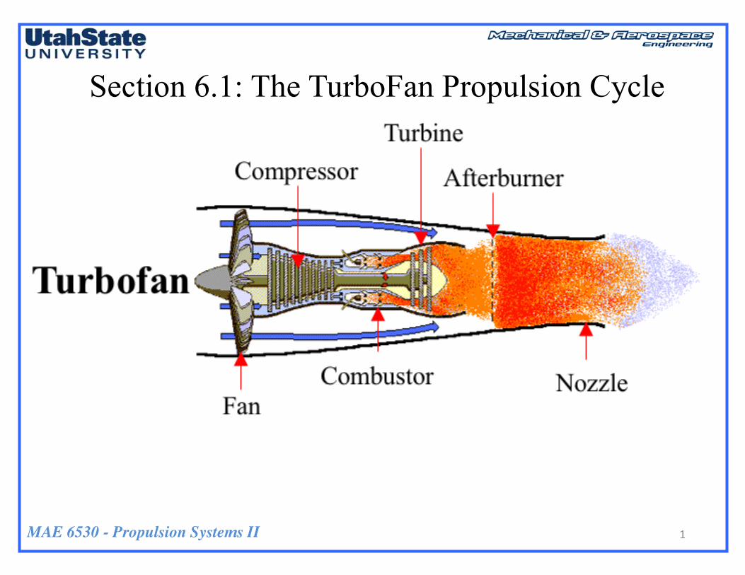
Section 6.1: The TurboFan Propulsion Cycle
1

MAE 6530 - Propulsion Systems II
Overview
2

MAE 6530 - Propulsion Systems II
Overview (2)
3
• Turbofan engine is the most modern variation of the basic gas turbine engine. • As with other gas turbines, there is a core engine, whose parts and operation are nearly identical to the turbojet operation. • In the turbofan engine, the core engine is surrounded by a fan in the front and an additional turbine at the rear.
MAE 6530 - Propulsion Systems II
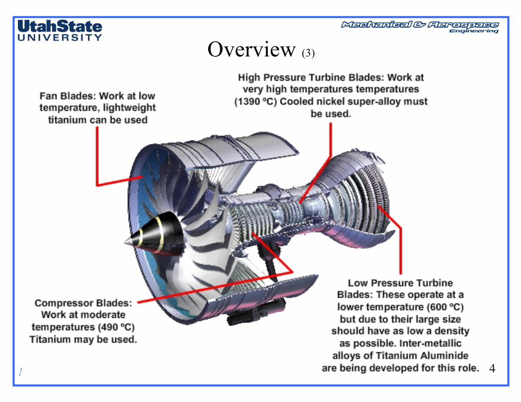
Overview (3)
4

MAE 6530 - Propulsion Systems II
Overview(4)
5
• Turbofan engines power now all civil transports flying at transonic speeds up to Mach 0.9. • Several advantages to turbofan engines over both propeller-driven and turbojet engines• By enclosing fan inside a duct or cowling, aerodynamics are better controlled. • Fan is not as large as propeller, so increase of speeds along blade is less, and there is less chance of tip stall and shock wave development.• Turbofan can suck in more total air massflow than a turbojet, thus offer potential for generating more thrust. • Turbofan has low fuel consumption compared with turbojet.

MAE 6530 - Propulsion Systems II
Jet Engine Performance Efficiency (revisited)
6
Kinetic energy production rate
Propulsive power
Propulsive EfficiencyRatio of Power Developed from Engine (desired beneficial output) Thrust to Change in Kinetic Energy of the Moving Airstream (cost of propulsion)
Maximum propulsive efficiency achieved by generating thrust moving as much air as possible with as little a change in velocity across the engine as possible.

MAE 6530 - Propulsion Systems II
Jet Engine Performance Efficiency (2)
7
• Maximum propulsive efficiency achieved by generating thrust moving as much air as possible with as little a change in velocity across the engine as possible. .. Fan provides that function

MAE 6530 - Propulsion Systems II
Jet Engine Performance Efficiency (3)
8
• Recall that optimal thrust level of a turbo jet is characterized by
τc( )opt =1τr⋅ 1+ 1
f
⎛
⎝⎜⎜⎜
⎞
⎠⎟⎟⎟⎟τλ Πc( )
opt= τc
γγ−1
⎛
⎝
⎜⎜⎜⎜⎜
⎞
⎠
⎟⎟⎟⎟⎟opt
=
• As supersonic flight Mach become larger, compression goes down until
…. optimal solution gets rid of compressor all together, and best engine becomes a ramjet!
1= 1τr⋅ 1+ 1
f⎛
⎝⎜⎜⎜
⎞
⎠⎟⎟⎟⎟τλ → τλ =
ff +1
τr2

MAE 6530 - Propulsion Systems II
Jet Engine Performance Efficiency (4)
9
• We are going to show that similar effect occurs as Mach drops significantly below Mach 1
• Trend emerges that replaces turbojet with Turbofan at lower Mach numbers
Decreasing Mach Number

MAE 6530 - Propulsion Systems II
Classification of Turbofan Engines
10

MAE 6530 - Propulsion Systems II
Classification of Turbofan Engines (2)
11
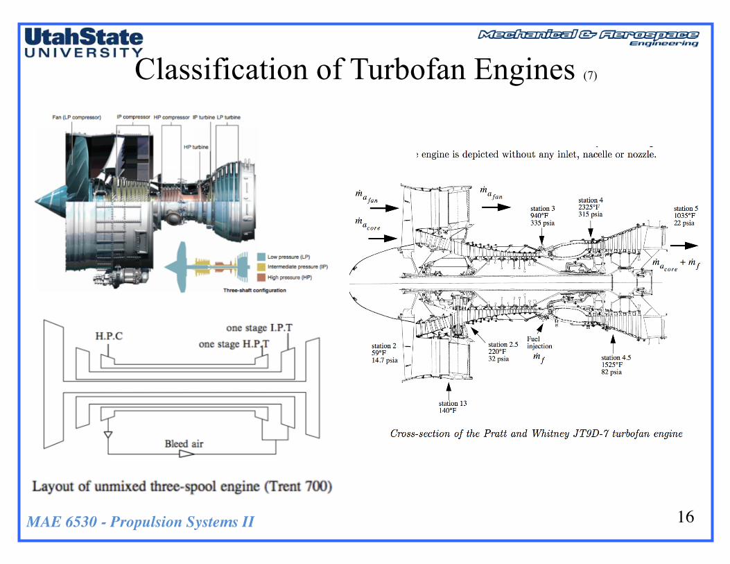
• Turbofan engines may be classified based on fan location as either forward or aft fan. • Based on a number of spools, engine may be classified as single, double, or triple spools. •Based on a bypass ratio, engine may be categorized as either low-or high- bypass ratio. • Fan may be geared or ungeared to its driving low-pressure turbine. • Mixed-flow types (where flow merges in nozzle) may be fitted with afterburner.

MAE 6530 - Propulsion Systems II
Classification of Turbofan Engines (3)
12
• High-bypass ratio turbofan (β > 5) achieves 75 % of thrust from bypass air
- Ideal for subsonic transport aircraft. e.g. - Rolls-Royce Trent series (Airbus A330, A340, A350, A380), - Pratt & Whitney PW1000 G (geared) (Airbus A320neo, Bombardier
CSeries, Embraer E2, Mitsubishi Regional Jet MC-21) - General Electric GE90 powering Boeing 777-300ER, 747.
• Low-bypass ratio turbofan β ~ 1 achieves approximately equal thrust distribution between gas generator and bypass duct
- Well suited to high-speed military applications. e.g. - Rolls-Royce RB199 in the Tornado- Pratt & Whitney F100-PW-200 in F-16A/B and F-15- EuroJet Turbo GmbH EJ200 powering the Typhoon Fighter

MAE 6530 - Propulsion Systems II
Classification of Turbofan Engines (4)
13
• Unmixed Bypass Flow Turbofan
• Mixed Bypass Flow Turbofan
2-spool, low-bypass turbofanengine with a mixed exhaust,showing the low-pressure(green) and high-pressure(purple) spools.
2-Spool High-bypass turbofanengine with a unmixedexhaust, showing the fan(pink) and core (red) exhauststreams

MAE 6530 - Propulsion Systems II
Classification of Turbofan Engines (5)
14
• Modern high bypass ratio engine designed for long distance cruise at subsonicMach numbers around 0.83.• Fan uses a single stage composed of a large diameter fan (rotor) with wide chordblades followed by a single nozzle stage (stator).• Bypass ratio is ~6 and the fan pressure ratio is ~2.
High Bypass Ratio

MAE 6530 - Propulsion Systems II
Classification of Turbofan Engines (6)
15
• Military turbofan designed for high performance at supersonic Mach numbers in the range of 1.1 to 1.5. • Fan has three stages with an overall pressure ratio of about 6 and a bypass ratio of only about 0.6. • Let’s investigate to understand why these engines look so different due to the the differences in the design flight condition.
Low Bypass Ratio
MAE 6530 - Propulsion Systems II
Classification of Turbofan Engines (7)
16
MAE 6530 - Propulsion Systems II
Thrust of a TurboFan Engine
17
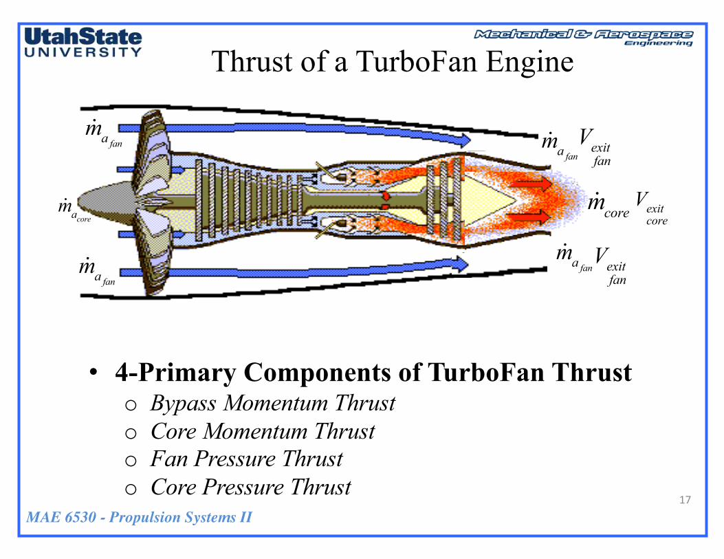
• 4-Primary Components of TurboFan Thrusto Bypass Momentum Thrusto Core Momentum Thrusto Fan Pressure Thrust o Core Pressure Thrust
!macore
!mafan
!mafan
Vexitcore
Vexitfan
Vexitfan
!mafan
!mafan
!mcore

MAE 6530 - Propulsion Systems II
Thrust of a TurboFan Engine (2)
18
Fthrust = !macore ⋅ Vexitcore−V∞
⎛
⎝⎜⎜⎜⎜
⎞
⎠⎟⎟⎟⎟+ !mfuel ⋅Vexit
core+ !mafan ⋅ Vexit
fan−V∞
⎛
⎝⎜⎜⎜⎜
⎞
⎠⎟⎟⎟⎟+ pexit
core− p∞
⎛
⎝⎜⎜⎜⎜
⎞
⎠⎟⎟⎟⎟⋅ Aexit
core+ pexit
fan− p∞
⎛
⎝⎜⎜⎜⎜
⎞
⎠⎟⎟⎟⎟⋅ Aexit
fan
Core Momentum Bypass Momentum Core Pressure Bypass Pressure Thrust Thrust Thrust Thrust
!macore
!mafan
!mafan
Vexitcore
Vexitfan
Vexitfan
!mafan
!mafan
!mcore

MAE 6530 - Propulsion Systems II
Thrust of a TurboFan Engine (3)
19
Total Air Massflow!ma = !macore + !mafan
→
Air− to− fuel Ratio
f =!ma!mfuel
Bypass Ratio
β=!mafan!macore=
B1−B
Bypass Fraction
B=!mafan!ma=β
1+β
Fthrust = !ma!macore!ma⋅ Vexit
core−V∞
⎛
⎝⎜⎜⎜⎜
⎞
⎠⎟⎟⎟⎟+!mfuel
!ma⋅Vexitcore+!mafan!ma⋅ Vexit
fan−V∞
⎛
⎝⎜⎜⎜⎜
⎞
⎠⎟⎟⎟⎟
⎡
⎣
⎢⎢⎢
⎤
⎦
⎥⎥⎥+ pexit− p∞( )⋅ Aexit + p1exit− p∞( )⋅ Aexit
fan
!macore!ma=
!macore!macore + !mafan
=1
1+!mafan!macore
=1
1+β
!macore!ma=!ma− !mafan!ma
=1−B
!mafan!ma= B= β
1+β, !mfuel
!ma=
1f
→
Fthrust = !ma1
1+β⋅ Vexit
core−V∞
⎛
⎝⎜⎜⎜⎜
⎞
⎠⎟⎟⎟⎟+
1f⋅Vexitcore+β
1+β⋅ Vexit
fan−V∞
⎛
⎝⎜⎜⎜⎜
⎞
⎠⎟⎟⎟⎟
⎡
⎣⎢⎢
⎤
⎦⎥⎥+
pexitcore− p∞
⎛
⎝⎜⎜⎜⎜
⎞
⎠⎟⎟⎟⎟⋅ Aexit
core+ pexit
fan− p∞
⎛
⎝⎜⎜⎜⎜
⎞
⎠⎟⎟⎟⎟⋅ Aexit
fan
MAE 6530 - Propulsion Systems II
Thrust of a TurboFan Engine (4)
20
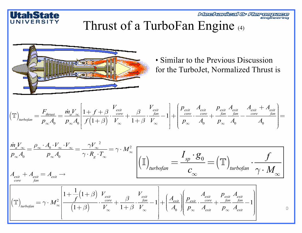
• Similar to the Previous Discussion for the TurboJet, Normalized Thrust is
T( )turbofan
=Fthrustp∞A0
=!maV∞p∞A0
1+ f +βf 1+β( )
⋅Vexitcore
V∞+β1+β
⋅Vexitfan
V∞−1
⎡
⎣
⎢⎢⎢⎢
⎤
⎦
⎥⎥⎥⎥+pexitcore
p∞⋅Aexitcore
A0+pexitfan
p∞
Aexitfan
A0−Aexitcore+ Aexit
fan
A0
⎛
⎝
⎜⎜⎜⎜⎜⎜⎜
⎞
⎠
⎟⎟⎟⎟⎟⎟⎟⎟=
!maV∞p∞A0
=ρ∞ ⋅ A0 ⋅V∞ ⋅V∞
p∞A0=γV∞
2
γ ⋅Rg ⋅T∞= γ ⋅M∞
2
Aexitcore+ Aexit
fan= Aexit→
T( )turbofan
= γ ⋅M∞21+ 1
f1+β( )
1+β( )⋅Vexitcore
V∞+β1+β
⋅Vexitfan
V∞−1
⎡
⎣
⎢⎢⎢⎢⎢⎢
⎤
⎦
⎥⎥⎥⎥⎥⎥
+AexitA0
⎛
⎝⎜⎜⎜⎜
⎞
⎠⎟⎟⎟⎟⎟pexitp∞⋅Aexitcore
Aexit+pexitfan
p∞
Aexitfan
Aexit−1
⎛
⎝
⎜⎜⎜⎜⎜⎜⎜
⎞
⎠
⎟⎟⎟⎟⎟⎟⎟⎟
I( )turbofan
=Isp ⋅g0c∞
= T( )turbofan
⋅f
γ ⋅M∞

MAE 6530 - Propulsion Systems II
Thrust of a TurboFan Engine (5)
21
• Fully expanded nozzle & f >> 1 • Inlet, fan, compressor, turbine, and fan /core nozzles are isentropic• Combustor heat addition is as constant pressure and Low Mach
Toptimal( )turbofan
= γ ⋅M∞2 1
1+β⎛
⎝⎜⎜⎜
⎞
⎠⎟⎟⎟⎟⋅Vexitcore
V∞+
β1+β⎛
⎝⎜⎜⎜
⎞
⎠⎟⎟⎟⎟⋅Vexitfan
V∞−1
⎡
⎣
⎢⎢⎢⎢
⎤
⎦
⎥⎥⎥⎥=
= γ ⋅M∞2 1
1+β⎛
⎝⎜⎜⎜
⎞
⎠⎟⎟⎟⎟⋅Vexitcore
V∞−1
⎛
⎝
⎜⎜⎜⎜⎜⎜⎜
⎞
⎠
⎟⎟⎟⎟⎟⎟⎟⎟+
β1+β⎛
⎝⎜⎜⎜
⎞
⎠⎟⎟⎟⎟⋅Vexitfan
V∞−1
⎛
⎝
⎜⎜⎜⎜⎜⎜⎜
⎞
⎠
⎟⎟⎟⎟⎟⎟⎟⎟
⎡
⎣
⎢⎢⎢⎢⎢
⎤
⎦
⎥⎥⎥⎥⎥
pexitfan= pexit
core= p∞ → πd = πb = πncore = πn
fan=1
πccore= τc
core
⎛
⎝⎜⎜⎜⎜
⎞
⎠⎟⎟⎟⎟
γγ−1,πc
fan= τc
fan
⎛
⎝⎜⎜⎜⎜⎞
⎠⎟⎟⎟⎟
γγ−1,πt = τt( )
γγ−1 .
Ioptimal( )turbofan
= Toptimal( )turbofan
⋅f
γ ⋅M∞

MAE 6530 - Propulsion Systems II
The Ideal TurboFan Cycle
22
• Look at Fan Bypass Flow Stream
• Look at by pass velocity ratio
• First calculate bypass exit stagnation pressure
Vexitfan
V∞=Mexit
fan
M∞⋅Texitfan
T∞
→ P0exitfan
=P0∞
p∞⋅P01
P0∞
⋅P02
P01
⋅P0exit
fan
P02
⋅ p∞ → ideal cycle→ πd =P01
P0∞
⋅P02
P01
=1
→ P0exitfan
= πr ⋅πcfan⋅ p∞ = pexit
fan⋅ 1+ γ+1
2Mexit
fan
2⎛
⎝⎜⎜⎜⎜
⎞
⎠⎟⎟⎟⎟
γγ−1
!mafan Vexitfan
V∞
• Too lengthy to analyze all types of turbofan engines. So, only a simple single spool fan, compressor, turbine cycle will be analyzed

MAE 6530 - Propulsion Systems II
The Ideal TurboFan Cycle (2)
23
• Look at Fan Bypass Flow Stream
fully expanded nozzle → pexitfan= p∞
⎧⎨⎪⎪⎩⎪⎪
⎫⎬⎪⎪⎭⎪⎪→ πr ⋅πc
fan= 1+ γ+1
2Mexit
fan
2⎛
⎝⎜⎜⎜⎜
⎞
⎠⎟⎟⎟⎟
γγ−1
Isentropic fan→ πcfan= τc
fan
⎛
⎝⎜⎜⎜⎜⎞
⎠⎟⎟⎟⎟
γγ−1→ τr ⋅τc
fan= 1+ γ+1
2Mexit
fan
2⎛
⎝⎜⎜⎜⎜
⎞
⎠⎟⎟⎟⎟
τr =T0∞
T∞1+ γ+1
2M∞
2⎛
⎝⎜⎜⎜
⎞
⎠⎟⎟⎟⎟→γ+1
2M∞
2 = τr−1
→γ+12Mexit
fan
2 = τr ⋅τcfan−1→
γ+12Mexit
fan
2
γ+12M∞
2=τr ⋅τc
fan−1
τr−1→
Mexitfan
2
M∞2 =
τr ⋅τcfan−1
τr−1
!mafanVexitfan
V∞

MAE 6530 - Propulsion Systems II
The Ideal TurboFan Cycle (3)
24
• Look at Fan Bypass Flow Stream
Substitute
Vexitfan
V∞=Mexit
fan
M∞⋅Texitfan
T∞=
τr ⋅τcfan−1
τr−1
⎛
⎝
⎜⎜⎜⎜⎜⎜⎜
⎞
⎠
⎟⎟⎟⎟⎟⎟⎟⎟⋅Texitfan
T∞→ isentropic fan→ pexit
fan
⎛
⎝⎜⎜⎜⎜⎞
⎠⎟⎟⎟⎟
γ−1γ
= p∞( )γ−1γ
→Texitfan=T∞
Vexitfan
V∞
⎛
⎝
⎜⎜⎜⎜⎜⎜⎜
⎞
⎠
⎟⎟⎟⎟⎟⎟⎟⎟
2
=τr ⋅τc
fan−1
τr−1
⎛
⎝
⎜⎜⎜⎜⎜⎜⎜
⎞
⎠
⎟⎟⎟⎟⎟⎟⎟⎟→ T( )
fan= γ ⋅M∞
2 β1+β⎛
⎝⎜⎜⎜
⎞
⎠⎟⎟⎟⎟⋅Vexitfan
V∞−1
⎛
⎝
⎜⎜⎜⎜⎜⎜⎜
⎞
⎠
⎟⎟⎟⎟⎟⎟⎟⎟
⎡
⎣
⎢⎢⎢⎢⎢
⎤
⎦
⎥⎥⎥⎥⎥
= γ ⋅M∞2 β
1+β⎛
⎝⎜⎜⎜
⎞
⎠⎟⎟⎟⎟⋅τr ⋅τc
fan−1
τr−1−1
⎛
⎝
⎜⎜⎜⎜⎜⎜⎜⎜
⎞
⎠
⎟⎟⎟⎟⎟⎟⎟⎟⎟
⎡
⎣
⎢⎢⎢⎢⎢
⎤
⎦
⎥⎥⎥⎥⎥
Fan Thrust

MAE 6530 - Propulsion Systems II
The Ideal TurboFan Cycle (4)
25
• Look at Fan Bypass Flow Stream
• Fan Thrust
Substitute
Vexitfan
V∞=Mexit
fan
M∞⋅Texitfan
T∞=
τr ⋅τcfan−1
τr−1
⎛
⎝
⎜⎜⎜⎜⎜⎜⎜
⎞
⎠
⎟⎟⎟⎟⎟⎟⎟⎟⋅Texitfan
T∞→ isentropic fan→ pexit
fan
⎛
⎝⎜⎜⎜⎜⎞
⎠⎟⎟⎟⎟
γ−1γ
= p∞( )γ−1γ
→Texitfan=T∞
Vexitfan
V∞
⎛
⎝
⎜⎜⎜⎜⎜⎜⎜
⎞
⎠
⎟⎟⎟⎟⎟⎟⎟⎟
2
=τr ⋅τc
fan−1
τr−1
⎛
⎝
⎜⎜⎜⎜⎜⎜⎜
⎞
⎠
⎟⎟⎟⎟⎟⎟⎟⎟→ T( )
fan= γ ⋅M∞
2 β1+β⎛
⎝⎜⎜⎜
⎞
⎠⎟⎟⎟⎟⋅Vexitfan
V∞−1
⎛
⎝
⎜⎜⎜⎜⎜⎜⎜
⎞
⎠
⎟⎟⎟⎟⎟⎟⎟⎟
⎡
⎣
⎢⎢⎢⎢⎢
⎤
⎦
⎥⎥⎥⎥⎥
= γ ⋅M∞2 β
1+β⎛
⎝⎜⎜⎜
⎞
⎠⎟⎟⎟⎟⋅τr ⋅τc
fan−1
τr−1−1
⎛
⎝
⎜⎜⎜⎜⎜⎜⎜⎜
⎞
⎠
⎟⎟⎟⎟⎟⎟⎟⎟⎟
⎡
⎣
⎢⎢⎢⎢⎢
⎤
⎦
⎥⎥⎥⎥⎥

MAE 6530 - Propulsion Systems II
The Ideal TurboFan Cycle (5)
26
• Now look at Core Flow Stream
• Look at by core velocity ratio
• First calculate core exit stagnation pressure
Vexitcore
V∞=Mexit
core
M∞⋅Texitcore
T∞
→ P0exitcore
=P0∞
p∞⋅P01
P0∞
⋅P02
P01
⋅P03
core
P02
⋅P04
core
P03core
⋅P05
core
P04core
p∞ → ideal cycle→
πd =P01
P0∞
⋅P02
P01
=1
πb =1pexitcore= p∞
!mcore Vexitcore
MAE 6530 - Propulsion Systems II
The Ideal TurboFan Cycle (6)
27
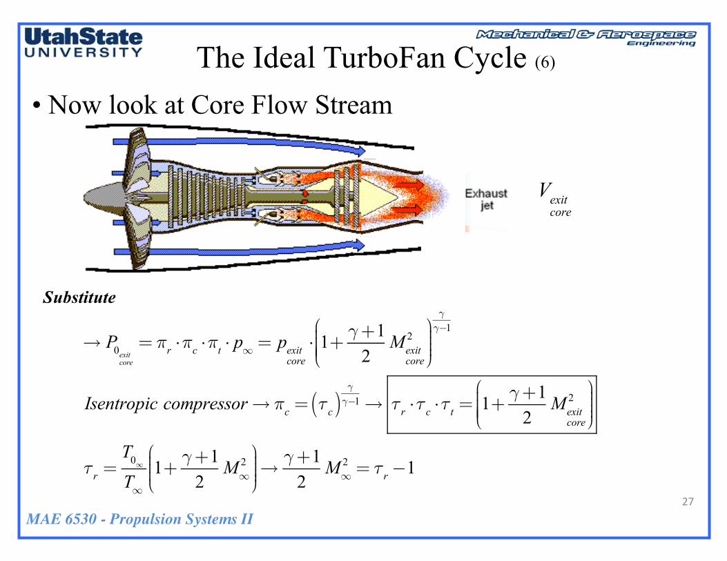
• Now look at Core Flow Stream
Substitute
Vexitcore
→ P0exitcore
= πr ⋅πc ⋅πt ⋅ p∞ = pexitcore⋅ 1+ γ+1
2Mexit
core
2⎛
⎝⎜⎜⎜⎜
⎞
⎠⎟⎟⎟⎟
γγ−1
Isentropic compressor→ πc = τc( )γγ−1→ τr ⋅τc ⋅τt = 1+ γ+1
2Mexit
core
2⎛
⎝⎜⎜⎜⎜
⎞
⎠⎟⎟⎟⎟
τr =T0∞
T∞1+ γ+1
2M∞
2⎛
⎝⎜⎜⎜
⎞
⎠⎟⎟⎟⎟→γ+1
2M∞
2 = τr−1
MAE 6530 - Propulsion Systems II
The Ideal TurboFan Cycle (7)
28
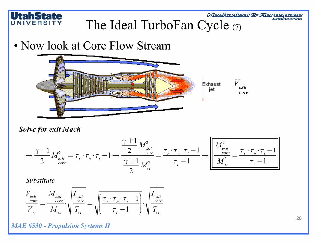
• Now look at Core Flow Stream
Solve for exit Mach
→γ+12Mexit
core
2 = τr ⋅τc ⋅τt−1→
γ+12Mexit
core
2
γ+12M∞
2=τr ⋅τc ⋅τt−1τr−1
→Mexit
core
2
M∞2 =
τr ⋅τc ⋅τt−1τr−1
Substitute
Vexitcore
V∞=Mexit
core
M∞⋅Texitcore
T∞=
τr ⋅τc ⋅τt−1τr−1
⎛
⎝⎜⎜⎜⎜
⎞
⎠⎟⎟⎟⎟⎟⋅Texitcore
T∞
Vexitcore

MAE 6530 - Propulsion Systems II
The Ideal TurboFan Cycle (8)
29
• Now look at Core Flow Stream
Calculate exit Stagnation Temperature
Calculate→T0exitcore
=T∞ ⋅T0∞
T∞⋅T02
core
T0∞
⋅T03
core
T02core
⋅T04
core
T03core
⋅T05
core
T04core
⋅T0exit
core
T05core
⎛
⎝
⎜⎜⎜⎜⎜⎜⎜
⎞
⎠
⎟⎟⎟⎟⎟⎟⎟⎟⎟=T∞ ⋅ τr ⋅τd ⋅τc ⋅τt ⋅τn( )
Isentropic nozzle→T0exitcore
=Texitcore⋅ 1+ γ+1
2Mexit
core
2⎛
⎝⎜⎜⎜⎜
⎞
⎠⎟⎟⎟⎟
From previous→ 1+ γ+12Mexit
core
2⎛
⎝⎜⎜⎜⎜
⎞
⎠⎟⎟⎟⎟= τr ⋅τc ⋅τt
→T0exitcore
=Texitcore⋅ τr ⋅τc ⋅τt( )
Vexitcore

MAE 6530 - Propulsion Systems II
The Ideal TurboFan Cycle (9)
30
• Now look at Core Flow Stream
Write in terms of maximum temperature ratio
Texitcore
T∞=T04
core
1+ γ+12M4
core
2⎛
⎝⎜⎜⎜⎜
⎞
⎠⎟⎟⎟⎟
T03core
1+ γ+12M3
core
2⎛
⎝⎜⎜⎜⎜
⎞
⎠⎟⎟⎟⎟
→ M4core≈ M3
core≈ 0→
Texitcore
T∞=T04
core
T03core
⋅T02
core
T0∞⋅T∞T∞=T04
core
T∞⋅T02
core
T03core
⋅T∞T0∞=τλτc ⋅τr
Texitcore
T∞=τλτc ⋅τr
→Vexitcore
V∞=
τr ⋅τc ⋅τt−1τr−1
⎛
⎝⎜⎜⎜⎜
⎞
⎠⎟⎟⎟⎟⎟⋅τλτc ⋅τr
→Vexitcore
V∞
⎛
⎝
⎜⎜⎜⎜⎜⎜⎜
⎞
⎠
⎟⎟⎟⎟⎟⎟⎟⎟
2
=τr ⋅τc ⋅τt−1τr−1
⎛
⎝⎜⎜⎜⎜
⎞
⎠⎟⎟⎟⎟⎟⋅τλτc ⋅τr
⎛
⎝⎜⎜⎜⎜
⎞
⎠⎟⎟⎟⎟⎟
Vexitcore

MAE 6530 - Propulsion Systems II
The Ideal TurboFan Cycle (10)
31
• Now look at Core Flow Stream
• Core Thrust
T( )core= γ ⋅M∞
2 11+β⎛
⎝⎜⎜⎜
⎞
⎠⎟⎟⎟⎟⋅
τr ⋅τc ⋅τt−1τr−1
⎛
⎝⎜⎜⎜⎜
⎞
⎠⎟⎟⎟⎟⎟⋅τλτc ⋅τr
⎛
⎝⎜⎜⎜⎜
⎞
⎠⎟⎟⎟⎟⎟−1
⎛
⎝
⎜⎜⎜⎜⎜
⎞
⎠
⎟⎟⎟⎟⎟⎟
⎡
⎣
⎢⎢⎢⎢
⎤
⎦
⎥⎥⎥⎥
Vexitcore
T( )turbofan
=Fthrustp∞A0
=!maV∞p∞A0
1+ f +βf 1+β( )
⋅Vexitcore
V∞+β1+β
⋅Vexitfan
V∞−1
⎡
⎣
⎢⎢⎢⎢
⎤
⎦
⎥⎥⎥⎥+pexitcore
p∞⋅Aexitcore
A0+pexitfan
p∞
Aexitfan
A0−Aexitcore+ Aexit
fan
A0
⎛
⎝
⎜⎜⎜⎜⎜⎜⎜
⎞
⎠
⎟⎟⎟⎟⎟⎟⎟⎟=
!maV∞p∞A0
=ρ∞ ⋅ A0 ⋅V∞ ⋅V∞
p∞A0=γV∞
2
γ ⋅Rg ⋅T∞= γ ⋅M∞
2
Aexitcore+ Aexit
fan= Aexit→
T( )turbofan
= γ ⋅M∞21+ 1
f1+β( )
1+β( )⋅Vexitcore
V∞+β1+β
⋅Vexitfan
V∞−1
⎡
⎣
⎢⎢⎢⎢⎢⎢
⎤
⎦
⎥⎥⎥⎥⎥⎥
+AexitA0
⎛
⎝⎜⎜⎜⎜
⎞
⎠⎟⎟⎟⎟⎟pexitp∞⋅Aexitcore
Aexit+pexitfan
p∞
Aexitfan
Aexit−1
⎛
⎝
⎜⎜⎜⎜⎜⎜⎜
⎞
⎠
⎟⎟⎟⎟⎟⎟⎟⎟

MAE 6530 - Propulsion Systems II
Fan/Core/Pressure Thrust Summary
• Fan
• Core
T( )core= γ ⋅M∞
2 11+β⎛
⎝⎜⎜⎜
⎞
⎠⎟⎟⎟⎟⋅
τr ⋅τc ⋅τt−1τr−1
⎛
⎝⎜⎜⎜⎜
⎞
⎠⎟⎟⎟⎟⎟⋅τλτc ⋅τr
⎛
⎝⎜⎜⎜⎜
⎞
⎠⎟⎟⎟⎟⎟−1
⎛
⎝
⎜⎜⎜⎜⎜
⎞
⎠
⎟⎟⎟⎟⎟⎟
⎡
⎣
⎢⎢⎢⎢
⎤
⎦
⎥⎥⎥⎥
T( )turbofan
=Fthrustp∞A0
=!maV∞p∞A0
1+ f +βf 1+β( )
⋅Vexitcore
V∞+β1+β
⋅Vexitfan
V∞−1
⎡
⎣
⎢⎢⎢⎢
⎤
⎦
⎥⎥⎥⎥+pexitcore
p∞⋅Aexitcore
A0+pexitfan
p∞
Aexitfan
A0−Aexitcore+ Aexit
fan
A0
⎛
⎝
⎜⎜⎜⎜⎜⎜⎜
⎞
⎠
⎟⎟⎟⎟⎟⎟⎟⎟=
!maV∞p∞A0
=ρ∞ ⋅ A0 ⋅V∞ ⋅V∞
p∞A0=γV∞
2
γ ⋅Rg ⋅T∞= γ ⋅M∞
2
Aexitcore+ Aexit
fan= Aexit→
T( )turbofan
= γ ⋅M∞21+ 1
f1+β( )
1+β( )⋅Vexitcore
V∞+β1+β
⋅Vexitfan
V∞−1
⎡
⎣
⎢⎢⎢⎢⎢⎢
⎤
⎦
⎥⎥⎥⎥⎥⎥
+AexitA0
⎛
⎝⎜⎜⎜⎜
⎞
⎠⎟⎟⎟⎟⎟pexitp∞⋅Aexitcore
Aexit+pexitfan
p∞
Aexitfan
Aexit−1
⎛
⎝
⎜⎜⎜⎜⎜⎜⎜
⎞
⎠
⎟⎟⎟⎟⎟⎟⎟⎟
The Ideal TurboFan Cycle (11)
32
Substitute
Vexitfan
V∞=Mexit
fan
M∞⋅Texitfan
T∞=
τr ⋅τcfan−1
τr−1
⎛
⎝
⎜⎜⎜⎜⎜⎜⎜
⎞
⎠
⎟⎟⎟⎟⎟⎟⎟⎟⋅Texitfan
T∞→ isentropic fan→ pexit
fan
⎛
⎝⎜⎜⎜⎜⎞
⎠⎟⎟⎟⎟
γ−1γ
= p∞( )γ−1γ
→Texitfan=T∞
Vexitfan
V∞
⎛
⎝
⎜⎜⎜⎜⎜⎜⎜
⎞
⎠
⎟⎟⎟⎟⎟⎟⎟⎟
2
=τr ⋅τc
fan−1
τr−1
⎛
⎝
⎜⎜⎜⎜⎜⎜⎜
⎞
⎠
⎟⎟⎟⎟⎟⎟⎟⎟→ T( )
fan= γ ⋅M∞
2 β1+β⎛
⎝⎜⎜⎜
⎞
⎠⎟⎟⎟⎟⋅Vexitfan
V∞−1
⎛
⎝
⎜⎜⎜⎜⎜⎜⎜
⎞
⎠
⎟⎟⎟⎟⎟⎟⎟⎟
⎡
⎣
⎢⎢⎢⎢⎢
⎤
⎦
⎥⎥⎥⎥⎥
= γ ⋅M∞2 β
1+β⎛
⎝⎜⎜⎜
⎞
⎠⎟⎟⎟⎟⋅τr ⋅τc
fan−1
τr−1−1
⎛
⎝
⎜⎜⎜⎜⎜⎜⎜⎜
⎞
⎠
⎟⎟⎟⎟⎟⎟⎟⎟⎟
⎡
⎣
⎢⎢⎢⎢⎢
⎤
⎦
⎥⎥⎥⎥⎥
Vexitfan
V∞
⎛
⎝
⎜⎜⎜⎜⎜⎜⎜
⎞
⎠
⎟⎟⎟⎟⎟⎟⎟⎟
2
=τr ⋅τc
fan−1
τr−1
⎛
⎝
⎜⎜⎜⎜⎜⎜⎜
⎞
⎠
⎟⎟⎟⎟⎟⎟⎟⎟
Vexitcore
V∞
⎛
⎝
⎜⎜⎜⎜⎜⎜⎜
⎞
⎠
⎟⎟⎟⎟⎟⎟⎟⎟
2
=τr ⋅τc ⋅τt−1τr−1
⎛
⎝⎜⎜⎜⎜
⎞
⎠⎟⎟⎟⎟⎟⋅τλτc ⋅τr
⎛
⎝⎜⎜⎜⎜
⎞
⎠⎟⎟⎟⎟⎟
MAE 6530 - Propulsion Systems II
Turbine-Compressor-Fan Work Matching
33
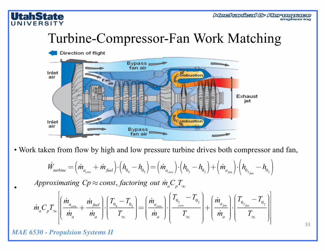
• Work taken from flow by high and low pressure turbine drives both compressor and fan,
•
!Wturbine = !macore + !mfuel( )⋅ h04 −h05( )= !macore( )⋅ h03−h02( )+ !mafan( )⋅ h03 fan −h02( )Approximating Cp≈ const, factoring out !maCpT∞
!maCpT∞!macore!ma+!mfuel
!ma
⎛
⎝
⎜⎜⎜⎜⎜
⎞
⎠
⎟⎟⎟⎟⎟⋅T04−T05
T∞
⎛
⎝
⎜⎜⎜⎜⎜
⎞
⎠
⎟⎟⎟⎟⎟=!macore!ma
⎛
⎝
⎜⎜⎜⎜⎜
⎞
⎠
⎟⎟⎟⎟⎟⋅T03
core
−T02
T∞
⎛
⎝
⎜⎜⎜⎜⎜⎜⎜
⎞
⎠
⎟⎟⎟⎟⎟⎟⎟⎟+!mafan!ma
⎛
⎝
⎜⎜⎜⎜⎜
⎞
⎠
⎟⎟⎟⎟⎟⎟⋅T03 fan−T02
T∞
⎛
⎝
⎜⎜⎜⎜⎜⎜
⎞
⎠
⎟⎟⎟⎟⎟⎟⎟
⎡
⎣
⎢⎢⎢⎢⎢
⎤
⎦
⎥⎥⎥⎥⎥

MAE 6530 - Propulsion Systems II
Turbine-Compressor-Fan Work Matching (2)
34
→ Simplify
1−B+ 1f
⎛
⎝⎜⎜⎜
⎞
⎠⎟⎟⎟⎟⋅T04T∞−T05T04
T04T∞
⎛
⎝
⎜⎜⎜⎜⎜
⎞
⎠
⎟⎟⎟⎟⎟⎟= 1−B( )⋅
T02T∞
T03core
T02−T02T∞
⎛
⎝
⎜⎜⎜⎜⎜⎜⎜
⎞
⎠
⎟⎟⎟⎟⎟⎟⎟⎟+
β1+β⎛
⎝⎜⎜⎜
⎞
⎠⎟⎟⎟⎟⋅T02T∞
T03fan
T02−T02T∞
⎛
⎝
⎜⎜⎜⎜⎜⎜⎜
⎞
⎠
⎟⎟⎟⎟⎟⎟⎟⎟
→ Substitute
τλ =T04T∞
τt =T04T∞
τr =T0∞T∞=T02T∞
T03core
T02= τc
core
T03fan
T02= τc
fan
⎡
⎣
⎢⎢⎢⎢⎢⎢⎢⎢⎢
⎤
⎦
⎥⎥⎥⎥⎥⎥⎥⎥⎥
→ 1−B+ 1f
⎛
⎝⎜⎜⎜
⎞
⎠⎟⎟⎟⎟⋅ τλ−τtτλ( )= 1−B( )⋅ τrτc
core−τr
⎛
⎝⎜⎜⎜⎜
⎞
⎠⎟⎟⎟⎟+
β1+β⎛
⎝⎜⎜⎜
⎞
⎠⎟⎟⎟⎟⋅ τrτcfan
−τr⎛
⎝⎜⎜⎜⎜
⎞
⎠⎟⎟⎟⎟
→ Solve for τt
τt =1−1−B( )⋅ τr
τλ⋅ τc
core−1
⎛
⎝⎜⎜⎜⎜
⎞
⎠⎟⎟⎟⎟+
β1+β⎛
⎝⎜⎜⎜
⎞
⎠⎟⎟⎟⎟⋅τrτλ⋅ τc
fan−1
⎛
⎝⎜⎜⎜⎜
⎞
⎠⎟⎟⎟⎟
1−B+ 1f
⎛
⎝⎜⎜⎜
⎞
⎠⎟⎟⎟⎟
MAE 6530 - Propulsion Systems II
Turbine-Compressor-Fan Work Matching (3)
35
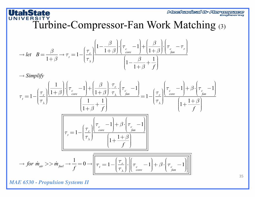
→ let B= β1+β
→ τt =1−τrτλ
⎛
⎝⎜⎜⎜⎜
⎞
⎠⎟⎟⎟⎟⎟
1− β1+β
⎛
⎝⎜⎜⎜
⎞
⎠⎟⎟⎟⎟⋅ τccore
−1⎛
⎝⎜⎜⎜⎜
⎞
⎠⎟⎟⎟⎟+
β1+β⎛
⎝⎜⎜⎜
⎞
⎠⎟⎟⎟⎟⋅ τcfan
−τr⎛
⎝⎜⎜⎜⎜
⎞
⎠⎟⎟⎟⎟
1− β1+β
+1f
⎛
⎝⎜⎜⎜
⎞
⎠⎟⎟⎟⎟
→ Simplify
τt =1−τrτλ
⎛
⎝⎜⎜⎜⎜
⎞
⎠⎟⎟⎟⎟⎟
11+β⎛
⎝⎜⎜⎜
⎞
⎠⎟⎟⎟⎟⋅ τccore
−1⎛
⎝⎜⎜⎜⎜
⎞
⎠⎟⎟⎟⎟+
β1+β⎛
⎝⎜⎜⎜
⎞
⎠⎟⎟⎟⎟⋅τrτλ⋅ τc
fan−1
⎛
⎝⎜⎜⎜⎜
⎞
⎠⎟⎟⎟⎟
11+β
+1f
⎛
⎝⎜⎜⎜
⎞
⎠⎟⎟⎟⎟
=1−τrτλ
⎛
⎝⎜⎜⎜⎜
⎞
⎠⎟⎟⎟⎟⎟
τccore−1
⎛
⎝⎜⎜⎜⎜
⎞
⎠⎟⎟⎟⎟+β ⋅ τc
fan−1
⎛
⎝⎜⎜⎜⎜
⎞
⎠⎟⎟⎟⎟
1+1+βf
⎛
⎝⎜⎜⎜
⎞
⎠⎟⎟⎟⎟
τt =1−τrτλ
⎛
⎝⎜⎜⎜⎜
⎞
⎠⎟⎟⎟⎟⎟
τccore−1
⎛
⎝⎜⎜⎜⎜
⎞
⎠⎟⎟⎟⎟+β ⋅ τc
fan−1
⎛
⎝⎜⎜⎜⎜
⎞
⎠⎟⎟⎟⎟
1+1+βf
⎛
⎝⎜⎜⎜
⎞
⎠⎟⎟⎟⎟
→ for !mair >> !mfuel→1f= 0→ τt =1−
τrτλ
⎛
⎝⎜⎜⎜⎜
⎞
⎠⎟⎟⎟⎟⎟⋅ τc
core−1
⎛
⎝⎜⎜⎜⎜
⎞
⎠⎟⎟⎟⎟+β ⋅ τrτc
fan−τr
⎛
⎝⎜⎜⎜⎜
⎞
⎠⎟⎟⎟⎟
⎡
⎣⎢⎢
⎤
⎦⎥⎥τt =1−
τrτλ
⎛
⎝⎜⎜⎜⎜
⎞
⎠⎟⎟⎟⎟⎟⋅ τc
core−1
⎛
⎝⎜⎜⎜⎜
⎞
⎠⎟⎟⎟⎟+β ⋅ τc
fan−1
⎛
⎝⎜⎜⎜⎜
⎞
⎠⎟⎟⎟⎟
⎡
⎣⎢⎢
⎤
⎦⎥⎥

MAE 6530 - Propulsion Systems II
Air to Fuel Ratio
36
→ Rearrange
!mfuel ⋅ hfuel−h04( )= !macore ⋅ h04
−h03core( )
→ factor out !maCp ⋅T∞
!maCp ⋅T∞!mfuel
!ma⋅hfuelCp ⋅T∞
−T04
T∞
⎛
⎝
⎜⎜⎜⎜⎜
⎞
⎠
⎟⎟⎟⎟⎟=!macore!ma⋅T04
T∞−T02core
T∞⋅T03core
T02core
⎛
⎝
⎜⎜⎜⎜⎜⎜
⎞
⎠
⎟⎟⎟⎟⎟⎟⎟
⎡
⎣
⎢⎢⎢⎢
⎤
⎦
⎥⎥⎥⎥
→ Simplify
1f⋅ τ fuel−τλ( )= 1
1+β⋅ τλ−τr ⋅τc
core
⎛
⎝⎜⎜⎜⎜
⎞
⎠⎟⎟⎟⎟→
1f=
11+β
⋅τλ−τr ⋅τc
core
τ fuel−τλ
⎛
⎝
⎜⎜⎜⎜⎜⎜⎜
⎞
⎠
⎟⎟⎟⎟⎟⎟⎟⎟
f = 1+β( )⋅τ fuel−τλτλ−τr ⋅τc
core
⎛
⎝
⎜⎜⎜⎜⎜⎜⎜
⎞
⎠
⎟⎟⎟⎟⎟⎟⎟⎟

MAE 6530 - Propulsion Systems II
Collected TurboFan Matching Equations
37
τt =1−τrτλ
⎛
⎝⎜⎜⎜⎜
⎞
⎠⎟⎟⎟⎟⎟
τccore−1
⎛
⎝⎜⎜⎜⎜
⎞
⎠⎟⎟⎟⎟+β ⋅ τc
fan−1
⎛
⎝⎜⎜⎜⎜
⎞
⎠⎟⎟⎟⎟
1+1+βf
⎛
⎝⎜⎜⎜
⎞
⎠⎟⎟⎟⎟
• Turbine Work
• Fuel/Air Flow f =!ma!mfuel
If the bypass ratio goes to zero the matching condition reduces to the usual turbojet formula.
1f=
11+β
⋅τλ−τr ⋅τc
core
τ fuel−τλ
⎛
⎝
⎜⎜⎜⎜⎜⎜⎜
⎞
⎠
⎟⎟⎟⎟⎟⎟⎟⎟
f = 1+β( )⋅τ fuel−τλτλ−τr ⋅τc
core
⎛
⎝
⎜⎜⎜⎜⎜⎜⎜
⎞
⎠
⎟⎟⎟⎟⎟⎟⎟⎟

MAE 6530 - Propulsion Systems II
Questions??
38


