December 27, 2010 Draft Page 6H-1 Section 6H.01 Typical Applications Support: 01 Whenever the acronym “TTC” is used in this Chapter, it refers to “temporary traffic control”. Standard: 02 The needs and control of all road users (motorists, bicyclists, motorcyclists, and pedestrians within the highway, including persons with disabilities in accordance with the Americans with Disabilities Act of 1990 (ADA), Title II, Paragraph 35.130) through a TTC zone shall be an essential part of highway construction, utility work, maintenance operations, and the management of traffic incidents. Support: 03 Chapter 6G contains discussions of typical TTC activities. Chapter 6H presents typical applications for a variety of situations commonly encountered. While not every situation is addressed, the information illustrated can generally be adapted to a broad range of conditions. In many instances, an appropriate TTC plan is achieved by combining features from various typical applications. For example, work at an intersection might present a near-side work zone for one street and a far-side work zone for the other street. These treatments are found in two different typical applications, while a third typical application shows how to handle pedestrian crosswalk closures. For convenience in using the typical application diagrams, Tables 6C-4, 6C-2, 6F-1, and 6C-1 are reproduced in this Chapter as Tables 6H-2, 6H-3, 6H-4, and 6H-5, respectively. 04 Procedures for establishing TTC zones vary with such conditions as road configuration, location of the work, work activity, duration of work, road user volumes, road vehicle mix (buses, trucks, cars, motorcycles, and bicycles), and road user speeds. Examples are presented in this Chapter showing how to apply principles and standards. Applying these guidelines to actual situations and adjusting to field conditions requires judgment. In general, the procedures illustrated represent minimum solutions for the situations depicted. Option: 05 Other devices may be added to supplement the devices and device spacing may be adjusted to provide additional reaction time or delineation. Fewer devices may be used based on field conditions. Support: 06 Figures and tables found throughout Part 6 provide information for the development of TTC plans. Table 6H-2 is used for the determination of taper lengths, Table 6H-3 for buffer lengths and flagger placement. 07 Table 6H-1 is an index of the 61 Typical Traffic Control (TTC) figures. Typical traffic control figures are shown on the right page with notes on the facing page to the left. The legend for the symbols used in the TTC figures is provided in Figure 6H-1. In many of the typical applications, sign spacings and other dimensions are indicated in the notes to the left of the figure. 08 Most of the typical applications show TTC devices for only one direction. 09 The following TTC applications illustrate mobile, short duration, short-term and intermediate-term stationary work activities utilizing portable (self-erecting) sign stands placed on the shoulder. Standard: 10 For long-term stationary work activities or as directed by the engineer, post mounted signs placed outside of the shoulder per Figure 6F-1 shall be required.
Transcript
December 27, 2010 Draft Page 6H-1
Section 6H.01 Typical Applications Support:
01 Whenever the acronym “TTC” is used in this Chapter, it refers to “temporary traffic control”. Standard:
02 The needs and control of all road users (motorists, bicyclists, motorcyclists, and pedestrians within the highway, including persons with disabilities in accordance with the Americans with Disabilities Act of 1990 (ADA), Title II, Paragraph 35.130) through a TTC zone shall be an essential part of highway construction, utility work, maintenance operations, and the management of traffic incidents. Support:
03 Chapter 6G contains discussions of typical TTC activities. Chapter 6H presents typical applications for a variety of situations commonly encountered. While not every situation is addressed, the information illustrated can generally be adapted to a broad range of conditions. In many instances, an appropriate TTC plan is achieved by combining features from various typical applications. For example, work at an intersection might present a near-side work zone for one street and a far-side work zone for the other street. These treatments are found in two different typical applications, while a third typical application shows how to handle pedestrian crosswalk closures. For convenience in using the typical application diagrams, Tables 6C-4, 6C-2, 6F-1, and 6C-1 are reproduced in this Chapter as Tables 6H-2, 6H-3, 6H-4, and 6H-5, respectively.
04 Procedures for establishing TTC zones vary with such conditions as road configuration, location of the work, work activity, duration of work, road user volumes, road vehicle mix (buses, trucks, cars, motorcycles, and bicycles), and road user speeds. Examples are presented in this Chapter showing how to apply principles and standards. Applying these guidelines to actual situations and adjusting to field conditions requires judgment. In general, the procedures illustrated represent minimum solutions for the situations depicted. Option:
05 Other devices may be added to supplement the devices and device spacing may be adjusted to provide additional reaction time or delineation. Fewer devices may be used based on field conditions. Support:
06 Figures and tables found throughout Part 6 provide information for the development of TTC plans. Table 6H-2 is used for the determination of taper lengths, Table 6H-3 for buffer lengths and flagger placement.
07 Table 6H-1 is an index of the 61 Typical Traffic Control (TTC) figures. Typical traffic control figures are shown on the right page with notes on the facing page to the left. The legend for the symbols used in the TTC figures is provided in Figure 6H-1. In many of the typical applications, sign spacings and other dimensions are indicated in the notes to the left of the figure.
08 Most of the typical applications show TTC devices for only one direction. 09 The following TTC applications illustrate mobile, short duration, short-term and intermediate-term
stationary work activities utilizing portable (self-erecting) sign stands placed on the shoulder. Standard: 10 For long-term stationary work activities or as directed by the engineer, post mounted signs placed
outside of the shoulder per Figure 6F-1 shall be required.
Page 6H-2 December 27, 2010 Draft
Table 6H-1, Index to Typical Temporary Traffic Control Figures and Notes
Type of Operation Figure Number Page Numbers
Work Outside the Shoulder
Work Beyond the Shoulder Operation TTC-1.0 6H-8, 6H-9
Blasting Zone Operation TTC-2.0 6H-10, 6H-11
Work On the Shoulder
Mobile or Short Duration on Shoulder Operation TTC-3.0 6H-12, 6H-13
Stationary Operation on Shoulder TTC-4.0 6H-14, 6H-15
Shoulder Operation with Minor Encroachment TTC-5.0 6H-16, 6H-17
Shoulder Closure with Barrier Operation TTC-6.0 6H-18, 6H-19
Shoulder Closure with Barrier and Lane Shift Operation
TTC-7.0 6H-20, 6H-21
Pull-Off Areas on Limited Access Highway and Expressway Work Zones TTC-8.0 6H-22, 6H-23
Mowing Operation with Encroachment on Non-Limited Access Roadway TTC-9.0 6H-24, 6H-25
Non-License Vehicle Operation with Encroachment on Limited Access Roadway TTC-10.0 6H-26, 6H-27
Work Within the Travelway
Moving/Mobile Operations on Limited Access Highway (Single Lane Closure) TTC-11.0 6H-28, 6H-29
Moving/Mobile Operations on Limited Access Highway (Multiple Lane Closures) TTC-12.0 6H-30, 6H-31
Moving/Mobile Operations on Multi-Lane Roadway TTC-13.0 6H-32, 6H-33
Moving/Mobile Operations on Two-Lane Roadway TTC-14.0 6H-34, 6H-35
Short Duration Operation on Multi-Lane Roadway TTC-15.0 6H-36, 6H-37
Outside Lane Closure Operation on Four-Lane Roadway TTC-16.0 6H-38, 6H-39
Inside Lane Closure Operation on Four-Lane Roadway TTC-17.0 6H-40, 6H-41
Table 6H-3, Buffer Space/ Flagger Distance from Work Area
Page 6H-6 December 27, 2010 Draft
Posted Speed (mph) Location
0 - 35 36 +
Transition Spacing 20' 40'
Travelway Spacing 40' 80'
Spot Construction Access * 80' 120' * For easier access by construction vehicles into the work area, spacing of devices may be increased to this distance, but shall not exceed one access per 0.25 mile unless approved by the engineer and documented.
Table 6H-4, Channelizing Device Spacing
Urban street with 25 mph or less posted speed * 100' - 200'
Urban street with 30 to 35 mph posted speed * 225' - 275'
Roadways with 45 mph or less posted speed 350'- 500'
Roadways with greater than 45 mph posted speed 500'- 800'
Limited Access Highways 1300' - 1500'
* Note: For urban conditions, it is generally better to place all advanced warning signs within a one block area versus spreading out the signs over several blocks, however, motorist must have time to recognize and react to each warning sign see Section 6G.11.
Table 6H-5, Advance Warning Sign Spacing
December 27, 2010 Draft Page 6H-7
Figure 6H-1, Symbols Used In Typical Temporary Traffic Control Figures Application
Page 6H-8 December 27, 2010 Draft
Typical Traffic Control Work Beyond the Shoulder
(Figure TTC-1.0) NOTES
Guidance: 1. The minimum distance between sign and work vehicle should be 1300'-1500' on Limited Access
Highways, and on all other roadways 500'-800' where the posted speed limit is greater than 45 mph, and 350'-500' where the posted speed limited is 45 mph or less.
Option: 2. The ROAD WORK AHEAD (W20-1) sign may be replaced with other appropriate signs such as the
SHOULDER WORK (W21-5) sign. The SHOULDER WORK sign may be used for work adjacent to the shoulder.
3. The ROAD WORK AHEAD sign may be omitted where the work space is behind a barrier, more than 4 feet behind vertical curb (Standard CG-2 and CG-6) on urban roadways, or outside of the Clear Zone for all other roadways. For Clear Zone values, see Appendix A, Page A-4.
4. For short-term, short duration or mobile operation, all signs and channelizing devices may be eliminated if a vehicle with activated high-intensity amber rotating, flashing, oscillating, or strobe lights is used.
Standard: 5. Vehicle hazard warning signals shall not be used instead of the vehicle’s high-intensity amber
rotating, flashing, oscillating, or strobe lights. Vehicle hazard warning signals can be used to supplement high-intensity amber rotating, flashing, oscillating, or strobe lights.
6. If the work space is in the median of a divided highway, an advance warning sign shall also be placed on the left side of the directional roadway.
December 27, 2010 Draft Page 6H-9
Work Beyond the Shoulder (Figure TTC-1.0)
Page 6H-10 December 27, 2010 Draft Typical Traffic Control Blasting Zone Operation
(Figure TTC-2.0) NOTES
Standard: 1. Whenever blasting caps are used within 1000 feet of a roadway, the signing shown shall be used. 2. Sign spacing distance shall be a minimum of 1000 feet from the blasting area. 3. The signs shall be covered or removed when there are no explosives in the area or the area is
otherwise secure. 4. Whenever a side road intersects the roadway between the BLASTING ZONE AHEAD (W22-1)
sign and the END BLASTING ZONE (W22-3) sign, or a side road is within 1000 feet of any blasting cap, similar signing, as on the mainline, shall be installed on the side road.
5. Prior to blasting, the blaster in charge shall determine whether road users in the blasting zone will be endangered by the blasting operation. If there is danger, road users shall not be permitted to pass through the blasting zone during blasting operations.
6. On divided highways having a median wider than 8', right and left sign assemblies shall be required.
Guidance: 7. On a divided highway, the signs should be mounted on both sides of the directional roadways. 8. Spacing between signs should be 1300'-1500' for Limited Access Highways. For all other roadways,
the sign spacing should be 500'-800' where the posted speed limit is greater than 45 mph, and 350'-500' where the posted speed limit is 45 mph or less.
December 27, 2010 Draft Page 6H-11
Blasting Zone Operation (Figure TTC-2.0)
Page 6H-12 December 27, 2010 Draft Typical Traffic Control
Mobile or Short Duration Shoulder Operation (Figure TTC-3.0)
NOTES Guidance:
1. In those situations where multiple work locations within a limited distance make it practical to place stationary signs, the distance between the advance warning sign and the work should not exceed 5 miles.
2. The ROAD WORK NEXT 2 MILES (W21-V2) sign should be used instead of the ROAD WORK AHEAD (W20-1) sign if the work locations occur over a distance of more than 2 miles.
Option: 3. Stationary warning signs may be omitted for short duration or mobile operations if the work vehicle
displays high-intensity rotating, flashing, oscillating, or strobe lights. Standard:
4. Vehicle hazard warning signals shall not be used instead of the vehicle’s high-intensity amber rotating, flashing, oscillating, or strobe lights. Vehicle hazard warning signals can be used to supplement high-intensity amber rotating, flashing, oscillating, or strobe lights.
5. If an arrow board is used for an operation on the shoulder, the caution mode shall be used. 6. Vehicle mounted signs shall be mounted in a manner such that they are not obscured by
equipment or supplies. Sign legends on vehicle mounted signs shall be covered or turned from view when work is not in progress.
7. The shadow vehicle with a truck mounted attenuator (TMA) shall be used on Limited Access Highways.
8. If multiple work crews are active at various locations throughout the 2 mile work zone, a shadow vehicle shall be used for each work crew.
December 27, 2010 Draft Page 6H-13
Mobile or Short Duration Shoulder Operation (Figure TTC-3.0)
Page 6H-14 December 27, 2010 Draft
Typical Traffic Control Stationary Operation on Shoulder
(Figure TTC-4.0) NOTES
Guidance: 1. A ROAD WORK AHEAD (W20-1)sign or SHOULDER WORK (W21-5) sign should be placed on the
left side of the roadway for a divided roadway or one-way street. 2. Sign spacing should be 1300'-1500' for Limited Access Highways. For all other roadways, the sign
spacing should be 500'-800' where the posted speed limit is greater than 45 mph, and 350'-500' where the posted speed limit is 45 mph or less.
Option: 3. The SHOULDER WORK sign on an intersecting roadway may be omitted where drivers emerging from
that roadway will encounter another advance warning sign prior to this activity area. 4. For short duration operations of 60 minutes or less, all signs and channelizing devices may be
eliminated if a vehicle with activated high-intensity amber rotating, flashing, oscillating, or strobe lights is used.
Standard: 5. Vehicle hazard warning signals shall not be used instead of the vehicle’s high-intensity amber
rotating, flashing, oscillating, or strobe lights. Vehicle hazard warning signals can be used to supplement high-intensity amber rotating, flashing, oscillating, or strobe lights.
6. Channelizing device spacing shall be at the following:
Shoulder Taper = ⅓ L Minimum Minimum lane closure taper length on all Limited Access Highways, regardless of posted speed, shall be 1000 feet.
8. The buffer space length shall be as shown in Table 6H-3, Page 6H-5, for the posted speed limit. 9. A truck mounted attenuator (TMA) shall be used on Limited Access Highways and multi-lane
roadways with posted speed limit equal to or greater than 45 mph. 10. When a side road intersects the highway within the temporary traffic control zone, additional
traffic control devices shall be placed as needed.
December 27, 2010 Draft Page 6H-15
Stationary Operation on Shoulder (Figure TTC-4.0)
Page 6H-16 December 27, 2010 Draft Typical Traffic Control
Shoulder Operation with Minor Encroachment (Figure TTC-5.0)
NOTES Guidance:
1. A ROAD WORK AHEAD (W20-1) sign or SHOULDER WORK (W21-5) sign should be placed on the left side of the roadway for a divided roadway with an 8' median or one-way street.
2. Sign spacing should be 1300'-1500' for Limited Access Highways. For all other roadways, the sign spacing should be 500'-800' where the posted speed limit is greater than 45 mph, and 350'-500' where the posted speed limit is 45 mph or less.
3. When work takes up part of a lane on a high volume roadway; vehicular traffic volumes, vehicle mix, speed and capacity should be analyzed to determine whether the affect lane should be closed. Unless the lane encroachment analysis permits a remaining lane width of 10 feet, the lane should be closed. If the closure operation is on a Limited Access Highway, the minimum lane width is 11 feet.
Option: 4. The ROAD WORK AHEAD sign on an intersecting roadway may be omitted where drivers emerging
from that roadway will encounter another advance warning sign prior to this activity area. Standard:
5. A shadow vehicle with either an arrow board operating in the caution mode, or at least one high-intensity amber rotating, flashing, oscillating, or strobe light shall be parked 80' - 120' in advance of the first work crew.
6. Vehicle hazard warning signals shall not be used instead of the vehicle’s high-intensity amber rotating, flashing, oscillating, or strobe lights. Vehicle hazard warning signals can be used to supplement high-intensity amber rotating, flashing, oscillating, or strobe lights.
7. Channelizing device spacing shall be at the following:
Shoulder Taper = ⅓ L Minimum Minimum lane closure taper length on all Limited Access Highways, regardless of posted speed, shall be 1000 feet.
9. The buffer space length shall be as shown in Table 6H-3, Page 6H-5, for the posted speed limit. 10. A truck mounted attenuator (TMA) shall be used on Limited Access Highways and multi-lane
roadways with posted speed limit equal to or greater than 45 mph. 11. When a side road intersects the highway within the temporary traffic control zone, additional
traffic control devices shall be placed as needed.
December 27, 2010 Draft Page 6H-17
Shoulder Operation with Minor Encroachment (Figure TTC-5.0)
Page 6H-18 December 27, 2010 Draft Typical Traffic Control
Shoulder Closure with Barrier Operation (Figure TTC-6.0)
NOTES Guidance:
1. Sign spacing should be 1300'-1500' for Limited Access Highways. For all other roadways, the sign spacing should be 500'-800' where the posted speed limit is greater than 45 mph, and 350'-500' where the posted speed limit is 45 mph or less.
Standard: 2. On divided highways having a median wider than 8', right and left sign assemblies shall be
required. 3. Group 2 channelizing device spacing shall be at the following:
4. The minimum length for a shoulder taper should be 300' on Limited Access Highways, and ⅓ L for all other roadways (see Note 7, TTC-5 for values of L).
5. Barrier transition slope ratio shall be as follows:
When the barrier transition slope is on a horizontal alignment, the total offset shall be prorated around the curve in lieu of a straight-line slope.
6. End treatment of a barrier in order of preference: a. Where guardrail exists, attach to barrier with appropriate fixed object attachment. b. Where cut slope exists, bury barrier into cut slope and provide for drainage as needed. c. Extend end of barrier until it is beyond the established clear zone (see Appendix A, Figure
2, Page A-4 for clear zone values). d. When barrier end is inside the established clear zone, attenuator service Type I or Type II
shall be used. Contact L&D Standards/Special Design Section for approved attenuators. 7. Barrier vertical panels 8 inches in width and 12 inches in height shall be placed on top of the
concrete barrier and spaced 80' on centers along the parallel or tangent sections and 40' on centers along the transition or taper sections. Reflectorized surface shall be fluorescent orange prismatic lens sheeting. The light at the beginning of the barrier run and at the breakpoint where the barrier becomes parallel to the roadway shall be a Type B flashing light. Barrier delineators shall be installed along the traffic side of the concrete barrier in accordance with Section 702 of VDOT’s Road and Bridge Specifications.
Option: 8. The barrier shown in this typical application is an example of one method that may be used to close a
shoulder of a long-term project. 9. The RIGHT SHOULDER CLOSED (W21-5a) sign may be eliminated from all roadways except
Limited Access Highways. Guidance:
10. If drivers cannot see a pull-off area beyond the closed shoulder, information regarding the length of the shoulder closure shall be provided in feet or miles, as appropriate.
11. An emergency pull-off area should be provided per Section 6G.17 and Temporary Traffic Control Figure TTC-8.
December 27, 2010 Draft Page 6H-19
Shoulder Closure with Barrier Operation (Figure TTC-6.0)
Page 6H-20 December 27, 2010 Draft Typical Traffic Control
Shoulder Closure with Barrier and Lane Shift Operation (Figure TTC-7.0)
NOTES Guidance:
1. The lane shift should be used when the work space extends into either the right or left lane of a divided highway and it is not practical, for capacity reasons, to reduce the number of available lanes.
2. When a lane shift is accomplished by using: (1) geometry that meets the design speed at which the permanent highway was designed, (2) full normal cross-section (full lane width and full shoulders), and (3) complete pavement markings, then the REVERSE CURVE (1-4bL) signs are not required.
3. Sign spacing distance should be 1300'-1500' for Limited Access Highways. For all other roadways, the sign spacing should be 500'-800' where the posted speed limit is greater than 45 mph, and 350'-500' where the posted speed limit is 45 mph or less.
Standard: 4. On divided highways having a median wider than 8', right and left sign assemblies shall be
required. 5. Length of pavement marking transition (L) is equal to posted speed (S) times the width of
transition (W) (Example: 55 mph x 2' = 110'). 6. Channelizing device spacing shall be at the following:
7. For end treatment of the barrier in order of preference see Note 6 of TTC-6. 8. Barrier vertical panel 8 inches in width and 12 inches in height shall be placed on top of the
concrete barrier and spaced 80' on centers along the parallel or tangent sections and 40' on centers along the transition or taper sections. Reflectorized surface shall be fluorescent orange prismatic lens sheeting. The light at the beginning of the barrier run and at the breakpoint where the barrier becomes parallel to the roadway shall be a Type B flashing light. Barrier delineators shall be installed along the traffic side of the concrete barrier in accordance with Section 702 of VDOT’s Road and Bridge Specifications.
9. Unless approved by the Regional Traffic Engineer, the minimum width of the travel lanes shall be 11 feet.
10. For long-term work zones existing conflicting pavement markings and markers shall be removed and temporary pavement markings and markers shall be installed per TTC-60.
Option: 11. Temporary pavement may be needed to maintain traffic with 11' minimum width lanes.
Guidance: 12. Eradication of existing pavement markings should be as shown in Typical Traffic Control Figure TTC-
54. 13. If drivers cannot see a pull-off area beyond the closed shoulder, information regarding the length of the
shoulder closure should be provided in feet or miles, as appropriate. 14. An emergency pull-off area should be provided per Section 6G.17 and Temporary Traffic Control
Figure TTC-8.
December 27, 2010 Draft Page 6H-21
Shoulder Closure with Barrier and Lane Shift Operation (Figure TTC-7.0)
Page 6H-22 December 27, 2010 Draft Typical Traffic Control
Pull-Off Area on Limited Access Highways (Figure TTC-8.0)
NOTES Guidance:
1. Work zone pull-off areas should be provided in work zones along Limited Access Highways and expressways where one or both shoulders are closed due to construction.
Option: 2. Work zone pull-off areas may be considered in work zones for other roadways where one or both
shoulders are closed due to construction. Guidance:
3. The spacing of pull-off areas should be as follows: • For projects with activity areas up to 2.0 miles in length, one every 0.5 to 0.75 mile. • For projects with activity areas greater than 2.0 miles in length, one every mile.
4. Pull-off areas should be a minimum of 1320 feet long. The width of pull-off areas should be a desirable distance of 15 feet.
Option: 5. The width of the work zone pull-off areas may be reduced to a minimum of 12 feet on roadways with
Right-of-Way constraints. Guidance:
6. Advance warning signs should be placed as follows: a. A NEXT X MILES (W16-VP1) supplemental plate should be provided with the first SHOULDER
CLOSED AHEAD (W21-5b) sign in the sequence. b. The second SHOULDER CLOSED AHEAD sign in the sequence should be replaced with either:
• A NO PULL OFF AREA (W21-V14) sign with NEXT X MILES supplemental plate, if there are no pull off areas throughout the work area, or
• A PULL OFF AREA (E5-V2) sign with EVERY X MILES (W16-VP2) supplemental plate, if pull off areas are provided.
c. Additional advance warning signs should be placed immediately prior to the pull-off area to give information to help a driver navigate to it safely. Additional options for the supplemental sign panel below PULL OFF AREA (E5-V2) that could be considered for these locations include a distance message appropriate for the design speed of the roadway (for example 500 FT or 1000 FT), NEXT EXIT, EXIT XX, NEXT LEFT or NEXT RIGHT (see Section 6F.35).
d. A PULL OFF AREA/NEXT EXIT (W21-V12/W16-VP4) signing should be provided within 0.5 mile of a limited access interchange exit if the exit is clearly signed and the interchange facilities provide adequate places for refuge.
7. Sign spacing should be 1300'-1500' for Limited Access Highways. Standard:
8. Minimum lane closure taper length on all Limited Access Highways, regardless of posted speed, shall be 1000 feet. Minimum shoulder taper length of Limited Access Highways shall be 300 feet.
9. Barrier vertical panels 8 inches in width and 12 inches in height shall be placed on top of the concrete barrier and spaced 80' on centers along the parallel or tangent sections and 40' on centers along the transition or taper sections. Reflectorized surface shall be flourescent orange prismatic lens sheeting. The light at the beginning of the barrier run and at the breakpoint where the barrier becomes parallel to the roadway shall be a Type B flashing light. Barrier delineators shall be installed along the traffic side of the concrete barrier in accordance with Section 702 of VDOT’s Road and Bridge Specifications.
December 27, 2010 Draft Page 6H-23
Pull-Off Areas on Limited Access Highways (Figure TTC-8.0)
Page 6H-24 December 27, 2010 Draft Typical Traffic Control
Mowing Operation with Encroachment on Non Limited Access Roadways (Figure TTC-9.0)
NOTES Standard:
1. Each vehicle involved in the operation shall be equipped with at least one rotating amber light or high intensity amber strobe or oscillating light visible from 360°.
2. On divided highways having a median wider than 8', right and left sign assemblies shall be required.
3. Connecting roads entering into the work area shall be signed as shown. 4. All vehicles traveling at speeds below 30 mph shall display a slow moving vehicle emblem per
OHSA regulation 1910.145(d)(10). Guidance:
5. Sign spacing distance should be 350'-500' where the posted speed limit is 45 mph or less, and 500'-800' where the posted speed limit is greater than 45 mph.
6. No more than 2 complete setups (2 miles each) should be exposed to motorist at any one time. 7. To prevent multiple lane changing by motorists and constriction of traffic flow, mowing operations
should be limited to one side of the roadway at a time, or separated by a minimum of 1000 feet between right and left side operations.
Mowing Operation with Encroachment on Non Limited Access Roadways (Figure TTC-9.0)
Page 6H-26 December 27, 2010 Draft Typical Traffic Control
Non-License Vehicle Operation with Encroachment on Limited Access Highways (Figure TTC-10.0)
NOTES Standard:
1. Each vehicle involved in the operation shall be equipped with at least one rotating amber light or high intensity amber strobe or oscillating light visible from 360°.
2. On divided highways having a median wider than 8', right and left sign assemblies shall be required.
3. Entrance ramps within the work area shall be signed as shown. 4. All vehicles traveling at speeds below 30 mph shall display a slow moving vehicle emblem per
OHSA regulation 1910.145(d)(10). Guidance:
5. Sign spacing distance should be 1300'-1500' on Limited Access Highways. 6. No more than 2 complete setups (2 miles each) should be exposed to motorist at any one time. 7. To prevent multiple lane changing by motorists and constriction of traffic flow, mowing operations
should be limited to one side of the roadway at a time, or separated by a minimum of 1000 feet between right and left side operations.
Option: 8. If the work operations vehicle is a motorized piece of equipment, such as a motor grader, grade-all, etc.,
the illuminated flashing arrow may be deleted. 9. The vehicle static warning sign and arrow panel may be replaced with a vehicle mounted CMS with a
minimum character height of 10". The arrow display using a CMS may be a Type B. Arrow direction and lane designation may change as needed.
10. The Shadow Vehicle 2 may be eliminated if the operation does not encroach in the travel lane. Standard:
11. If Shadow Vehicle 1 cannot run completely on the shoulder out of the travel lane and would be partially in the travel lane, it shall be equipped with a truck mounted attenuator.
Non-License Vehicle Operation with Encroachment on Limited Access Highways (Figure TTC-10.0)
Page 6H-28 December 27, 2010 Draft Typical Traffic Control
Moving/Mobile Operations on Limited Access Highways (Single Lane Closure) (Figure TTC-11.0)
NOTES Standard:
1. Each vehicle involved in the moving/mobile operation shall be equipped with at least one high-intensity amber rotating, oscillating, or strobe light. Illuminated flashing arrows on the advance warning vehicles shall be Type C (96" x 48"), and on the work operations vehicle a Type B (60" x 30") or Type C.
2. Vehicle hazard warning signals shall not be used instead of the vehicle’s high-intensity amber rotating, flashing, oscillating, or strobe lights. Vehicle hazard warning signals can be used to supplement high-intensity amber rotating, flashing, oscillating, or strobe lights.
Option: 3. If the work operations vehicle is a motorized piece of equipment, such as a motor grader, grade-all, etc.,
the illuminated flashing arrow may be deleted. 4. The static warning sign and arrow panel may be replaced with a vehicle mounted CMS with a minimum
character height of 10". The arrow display using a CMS may be a Type B. Arrow direction and lane designation may change as needed.
Standard: 5. Shadow Vehicle 1 shall travel along the paved shoulder with either a flashing arrow, or a portable
changeable message sign with 18" high characters advising of the operation ahead (LINE PAINTING AHEAD), and lane closure information (RIGHT LANE CLOSED, MERGE LEFT). Shadow Vehicle 2, with a truck mounted attenuator (TMA), shall either straddle the edgeline, partially on the shoulder and partially in the lane, or travel fully in the travel lane. Shadow Vehicle 3, with a TMA, shall be in the travel lane.
6. If Shadow Vehicle 1 cannot run completely on the shoulder out of the travel lane and would be partially in the travel lane, it shall be equipped with either a truck mounted attenuator or follow option in Note 7.
Option: 7. When Shadow Vehicle 1 cannot run completely on the shoulder, it may be replaced with a PCMS with
the messages in Note 4 displayed, or with a static warning sign with the appropriate message (LINE PAINTING NEXT 2 MILES). For inside lane closure operations, the Shadow Vehicle 1 may be positioned on the right shoulder without arrow designation.
Standard: 8. Each vehicle involved in the moving operation shall have radio communication between vehicles. 9. When the work operations vehicle is stationary, Shadow Vehicle 4 following the operations vehicle
shall be in a position 80'-120' in advance of the work operations vehicle to provide protection. When the work operations vehicle is moving, the Shadow Vehicle 4 following the operations vehicle shall follow at a distance of 240'± .
Guidance: 10. Spacing between vehicles may vary, depending on the speed, sight distance, and type of operation.
Whenever adequate stopping sight distance exists to the rear, the shadow vehicle should maintain the minimum distance and proceed at the same speed as the work operation vehicle. The shadow vehicle should slow down in advance of vertical or horizontal curves that restrict sight distance.
11. When using a CMS to replace the static sign and arrow panel, each word message phase should be followed by the Type B arrow display.
December 27, 2010 Draft Page 6H-29
Moving/Mobile Operations on Limited Access Highways (Single Lane Closure) (Figure TTC-11.0)
Page 6H-30 December 27, 2010 Draft Typical Traffic Control
Moving/Mobile Operations on Limited Access Highways (Multiple Lane Closure) (Figure TTC-12.0)
NOTES Standard:
1. Each vehicle involved in the moving/mobile operation shall be equipped with at least one high-intensity amber rotating, oscillating, or strobe light. Illuminated flashing arrows on the advance warning vehicles shall be Type C (96" x 48"), and on the work operations vehicle a Type B (60" x 30") or Type C.
2. Vehicle hazard warning signals shall not be used instead of the vehicle’s high-intensity amber rotating, flashing, oscillating, or strobe lights. Vehicle hazard warning signals can be used to supplement high-intensity amber rotating, flashing, oscillating, or strobe lights.
Option: 3. If the work operations vehicle is a motorized piece of equipment, such as a motor grader, grade-all, etc.,
the illuminated flashing arrow may be deleted. 4. The static warning sign and arrow panel may be replaced with a vehicle mounted CMS with a minimum
character height of 10". The arrow display using a CMS may be a Type B. Arrow direction and lane designation may change as needed.
Standard: 5. Shadow Vehicle 1 shall travel along the paved shoulder with either a flashing arrow, or a portable
changeable message sign with 18" high characters advising of the operation ahead (LINE PAINTING AHEAD), and lane closure information (RIGHT LANE CLOSED, MERGE LEFT). Shadow Vehicle 2, with a truck mounted attenuator (TMA), shall either straddle the edgeline, partially on the shoulder and partially in the lane, or travel fully in the travel lane.
6. If Shadow Vehicle 2 cannot run completely on the shoulder out of the travel lane and would be partially in the travel lane, it shall be equipped with either a truck mounted attenuator or follow option in Note 7.
Option: 7. When Shadow Vehicle 2 cannot run completely on the shoulder, it may be replaced with a PCMS with
the messages in Note 4 displayed, or with a static warning sign with the appropriate message (LINE PAINTING NEXT 2 MILES). For inside lane closure operations, the Shadow Vehicle 2 may be positioned on the right shoulder without arrow designation.
Standard: 8. Shadow Vehicles 3 and 4, with a TMA, shall be in their respective travel lane. 9. When the work operations vehicle is stationary, Shadow Vehicle 4 following the operations vehicle
shall be in a position 80'-120' in advance of the work operations vehicle to provide protection. When the work operations vehicle is moving, the Shadow Vehicle 4 following the operations vehicle shall follow at a distance of 240'± .
10. Each vehicle involved in the moving operation shall have radio communication between vehicles. Guidance:
11. Spacing between vehicles may vary, depending on the speed, sight distance, and type of operation. Whenever adequate stopping sight distance exists to the rear, the shadow vehicle should maintain the minimum distance and proceed at the same speed as the work operation vehicle. The shadow vehicle should slow down in advance of vertical or horizontal curves that restrict sight distance.
12. When using a CMS to replace the static sign and arrow panel, each word message phase should be followed by the Type B arrow display.
13. Section 6G-02 should be referenced for information on vehicle spacing for application on other classification of roadways.
December 27, 2010 Draft Page 6H-31
Moving/Mobile Operations on Limited Access Highways (Multiple Lane Closure) (Figure TTC-12.0)
Page 6H-32 December 27, 2010 Draft Typical Traffic Control
Moving/Mobile Operations on Multi-Lane Roadway (Figure TTC-13.0)
NOTES Standard:
1. Each vehicle involved in the moving/mobile operation shall be equipped with at least one high-intensity amber rotating, oscillating, or strobe light. Illuminated flashing arrows on the shadow vehicles and work operations vehicle shall be a Type B (60" x 30") or Type C (96" x 48"). Vehicle hazard warning signals shall not be used instead of rotating lights or strobe lights, but as a supplement.
Option: 2. If the work operations vehicle is a motorized piece of equipment, such as a motor grader, grade-all, etc.,
the illuminated flashing arrow will not be required. 3. The static warning sign and arrow panel may be replaced with a vehicle mounted CMS with a minimum
character height of 10". 4. Arrow direction and designation may change as needed.
Guidance: 5. Spacing between vehicles may vary, depending on the speed, sight distance, and type of moving
operation. Whenever adequate stopping sight distance exists to the rear, the shadow vehicle should maintain the minimum distance and proceed at the same speed as the work operation vehicle. The shadow vehicle should slow down in advance of vertical or horizontal curves that restrict sight distance.
6. Actual conditions could dictate more traffic control device needs in the operation. On high speed, high volume roads, a shadow vehicle on the shoulder with an arrow board and sign should be used. Also, in certain situations, appropriate stationary signing (SPRAYING NEXT 2 MILES) could be used to further enhance safety.
Standard: 7. If Shadow Vehicle 1 cannot run completely on the shoulder and is partially in the travel lane, it
shall be equipped with a truck mounted attenuator (TMA). 8. When the work operations vehicle is stationary, Shadow Vehicle 2 following the work operations
vehicle shall be in a position 80'-120' in advance of the work operations vehicle to provide protection. When the work operations vehicle is moving, Shadow Vehicle 2 following the work operations vehicle shall follow at a distance of 240'±.
Option: 9. For inside lane closure operations, Shadow Vehicle 1 may be positioned on the right shoulder without
arrow designation. 10. When the operation is completely off the travelway, only one shadow vehicle will be required. A truck
mounted attenuator will not be required. The second line of the sign message shall be changed to “Right Shoulder” and the arrows shall be changed to the four corner caution mode.
Guidance: 11. When using a CMS to replace the static sign and arrow panel, each word message phase should be
followed by the Type B arrow display.
December 27, 2010 Draft Page 6H-33
Moving/Mobile Operations on Multi-Lane Roadway (Figure TTC-13.0)
Page 6H-34 December 27, 2010 Draft Typical Traffic Control
Moving/Mobile Operations on Two-Lane Roadway (Figure TTC-14.0)
NOTES Standard:
1. Each vehicle involved in the moving/mobile operation shall be equipped with at least one high-intensity amber rotating, oscillating, or strobe light. Illuminated flashing arrows on the advance warning vehicles and work operations vehicle shall be a Type B (60" x 30") or Type C (96" x 48"). Vehicle hazard warning signals shall not be used instead of rotating lights or strobe lights, but as a supplement.
2. Vehicle mounted signs shall be mounted with the bottom of the sign at a minimum height of 48 inches above the pavement and mounted in a manner such that equipment or supplies do not obscure them. Sign legends shall be covered or turned from view when work is not in progress.
3. If using an arrow board on the shadow vehicle, it shall operate in the four corner caution mode. Guidance:
4. Where practical and when needed, the work and shadow vehicles should pull over periodically to allow motor vehicle traffic to pass.
5. Whenever adequate stopping sight distance exists to the rear, the shadow vehicle should maintain the minimum distance from the work vehicle and proceed at the same speed. The shadow vehicle should slow down in advance of vertical or horizontal curves that restrict sight distance.
6. A truck-mounted attenuator should be used on the shadow vehicle. Option:
7. The distance between the work and shadow vehicles may vary according to speed, terrain, paint drying time, and other factors.
8. If the work and shadow vehicles cannot pull over to allow motor vehicle traffic to pass frequently, a DO NOT PASS sign may be placed on the rear of the vehicle blocking the lane.
9. Signs may be fabricated to permit change of the message in the field to identify the type of moving operation (SPRAYING NEXT XX MILES). The maximum distance between the sign and protection vehicle is 2 miles.
10. Stationary signing may be eliminated on low volume (less than 500 vehicles per day), low speed (less than 45 mph) roadways.
11. The static warning sign and caution mode arrow panel may be replaced with a vehicle mounted CMS with a minimum character height of 10".
Guidance: 12. When using a CMS to replace the static sign and arrow panel, each word message phase should be
followed by the Type B arrow display.
December 27, 2010 Draft Page 6H-35
Moving/Mobile Operation on Two-Lane Roadway (Figure TTC-14.0)
Page 6H-36 December 27, 2010 Draft Typical Traffic Control
Short Duration Operation on Multi-Lane Roadway (Figure TTC-15.0)
NOTES Standard:
1. This typical traffic control layout shall be used only during non-peak travel periods with the approval of the Regional Traffic Engineer. This typical traffic control layout shall not be used for Limited Access Highways or two-lane roadways.
2. Each vehicle involved in the operation shall have either an arrow board operating in the caution mode, or at least one high-intensity amber rotating, oscillating, or strobe light. Vehicle hazard warning signals shall not be used instead of rotating lights or strobe lights, but as a supplement.
3. Vehicle mounted signs shall be mounted with the bottom of the sign at a minimum height of 48 inches above the pavement.
Guidance: 4. The minimum distance between the sign/shadow vehicle and the truck mounted attenuator (TMA)
vehicle should be 500'-800' where the posted speed limit is greater than 45 mph, and 350'-500' where the posted speed limit is 45 mph or less.
Option: 5. The static warning sign and arrow panel may be replaced with a vehicle mounted CMS with a minimum
character height of 10". Standard:
6. If the Shadow Vehicle 1 occupies any part of the travel lane, it shall be equipped with a TMA. A truck mounted attenuator (TMA) shall be used on the Shadow Vehicle 2 in the travelway regardless of the posted speed limit.
Guidance: 7. When using a CMS to replace the arrow board, each word message phase should be followed by the
Type B arrow display. Support:
8. A short duration operation is defined as an operation that requires 16 minutes to 60 minutes to perform in the immediate area. (The immediate area is defined as a 1000' + linear distance.)
December 27, 2010 Draft Page 6H-37
Short Duration Operation on Multi-Lane Roadway (Figure TTC-15.0)
Page 6H-38 December 27, 2010 Draft Typical Traffic Control
Outside Lane Closure Operation on Four-Lane Roadway (Figure TTC-16.0)
NOTES Standard:
1. On divided highways having a median wider than 8', right and left sign assemblies shall be required.
Guidance: 2. Sign spacing should be 1300'-1500' for Limited Access Highways. For all other roadways, the sign
spacing should be 500'-800' where the posted speed limit is greater than 45 mph, and 350'-500' where the posted speed limit is 45 mph or less.
3. Care should be exercised when establishing the limits of the work zone to insure maximum possible sight distance in advance of the transition, based on the posted speed limit and at least equal to or greater than the values in Table 6G-1, Stopping Sight Distance (SSD). For Limited Access Highways a minimum of 1000' is desired.
4. All vehicles, equipment, workers, and their activities should be restricted to one side of the pavement. Standard:
5. Taper Length (L) and Channelizing Device Spacing shall be:
Construction Access* 80' 120' * Spacing may be increased to this distance , but shall not exceed one access per ¼ mile.
On roadways with paved shoulders having a width of 8 feet or more, channelizing devices shall be used to close the shoulder in advance of the merging taper to direct vehicular traffic to remain within the traveled way.
6. An arrow board shall be used when a lane is closed. When more than one lane is closed, a separate arrow board shall be used for each closed lane.
7. The buffer space length shall be shown in Table 6H-3 on Page 6H-5 for the posted speed limit. 8. A shadow vehicle with either a Type B or C arrow board operating in the caution mode, or at
least one high intensity amber rotating, oscillating, or amber strobe light shall be parked 80'-120' in advance of the first work crew. When the posted speed limit is 45 mph or greater, a truck mounted attenuator shall be used.
9. Vehicle hazard warning signals shall not be used instead of the vehicle’s high-intensity amber rotating, flashing, oscillating, or strobe lights. Vehicle hazard warning signals can be used to supplement high-intensity amber rotating, flashing, oscillating, or strobe lights.
10. When a side road intersects the highway within the TTC zone, additional TTC devices shall be placed as needed.
December 27, 2010 Draft Page 6H-39
Outside Lane Closure Operation on Four-Lane Roadway (Figure TTC-16.0)
Page 6H-40 December 27, 2010 Draft Typical Traffic Control
Inside Lane Closure on Four-Lane Roadway (Figure TTC-17.0)
NOTES Standard:
1. On divided highways having a median wider than 8', right and left sign assemblies shall be required.
Guidance: 2. Sign spacing should be 1300'-1500' for Limited Access Highways. For all other roadways, the sign
spacing should be 500'-800' where the posted speed limit is greater than 45 mph, and 350'-500' where the posted speed limit is 45 mph or less.
3. Care should be exercised when establishing the limits of the work zone to insure maximum possible sight distance in advance of the transition, based on the posted speed limit and at least equal to or greater than the values in Table 6G-1, Stopping Sight Distance (SSD). For Limited Access Highways a minimum of 1000' is desired.
4. All vehicles, equipment, workers, and their activities should be restricted to one side of the pavement. Standard:
5. Taper Length (L) and Channelizing Device Spacing shall be:
Construction Access* 80' 120' * Spacing may be increased to this distance, but shall not exceed one access per ¼ mile.
On roadways with paved shoulders having a width of 8 feet or more, channelizing devices shall be used to close the shoulder in advance of the merging taper to direct vehicular traffic to remain within the traveled way.
6. An arrow board shall be used when a lane is closed. When more than one lane is closed, a separate arrow board shall be used for each closed lane.
7. The buffer space length shall be shown in Table 6H-3 on Page 6H-5 for the posted speed limit. 8. A shadow vehicle with either a Type B or C arrow board operating in the caution mode, or at
least one high intensity amber rotating, oscillating, or strobe light shall be parked 80'-120' in advance of the first work crew. When the posted speed limit is 45 mph or greater, a truck mounted attenuator shall be used.
9. Vehicle hazard warning signals shall not be used instead of the vehicle’s high-intensity amber rotating, flashing, oscillating, or strobe lights. Vehicle hazard warning signals can be used to supplement high-intensity amber rotating, flashing, oscillating, or strobe lights.
10. When a side road intersects the highway within the TTC zone, additional TTC devices shall be placed as needed.
December 27, 2010 Draft Page 6H-41
Inside Lane Closure Operation on Four-Lane Roadway (Figure TTC-17.0)
Page 6H-42 December 27, 2010 Draft Typical Traffic Control
Multi-Lane Closure Operation (Figure TTC-18.0)
NOTES Standard:
1. On divided highways having a median wider than 8', right and left sign assemblies shall be required.
Guidance: 2. Sign spacing should be 1300'-1500' for Limited Access Highways. For all other roadways, the sign
spacing should be 500'-800' where the posted speed limit is greater than 45 mph, and 350'-500' where the posted speed limit is 45 mph or less.
3. Care should be exercised when establishing the limits of the work zone to insure maximum possible sight distance in advance of the transition, based on the posted speed limit and at least equal to or greater than the values in Table 6G-1, Stopping Sight Distance (SSD). For Limited Access Highways a minimum of 1000' is desired.
4. All vehicles, equipment, workers, and their activities should be restricted to one side of the pavement. Standard:
5. Taper Length (L) and Channelizing Device Spacing shall be:
Construction Access* 80' 120' * Spacing may be increased to this distance, but shall not exceed one access per ¼ mile.
On roadways with paved shoulders having a width of 8 feet or more, channelizing devices shall be used to close the shoulder in advance of the merging taper to direct vehicular traffic to remain within the traveled way.
6. An arrow board shall be used when a lane is closed. When more than one lane is closed, a separate arrow board shall be used for each closed lane.
7. The buffer space length shall be shown in Table 6H-3 on Page 6H-5 for the posted speed limit. 8. A shadow vehicle with either a Type B or C arrow board operating in the caution mode, or at
least one high intensity amber rotating, oscillating, or strobe light shall be parked 80'-120' in advance of the first work crew. When the posted speed limit is 45 mph or greater, a truck mounted attenuator shall be used.
9. Vehicle hazard warning signals shall not be used instead of the vehicle’s high-intensity amber rotating, flashing, oscillating, or strobe lights. Vehicle hazard warning signals can be used to supplement high-intensity amber rotating, flashing, oscillating, or strobe lights.
10. When a side road intersects the highway within the TTC zone, additional TTC devices shall be placed as needed.
December 27, 2010 Draft Page 6H-43
Multi-Lane Closure Operation (Figure TTC-18.0)
Page 6H-44 December 27, 2010 Draft Typical Traffic Control
Lane Closure Operation with Lane Weave (Figure TTC-19.0)
NOTES Standard:
1. On divided highways having a median wider than 8', right and left sign assemblies shall be required.
Guidance: 2. Sign spacing should be 1300'-1500' for Limited Access Highways. For all other roadways, the sign
spacing should be 500'-800' where the posted speed limit is greater than 45 mph, and 350'-500' where the posted speed limit is 45 mph or less.
3. Care should be exercised when establishing the limits of the work zone to insure maximum possible sight distance in advance of the transition, based on the posted speed limit and at least equal to or greater than the values in Table 6G-1, Stopping Sight Distance (SSD). For Limited Access Highways a minimum of 1000' is desired.
4. All vehicles, equipment, workers, and their activities should be restricted to one side of the pavement. Standard:
5. Taper Length (L) and Channelizing Device Spacing shall be:
* Spacing may be increased to this distance, but shall not exceed one access per ¼ mile.
On roadways with paved shoulders having a width of 8 feet or more, channelizing devices shall be used to close the shoulder in advance of the merging taper to direct vehicular traffic to remain within the traveled way.
6. An arrow board shall be used when a lane is closed. When more than one lane is closed, a separate arrow board shall be used for each closed lane.
7. The buffer space length shall be shown in Table 6H-3 on Page 6H-5 for the posted speed limit. 8. A shadow vehicle with either a Type B or C arrow board operating in the caution mode, or at
least one high intensity amber rotating, oscillating, or strobe light shall be parked 80'-120' in advance of the first work crew. When the posted speed limit is 45 mph or greater, a truck mounted attenuator shall be used.
9. Vehicle hazard warning signals shall not be used instead of the vehicle’s high-intensity amber rotating, flashing, oscillating, or strobe lights. Vehicle hazard warning signals can be used to supplement high-intensity amber rotating, flashing, oscillating, or strobe lights.
10. When a side road intersects the highway within the TTC zone, additional TTC devices shall be placed as needed.
December 27, 2010 Draft Page 6H-45
Lane Closure Operation with Lane Weave (Figure TTC-19.0)
Page 6H-46 December 27, 2010 Draft Typical Traffic Control
Lane Closure Operation with Concrete Traffic Barrier (Figure TTC-20.0)
NOTES Guidance:
1. Sign spacing should be 1300'-1500' for Limited Access Highways. For all other roadways, the sign spacing should be 500'-800' where the posted speed limit is greater than 45 mph, and 350'-500' where the posted speed limit is 45 mph or less.
2. SHOULDER CLOSED (W21-5) signs should be used on Limited-Access Highways where there is no opportunity for disabled vehicles to pull off the roadway.
3. If drivers cannot see a pull-off area beyond the closed shoulder, information regarding the length of the shoulder closure should be provided in feet or miles, as appropriate.
4. An emergency pull-off area shoud be provided per Section 6G.17 and Temporary Traffic Control Figure TTC-8.
Standard: 5. On divided highways having a median wider than 8', right and left sign assemblies shall be
required. 6. Group 2 channelizing device spacing shall be at the following:
7. Length of pavement marking transition (L) is equal to Posted Speed (S) times the Width of Transition (W) (Example: 55 mph x 12'=660'), 1000' minimum for Limited Access Highways.
8. Barrier transition slope ratio shall be as follows:
When the barrier transition slope is on a horizontal alignment, the total offset shall be prorated around the curve in lieu of a straight-line slope.
9. End treatment of a barrier in order of preference: a. Where guardrail exists, attach to barrier with appropriate fixed object attachment. b. Where cut slope exists, bury barrier into cut slope and provide for drainage as needed. c. Extend end of barrier until it is beyond the established clear zone (see Appendix A, Figure
2, Page A-4 for clear zone values). d. When barrier end is inside the established clear zone, attenuator service Type I or Type II
shall be used. Refer to L&D special design drawings. 10. Barrier vertical panels 8 inches in width and 12 inches in height shall be placed on top of the
concrete barrier and spaced 80' on centers along the parallel or tangent sections and 40' on centers along the transition or taper sections. Reflectorized surface shall be flourescent orange prismatic lens sheeting. The light at the beginning of the barrier run and at the breakpoint where the barrier becomes parallel to the roadway shall be a Type B flashing light. Barrier delineators shall be installed along the traffic side of the concrete barrier in accordance with Section 702 of VDOT’s Road and Bridge Specifications.
Guidance: 11. Eradication of existing pavement markings should be as shown in TTC-55.
Option: 12. The barrier shown in this typical application is an example of one method that may be used to close a
shoulder on a long-term project.
December 27, 2010 Draft Page 6H-47
Lane Closure Operation with Concrete Traffic Barrier (Figure TTC-20.0)
Page 6H-48 December 27, 2010 Draft
Typical Traffic Control Center Turn Lane Closure Operation
(Figure TTC-21.0) NOTES
Guidance: 1. The distance between signs and beginning of channelizing device transition should be a minimum of
500' and a maximum of 800'. 2. The buffer space length should be as shown in Table 6H-3 on Page 6H-5 for the posted speed limit. 3. For locations with a high volume of left turning movements, the graphic NO LEFT TURN (R3-2) signs
should be used within the closed lane. Option:
4. Where Right-of-Way or geometric conditions prevent use of 48" x 48" signs, 36" x 36" signs may be used.
Standard: 5. To prevent vehicles from entering into the work zone, channelizing device spacing shall be a
maximum of 20' on center. 6. A shadow vehicle with either a Type B or C arrow board operating in the caution mode, or at
least one rotating amber light or high intensity amber strobe light shall be parked 80'-120' in advance of the work crew in both directions of travel. If multiple lanes are present (four or more lanes, excluding the center turn lane) and the posted speed limit is 45 mph or greater, the vehicles shall be equipped with a truck mounted attenuator (TMA).
7. When a side road intersects the highway within the temporary traffic control zone, additional traffic control devices shall be placed as needed.
December 27, 2010 Draft Page 6H-49
Center Turn Lane Closure Operation (Figure TTC-21.0)
Page 6H-50 December 27, 2010 Draft Typical Traffic Control
Right Lane Closure Operation on a Three-Lane Roadway (Figure TTC-22.0)
NOTES Guidance:
1. The distance between signs and beginning of channelizing device transition should be a minimum of 500' and a maximum of 800'.
2. The buffer space length should be as shown in Table 6H-3 on Page 6H-5 for the posted speed limit. 3. For locations with a high volume of left turning movements, the graphic NO LEFT TURN (R3-2) signs
should be used within the closed lane. Option:
4. Where Right-of-Way or geometric conditions prevent use of 48" x 48" signs, 36" x 36" signs may be used.
Standard: 5. To prevent vehicles from entering into the work zone, channelizing device spacing shall be a
maximum of 20' on center. 6. A shadow vehicle with either a Type B or C arrow board operating in the caution mode, or at
least one rotating amber light or high intensity amber strobe light shall be parked 80'-120' in advance of the work crew in both directions of travel. If multiple lanes are present (four or more lanes, excluding the center turn lane) and the posted speed limit is 45 mph or greater, the vehicles shall be equipped with a truck mounted attenuator (TMA).
7. When a side road intersects the highway within the temporary traffic control zone, additional traffic control devices shall be placed as needed.
8. For long-term work zones existing conflicting pavement markings and markers shall be removed and temporary pavement markings and markers shall be installed per TTC-60.
December 27, 2010 Draft Page 6H-51
Right Lane Closure Operation on a Three-Lane Roadway (Figure TTC-22.0)
Page 6H-52 December 27, 2010 Draft Typical Traffic Control
Lane Closure on a Two-Lane Road Using Flaggers (Figure TTC-23.0)
NOTES Guidance:
1. Sign spacing distance should be 350'-500' where the posted speed limit is 45 mph or less, and 500'-800' where the posted speed limit is greater than 45 mph.
2. Care should be exercised when establishing the limits of the work zone to insure maximum possible sight distance in advance of the flagger station and transition, based on the posted speed limit and at least equal to or greater than the values in Table 6G-1, Stopping Sight Distance (SSD).
Option: 3. Where Right-of-Way or geometric conditions prevent the use of 48" x 48" signs, 36" x 36" signs may be
used. Standard:
4. Flagging stations shall be located far enough in advance of the work space to permit approaching traffic to reduce speed and/or stop before passing the work space and allow sufficient distance for departing traffic in the left lane to return to the right lane before reaching opposing traffic (see Table 6H-3, Page 6H-5).
5. All flaggers shall be state certified and have their certification card in their possession when performing flagging duties. (See Section 6E.01, Qualifications for Flaggers)
7. A shadow vehicle with at least one high intensity amber rotating, oscillating, or strobe light shall
be parked 80'-120' in advance of the first work crew. Option:
8. A supplemental flagger may be required in this area to give advance warning of the operation ahead by slowing approaching traffic prior to reaching the flagger station or queued traffic.
Guidance: 9. If the queue of traffic reaches the BE PREPARED TO STOP (W3-4) sign, then the signs should be
readjusted at greater distances. 10. When a highway-rail crossing exists within or upstream of the transition area and it is anticipated that
queues resulting from the lane closure might extend through the highway-rail grade crossing, the temporary traffic control zone should be extended so that the transition area precedes the highway-rail crossing (See Figure TTC-56 for additional information on highway-rail crossings).
Standard: 11. At night, flagger stations shall be illuminated, except in emergencies.
Option: 12. Cones may be eliminated when using a pilot vehicle operation or when the total roadway width is 20
feet or less. 13. For low-volume situations with short work zones on straight roadways where the flagger is visible to
road users approaching from both directions, a single flagger, positioned to be visible to road users approaching from both directions, may be used (see Chapter 6E).
December 27, 2010 Draft Page 6H-53
Lane Closure on a Two-Lane Road Using Flaggers (Figure TTC-23.0)
Page 6H-54 December 27, 2010 Draft Typical Traffic Control
Non-Stationary Operation on Two-Lane Road Using Flaggers (Figure TTC-24.0)
NOTES Guidance:
1. Sign spacing distance should be 350'-500' where the posted speed limit is 45 mph or less, and 500'-800' where the posted speed limit is greater than 45 mph.
2. Care should be exercised when establishing the limits of the work zone to insure maximum possible sight distance in advance of the flagger station and transition, based on the posted speed limit and at least equal to or greater than the values in Table 6G-1, Stopping Sight Distance (SSD).
Option: 3. Where Right-of-Way or geometric conditions prevent the use of 48" x 48" signs, 36" x 36" signs may be
used. Standard:
4. Flagging stations shall be located far enough in advance of the work space to permit approaching traffic to reduce speed and/or stop before passing the work space and allow sufficient distance for departing traffic in the left lane to return to the right lane before reaching opposing traffic (see Table 6H-3, Page 6H-5).
5. The GRAPHIC FLAGGER AHEAD (W20-7) sign shall stay within ½ mile of each flagger. Guidance:
6. Additional GRAPHIC FLAGGER AHEAD signs should be placed at ½ mile intervals and either erected by the approaching flagger, or taken down as the operation proceeds past this point.
7. When a highway-rail crossing exists within or upstream of the transition area and it is anticipated that queues resulting from the lane closure might extend through the highway-rail grade crossing, the temporary traffic control zone should be extended so that the transition area precedes the highway-rail crossing (See Figure TTC-56 for additional information on highway-rail crossings).
Standard: 8. All flaggers shall be state certified and have their certification card in their possession when
performing flagging duties. (See Section 6E.01, Qualifications for Flaggers) 9. A shadow vehicle with at least one amber rotating, oscillating, or strobe light shall be parked 80'-
120' in advance of the first work crew. 10. The maximum length of the work area shall be two miles.
December 27, 2010 Draft Page 6H-55
Non-Stationary Operation on Two-Lane Road Using Flaggers (Figure TTC-24.0)
Page 6H-56 December 27, 2010 Draft Typical Traffic Control
Lane Closure Operation on Two-Lane Road Using Traffic Control Signals (Figure TTC-25.0)
NOTES Standard:
1. TTC signals shall be installed and operated in accordance with the provisions of Part 4 of the MUTCD, VDOT Road and Bridge Specification and VDOT Road and Bridge Standards.
2. TTC signal timing shall be established by authorized officials. Duration of red clearance intervals shall be adequate to clear the one-lane section of conflicting vehicles.
3. When the TTC signal is changed to the flashing mode, either manually or automatically, red signal indications shall be flashed to both approaches.
4. Stop lines shall be installed with TTC signals for intermediate and long-term closures. Existing conflicting pavement markings and raised pavement marker reflectors between the activity area and the stop lines shall be removed. After the TTC signal is removed, the stop lines and other temporary pavement markings shall be removed and the permanent pavement markings restored.
5. Safeguards shall be incorporated to avoid the possibility of conflicting signal indications at each end of the TTC zone.
6. RESTRICTED WIDTH ROUTE (R5-V6) sign shall be installed on roadways where construction/maintenance activities exist with physical barriers on both sides of a single lane and the clear distance is less than 14 feet. The signs shall also be installed in advance of the last alternate route.
7. The Regional Traffic Engineer shall determine speed reductions. 8. An engineering study shall be conducted to determine if intersection(s) and entrance(s) within the
work zone need signalization and the use of positive barrier versus channelizing devices shall be determined. Group 2 channelizing device and temporary pavement markers spacing shall be at the following:
9. The buffer space length shall be shown in Table 6H-3 on Page 6H-5 for the posted speed limit. Guidance:
10. Sign spacing distance should be350’-500’ where the posted speed limit is 45 mph or less, and 500’-800’ where the posted speed limit is greater than 45 mph. Refer to Table 6C-1, Spacing of advance warning signs for urban sign spacing. Adjustments in the location of the advance warning signs should be made as needed to accommodate the horizontal or vertical alignment of the roadway.
11. Where no-passing lines are not already in place, they should be added. 12. Additional, RESTRICTED WIDTH ROUTE (R5-V6) sign should be installed on the approaches of the
alternate route to alert traffic intending to turn onto the restricted route. Option:
13. Temporary rumble strips may be used to enhance the work zone. 14. Flashing warning lights may be used on advance warning signs. 15. Advisory speed warning signs may be added to the ONE LANE ROAD and BE PREPARED TO STOP
signs as directed by the Regional Traffic Engineer. 16. Temporary Signals may be replaced with either a Stop condition or Yield condition based on an
engineering study and approval of the Regional Traffic Engineer.
December 27, 2010 Draft Page 6H-57
Lane Closure Operation on Two-Lane Road Using Traffic Control Signals (Figure TTC-25.0)
Page 6H-58 December 27, 2010 Draft Typical Traffic Control
Lane Closure Operation – Near Side of Intersection (Figure TTC-26.0)
NOTES Guidance:
1. Sign spacing distance should be 350'-500' where the posted speed limit is 45 mph or less, 500'-800' where the posted speed limit is greater than 45 mph.
Standard: 2. On divided highways having a median wider than 8', right and left sign assemblies shall be
On three or more lane roadways, the merging taper shall direct vehicular traffic into either the right or left lane, but not both.
Guidance: 4. If room permits, a shadow vehicle with at least one rotating, oscillating, or amber strobe light should be
parked 80'-120' in advance of the first work crew. Standard:
5. If the posted speed limit is 45 mph or greater, the shadow vehicle shall have a truck mounted attenuator.
6. For emergency situations (any non-planned operation) of 30 minutes or less duration, two rotating amber lights or two high intensity amber strobe lights mounted on the vehicle and visible for 360° shall be required in addition to the channelizing devices shown around the vehicle. Also, vehicle hazard warning signals or amber oscillating lights shall be used.
Guidance: 7. If the work space extends across a crosswalk, the crosswalk should be closed using the information and
devices shown in Figure TTC-36.
December 27, 2010 Draft Page 6H-59
Lane Closure Operation - Near Side of Intersection (Figure TTC-26.0)
Page 6H-60 December 27, 2010 Draft Typical Traffic Control
Lane Closure Operation – Far Side of Intersection (Figure TTC-27.0)
NOTES Guidance:
1. Sign spacing distance should be 350'-500' where the posted speed limit is 45 mph or less, 500'-800' where the posted speed limit is greater than 45 mph.
Standard: 2. On divided highways having a median wider than 8', right and left sign assemblies shall be
Guidance: 4. If room permits, a shadow vehicle with at least one rotating , oscillating, or high intensity amber strobe
light should be parked 80'-120' in advance of the first work crew. Standard:
5. If the posted speed limit is 45 mph or greater, the shadow vehicle shall have a truck mounted attenuator.
6. For emergency situations (any non-planned operation) of 30 minutes or less duration, two rotating amber lights or high intensity amber strobe lights mounted on the vehicle and visible for 360° shall be required in addition to the channelizing devices shown around the vehicle. Also, vehicle hazard warning signals or amber oscillating lights shall be used.
Guidance: 7. If the work space extends across a crosswalk, the crosswalk should be closed using the information and
devices shown in Figure TTC-36.
December 27, 2010 Draft Page 6H-61
Lane Closure Operation - Far Side of Intersection (Figure TTC-27.0)
Page 6H-62 December 27, 2010 Draft Typical Traffic Control
Lane Closure Operation in Intersection (Figure TTC-28.0)
NOTES Guidance:
1. The control of traffic through the intersection in order of preference should be: a. Obtain the services of law enforcement personnel. b. Divert the effective routes to other roads and streets as approved and directed by the Regional
Traffic Engineer. c. Place a state certified flagger on each leg of the intersection with the appropriate signing as shown.
2. Sign spacing distance should be 350'-500' where the posted speed limit is 45 mph or less, 500'-800' where the posted speed limit is greater than 45 mph.
Standard: 3. Channelizing device spacing shall be on 20' centers or less. Guidance: 4. If room permits, a shadow vehicle with at least one rotating amber light or high intensity amber strobe
light should be parked 80'-120' in advance of the first work crew. Standard:
5. If the posted speed limit is 45 mph or greater, the shadow vehicle shall have a truck mounted attenuator.
6. For emergency situations (any non-planned operation) of 30 minutes or less duration, two rotating amber lights or high intensity amber strobe lights mounted on the vehicle and visible for 360° shall be required in addition to the channelizing devices shown around the vehicle. Also, vehicle hazard warning signals or amber oscillating lights shall be used.
Guidance: 7. If the work space extends across a crosswalk, the crosswalk should be closed using the information and
devices shown in Figure TTC-36. Support:
8. Turns can be prohibited as required by vehicular traffic conditions. Unless the streets are wide, it might be physically impossible to make certain turns, especially for large vehicles.
December 27, 2010 Draft Page 6H-63
Lane Closure Operation in Intersection (Figure TTC-28.0)
Page 6H-64 December 27, 2010 Draft Typical Traffic Control
Turn Lane Closure Operation (Figure TTC-29.0)
NOTES Guidance:
1. Sign spacing distance should be 350'-500' where the posted speed limit is 45 mph or less, 500'-800' where the posted speed limit is greater than 45 mph.
Standard: 2. On divided highways having a median wider than 8', right and left sign assemblies shall be
required. 3. To prevent accidental intrusion into the work area, channelizing device spacing shall not exceed
20' on centers. Option:
4. This layout may be used for either right or left turn lane closures. 5. For a high volume of turning movements, additional traffic control devices, such as signs (graphic NO
LEFT TURN, LEFT LANE MUST TURN LEFT or LEFT TURN CLOSED AHEAD), channelizing devices and vehicles may be used
8. If the work space extends across a crosswalk, the crosswalk should be closed using the information and devices shown in Figure TTC-36.
Support: 9. Turns can be prohibited as required by vehicular traffic conditions. Unless the streets are wide, it might
be physically impossible to make certain turns, especially for large vehicles.
December 27, 2010 Draft Page 6H-65
Turn Lane Closure Operation (Figure TTC-29.0)
Page 6H-66 December 27, 2010 Draft Typical Traffic Control
Flagging Operation at a Signalized Intersection (Figure TTC-30.0)
NOTES Guidance:
1. The control of traffic through the intersection in order of preference should be: a. Obtain the services of law enforcement personnel. b. Divert the effective routes to other roads and streets as approved and directed by the Regional
Traffic Engineer. c. Place a state certified flagger on each leg of the intersection with the approved signing as shown.
2. Sign spacing distance should be 350'-500' where the posted speed limit is 45 mph or less, 500'-800' where the posted speed limit is greater than 45 mph. For urban streets sign spacing distance should be 225’-275’ where the posted speed limit is 30 to 35 mph, and 100’ to 200’ where the posted speed is 25 mph or less .
Standard: 3. A stationary lane closure shall be installed in advance of the signalized intersection for all
approaches with two or more lanes for through traffic. 4. All turn lanes at the intersection shall be closed. 5. Electrical power supply to signals shall be turned off while flaggers are controlling traffic through
the intersection. 6. To prevent accidental intrusion into the flagger station, cone spacing shall not exceed 10' on
centers from the graphic flagger sign to the flagger station. Cones shall be installed in the closed lane, perpendicular to traffic, prior to the flagging station.
7. A lead flagger shall be assigned to control all flagger operations. One flagger shall be stationed to control each approach of the intersection. Flaggers shall alternate right-of-way to traffic such that traffic moves through the intersection one approach at a time.
8. Flagger stations shall be illuminated during planned night time work operations with a minimum of horizontal luminance of 5-foot candles (50 lux ), see Section 6E.08.
9. On divided highways having a median wider than 8', right and left sign assemblies shall be required.
Option: 10. RIGHT TURN LANE CLOSED AHEAD and/or LEFT TURN LANE CLOSED AHEAD sign(s) may
be used when closing the turn lanes. 11. For a high volume of turning movements, additional traffic control devices, such as signs (graphic NO
LEFT TURN, NO RIGHT TURN, RIGHT TURN LANE CLOSED AHEAD and/or LEFT TURN LANE CLOSED AHEAD), cones and vehicles may be used.
December 27, 2010 Draft Page 6H-67
Flagging Operation at a Signalized Intersection (Figure TTC-30.0)
Page 6H-68 December 27, 2010 Draft Typical Traffic Control
Flagging Operation on a Single Lane Roundabout (Figure TTC-31.0)
NOTES Support:
1. Each roundabout is unique and the traffic control must be developed to meet the specific conditions of the location and the work operation. A detour could possibly better serve traffic movement and must be consider as an alternative to the flagger operation. This traffic control layout can be used on a traffic circle.
Standard: 2. Flaggers shall control traffic flow on all approaches of the one-lane roundabout. 3. All flaggers shall be state certified and have their certification card in their possession when
performing flagging duties. 4. Only one quadrant of traffic shall be released at a time. 5. Taper Length (L) and Channelizing Device Spacing shall be:
6. At night, flagger stations shall be illuminated, except in emergencies. Street lights and vehicle headlights shall not be used to illuminate the flagger station.
7. A shadow vehicle with at least one high intensity rotating, oscillating, or amber strobe light shall be parked 80'-120' in advance of the first work crew.
8. Vehicle hazard warning signals shall not be used instead of the vehicle’s high-intensity amber rotating, flashing, oscillating, or strobe lights. Vehicle hazard warning signals can be used to supplement high-intensity amber rotating, flashing, oscillating, or strobe lights.
Guidance: 9. Sign spacing distance should be 350'- 500' where the posted speed limit is 45 mph or less, and 500'-800'
where the posted speed limit is greater than 45 mph. 10. A lead flagger should be designated and radio communication should be used by the flaggers. 11. A PCMS should be considered as part of the traffic control plan to provide clear guidance to motorist
on all approaches of the roundabout. 12. Care should be exercised when establishing the limits of the work zone to ensure maximum possible
sight distance to the flagger station, based on the posted speed limit and at least equal to or greater than the values in Table 6G-1, Stopping Sight Distance (SSD).
Option: 13. A supplemental flagger may be used in the roundabout island to help direct traffic and may be required
on the approaches in advance warning of the flagging operation to slow traffic prior to reaching the flagger station or queued traffic.
14. A guide sign with road names may be used in lieu of the W12-1 and the R4-7a signs. 15. On the approaches where traffic flow will be split, two pilot vehicles may be used to guide traffic
through the roundabout. 16. Flagging operations may not be necessary when working on the shoulders or in the island of the
roundabout. Necessary signage under other typical application must be followed.
December 27, 2010 Draft Page 6H-69
Flagging Operation on a Single Lane Roundabout (Figure TTC-31.0)
Page 6H-70 December 27, 2010 Draft Typical Traffic Control
Inside Lane Closure Operation on a Multi-Lane Roundabout (Figure TTC-32.0)
NOTES Support:
1. Each roundabout is unique and the traffic control must be developed to meet the specific conditions of the location and the work operation. A detour could possibly better serve traffic movement and must be consider as an alternative to the flagger operation. This traffic control layout can be used on a traffic circle.
Standard: 2. On divided highways having a median wider than 8', right and left sign assemblies shall be
required. 3. A shadow vehicle with either a Type B or C arrow board operating in the caution mode, or at
least one high intensity rotating, oscillating, or amber strobe light shall be parked 80'-120' in advance of the first work crew. When the posted speed limit is 45 mph or greater, a truck mounted attenuator shall be used.
4. Taper Length and Channelizing Device Spacing shall be:
7. Vehicle hazard warning signals shall not be used instead of the vehicle’s high-intensity amber rotating, flashing, oscillating, or strobe lights. Vehicle hazard warning signals can be used to supplement high-intensity amber rotating, flashing, oscillating, or strobe lights.
Guidance: 5. Sign spacing distance should be 350'- 500' where the posted speed limit is 45 mph or less, and 500'-800'
where the posted speed limit is greater than 45 mph. 6. Care should be exercised when establishing the limits of the work zone to insure maximum possible
sight distance in advance of the transition, based on the posted speed limit and at least equal to or greater than the values in Table 6G-1, Stopping Sight Distance (SSD).
December 27, 2010 Draft Page 6H-71
Inside Lane Closure Operation on a Multi-Lane Roundabout (Figure TTC-32.0)
Page 6H-72 December 27, 2010 Draft Typical Traffic Control
Outside Lane Closure Operation on a Multi-Lane Roundabout (Figure TTC-33.0)
NOTES Support:
1. Each roundabout is unique and the traffic control must be developed to meet the specific conditions of the location and the work operation. A detour could possibly better serve traffic movement and must be consider as an alternative to the flagger operation. This traffic control layout can be used on a traffic circle.
Standard: 2. Multi-lane approaches to the roundabout shall be reduced to one lane and a flagger shall control
traffic flow on each approach of the roundabout. 3. All flaggers shall be state certified and have their certification card in their possession when
performing flagging duties. 4. Only one quadrant of traffic shall be releast at a time. 5. Taper Length and Channelizing Device Spacing shall be:
6. At night, flagger stations shall be illuminated, except in emergencies. Street lights and vehicle headlights shall not be used to illuminate the flagger station.
7. On divided highways having a median wider than 8', right and left sign assemblies shall be required.
8. A shadow vehicle with either a Type B or C arrow board operating in the caution mode, or at least one high intensity rotating, oscillating, or amber strobe light shall be parked 80'-120' in advance of the first work crew. When the posted speed limit is 45 mph or greater, a truck mounted attenuator shall be used.
9. Vehicle hazard warning signals shall not be used instead of the vehicle’s high-intensity amber rotating, flashing, oscillating, or strobe lights. Vehicle hazard warning signals can be used to supplement high-intensity amber rotating, flashing, oscillating, or strobe lights.
Guidance: 10. Sign spacing distance should be 350'- 500' where the posted speed limit is 45 mph or less, and 500'-
800' where the posted speed limit is greater than 45 mph. 11. A lead flagger should be designated and radio communication should be used by the flaggers. 12. Care should be exercised when establishing the limits of the work zone to insure maximum possible
sight distance to the flagger station, based on the posted speed limit and at least equal to or greater than the values in Table 6G-1, Stopping Sight Distance (SSD).
13. A PCMS should be used as part of the traffic control plan to provide clear guidance to motorist on all approaches of the roundabout that must reverse traffic flow.
Option 14. A supplemental flagger may be used in the roundabout island to help direct traffic and may be required
on the approaches in advance warning of the flagging operation to slow traffic prior to reaching the flagger station or queued traffic.
15. A guide sign with road names may be used in lieu of the W12-1 and the R4-7a signs. 16. On the approaches where traffic flow will be split, two pilot vehicles may be used to guide traffic
through the roundabout.
December 27, 2010 Draft Page 6H-73
Outside Lane Closure Operation on a Multi-Lane Roundabout (Figure TTC-33.0)
Page 6H-74 December 27, 2010 Draft Typical Traffic Control
Street Closure Operation with Detour (Figure TTC-34.0)
NOTES Guidance:
1. This plan should be used for streets without posted route numbers. 2. On multi-lane streets, Detour signs with an Advance Turn Arrow should be used in advance of a turn. 3. Sign spacing distance should be 225’-275’ where the posted speed limit is 30 to 35 mph, and 100’ to 200’
where the posted speed is 25 mph or less . 4. If the road is opened for a significant distance beyond the intersection and/or there are significant
origin/destination points beyond the intersection, the ROAD CLOSED and DETOUR signs on Type 3 Barricades should be located at the corners of intersecting closed roadway or the traveled way.
Option: 5. Flashing warning lights and/or flags may be used to call attention to the advance warning signs. 6. Flashing warning lights may be used on Type 3 Barricades. 7. Detour signs may be located on the far side of intersections. A Detour sign with an advance arrow may
be used in advance of a turn. 8. A Street Name sign may be mounted with the Detour sign. The Street Name sign may be either white
on green or black on orange. Standard:
9. When used, the Street Name sign shall be placed above the Detour sign. Support:
10. See Chapter 6I for additional information on incident management traffic control.
December 27, 2010 Draft Page 6H-75
Street Closure Operation with Detour (Figure TTC-34.0)
Page 6H-76 December 27, 2010 Draft Typical Traffic Control
Sidewalk Closure and Bypass Sidewalk Operation (Figure TTC-35.0)
NOTES Standard:
1. When crosswalks or other pedestrian facilities are closed or relocated, temporary facilities shall be detectable and shall include accessibility features consistent with the features present in the existing pedestrian facility.
Guidance: 2. Where high speeds are anticipated, a temporary traffic barrier and, if necessary, a crash cushion should
be used to separate the temporary sidewalks from vehicular traffic. 3. Audible information devices should be considered where midblock closings and changed crosswalk
areas cause inadequate communication to be provided to pedestrians who have visual disabilities. 4. Temporary markings should be considered for operations exceeding three days in duration.
Option: 5. Only the TTC devices related to pedestrians are shown. Other devices, such as lane closure signing or
ROAD NARROWS signs, may be used to control vehicular traffic. 6. For nighttime closures, Type A Flashing warning lights may be used on barricades that support signs
and close sidewalks. 7. Signs, such as KEEP RIGHT and KEEP LEFT, may be placed along a temporary sidewalk to guide or
direct pedestrians. Standard:
8. All sidewalk closures shall be closed with Type 3 Barricades.
December 27, 2010 Draft Page 6H-77
Sidewalk Closure and Bypass Sidewalk Operation (Figure TTC-35.0)
Page 6H-78 December 27, 2010 Draft Typical Traffic Control
Crosswalk Closure and Pedestrian Detour Operation (Figure TTC-36.0)
NOTES Standard:
1. When crosswalks or other pedestrian facilities are closed or relocated, temporary facilities shall be detectable and shall include accessibility features consistent with the features present in the existing pedestrian facility.
2. Curb parking shall be prohibited for at least 50 feet in advance of the midblock crosswalk. Guidance:
3. Audible information devices should be considered where midblock closings and changed crosswalk areas cause inadequate communication to be provided to pedestrians who have visual disabilities.
4. Pedestrian traffic signal displays controlling closed crosswalks should be covered or deactivated. 5. Temporary markings should be considered for operations exceeding three days in duration.
Option: 6. Only the TTC devices related to pedestrians are shown. Other devices, such as lane closure signing or
ROAD NARROWS signs, may be used to control vehicular traffic. 7. For nighttime closures, Type A Flashing warning lights may be used on barricades supporting signs and
closing sidewalks. 8. In order to maintain the systematic use of the fluorescent yellow-green background for pedestrian,
bicycle, and school warning signs in a jurisdiction, the fluorescent yellow-green background for pedestrian, bicycle, and school warning signs may be used in TTC zones.
Standard: 9. All sidewalk closures shall be closed with Type 3 Barricades.
Support: 10. Refer to Sections 3B-16 through 3B-18, 2009 MUTCD, for optional stop lines, yield lines and other
related TTC devices that may be used to control vehiclar traffic at midblock crosswalks.
December 27, 2010 Draft Page 6H-79
Crosswalk Closure and Pedestrain Detour Operation (Figure TTC-36.0)
Page 6H-80 December 27, 2010 Draft Typical Traffic Control
Work Operation in the Vicinity of an Exit Ramp (Figure TTC-37.0)
NOTES Guidance:
1. Sign spacing distance should be 1300'-1500' for Limited Access Highway, and on all other roadways 500'-800' where the posted speed limit is greater than 45 mph, and 350'-500' where the posted speed limit is 45 mph or less.
2. Care should be exercised when establishing the limits of the work zone to insure maximum possible sight distance in advance of the flagger station and transition, based on the posted speed limit and at least equal to or greater than the values in Table 6G-1, Stopping Sight Distance (SSD).
Standard: 3. On divided highways having a median wider than 8', right and left sign assemblies shall be
required. 4. A temporary EXIT sign shall be located in the temporary gore. For better visibility, it shall be
mounted a minimum of 7 feet from the pavement surface to the bottom of the sign. 5. Taper Length (L) and Channelizing Device Spacing shall be:
6. The minimum distance between the end of the taper and the beginning of the off ramp shall be 1000'.
7. A shadow vehicle with either a Type B or C arrow board operating in the caution mode, or equipped with at least one high intensity rotating, oscillating, or amber strobe light shall be parked 80'-120' in advance of the first work crew. When the posted speed limit is 45 mph or greater, a truck mounted attenuator shall be used
Guidance: 8. The guide signs should indicate that the ramp is open, and where the temporary ramp is located.
However, if the ramp is closed, guide signs should indicate that the ramp is closed. 9. When the exit ramp is closed, a black on orange EXIT CLOSED sign panel should be placed diagonally
across the interchange/intersection guide signs. 10. An END ROAD WORK sign should be placed 500' past the temporary traffic control devices on the off
ramp. Option:
11. The temporary EXIT sign placed in the temporary gore may be either black on orange or white on green.
12. An alternative procedure that may be used is to channelize exiting vehicular traffic onto the right-hand shoulder and close the lane as necessary.
December 27, 2010 Draft Page 6H-81
Work Operation in the Vicinity of an Exit Ramp (Figure TTC-37.0)
Page 6H-82 December 27, 2010 Draft Typical Traffic Control
Partial Exit Ramp Closure (Figure TTC-38.0)
NOTES Guidance:
1. Sign spacing distance should be 1300'-1500' for Limited Access Highway, and on all other roadways 500'-800' where the posted speed limit is greater than 45 mph, and 350'-500' where the posted speed limit is 45 mph or less.
Standard: 2. To prevent accidental intrusion into the work area, channelizing device spacing shall not exceed
20' on centers. 3. Cone Taper Length (L) is equal to the Posted Speed Limit (S) times the Width of actual ramp
closure (W). (Example: 55 mph x 6' = 330') 4. A shadow vehicle with either a Type B or C arrow board operating in the caution mode, or
equipped with at least one high intensity rotating, oscillating, or amber strobe light shall be parked 80'-120' in advance of the first work crew. When the posted speed limit is 45 mph or greater, a truck mounted attenuator shall be used.
5. If an advisory speed limit sign is used, the Regional Traffic Engineer shall determine the advisory speed limit.
Guidance: 6. A minimum 200' buffer space should be provided, when possible.
Standard: 7. Truck off-tracking shall be considered when determining whether the 10 foot minimum lane
width is adequate. 8. For long term stationary work (occupying a location for longer than three consecutive days) when
the distance between the edgeline and the channelizing devices is less than 12 feet, a RAMP NARROWS (W5-4) sign shall be used, along with a LANE WIDTH (W5-VP1) plaque displaying the width from edgeline to the channelizing devices in feet and inches rounded down to the nearest inch.
9. Due to blanket permits for over width loads, whenever a travel direction is reduced to less than 14 feet in width from edgeline to the face of channelizing devices, a 96" by 48" black on white sign displaying the message RESTRICTED ROUTE, XX FT.- YY INCHES with WORK ZONE (G20-5aP) plaque shall be installed 1000 feet ± prior to the last exit from the approached side of the restricted work zone route.
December 27, 2010 Draft Page 6H-83
Partial Exit Ramp Closure (Figure TTC-38.0)
Page 6H-84 December 27, 2010 Draft Typical Traffic Control
Work Operation in the Vicinity of an Entrance Ramp (Figure TTC-39.0)
NOTES Guidance:
1. Sign spacing distance should be 1300'-1500' for Limited Access Highway, and on all other roadways 500'-800' where the posted speed limit is greater than 45 mph, and 350'-500' where the posted speed limit is 45 mph or less.
2. Care should be exercised when establishing the limits of the work zone to insure maximum possible sight distance in advance of the flagger station and transition, based on the posted speed limit and at least equal to or greater than the values in Table 6G-1, Stopping Sight Distance (SSD).
3. An acceleration lane of sufficient length should be provided whenever possible as shown on the left diagram.
Standard: 4. For the information shown on the diagram on the right-hand side of the typical application, where
inadequate acceleration distance exists for the temporary entrance, the YIELD (R1-2) sign shall be replaced with STOP signs (one on each side of the approach).
5. On divided highways having a median wider than 8', right and left sign assemblies shall be required.
6. For taper lengths and channelizing device spacing, Note 5 of TTC 37 shall be used. The minimum length of a lane closure taper on a Limited Access Highway shall be 1000'.
7. The buffer space length shall be as shown in Table 6H-3 on Page 6H-5 for the posted speed limit. 8. A shadow vehicle with either a Type B or C arrow board operating in the caution mode, or
equipped with at least one high intensity rotating, oscillating, or amber strobe light shall be parked 80'-120' in advance of the first work crew. When the posted speed limit is 45 mph or greater, a truck mounted attenuator shall be used.
9. For long-term work zones existing conflicting pavement markings and markers shall be removed and temporary pavement markings and markers shall be installed per TTC-60.
Guidance: 10. When used, the YIELD or STOP sign should be located so that ramp vehicular traffic has adequate sight
distance of oncoming mainline vehicular traffic to select an acceptable gap in the mainline vehicular traffic flow, but should not be located so far forward that motorists will be encouraged to stop in the path of the mainline traffic. Also, a longer acceleration lane should be provided beyond the sign to reduce the gap size needed. If insufficient gaps are available, consideration should be given to closing the ramp.
11. Where STOP signs are used, a temporary stop line should be placed across the ramp at the desired stop location.
12. The mainline merging taper with the arrow board at its starting point should be located sufficiently in advance so that the arrow board does not confuse the drivers on the entrance ramp, and so that the mainline merging vehicular traffic from the lane closure has the opportunity to stabilize before encountering the vehicular traffic merging from the ramp.
13. If the ramp curves sharply to the right, warning signs with advisory speeds located in advance of the entrance terminal should be placed in pairs (one on each side of the ramp).
Option: 14. A Type B high-intensity flashing warning light with a red lens may be placed above the STOP sign. 15. When operations are 3 days or less in duration, lanes may be delineated by channelizing devices in lieu
of temporary markings.
December 27, 2010 Draft Page 6H-85
Work Operation in the Vicinity of an Entrance Ramp (Figure TTC-39.0)
Page 6H-86 December 27, 2010 Draft Typical Traffic Control
Multi-Lane Shift Operation (Figure TTC-40.0)
NOTES Guidance:
1. The lane shift should be used when the work area extends into either the right or left lane of a divided highway and it is not practical, for capacity reasons, to reduce the number of available lanes.
2. Sign spacing distance should be 1300'-1500' for Limited Access Highway, and on all other roadways 500'-800' where the posted speed limit is greater than 45 mph, and 350'-500' where the posted speed limit is 45 mph or less.
3. If the “STAY IN LANE” sign is used, then solid 4 inch wide minimum white lines should be used. Standard:
4. On divided highways having a median wider than 8', right and left sign assemblies shall be required.
5. Shoulder and shifting taper lengths shall be as shown in Table 6H-2 on page 6H-5. 6. Taper Length (L) shall be:
For all Limited Access Highways, the desired shifting transition length is 1000', but lesser values not to exceed ½ L, may be used.
7. The minimum width of the shoulder lane shall be 11'. 8. The buffer space length shall be as shown in Table 6H-3 on page 6H-5 for the posted speed limit. 9. A shadow vehicle with either a type B or C arrow board operating in the caution mode, or at least
one high intensity amber rotating, oscillating, or strobe light shall be parked 80'-120' in advance of the first work crew. When the posted speed limit is 45 mph or greater, a truck mounted attenuator shall be used.
10. For long-term work zones existing conflicting pavement markings and markers shall be removed and temporary pavement markings and markers shall be installed per TTC-60.
Option: 11. For short-term (less than 3 days duration) stationary work, lanes may be delineated by channelizing
devices or removable pavement markings instead of temporary pavement markings. 12. Temporary pavement markers, on a 40' center to center spacing, may be added to the tangent section
between lane shifts as directed by the engineer.
December 27, 2010 Draft Page 6H-87
Multi-Lane Shift Operation
(Figure TTC-40.0)
Page 6H-88 December 27, 2010 Draft Typical Traffic Control
Half Road Closure Operation on Multi-Lane Roadway (Figure TTC-41.0)
NOTES Guidance:
1. Sign spacing distance should be 1300'-1500' for Limited Access Highway, and on all other roadways 500'-800' where the posted speed limit is greater than 45 mph, and 350'-500' where the posted speed limit is 45 mph or less.
2. Care should be exercised when establishing the limits of the work zone to insure maximum possible sight distance in advance of the transition, based on the posted speed limit and at least equal to or greater than the values Table 6G-1, Stopping Sight Distance (SSD). For Limited Access Highways a minimum of 1000' is desired.
Standard: 3. On divided highways having a median wider than 8', right and left sign assemblies shall be
5. On roadways with paved shoulders having a width of 8 feet or more, channelizing devices shall be used to close the shoulder in advance of the merging taper to direct vehicular traffic to remain within the traveled way.
6. The buffer space length shall be as shown in Table 6H-3 on page 6H-5 for the posted speed limit. 7. A shadow vehicle with either a type B or C arrow board operating in the caution mode, or at least
one high intensity rotating, oscillating, or amber strobe light shall be parked 80'-120' in advance of the first work crew. When the posted speed limit is 45 mph or greater, a truck mounted attenuator shall be used.
8. Existing conflicting pavement markings and markers shall be removed and temporary pavement markings and markers shall be installed per TTC-60.
Option: 9. For short-term stationary work (under 3 days duration), lanes may be delineated by channelizing devices
or removable pavement markings instead of temporary pavement markings. 10. Temporary pavement markers, on a 40' center to center spacing, may be added to the tangent section
between lane shifts as directed by the engineer.
December 27, 2010 Draft Page 6H-89
Half Road Closure Operation on Multi-Lane Roadway (Figure TTC-41.0)
Page 6H-90 December 27, 2010 Draft Typical Traffic Control
Interior Lane Closure Operation on Multi-Lane Roadway (Figure TTC-42.0)
NOTES Guidance:
1. Sign spacing distance should be 1300'-1500' for Limited Access Highway, and on all other roadways 500'-800' where the posted speed limit is greater than 45 mph, and 350'-500' where the posted speed limit is 45 mph or less.
2. Care should be exercised when establishing the limits of the work zone to insure maximum possible sight distance in advance of the transition, based on the posted speed limit and at least equal to or greater than the values in Table 6G-1, Stopping Sight Distance (SSD). For Limited Access Highways a minimum of 1000' is desired.
Standard: 3. On divided highways having a median wider than 8', right and left sign assemblies shall be
required. 4. Taper Length and Channelizing Device Spacing shall be:
5. The buffer space length shall be as shown in Table 6H-3 on page 6H-5 for the posted speed limit. 6. A shadow vehicle with either a type B or C arrow board operating in the caution mode, or at least
one high intensity rotating, oscillating, or amber strobe light shall be parked 80'-120' in advance of the first work crew. When the posted speed limit is 45 mph or greater, a truck mounted attenuator shall be used.
7. For long-term work zones existing conflicting pavement markings and markers shall be removed and temporary pavement markings and markers shall be installed per TTC-60.
Option: 8. For short-term stationary work (under 3 days duration), lanes may be delineated by channelizing devices
or removable pavement markings instead of temporary pavement markings. Guidance:
9. When channelizing devices have the potential of leading vehicular traffic out of the intended traffic space, the channelizing devices should be extended a distance in feet of 4 times the posted speed limit in mph beyond the downstream end of the transition area as depicted.
December 27, 2010 Draft Page 6H-91
Interior Lane Closure Operation on Multi-Lane Roadway (Figure TTC-42.0)
Page 6H-92 December 27, 2010 Draft Typical Traffic Control
Road Closure Operation with a Diversion (Figure TTC-43.0)
NOTES Guidance:
1. Sign spacing distance should be 1300'-1500' for Limited Access Highway, and on all other roadways 500'-800' where the posted speed limit is greater than 45 mph, and 350'-500' where the posted speed limit is 45 mph or less.
2. Care should be exercised when establishing the limits of the work zone to insure maximum possible sight distance in advance of the transition, based on the posted speed limit and at least equal to or greater than the values in Table 6G-1, Stopping Sight Distance (SSD). For Limited Access Highways a minimum of 1000' is desired.
Standard: 3. Temporary traffic barriers, temporary asphalt median or temporary tubular markers shall be
used to separate opposing vehicular traffic based on guidance in Appendix A. Option:
4. When a temporary traffic barrier is used to separate opposing vehicular traffic, the Two-Way Traffic, DO NOT PASS (R4-1), KEEP RIGHT, and DO NOT ENTER (R5-1) signs may be eliminated.
Guidance: 5. The alignment should be designed as a reverse curve. 6. The curved alignmen should meet the design criteria contained in the AASHTO “Policy on the
Geometric Design of Highways and Streets” (2009 MUTCD, Section 1A.11) and current VirginiaRoad and Bridge Standard GS-10.
7. When channelizing devices have the potential of leading vehicular traffic out of the intended traffic space, the channelizing devices should be extended a distance in feet of 4 times the speed limit in mph beyond the downstream end of the transition area.
8. Where temporary asphalt medians or tubular markers are used, the Two-Way Traffic signs should be repeated every 1 mile.
Option: 9. NEXT XX MILES Supplemental Distance plaques may be used with the Two-Way Traffic signs, where
XX is the distance to the downstream end of the two-way section. Support:
10. When the distance is sufficiently short that road users entering the section can see the downstream end of the section, they are less likely to forget that there is opposing vehicular traffic.
Standard: 11. The sign legends for the signs approaching the diversion in opposite direction of travel at the top
of Figure TTC-43 are not illustrated. They are identical to the series of signs illustrated for the approaching traffic at the bottom of Figure TTC-43.
12. Impact attenuators shall be used to protect traffic barrier if the barrier is terminated within the clear zone.
13. Taper lengths shall be per Table 6H-2, Page 6H-5; channelizing device spacing shall be per Table 6H-4, Page 6H-6.
14. Existing conflicting pavement markings and markers shall be removed and temporary pavement markings and markers shall be installed per TTC-60.
Guidance: 9. Temporary barrier should be placed at a 45° angle to the travelway a sufficent distance beyond the
Type 3 barricade but before the work space while providing equipment access to the work space.
December 27, 2010 Draft Page 6H-93
Road Closure Operation with a Diversion (Figure TTC-43.0)
Page 6H-94 December 27, 2010 Draft Typical Traffic Control
Median Cross-Over Operation on a Multi-Lane Roadway (Figure TTC-44.0)
NOTES Guidance:
1. Sign spacing distance should be 1300'-1500' for Limited Access Highway, and on all other roadways 500'-800' where the posted speed limit is greater than 45 mph, and 350'-500' where the posted speed limit is 45 mph or less.
2. Care should be exercised when establishing the limits of the work zone to insure maximum possible sight distance in advance of the transition, based on the posted speed limit and at least equal to or greater than the values in Table 6G-1, Stopping Sight Distance (SSD). For Limited Access Highways a minimum of 1000' is desired.
Standard: 3. Temporary traffic barriers, temporary asphalt median or temporary tubular markers shall be
used to separate opposing vehicular traffic based on guidance in Appendix A. 4. An arrow board shall not be used to shift a lane of traffic.
Option: 5. When a temporary traffic barrier is used to separate opposing vehicular traffic, the Two-Way Traffic,
DO NOT PASS (R4-1), KEEP RIGHT, and DO NOT ENTER (R5-1) signs may be eliminated. Guidance:
6. The alignment of the crossover should be designed as a reverse curve. 7. When the crossover follows a curved alignment, the design criteria contained in the AASHTO “Policy
on the Geometric Design of Highways and Streets” (2009 MUTCD, Section 1A.11) and current Virginia Road and Bridge Standard GS-10 should be used.
8. When channelizing devices have the potential of leading vehicular traffic out of the intended traffic space, the channelizing devices should be extended a distance in feet of 4 times the speed limit in mph beyond the downstream end of the transition area.
9. Where temporary asphalt medians or tubular markers are used, the Two-Way Traffic signs should be repeated every 1 mile.
Option: 10. NEXT XX MILES Supplemental Distance plaques may be used with the Two-Way Traffic signs, where
XX is the distance to the downstream end of the two-way section. Support:
11. When the distance is sufficiently short that road users entering the section can see the downstream end of the section, they are less likely to forget that there is opposing vehicular traffic.
Standard: 12. The sign legends for the four pairs of signs approaching the lane closure for the non-crossover
direction of travel are not shown. They are similar to the series shown for the crossover direction, except that the left lane is closed.
13. Impact attenuators shall be used to protect traffic barrier if the barrier is terminated within the clear zone.
14. Taper lengths shall be per Table 6H-2, Page 6H-5; channelizing device spacing shall be per Table 6H-4, Page 6H-6.
15. Existing conflicting pavement markings and markers shall be removed and temporary pavement markings and markers shall be installed per TTC-60.
December 27, 2010 Draft Page 6H-95
Median Cross-Over Operation on a Multi-Lane Roadway (Figure TTC-44.0)
Page 6H-96 December 27, 2010 Draft Typical Traffic Control
Total Limited Access Highway Closure Operation (Figure TTC-45.0)
NOTES Support:
1. Conditions in this TTC represent planned work activities. See Chapter 6I for additional information on incident management traffic control.
Guidance: 2. A Portable Changeable Message Sign (PCMS) should be placed a minimum of one mile in advance of
the exit proceeding the incident or queued traffic advising of the road closure ahead. An additional PCMS should be placed one mile in advance of the stationary signing advising EMERGENCY SCENE AHEAD, ALL LANES.
3. Sign spacing distance should be 1300'-1500' for Limited Access Highways. Standard:
4. On divided highways having a median wider than 8', right and left sign assemblies shall be required.
5. Channelizing device spacing shall be a maximum of 40' in transitions, and 80' along the travelway. Transitions shall be a minimum of 1000' in length.
Guidance: 6. When detour signing has been installed along the detour route (see TTC-46 or TTC-47), a DETOUR
with directional arrow or Detour with a Route Assembly sign should be placed halfway up the ramp or loop. Additionally, a third message should be added to the one mile Portable Changeable Message Sign advising “DETOUR AHEAD”.
Option: 7. Other sign layouts for “Total Limited Access Highway Closure” may be substituted as directed by the
Regional Traffic Engineer.
December 27, 2010 Draft Page 6H-97
Total Limited Access Highway Closure Operation (Figure TTC-45.0)
Page 6H-98 December 27, 2010 Draft Typical Traffic Control
Limited Access Highway Closure Operation with a Short Term Detour (Figure TTC-46.0)
NOTES Guidance:
1. Regulatory traffic control devices should be modified as needed for the duration of the detour. 2. Figure TTC-46 illustrates a general layout of detour signs. Additional detour signs should be erected at
all connecting roadways. 3. Sign spacing distance should be 300' minimum in advance of the intersection. The directional sign
should be placed at the intersection. 4. When closing a ramp, the channelizing device spacing should be a maximum of 10'.
Option: 5. Other sign layouts may be substituted as directed by the Regional Traffic Engineer. 6. If the road is opened for some distance beyond the intersection and/or there are significant
origin/destination points beyond the intersection, the ROAD CLOSED and DETOUR signs on Type 3 Barricades may be located at the edge of the traveled way.
7. A Route Sign Directional assembly may be placed on the far left corner of the intersection to augment or replace the one shown on the near right corner.
8. Flashing warning lights and/or flags may be used to call attention to the advance warning signs. 9. Cardinal direction plaques may be used with route signs.
Standard: 10. On divided highways having a median wider than 8', right and left sign assemblies shall be
required. Support:
11. Short-term stationary operation is daytime work that occupies a location for more than 1 hour within a single daylight period.
12. See Chapter 6I for additional information on incident management traffic control.
December 27, 2010 Draft Page 6H-99
Limited Access Highway Closure Operation with a Short Term Detour (Figure TTC-46.0)
Page 6H-100 December 27, 2010 Draft Typical Traffic Control
Limited Access Highway Closure Operation with a Long Term Detour (Figure TTC-47.0)
NOTES Guidance:
1. Regulatory traffic control devices should be modified as needed for the duration of the detour. 2. Figure TTC-46 illustrates a general layout of detour signs. Additional detour signs should be erected at
all connecting roadways. 3. Sign spacing distance should be 300' minimum in advance of the intersection. The directional sign
should be placed at the intersection. 4. When closing a ramp, the channelizing device spacing should be a maximum of 10'.
Option: 5. Other sign layout may be substituted as directed by the Regional Traffic Engineer. 6. If the road is opened for some distance beyond the intersection and/or there are significant
origin/destination points beyond the intersection, the ROAD CLOSED and DETOUR signs on Type 3 Barricades may be located at the edge of the traveled way.
7. A Route Sign Directional assembly may be placed on the far left corner of the intersection to augment or replace the one shown on the near right corner.
8. Flashing warning lights and/or flags may be used to call attention to the advance warning signs. 9. Cardinal direction plaques may be used with route signs.
Standard: 10. On divided highways having a median wider than 8', right and left sign assemblies shall be
required. Support:
11. Long-term stationary operation is work that occupies a location more than 3 days. 12. See Chapter 6I for additional information on incident management traffic control.
December 27, 2010 Draft Page 6H-101
Limited Access Highway Closure Operation with a Long Term Detour (Figure TTC-47.0)
Page 6H-102 December 27, 2010 Draft Typical Traffic Control
Road Closure Operation with a Detour (Figure TTC-48.0)
NOTES Guidance:
1. Regulatory traffic control devices should be modified as needed for the duration of the detour. 2. Sign spacing distance should be 1300'-1500' for Limited Access Highway, and on all other roadways
500'-800' where the posted speed limit is greater than 45 mph, and 350'-500' where the posted speed limit is 45 mph or less. The directional sign should be placed at the intersection.
3. If the road is opened for some distance beyond the intersection and/or there are significant origin/destination points beyond the intersection, the ROAD CLOSED and DETOUR signs on Type 3 Barricades should be located at the corners of intersecting closed roadway or the traveled way.
Option: 4. If the road is open for some distance beyond the intersection the Route Sign Directional assembly may
be placed in the travelway as shown to augment or replace the one shown on the corners. 5. Flashing warning lights and/or flags may be used to call attention to the advance warning signs. 6. Cardinal direction plaques may be used with route signs.
Standard: 7. On divided highways having a median wider than 8', right and left sign assemblies shall be
required. 8. For short-term duration work the M4-V6 series of signs shall be used. For long-term duration
work the route shield assembly shall be used with the detour sign. Support:
9. See Chapter 6I for additional information on incident management traffic control. Guidance:
10. Temporary barrier should be placed at a 45° angle to the travelway a sufficent distance beyond the Type 3 barricade but before the work space while providing equipment access to the work space.
December 27, 2010 Draft Page 6H-103
Road Closure Operation with a Detour (Figure TTC-48.0)
Page 6H-104 December 27, 2010 Draft Typical Traffic Control
Surveying Operation (Figure TTC-49.0)
NOTES OFF TRAVELWAY -
Guidance: 1. Sign spacing distance should be 1300'-1500' for Limited Access Highway, and on all other roadways
500'-800' where the posted speed limit is greater than 45 mph, and 350'-500' where the posted speed limit is 45 mph or less.
Standard: 2. On divided highways having a median wider than 8', right and left sign assemblies shall be
required. 3. Each vehicle involved in the surveying operation shall be equipped with at least one rotating
amber light or high intensity amber light. 4. Vehicle hazard warning signals shall not be used instead of the vehicle’s high-intensity amber
rotating, flashing, oscillating, or strobe lights. Vehicle hazard warning signals can be used to supplement high-intensity amber rotating, flashing, oscillating, or strobe lights.
5. Maximum length of the work zone shall be two miles. Option:
6. Where Right-of-way and/or geometric conditions do not allow the use of 48" x 48" signs, 36" x 36" signs may be used.
7. ROAD WORK AHEAD (W20-1) sign or SURVEY CREW (W21-6) sign may be used in place of the SURVEY CREW AHEAD (W20-V1) sign.
Standard: 8. All workers shall wear high visibility clothing per Chapter 6D, Page 6D-3.
ON TRAVELWAY -
Guidance: 9. For surveying operations on the travelway, Typical Traffic Control Figure TTC-23, Flagging Operation
on Two Lane Roadway, or Typical Traffic Control Figure TTC-16 or 17, Inside or Outside Lane Closure Operation on Four-Lane Roadway, should be used.
December 27, 2010 Draft Page 6H-105
Surveying Operation (Figure TTC-49.0)
Page 6H-106 December 27, 2010 Draft Typical Traffic Control
Disruption Operation on Multi-Lane Roadway (Figure TTC-50.0)
NOTES Support:
1. Conditions represented are a planned closure not exceeding 20 minutes during the daytime. Guidance:
2. On Limited Access Highways, the sign spacing distance and flagger distance should be 1300'- 1500'. For all other roadways, the distance between the advance warning signs and between the flagger should be 500'-800' where the posted speed limit is 45 mph or less.
3. Care should be exercised when establishing the limits of the work zone to insure maximum possible sight distance in advance of the transition, based on the posted speed limit and at least equal to or greater than the values in Table 6G-1, Stopping Sight Distance (SSD). For Limited Access Highways a minimum of 1000' is desired.
4. The buffer space length should be as shown in Table 6H-3 on Page 6H-5 for the posted speed limit. Standard:
5. On divided highways having a median wider than 8', right and left sign assemblies shall be required.
6. Flagging stations shall be located far enough in advance of the operation to permit approaching traffic to reduce speed and/or stop before passing into the operation.
7. All flaggers shall be state certified and have their certification card in their possession when performing flagging duties and shall follow the procedures noted in Sections 6E.04 and 6E.05.
Guidance: 8. A Portable Changeable Message Sign (PCMS) should be used on Limited Access Highways and placed
a minimum of one mile in advance of the warning signs warning of the operation ahead (UTILITY WORK AHEAD) and advising of the action required (BE PREPARED TO STOP).
9. Disruptions to traffic should be coordinated with all entities involved in advance and performed during off-peak hours to minimize the impact on the motoring public. On Limited Access Highways, state police should assist with the stoppage of traffic.
Option: 10. A uniformed law enforcement officer may be used for this application in place of the flagger. 11. The ROAD WORK AHEAD sign may be replaced with other appropriate signs such as UTILITY
WORK AHEAD.
December 27, 2010 Draft Page 6H-107
Disruption Operation on Multi-Lane Roadway (Figure TTC-50.0)
Page 6H-108 December 27, 2010 Draft Typical Traffic Control
Haul Road Crossing Operation (Figure TTC-51.0)
NOTES Guidance:
1. Overhead temporary lighting should be used to illuminate haul road crossings where existing light is inadequate.
2. Sign spacing distance should be 350'-500' where the posted speed limit is 45 mph or less, and 500'-800' where the posted speed limit is greater than 45 mph.
3. Where no passing lines are not already in place, they should be added. Standard:
4. The traffic control signing shall be the same in both directions. 5. A NO PASSING ZONE (W14-3) sign shall be used directly across from the DO NOT PASS (R4-1)
sign. 6. When a road used exclusively as a haul road is not in use, Type 3 barricades with a ROAD
CLOSED sign shall be in place and the Flagger or Signal Ahead symbols and BE PREPARED TO STOP (W3-2) signs covered or removed.
7. All flaggers shall be state certified and have their certification card in their possession when performing flagging duties.
Flagging Method 8. The buffer space length should be as shown in Table 6H-3 on Page 6H-5 for the posted speed
limit. 9. At night, flagger stations shall be illuminated, except in emergencies.
Signalized Method 10. When the haul road is not in use, the signals shall either flash yellow on the main road or be
covered, and the Signal Ahead and STOP HERE ON RED (R10-6) signs shall be covered or removed.
11. The temporary traffic control signals shall control both the highway and the haul road and shall meet the physical display and operational requirements of conventional traffic control signals as described in Part 4 of the MUTCD. Authorized officials shall establish traffic control signal timing.
12. Stop lines shall be used on existing highway with temporary traffic control signals. 13. Existing conflicting pavement markings and raised pavement marker reflectors between the stop
lines shall be removed. After the temporary traffic control signal is removed, the stop lines and other temporary pavement markings shall be removed and the permanent pavement markings restored.
14. Safeguards shall be incorporated to avoid the possibility of conflicting signal indications at each end of the TTC zone.
December 27, 2010 Draft Page 6H-109
Haul Road Crossing Operation (Figure TTC-51.0)
Page 6H-110 December 27, 2010 Draft Typical Traffic Control
Signing for Speed Limit and Fine Signs in Work Zones (Figure TTC-52.0)
NOTES Standard:
1. The Regional Traffic Engineer must approve reducing the speed limit in a work zone after performing a Traffic Engineering study per Traffic Engineering Division Memorandum TE-350 prior to the use of this layout.
Option: 2. This layout depicts signing requirements for speed limits and increased fines in work zones. Additional
signing and traffic control devices may be required based on the operation being performed. Guidance:
3. Sign spacing distance should be 1300'-1500' for Limited Access Highway, and on all other roadways 500'-800' where the posted speed limit is greater than 45 mph, and 350'-500' where the posted speed limit is 45 mph or less.
Standard: 4. On divided highways having a median wider than 8', right and left sign assemblies shall be
required. 5. The use of the R2-V2 sign shall be approved by the Regional Traffic Engineer prior to
installation. If the R2-V2 sign is used the FINES HIGHER (R2-6P) plaque and END FINE HIGHER (R2-12) sign shall be used. Refer to Note 9 for additional information.
Option: 6. For Secondary and Minor Primary road systems, a 66" x 42" sign may be used.
Standard: 7. If the entire project is signed for a reduced speed, and an original speed limit sign is not within
1000 linear feet of the END ROAD WORK (G20-2 (V)) sign, signs depicting the original speed limit shall be erected 500'± past the END ROAD WORK sign. On secondaries with unposted speed limits, an END WORK ZONE SPEED LIMIT (R2-12) sign shall be used in place of erecting an R2-1 sign. If only part of the project is signed for a reduced speed, then the original speed limit shall be posted 500'± past the end point of reduced speed.
Option: 8. Experience has shown that compliance to the reduced speed signing is greater if these signs are placed
as close to the work as possible, as opposed to placement prior to the advance warning signs (ROAD WORK AHEAD, etc.).
Standard: 9. The W3-5 graphic signs are only required if the speed limit is being reduced in the work zone.
Guidance: 10. The speed limit should be stepped down in advance of the location requiring the lowest speed in ten-
mile per hour increments. Additional TTC warning devices should be used.
December 27, 2010 Draft Page 6H-111
Signing for Speed Limit and Fine Signs in Work Zones (Figure TTC-52.0)
Page 6H-112 December 27, 2010 Draft Typical Traffic Control
Signing for Project Limits (Figure TTC-53.0)
NOTES Support:
1. This layout depicts signing requirements for notifying motorist when they are entering and exiting a potential construction/maintenance area with a duration equal to or greater than 60 days.
Standard: 2. The ROAD WORK AHEAD (W20-1) sign or the ROAD WORK NEXT XX MILES (G20-1 (V))
sign shall be placed far enough in advanced of the project limits so that other warning signs in a series may be adequately placed prior to the condition they are warning about.
3. The ROAD WORK NEXT XX MILES sign shall be used for projects with activity areas greater than 2 miles in length, or when multiple work activities (such as pavement patching, guardrail installations, shoulder restoration, etc.) occur along a highway.
4. The distance displayed on the ROAD WORK NEXT XX MILES sign shall be stated to the nearest whole mile from the point of installation to the END ROAD WORK (G20-2 (V)) sign.
5. On divided highways having a median wider than 8', right and left sign assemblies shall be required.
Guidance: 6. For projects with activity areas 2 miles or less in length, the ROAD WORK AHEAD sign should be the
first sign motorist encounter. 7. Sign spacing should be 1300'-1500' for Limited Access Highways. For all other roadways, the sign
spacing should be 500'-800' where the posted speed limit is greater than 45 mph, and 350'-500' where the posted speed limit is 45 mph or less.
8. All connections within the project limits should be identified with signs indicating to motorist they are entering or exiting a potential construction/maintenance area.
December 27, 2010 Draft Page 6H-113
Signing for Project Limits (Figure TTC-53.0)
Page 6H-114 December 27, 2010 Draft Typical Traffic Control
Motorist Survey Operation on Two-Lane Roadway (Figure TTC-54.0)
NOTES Guidance:
1. Care should be exercised when establishing the limits of the work zone to insure maximum possible sight distance in advance of the transition, based on the posted speed limit and at least equal to or greater than the values in Table 6G-1, Stopping Sight Distance (SSD). For Limited Access Highways a minimum of 1000' is desired.
2. Sign spacing distance should be 350'-500' where the posted speed limit is 45 mph or less, and 500'-800' where the posted speed limit is greater than 45 mph.
Standard: 3. Flagging stations shall be located far enough in advance of the survey area to permit approaching
traffic to reduce speed and/or stop before passing through the survey area. Option:
4. A supplemental flagger may be required in the advance warning of the operation to slow approaching traffic prior to reaching the flagger station or queued traffic.
Guidance: 5. If the queue of traffic reaches the BE PREPARED TO STOP sign, the flaggers controlling the traffic in
both directions should turn their paddles to SLOW to allow the traffic to clear. Also, the advance warning signs should be readjusted at greater distances.
Standard: 6. All flaggers shall be state certified and have their certification card in their possession when
performing flagging duties. 7. Cones spaced a maximum of 20' on center shall be used to delineate the survey area. 8. The minimum width of the open travel lane shall be 10 feet. 9. All workers in or near the roadway shall wear high-visibility clothing (see Section 6D-03). 10. For surveying on the centerline of a high-volume road, one lane shall be closed using the
information illustrated in Figure TTC-23. Option:
11. Additional traffic control devices may be needed as determined by the Regional Traffic Engineer. 12. TTC-54 may be used for law enforcement checkpoints by replacing SURVEY CREW AHEAD with an
appropriate sign (Examples such as LICENSE CHECK AHEAD, CAR SEAT CHECKPOINT AHEAD, SHERIFF STOP AHEAD, etc.).
December 27, 2010 Draft Page 6H-115
Motorist Survey Operation on Two-Lane Roadway (Figure TTC-54.0)
Page 6H-116 December 27, 2010 Draft Typical Traffic Control
Eradication of Pavement Markings in Work Zones (Figure TTC-55.0)
NOTES Support:
1. This figure depicts requirements for pavement marking removal for long-term (over 3 days continuous duration) work zones. These are minimum removal requirements for existing pavement markings.
Standard: 2. All skip lines shall be removed a minimum of 200' in advance of the beginning of a lane closure
transition in the lane being closed to the point where the new edge line covers the skips. 3. The existing edge line shall be removed a minimum of 200' past the beginning point where the
new edge line is transitioned over. 4. In lane shift situations, all skip lines not behind concrete traffic barriers and within 6' of the new
edge line shall be removed. Option:
5. In lane shift situations, if Group 2 channelizing devices are placed between the barrier service or work area and the travel lanes, removal of skip lines in excess of 6' away from the new edge line is not required and may remain.
Standard: 6. All existing pavement markers in conflict with the new construction pavement markings shall
have the reflective element remove. 7. Work zones shall be reviewed the first night period after changes have been made to the pavement
markings to ensure all conflicting markings and markers have been adequately removed, and the new markings and markers properly delineate the intended travel path.
Option: 8. Additional markings may require removal based on the roadway geometrics and night review of the site.
December 27, 2010 Draft Page 6H-117
Eradication of Pavement Markings in Work Zones (Figure TTC-55.0)
Page 6H-118 December 27, 2010 Draft Typical Traffic Control
Work in the Vicinity of Highway-Rail Crossing (Figure TTC-56.0)
NOTES Guidance:
1. When highway-rail grade crossings exist either within or in the vicinity of roadway work activities, extra care should be taken to minimize the probability of conditions being created, either by lane restrictions, flagging or other operations, where vehicles might be stopped within the highway-rail grade crossing, considered as being 15 feet on either side of the closest and farthest rail.
Standard: 2. If the queuing of vehicles across active rail tracks cannot be avoided, a law enforcement officer or
flagger shall be provided at the highway-rail grade crossing to prevent vehicles from stopping within the highway-rail grade crossing (as described in Note 1), even if automatic warning devices are in place.
Guidance: 3. Early coordination with the railroad company should occur before work starts. 4. Sign spacing distance should be 350'-500' where the posted speed limit is 45 mph or less, and 500'-800'
where the posted speed limit is greater than 45 mph. 5. In the example depicted in TTC-56, the buffer space should be extended upstream of the highway-rail
grade crossing (as shown) so that a queue created by the flagging operation will not extend across the highway-rail grade crossing.
6. The DO NOT STOP ON TRACKS (R8-8) sign should be used on all approaches to a highway-rail grade crossing within the limits of the temporary traffic control zone.
Standard: 7. Flaggers shall be state certified and have their certification card in their possession when
performing flagging duties (see Section 6E.01, Qualifications for Flaggers) 8. At night, flagger stations shall be illuminated, except in emergencies. Street lights and vehicle
headlights shall not be used to illuminate the flagger station. 9. Cones shall not be required on roadways 20 feet or less in width. For roadways greater than 20
feet in width, cones shall be used at the following spacing:
10. A shadow vehicle with at least one high intensity rotating, oscillating or amber strobe light shall
be parked 80'-120' in advance of the first work crew. If the work is performed on a multi-lane highway with posted speeds of 45 mph or greater, it shall be a truck mounted attenuator.
11. Vehicle hazard warning signals shall not be used instead of the vehicle’s high-intensity amber rotating, flashing, oscillating, or strobe lights. Vehicle hazard warning signals can be used to supplement high-intensity amber rotating, flashing, oscillating, or strobe lights.
12. When a side road intersects the highway within the temporary traffic control zone, additional traffic control devices shall be placed as needed.
December 27, 2010 Draft Page 6H-119
Work in the Vicinity of Highway-Rail Crossing (Figure TTC-56.0)
Page 6H-120 December 27, 2010 Draft Typical Traffic Control
End of Day Signing for Partial Paving Operations on a Multi-Lane Highway (Figure TTC-57.0)
NOTES Standard:
1. On divided highways having a median wider than 8', right and left sign assemblies shall be used. Median barrier is considered to be part of the shoulder and its measurement shall be used to determined the total width of the shoulder.
2. The maximum pavement edge drop-off between traffic lanes shall be 2 inches or less. 3. Open travel lane(s) shall not be exposed to more than 2 to 3 mile sections of milled or uneven
surface. 4. A portable changeable message sign with “ROUGH ROAD AHEAD” and other appropriate
messages shall be used. 5. A BUMP (W8-1) sign shall be placed approximately 1000 feet in advance of the end of the
pavement drop-off on Limited Access Highways. See Note 10 for sign spacing on all other roadways.
6. The Regional Traffic Engineer shall determine speed reductions. 7. The UNEVEN LANES (W8-11), STAY IN LANE (R4-9) and BUMP (W8-1) signs shall be
adjusted daily with the work operation and their sign stand shall be weighted with a 25 ± pound sand bag on each leg. Additional UNEVEN LANES signs shall be installed every 2 miles and on entrance ramps.
8. Where conditions warrant, ROUGH ROAD (W8-8) and BUMP signs signs shall be installed 500' ± in advance of the affected roadway surface on entrance ramps, and BUMP signs shall be installed 500' ± in advance of unaffected roadway surface on exit ramps.
9. All signs shall be post mounted at locations after 72 consecutive hours of non-work activities. Guidance:
10. Sign spacing distance should be 1300'-1500' for Limited Access Highway, and on all other roadways 500'-800' where the posted speed limit is greater than 45 mph, and 350'-500' where the posted speed limit is 45 mph or less.
Option: 11. Only traffic control signing for partial pavement resurfacing is shown. Other devices may be used for
the control of traffic through the work area. 12. Temporary pavement markers spaced at 10 foot centers for two-way traffic centerlines or three per skip
line for lane division lines may be added as directed by the engineer. 13. The LOW SHOULDER sign may be used to warn of a shoulder condition where there is an elevation
difference of less than 2 inches between the shoulder and the travel lane. Standard:
14. If used, the LOW SHOULDER sign shall be repeated at 1 mile intervals if the condition extends over a distance in excess of 1 mile.
15. The SHOULDER DROP OFF (W8-17) sign shall be used when an unprotected shoulder drop-off, adjacent to the travel lane, exceeds 2 inches depth between the shoulder and the travel lane. Where the condition extends over a distance in excess of 1 mile, the sign shall be repeated at 1 mile intervals.
Option: 16. The SHOULDER DROP OFF sign may be eliminated if a 6:1 (desirable) to 4:1 (minimum) wedge is
used between the travel lane and the shoulder. Standard:
17. A temporary pavement wedge shall be constructed of surface mix asphalt a minimum of three (3) feet in length for every inch of depth of pavement milling on the approach and departure end of the milled travel lane(s). Refer to the Road and Bridge Standards, Standard ACOT-1 for details.
18. A minimum of four (4) Group 2 channelizing devices shall be placed on the shoulder in advance of the PCMS in a taper for delineation.
December 27, 2010 Draft Page 6H-121
End of Day Signing for Partial Paving Operations on a Multi-Lane Highway (Figure TTC-57.0)
Page 6H-122 December 27, 2010 Draft Typical Traffic Control
End of Day Signing for Full Paving Operations on a Multi-Lane Highway (Figure TTC-58.0)
NOTES Standard:
1. On divided highways having a median wider than 8', right and left sign assemblies shall be used. Median barrier is considered to be part of the shoulder and its measurement shall be used to determined the total width of the shoulder.
2. The maximum pavement edge drop-off between traffic lanes shall be 2 inches or less. 3. Open travel lane(s) shall not be exposed to more than 2 to 3 mile sections of milled or uneven
surface. 4. A portable changeable message sign with “ROUGH ROAD AHEAD” and other appropriate
messages shall be used. 5. A BUMP (W8-1) sign shall be placed approximately 1000 feet in advance of the end of the
pavement drop-off on Limited Access Highways. See Note 10 for sign spacing on all other roadways.
6. The Regional Traffic Engineer shall determine speed reductions. 7. The ROUGH ROAD (W8-8) and UNMARKED PAVEMENT AHEAD (W8-12a) signs shall be
adjusted daily with the work operation and their sign stand shall be weighted with a 25 ± pound sand bag on each leg. Additional ROUGH ROAD and UNMARKED ROAD AHEAD signs shall be installed every 2 miles.
8. Where conditions warrant, ROUGH ROAD (W8-8) and BUMP signs signs shall be installed 350' ± in advance of the affected roadway surface on entrance ramps, and BUMP signs shall be installed 500' ± in advance of unaffected roadway surface on exit ramps.
9. All signs shall be post mounted at locations after 72 consecutive hours of non-work activities. Guidance:
10. Sign spacing distance should be 1300'-1500' for Limited Access Highway, and on all other roadways 500'-800' where the posted speed limit is greater than 45 mph, and 350'-500' where the posted speed limit is 45 mph or less.
Option: 11. Only traffic control signing for partial pavement resurfacing is shown. Other devices may be used for
the control of traffic through the work area. 12. Temporary pavement markers spaced at 10 foot centers for two-way traffic centerlines or three per skip
line for lane division lines may be added as directed by the engineer. 13. The LOW SHOULDER sign may be used to warn of a shoulder condition where there is an elevation
difference of less than 2 inches between the shoulder and the travel lane. Standard:
14. If used, the LOW SHOULDER sign shall be repeated at 1 mile intervals if the condition extends over a distance in excess of 1 mile.
15. The SHOULDER DROP OFF (W8-17) sign shall be used when an unprotected shoulder drop-off, adjacent to the travel lane, exceeds 2 inches depth between the shoulder and the travel lane. Where the condition extends over a distance in excess of 1 mile, the sign shall be repeated at 1 mile intervals.
Option: 16. The SHOULDER DROP OFF sign may be eliminated if a 6:1 (desirable) to 4:1 (minimum) wedge is
used between the travel lane and the shoulder. Standard:
17. A temporary pavement wedge shall be constructed of surface mix asphalt a minimum of three (3) feet in length for every inch of depth of pavement milling on the approach and departure end of the milled travel lane(s). Refer to the Road and Bridge Standards, Standard ACOT-1 for details.
18. A minimum of four (4) Group 2 channelizing devices shall be placed on the shoulder in advance of the PCMS in a taper for delineation.
December 27, 2010 Draft Page 6H-123
End of Day Signing for Full Paving Operations on a Multi-Lane Highway (Figure TTC-58.0)
Page 6H-124 December 27, 2010 Draft Typical Traffic Control
End of Day Signing for Paving Operations on a Two-Lane Roadway (Figure TTC-59.0)
NOTES Standard:
1. Open travel lane(s) shall not be exposed to more than 2 to 3 mile sections of milled or uneven surface.
2. The maximum pavement edge drop-off shall be 2 inches or less. 3. NO CENTER LINE (W8-12) sign shall be installed whenever the centerline has been obliterated
or until permanent pavement markings have been installed. The sign shall be installed in both directions when the centerline is not present. In addition, NO CENTER LINE signs shall be installed every mile if the unmarked area is less than 3 miles, or every 2 miles if the unmarked area is longer than 4 miles.
4. A DO NOT PASS (R4-1) sign shall be used when the centerline has been obliterated or until pavement markings have been installed. The DO NOT PASS sign shall be installed after the NO CENTER LINE sign. Thereafter the DO NOT PASS sign shall be installed every mile if the unmarked area is less than 3 miles or every 2 miles if the unmarked area is longer than 4 miles.
5. In the vicinity of a turning lane a BUMP (W8-1) sign shall be installed. 6. The UNEVEN LANEs (W8-11) sign and BUMP sign shall be adjusted daily with the work
operation and their sign stand shall be weighted with a 25 ± pound sand bag on each leg. Additional UNEVEN LANES signs shall be installed every mile.
7. Signs shall be post mounted at locations after 72 consecutive hours of non-work activities. Guidance:
8. LOOSE GRAVEL(W8-7) signs should be installed on surface treated roadways and should be removed when the roadway has been swept or loose gravels have been removed from the roadway.
9. Sign spacing distance should be 350'-500' where the posted speed limit is 45 mph or less, and 500'-800' where the posted speed limit is greater than 45 mph.
Option: 10. Only traffic control signing for pavement resurfacing is shown. Other devices may be used for the
control of traffic through the work area. 11. The LOW SHOULDER sign may be used to warn of a shoulder condition where there is an elevation
difference of less than 2 inches between the shoulder and the travel lane. 12. Either the NO CENTER LINE or NO CENTER STRIPE sign may be used until December 31, 2012, in
which time only the NO CENTER LINE (W8-12) sign will be allowed. Standard:
13. The LOW SHOULDER sign shall be repeated at 1 mile intervals where there is an elevation difference of less than 2 inches between the shoulder and the travel lane extends over a distance in excess of 1 mile.
14. If pavement marking cannot be installed in accordance eith Road and Bridge Specifications, Section 704.03, then yellow temporary pavement markers spaced at 10 foot centers for two-way traffic shall be placed along the centerline for lane division. No edge markers will be required.
15. A temporary pavement wedge shall be constructed of surface mix asphalt a minimum of three (3) feet in length for every inch of depth of pavement milling on the approach and departure end of the milled travel lane(s). Refer to the Road and Bridge Standards, Standard ACOT-1 for details.
December 27, 2010 Draft Page 6H-125
End of Day Signing for Paving Operations on a Two-Lane Roadway (Figure TTC-59.0)
Page 6H-126 December 27, 2010 Draft Typical Traffic Control
Temporary Pavement Marking and Marker Guidelines (Figure TTC-60.0)
NOTES Standard:
1. Unless otherwise noted, construction pavement marking lane lines in transitions shall be 8 inches in width.
2. For long-term stationary work (more than 3 days duration), existing conflicting pavement markings shall be removed and temporary markings shall be installed.
3. Temporary pavement markers, on 20 foot center to center spacing, shall be installed in transitions.
4. Conflicting permanent pavement markers shall be covered or removed. 5. Eradication of existing pavement markings shall be as shown in TTC-55.
Option: 6. Temporary pavement markers, on a 40' center to center spacing, may be added between
transitions/shifting tapers as directed by the engineer. 7. For short-term stationary work (less than 3 days duration), lanes may be delineated by retroreflectorized
channelizing devices or removable pavement marking instead of temporary pavement markings.
December 27, 2010 Draft Page 6H-127
Temporary Pavement Marking and Marker Guidelines (Figure TTC-60.0)
Page 6H-128 December 27, 2010 Draft Typical Traffic Control
Pre-Storm Treatment (Figure TTC-61.0)
NOTES Standard:
1. Each vehicle involved in the moving operation shall be equipped with at least one high-intensity amber rotating, oscillating, or strobe light. The illuminated flashing arrow on Shadow Vehicle 1 shall be a Type C (96 x 48 inch) arrow panel unless replaced with a Changeable Message Sign (CMS). Vehicle hazard warning signals shall not be used instead of rotating lights or strobe lights, but as a supplement.
2. Shadow Vehicle 1 shall be equipped with a truck mounted attenuator (TMA) for operations on a four or more lane roadway with posted speeds of 45 mph or greater and shall display a PRE- STORM TREATMENT WORK, RIGHT (or LEFT, CENTER) LANE CLOSED (W20-V8R) warning sign.
3. For roadways not requiring the use of a TMA on the shadow vehicle, Shadow Vehicle 1 shall display a PRE STORM TREATMENT (W20-V9) warning sign.
4. The shadow vehicle on two-lane roadways shall not display a flashing arrow. The display shall be either a Type B or C arrow board operating in the caution mode or a high-intensity amber rotating, oscillating, or strobe light.
5. For operations in the center lane of multi-lane roads, Shadow Vehicle 1 shall display a flashing double arrow.
6. Each vehicle involved in the moving operation shall have radio or mobile communication between vehicles.
Option: 6. The static warning sign and arrow panel on Shadow Vehicle 1 may be replaced with a vehicle mounted
CMS with a minimum character height of 10". 7. Arrow direction may change as needed. The lane designation on W20-V8 sign may be covered due to
the rapid lane changes during the brine application. 8. Actual conditions could dictate additional traffic control devices for the operation. On high speed, high
volume roads, an optional shadow vehicle on the shoulder with a Portable Changeable Message Sign (PCMS) or a marked law enforcement vehicle driving on the shoulder only may be used to further enhance safety. Suggested messages for the PCMS: “PRE STORM WORK, RIGHT (or LEFT, CENTER) LANE CLOSED”.
9. The PRE-STORM TREATMENT sign may be eliminated from the work operations vehicle if physically impossible to mount the sign to the back of the vehicle.
Guidance: 10. Spacing between vehicles may vary, depending on the speed, sight distance, and type of pre-storm
treatment being applied. Whenever adequate stopping sight distance exists to the rear, the shadow vehicle(s) should maintain the minimum distance shown and proceed at the same speed as the work operation vehicle. The shadow vehicle(s) should slow down in advance of vertical or horizontal curves that restrict sight distance.
11. When using a vehicle CMS to replace the static sign and arrow panel on Shadow Vehicle 1, each word message phase should be followed by a Type B arrow display.
12. Advanced warning messages should be considered on overhead Changeable Message Signs to enhance the safety of the operation. Suggested messages: “PRE-STORM TREATMENT AHEAD, RIGHT (or LEFT, CENTER) LANE CLOSED”.
December 27, 2010 Draft Page 6H-129
Pre-Storm Treatment (Figure TTC-61.0)
Page 6H-130 December 27, 2010 Draft Typical Traffic Control
Litter Pick-Up on Limited Access Highways (Figure TTC-62.0)
NOTES Standard:
1. Each vehicle involved in the mobile operation shall be equipped with at least one high-intensity amber rotating, oscillating, or strobe light. The illuminated flashing arrow on Shadow Vehicle 1 shall be a Type C (96 x 48 inch) arrow panel unless replaced with a Changeable Message Sign (CMS). Vehicle hazard warning signals shall not be used instead of rotating lights or strobe lights, but as a supplement.
2. If Shadow Vehicle 1 cannot run completely on the shoulder out of the travel lane and would be partially in the travel lane, it shall be equipped with either a truck mounted attenuator
3. Shadow Vehicle 2 shall be equipped with a truck mounted attenuator (TMA) for operations on a four or more lane roadway with posted speeds of 45 mph or greater.
4. The shadow vehicle on two-lane roadways shall not display a flashing arrow. The display shall be either a Type B or C arrow board operating in the caution mode or a high-intensity amber rotating, oscillating, or strobe light.
5. Each vehicle involved in the mobile operation shall have radio or mobile communication between vehicles.
Option: 6. The static warning sign and arrow board on the advanced warning vehicle may be replaced with a
vehicle mounted CMS with a minimum character height of 10". 7. Actual conditions could dictate additional traffic control devices for the operation. On high speed, high
volume roads, an optional shadow vehicle on the shoulder with a Portable Changeable Message Sign (PCMS) or a marked law enforcement vehicle driving on the shoulder only may be used to further enhance safety. Suggested messages for the PCMS: ROAD WORK AHEAD, RIGHT (or LEFT) LANE CLOSED.
8. The ROAD WORK AHEAD sign may be eliminated from the work operations vehicle if physically impossible to mount the sign to the back of the vehicle.
Guidance: 9. Spacing between vehicles may vary, depending on the speed, sight distance, and operation type.
Whenever adequate stopping sight distance exists to the rear, the shadow vehicle(s) should maintain the minimum distance shown and proceed at the same speed as the work operation vehicle. The shadow vehicle(s) should slow down in advance of vertical or horizontal curves that restrict sight distance.
10. When using a vehicle CMS to replace the static sign and arrow board on Shadow Vehicle 1, each word message phase should be followed by a Type B arrow display.
11. Advanced warning messages should be considered on overhead Changeable Message Signs to enhance the safety of the operation. Suggested messages: ROAD WORK AHEAD, RIGHT (or LEFT) LANE CLOSED.
December 27, 2010 Draft Page 6H-131
Litter Pick-Up on Limited Access Highways (Figure TTC-62.0)


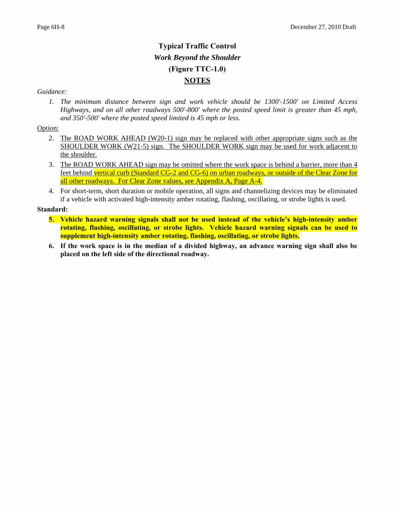


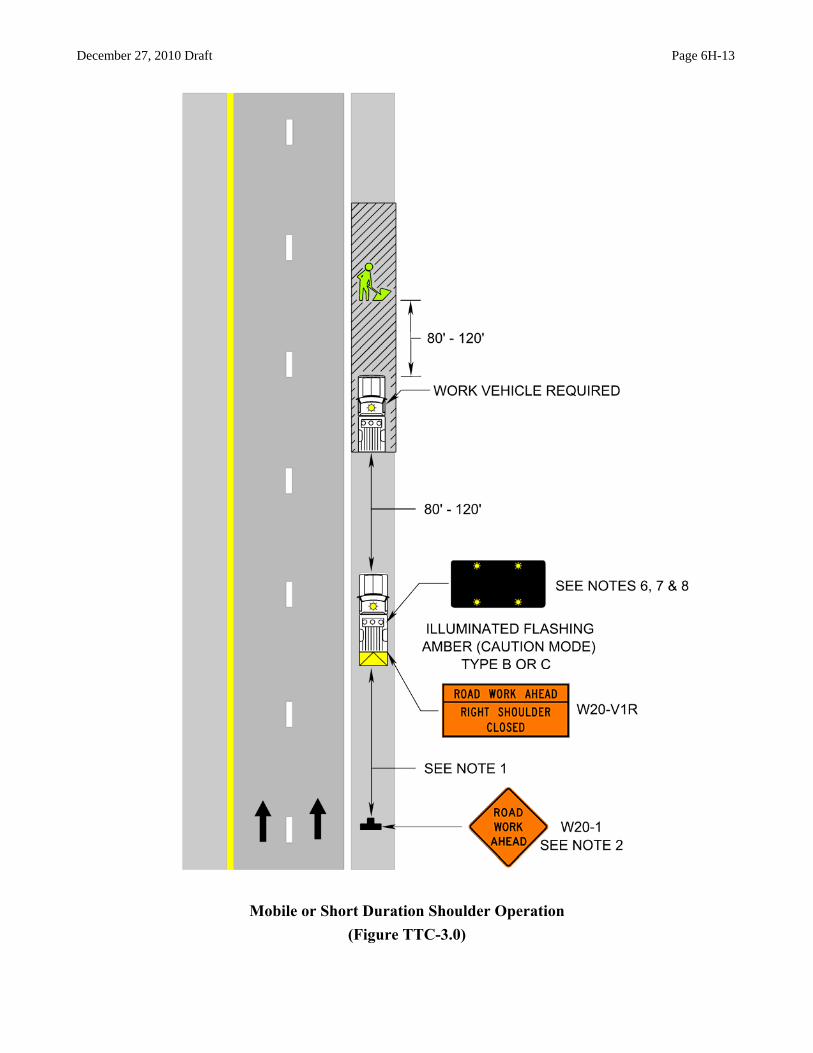

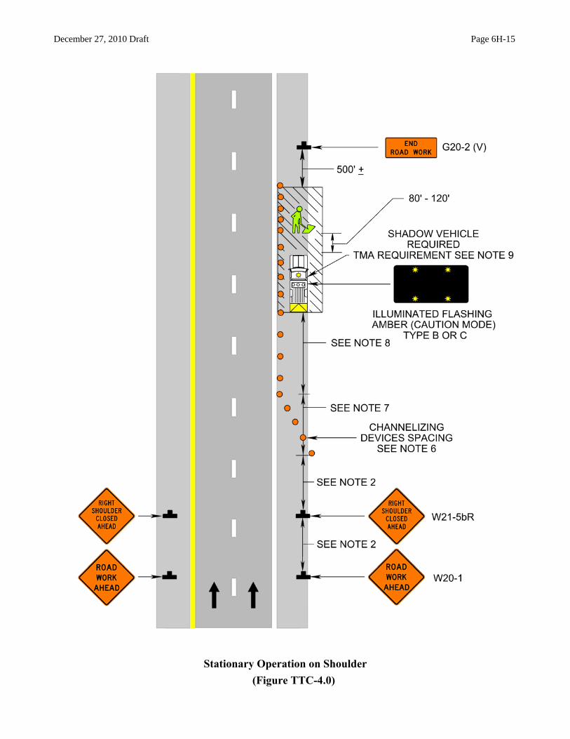
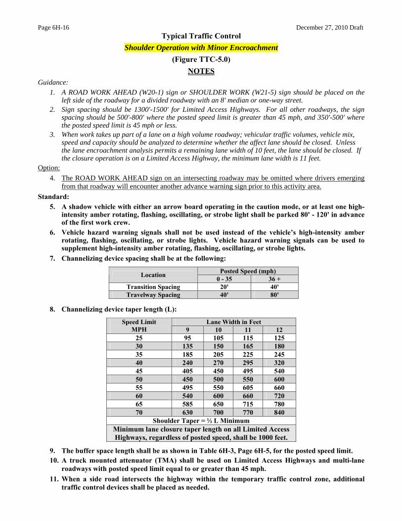


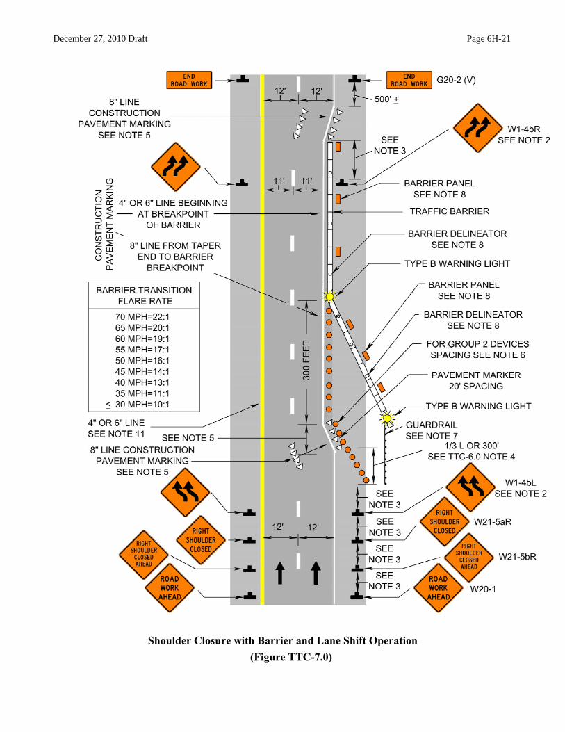


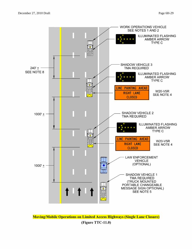


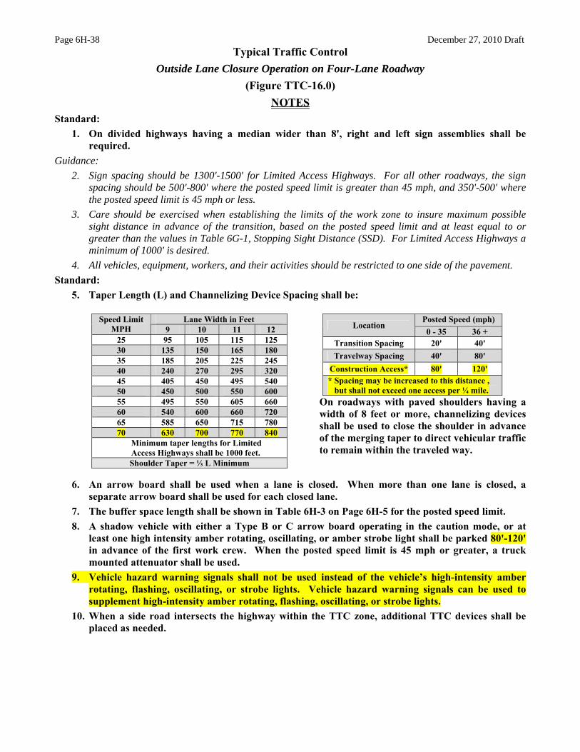


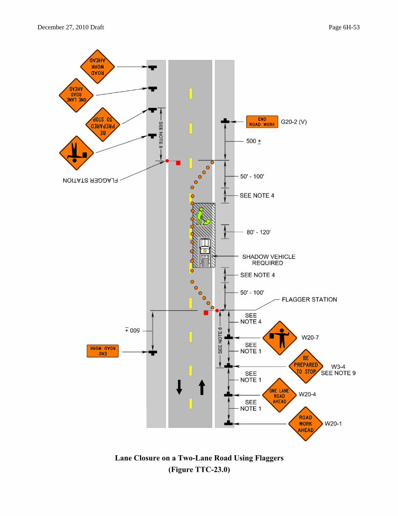

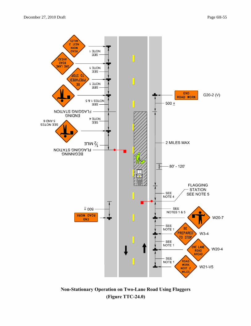


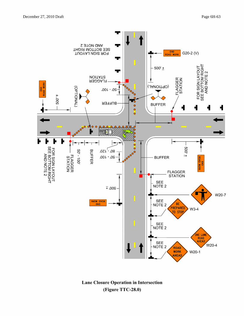

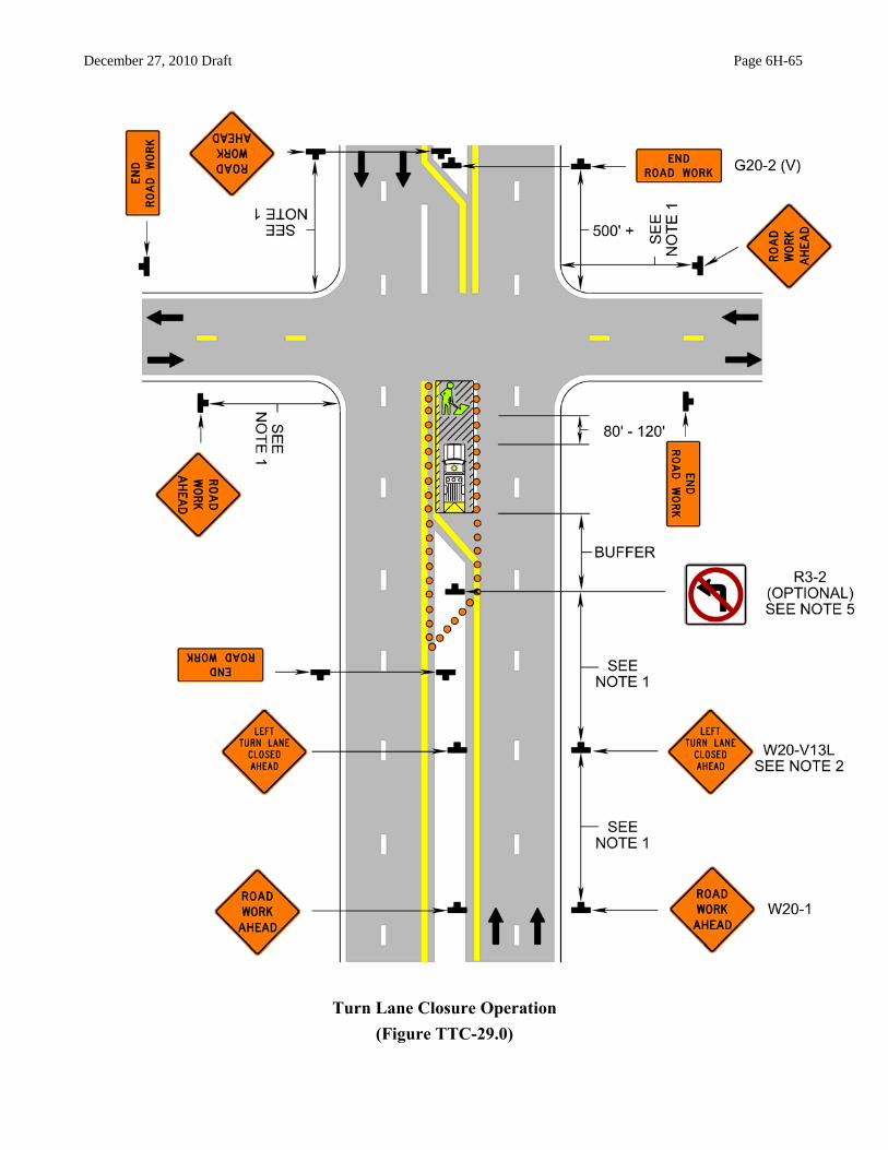


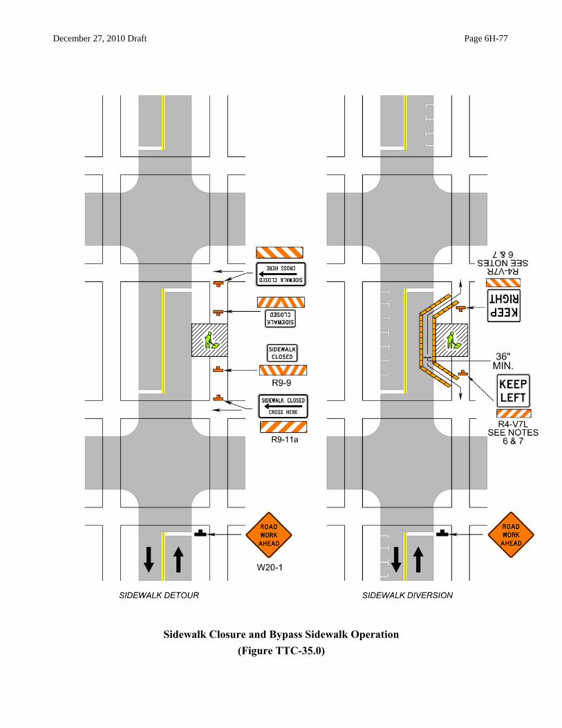


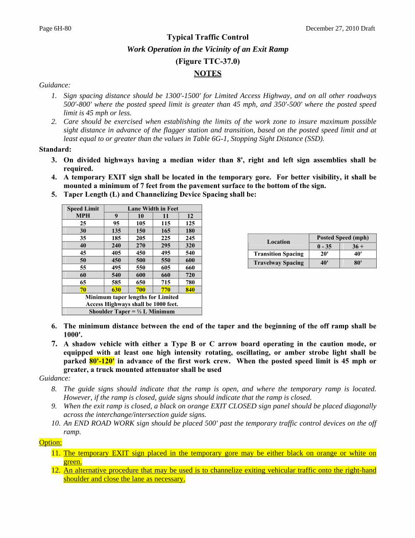


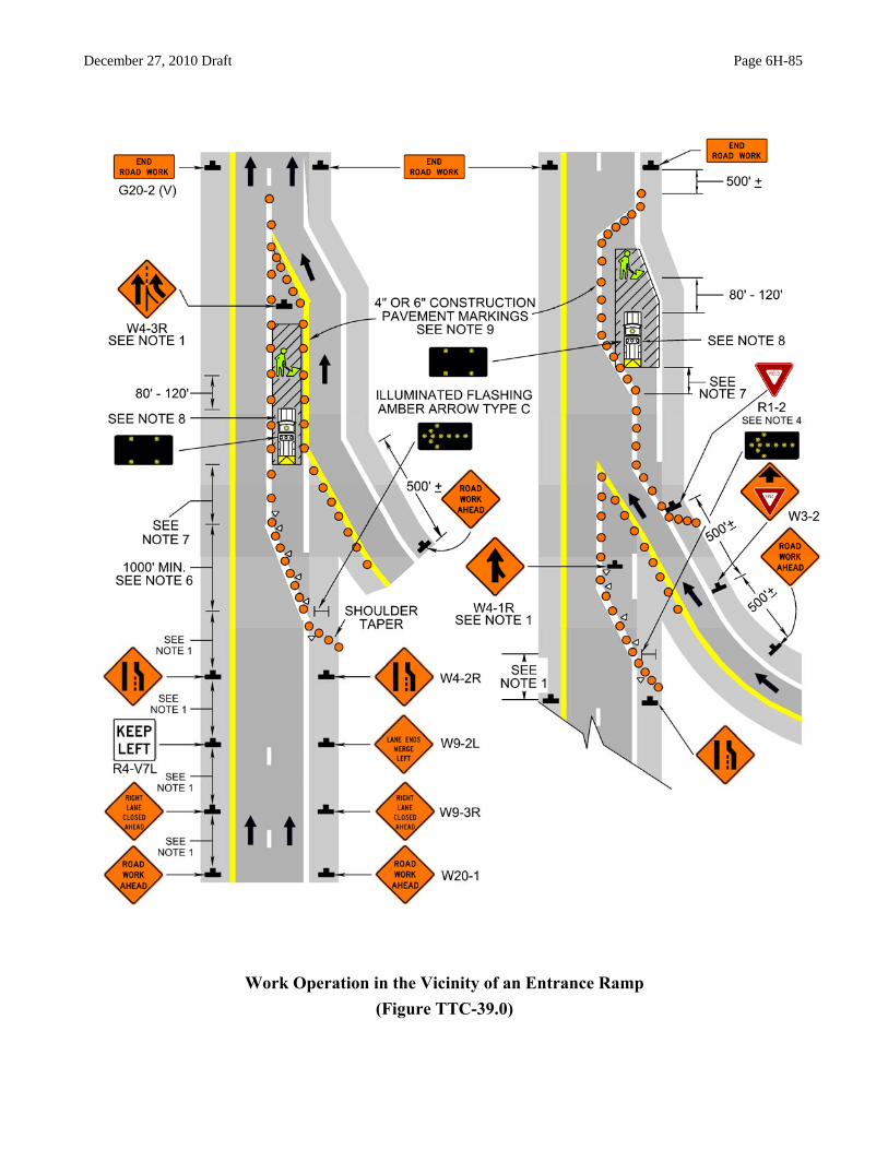


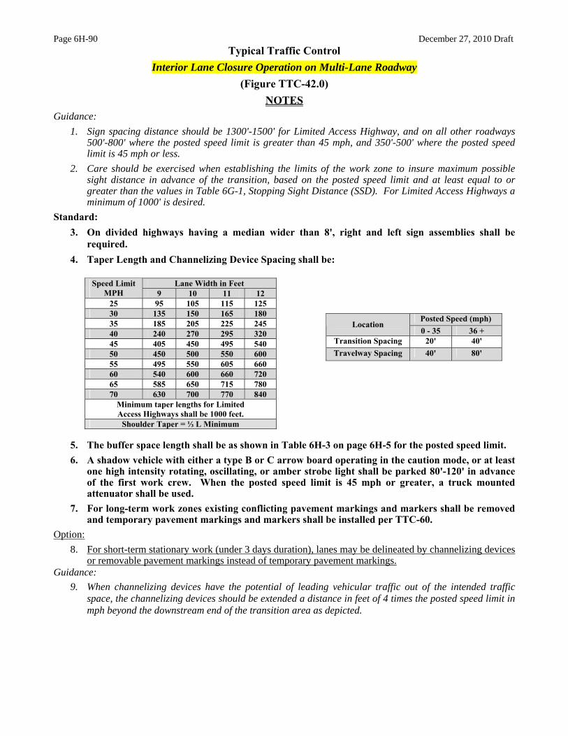


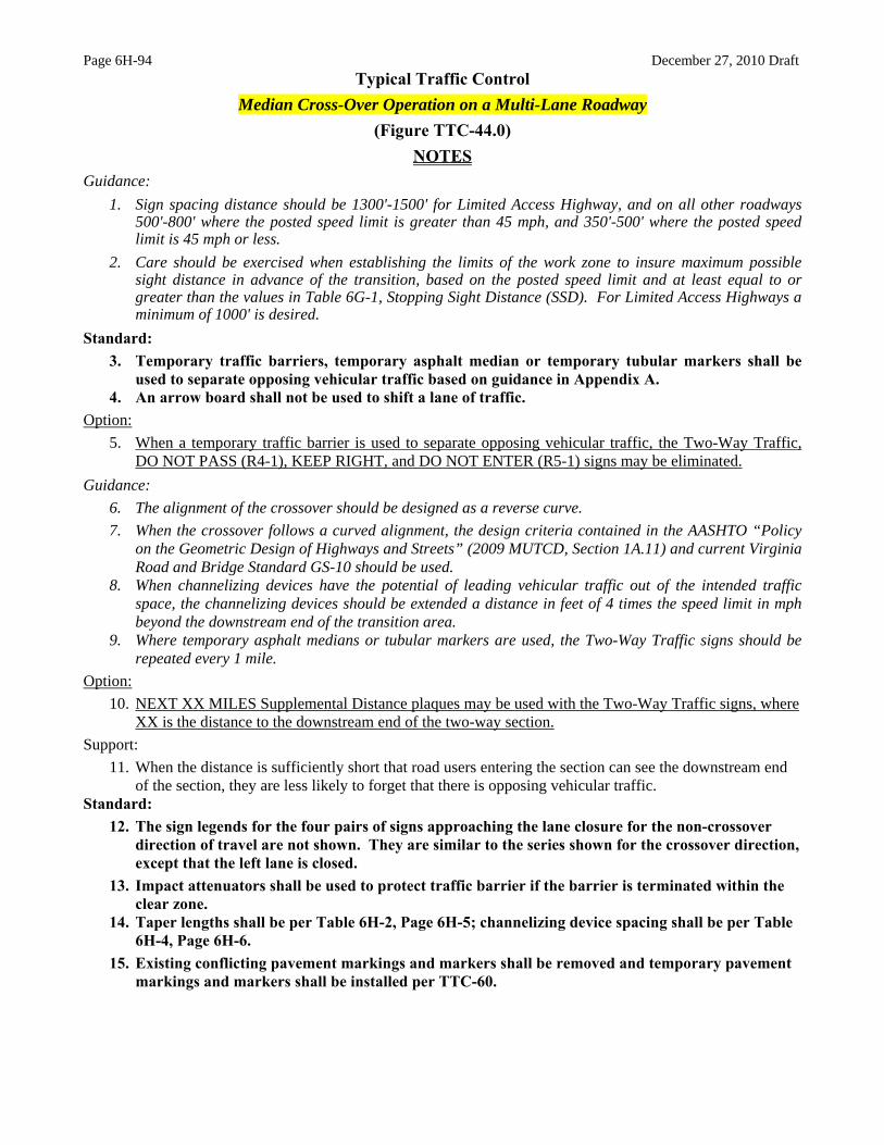


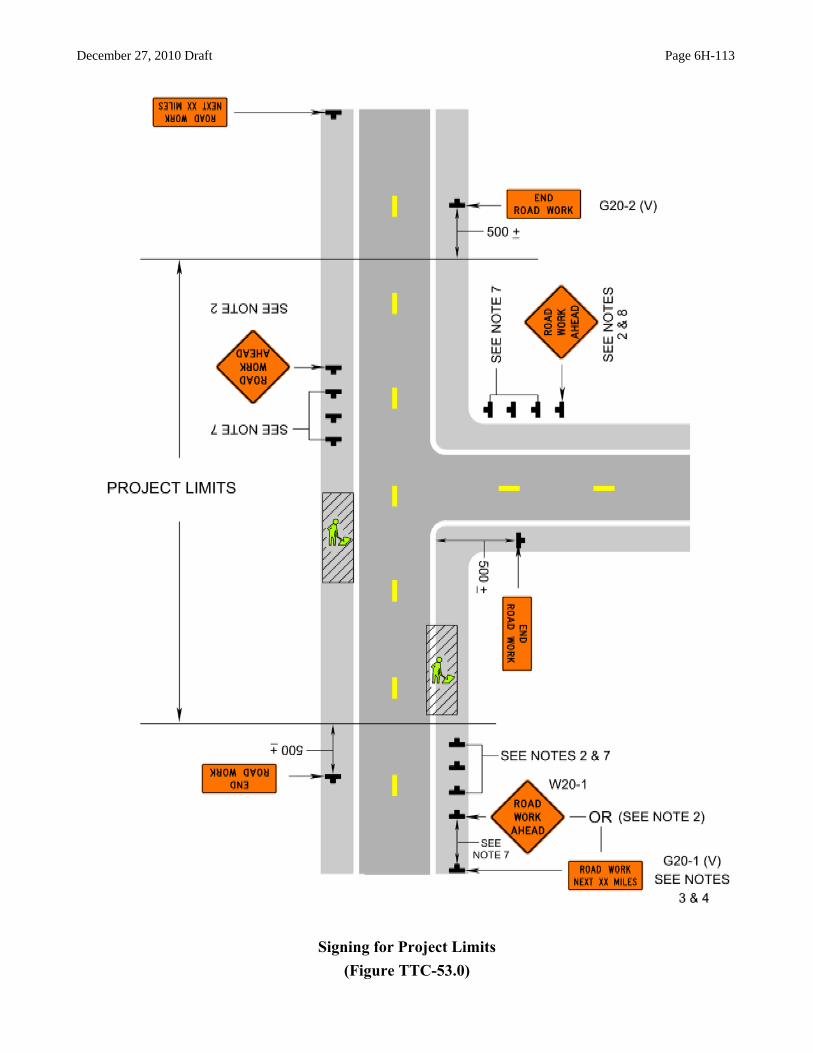


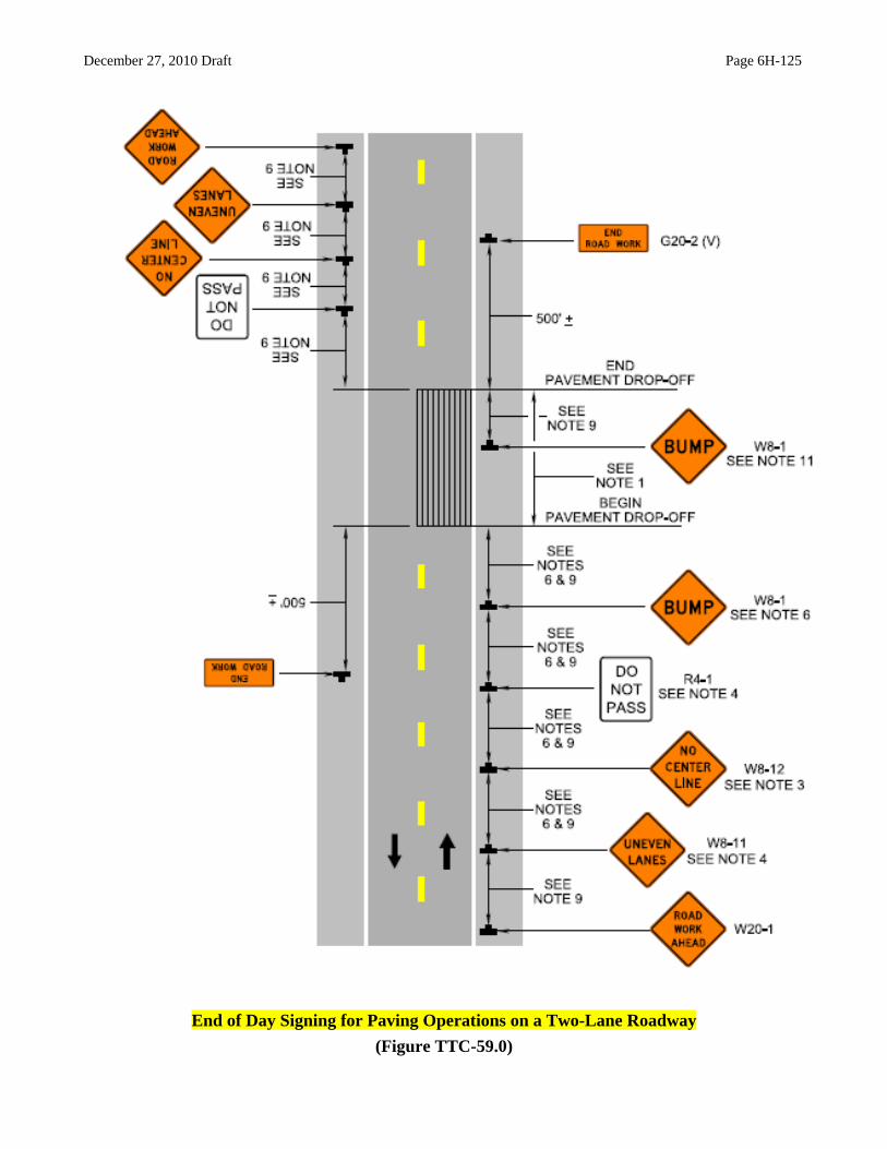
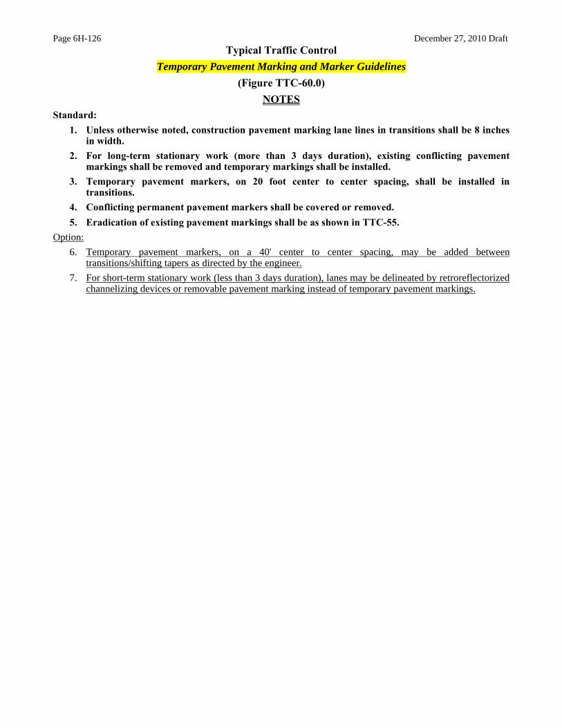


![THE DISTRIBUTION OF SPACINGS BETWEEN QUADRATIC RESIDUESkurlberg/eprints/squares1.pdf · THE DISTRIBUTION OF SPACINGS BETWEEN QUADRATIC RESIDUES 3 It is well known [15] that the spacing](https://static.documents.pub/doc/80x56/5b7b644b7f8b9adb4c8c8150/the-distribution-of-spacings-between-quadratic-residues-kurlbergeprintssquares1pdf.jpg)


