Page 1
7/15/2019 Section 7
http://slidepdf.com/reader/full/section-7-56327f9b7b4d3 1/22
H HH Hy yy yd dd dr rr ra aa au uu ul ll li ii ic cc c
G GG GM MM MK KK K I II II II I G GG GM MM MK KK K I II II II I S SS Su uu up pp pe ee er rr rs ss st tt tr rr ru uu uc cc ct tt tu uu ur rr re ee e S SS Su uu up pp pe ee er rr rs ss st tt tr rr ru uu uc cc ct tt tu uu ur rr re ee e
T R A I N I N G I N S T I T U T E
GMK 5160 S/S Hydraulics
Monoblock
M
Swing
Control
M
Counter Weight
Removal System
Swing Brake Release
Tank
M
Piston Motors
Gear Motors
Page 2
7/15/2019 Section 7
http://slidepdf.com/reader/full/section-7-56327f9b7b4d3 2/22
GMK 5160 Gear Pumps
P4
P3.2
P3.1
To Swing
Directional Valve
To Rexroth
Mono-Blk.40 Bar
To P1 & P2
GMK 5160 Hydraulic Tank
5 Bar 5 Bar
3 Bar
Optional
Coolers
To Pumps
OS55
Mono-Blk.
Drain
Mono-Blk.
Drain
Drain L ine
Page 3
7/15/2019 Section 7
http://slidepdf.com/reader/full/section-7-56327f9b7b4d3 3/22
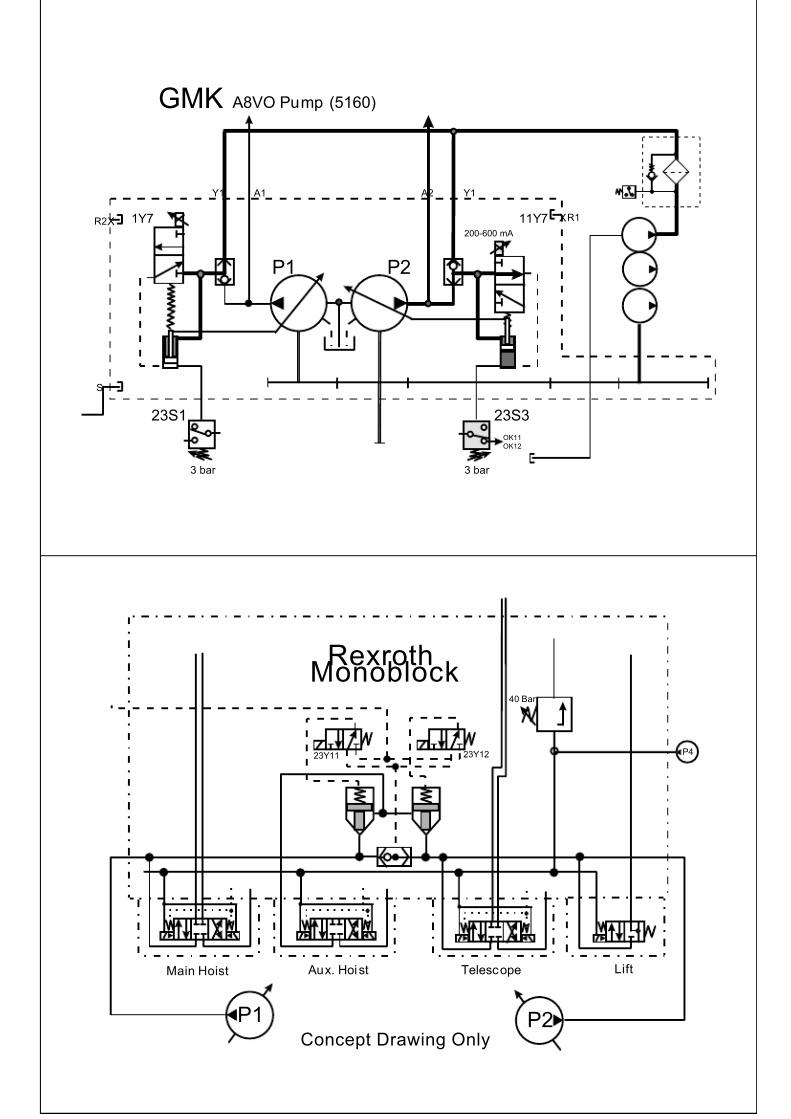
A8VO...Superstructure Pump Assembly
T R A I N I N G I N S T I T U T E
23S1
3 bar
1Y7 11Y7
Y1 A1 A2 Y1
P1 P2
XR2XR1
23S1
3 bar
S
GMK A8VO Pump (5160)
Page 4
7/15/2019 Section 7
http://slidepdf.com/reader/full/section-7-56327f9b7b4d3 4/22
23S1
3 bar
1Y7 11Y7
Y1 A1 A2 Y1
P1 P2
XR2 XR1
23S3
3 bar
S
OK11
OK12
200-600 mA
GMK A8VO Pump (5160)
P1
23Y11 23Y12
Concept Drawing Only
Main Hoist Aux. Hoist Telescope Lift
P2
40 Bar
P4
RexrothMonoblock
Page 5
7/15/2019 Section 7
http://slidepdf.com/reader/full/section-7-56327f9b7b4d3 5/22
Rexroth Mono BlockT R A I N I N G I N S T I T U T E
P1
23Y11 23Y12
Concept Drawing Only
Main Hoist Aux. Hoist Telescope Lift
P2
40 Bar
P4P4
Pump P440 Bar Pilot Pressure
P4
Page 6
7/15/2019 Section 7
http://slidepdf.com/reader/full/section-7-56327f9b7b4d3 6/22
P1
23Y11 23Y12
Concept Drawing Only
Main Hoist Aux . Hoist Telescope Lift
P2
40 Bar
P4
P1
Pump P1 Ramping Up
Main Hoist Only
P1
P1
23Y11 23Y12
Concept Drawing Only
Main Hoist Aux . Hoist Telescope Lift
P2
40 Bar
P4
P1
Pump P2 Ramping UpTele or Lift Only
P2
Page 7
7/15/2019 Section 7
http://slidepdf.com/reader/full/section-7-56327f9b7b4d3 7/22
P1
23Y11 23Y12
Concept Drawing Only
Main Hoist Aux . Hoist Telescope Lift
P2
40 Bar
P4
P1P1 P2
Pump P1 & P2 Ramping Up
Main Hoist and Tele or Li ft
P1 P2
P1
23Y11 23Y12
Concept Drawing Only
Main Hoist Aux . Hoist Telescope Lift
P2
40 Bar
P4
P1
P4P4
P1
M
Pump P1 Ramping Up
Main Hoist
M
Page 8
7/15/2019 Section 7
http://slidepdf.com/reader/full/section-7-56327f9b7b4d3 8/22
P1
23Y11 23Y12
Concept Drawing Only
Main Hoist Aux . Hoist Telescope Lift
P2
40 Bar
P4
P1
P4P4
P2
Pump P2 Ramping Up
Telescope
P1
23Y11 23Y12
Concept Drawing Only
Main Hoist Aux . Hoist Telescope Lift
P2
40 Bar
P4
P1 P2
Pump P2 Ramping Up
Lift Up (only)
P4P4
P2
Direct
to
Tank
Page 9
7/15/2019 Section 7
http://slidepdf.com/reader/full/section-7-56327f9b7b4d3 9/22
P1
23Y11 23Y12
Concept Drawing Only
Main Hoist Aux . Hoist Telescope Lift
P2
40 Bar
P4
P1
P4P4
P1
Pump P1 Ramping Up
Aux Hoist
Auxilary Hoist
M
1 2 3 4 5 6 7 8 9 10
Lift
GMK 5160 Lif t Circuit
300
Bar
6Y2
40Bar
Rexroth
Mono-Blk.
3 Bar
23S4
TANK
6Y11
PVR 2
Board
P2
Raising Boom
P4P4
1 2 3 4 5 6 7 8 9 10
0 - 4.25
Volts
Lift
Joystick
1 2 3 4 5 6 7 8 9 10
Large
Current
PVR 3Board
P2
5 Bar
Page 10
7/15/2019 Section 7
http://slidepdf.com/reader/full/section-7-56327f9b7b4d3 10/22
Lift
Joystick
1 2 3 4 5 6 7 8 9 10
1 2 3 4 5 6 7 8 9 10
Lift
GMK 5160 Lif t Circuit
300
Bar
6Y2
40
Bar
Rexroth
Mono-Blk.TANK
3 Bar
23S4
6Y11
PVR 2Board
P2
Lowering Boom
P4P4
1 2 3 4 5 6 7 8 9 10
0 - 4.25
Volts
Large
Current
PVR 3Board
5 Bar
MicroSwitch
Main HoistCircuit
320Bar
Hoist Brake
12Y3 12Y5
TANK
P4
40Bar
Rexroth
Mono-Block
1Y12 1Y11
1 2 3 4 5 6 7 8 9 10
Main
Hoist
Joystick
Hoist Down
MicroSwitch
0 - 4.25
Volts
1 2 3 4 5 6 7 8 9 1 0
Large
Current
P1
Page 11
7/15/2019 Section 7
http://slidepdf.com/reader/full/section-7-56327f9b7b4d3 11/22
Micro
Switch
Main Hoist
Circuit
320
Bar
Hoist Brake
12Y3 12Y5
TANK
P4
40Bar
Rexroth
Mono-Block
1Y12 1Y11
1 2 3 4 5 6 7 8 9 10
MainHoist
Joystick
Hoist Up
Micro
Switch
0 - 4.25Volts
1 2 3 4 5 6 7 8 9 1 0
Large
Current
P1
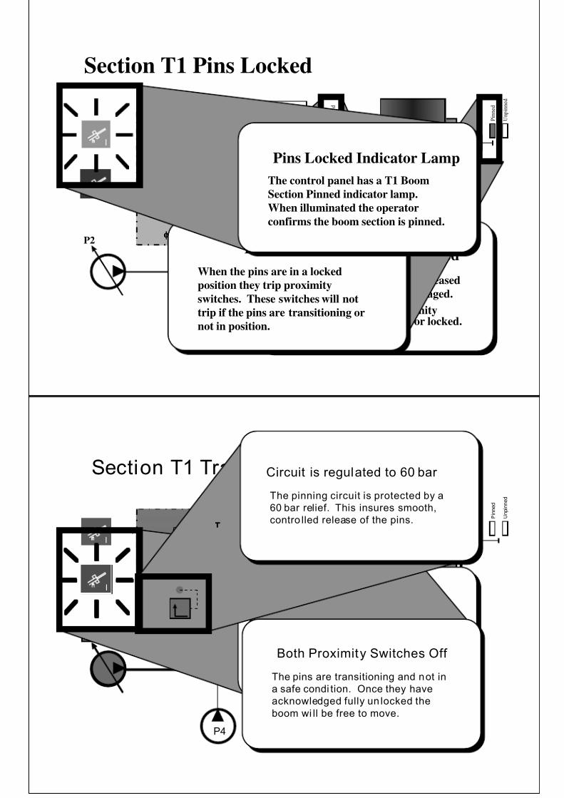
T1 Tele Section
Pin Locking
System
Page 12
7/15/2019 Section 7
http://slidepdf.com/reader/full/section-7-56327f9b7b4d3 12/22
I
Base Section
T1
Boom
Section
U n p i n n e d
Section T1 Pins Locked
P2
P4
φφφφ0.6φφφφ2
5Y10
60 bar
P i n n e d
U n p i n n e d
P i n n e d
Mechanical Spring Closed
When hydraulic pressure is released
the pins are mechanically engaged.
They will only trip the proimityswitch when fully engaged or locked.
Pins Locked
When the pins are in a locked
position they trip proximity
switches. These switches will not
trip if the pins are transitioning or
not in position.
II
Pins Locked Indicator Lamp
The control panel has a T1 Boom
Section Pinned indicator lamp.
When illuminated the operator
confirms the boom section is pinned.
I
I
Base Section
T1
Boom
Section
U n p i n n e d
Section T1 Transitioning
P2
P4
f0.6f2
5Y10
60 bar
P i n n e d
U n p i n n e d
P i n n e d
P2
Base Section
T1
Boom
Section
P i n n e d
P i n n e d
I
IIIIIIII
Pins Moving; Lamp Flashing
The control panel has a T1 Boom
Section Unlocked indicator lamp.
When flashing the operator confirms
the pins are moving.Both Proximity Switches Off
The pins are transitioning and not in
a safe condi tion. Once they have
acknowledged fully un locked the
boom wi ll be free to move.
Circuit is regulated to 60 bar
The pinning circuit is protected by a
60 bar relief. This insures smooth,
contro lled release of the pins.
Page 13
7/15/2019 Section 7
http://slidepdf.com/reader/full/section-7-56327f9b7b4d3 13/22
I
P i n n e d
P i n n e d
Base Section
T1
Boom
Section
Section T1 Pins Unlocked
IIIIII
Base Section
T1
Boom
Section
U n p i n n e d
P2
P4
f0.6f2
5Y10
60 bar
U n p i n n e d
P2
U n p i n n e d
U n p i n n e d
I
I
Pins Unlocked; Lamp On
The control panel has a T1 Boom
Section Unlocked indicator lamp.
When on solid the operator conf irms
the pins have moved and are
completely unlocked. The boom is
now ready to move.
Unpinned Proximity Switches On
The pins are unlocked and are ready to
allow the boom to move.
Staged Monton
Telescope Cylinder
System
Page 14
7/15/2019 Section 7
http://slidepdf.com/reader/full/section-7-56327f9b7b4d3 14/22
Staged
Monton Cylinder
System
5Y13
5Y12
GMK5160
P2
5Y11
Hydraulic Directional Valve
This valve is the directional control valve
mounted on the Mono-Block which controls
direction of the telescope circuit . Pump P2 is
shown here which is the primary pump. High
speed can be engaged by pressing the floor
switch which adds pump P1 .
Cylinder #1
This cylinder is a two stage
cylinder that acts similar to the
domestic Grove “ Trombone”
Cylinder.
It also has transfer tube that
runs through cylinder #1 to
feed cylinder #2
Cylinder #2
This cylinder is a single stage
cylinder that entends section T3
Section T4 is cable extended
sychronized to the T3 section
Holding ValvesThese valves directly hold the
cylinder oil while extended. Both are
pilot operated and shifted when a
cylinder is to be retracted.
Logic Valve
This logic or poppet valve directs
oil to cylinder #2 which controls
section T3 & T4. This opens or
closes based on oil control on
topside of cylinder.
Logic Cartridge Valve
This logic or poppet cartridge valve
directs oil to the different stages of
cylinder #1 which controls boom
sections T1 & T2. This valve opens or
closes the different passages based on
oil from the 3 solenoid control valves.
Logic Control Valves
These valves directly hold the
cylinder oil while extended. Both are
pilot operated and shifted when a
cylinder is to be retracted.
Shuttle Valve
Al lows the highest pressure to the
back side of the cartridge valve and
permits smooth opening and closing.
Section T1Extending
Cylinder #1
5Y13
5Y12
P2
Power 5Y32
5Y11
P2
T1
Page 15
7/15/2019 Section 7
http://slidepdf.com/reader/full/section-7-56327f9b7b4d3 15/22
Section T2
Extending
Cylinder #1
5Y13
5Y12
P2
Power 5Y32
5Y11
P2
Power 5Y11
T2
Section T3 & T4Extending
Cylinder #2
5Y13
5Y12
P2
Power 5Y32
5Y11
P2
Power 5Y12 & 5Y13
T3
&
T4
Page 16
7/15/2019 Section 7
http://slidepdf.com/reader/full/section-7-56327f9b7b4d3 16/22
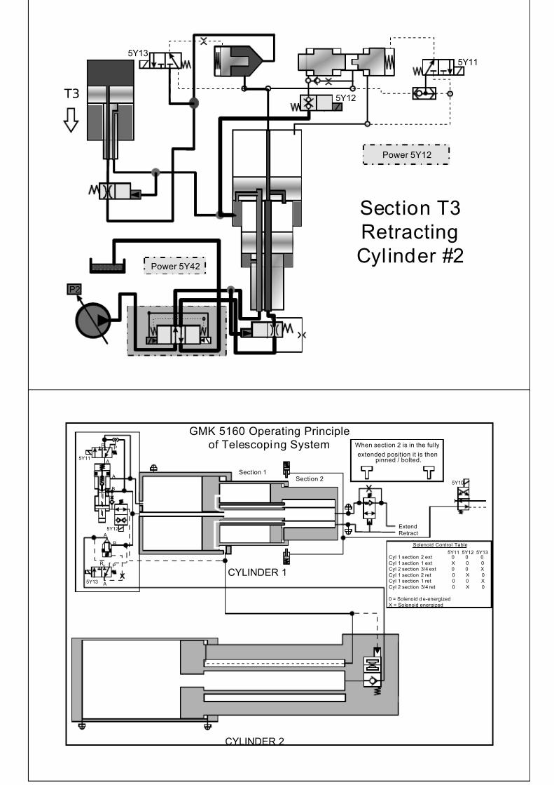
Section T1
Retracting
Cylinder #1
5Y13
5Y12
P2
Power 5Y42
5Y11
Power 5Y12
P2
T1
Section T2Retracting
Cylinder #1
5Y13
5Y12
P2
Power 5Y42
5Y11
Power 5Y13
P2
T2
Page 17
7/15/2019 Section 7
http://slidepdf.com/reader/full/section-7-56327f9b7b4d3 17/22
Section T3
Retracting
Cylinder #2
5Y13
5Y12
P2
Power 5Y42
5Y11
Power 5Y12
P2
T3
GMK 5160 Operating Principle
of Telescoping System5Y11
5Y13
5Y12
A
B
A
R P
A
RP
Section 1Section 2
CYLINDER 1
A
B
When section 2 is in the fully
extended position it is thenpinned / bolted.
Extend
Retract
Solenoid Control Table
Cyl 1 section 2 ext 0 0 0
Cyl 1 section 1 ext X 0 0
Cyl 2 section 3/4 ext 0 0 X
Cyl 1 section 2 ret 0 X 0
Cyl 1 section 1 ret 0 0 X
Cyl 2 section 3/4 ret 0 X 0
0 = Solenoid d e-energized
X = Solenoid energized
5Y11 5Y12 5Y13
CYLINDER 2
5Y10
Page 18
7/15/2019 Section 7
http://slidepdf.com/reader/full/section-7-56327f9b7b4d3 18/22
Swing System
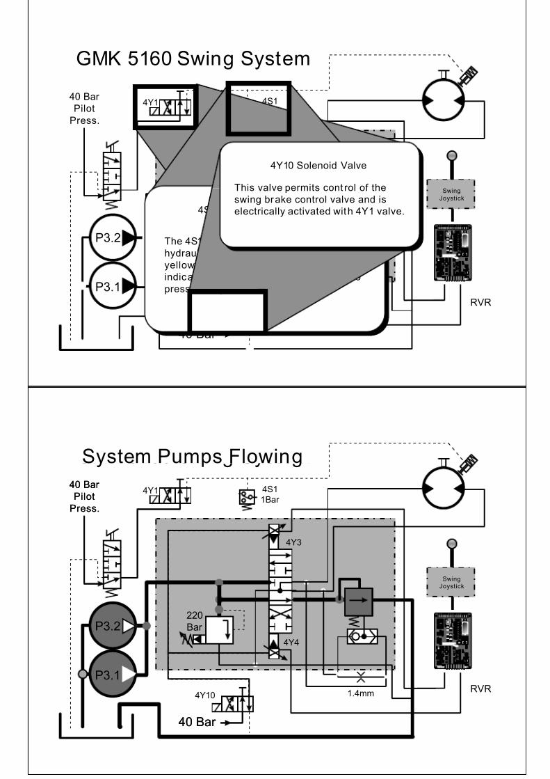
GMK 5160 Swing System
40 Bar
Pilot
Press.
4Y1
275
Bar
4S1
1Bar
4Y3
4Y4
1.4mm4Y10
40 Bar
Swing
Joystick
P3.2
P3.1
Swing Brake Pedal
This brake contro l is primarily
used as a holding brake. It is
proportionally controlled.
4Y10
Swing Control Valve
This assembly/enclosure controls
the hydraulic oil flow to the swing circuit.
RVR
Dual Gear Pumps
These gear pumps P3.1 and P3.2
are driven through the same shaft.
Two pumps are provided to createthe needed volume.
RVR Amp Board
This board con trols the Min, Maxand Ramping Functions of the
Swing circuit. Time delays
prevents back checking and shock
loading.
40 Bar Pilot Pressure
The 40 bar pilot pressure is created
by gear pump P4.
In this diagram P4 is not shown
Single Swing Motor
Older Generation GMK’s have
single large capacity swing motors.
New Generation GMK’s have
smaller multiple motor systems
Joy Stick Control
The Joy Stick Control sends s ignal
directly to the RVR board. The
RVR then controls the swing
components .
Page 19
7/15/2019 Section 7
http://slidepdf.com/reader/full/section-7-56327f9b7b4d3 19/22
4Y10
GMK 5160 Swing System
40 Bar
Pilot
Press.
4Y1
220
Bar
4S1
1Bar
4Y3
4Y4
1.4mm
40 Bar
Swing
Joystick
P3.2
P3.1
4Y1 Solenoid Valve
This valve permits release of the
swing brake and is electrically
activated with 4Y10 valve.4S1 Brake Release Indicator
The 4S1 Switch is activated when the
hydraulic line sees a 1 bar signal. The
yellow indicator light in the cab goes out
indicating the brake is released. When no
pressure is present, the light is on.
4Y10 Solenoid Valve
This valve permits cont rol of the
swing brake control valve and is
electrically activated with 4Y1 valve.
RVR
GMK 5160 Swing System
40 Bar
Pilot
Press.
4Y1
220
Bar
4S1
1Bar
4Y3
4Y4
1.4mm
40 Bar
P3.2
P3.1
Swing
Joystick
System Pumps Flowing
P3.2
P3.1
40 Bar
Pilot
Press.
40 Bar
4Y10RVR
Page 20
7/15/2019 Section 7
http://slidepdf.com/reader/full/section-7-56327f9b7b4d3 20/22
220
Bar
4S1
1Bar
4Y3
4Y4
1.4mm
4Y1
P3.2
P3.1
Swing
Joystick
Releasing the Brake
P3.2
P3.1
40 Bar
Pilot
Press.
40 Bar
4Y10RVR
220
Bar
4S1
1Bar
4Y3
4Y4
1.4mm
4Y1
P3.2
P3.1
Swing
Joystick
Swing Left
P3.2
P3.1
40 Bar
Pilot
Press.
40 Bar
4Y10
6.3 - .75 Volt s
0- 750 ma
Current
RVR
Page 21
7/15/2019 Section 7
http://slidepdf.com/reader/full/section-7-56327f9b7b4d3 21/22
220
Bar
4S1
1Bar
4Y3
4Y4
1.4mm
4Y1
P3.2
P3.1
Swing
Joystick
Swing Left
P3.2
P3.1
40 Bar
Pilot
Press.
40 Bar
4Y10
6.3 - .75 Volt s
0- 750 ma
Current
RVR
220
Bar
4S1
1Bar
4Y3
4Y4
1.4mm
4Y1
P3.2
P3.1
Swing
Joystick
Swing Right
P3.2
P3.1
40 Bar
Pilot
Press.
40 Bar
4Y10
6.3 - 12.6 Volt s
0- 750 ma
Current
RVR
Page 22
7/15/2019 Section 7
http://slidepdf.com/reader/full/section-7-56327f9b7b4d3 22/22
220
Bar
4S1
1Bar
4Y3
4Y4
1.4mm
4Y1
P3.2
P3.1
Swing
Joystick
Swing Right
P3.2
P3.1
40 Bar
Pilot
Press.
40 Bar
4Y10
6.3 - 12.6 Volt s
0- 750 ma
Current
RVR
220
Bar
4S1
1Bar
4Y3
4Y4
1.4mm
4Y1
P3.2
P3.1
Swing
Joystick
Applying the Brake
P3.2
P3.1
40 Bar
Pilot
Press.
40 Bar
4Y10
6.3 - 12.6 Volt s
0- 750 ma
RVR
Foot
Pressure