150865 7-1 Section 7 Programming: Step-by-Step Complete Reference The Model 5230 Remote Annunciator is for programming the 5207 panel. You must be in Step Programming Mode (also known as mode 27) to program the panel. See the following sections for details. 7.1 Using Step Programming Enter Step Programming mode Press , followed by the code that has been programmed as code 0 (the factory programmed value for code 0 is 123456). If you have entered mode 27 correctly, the display will show 1 PWR UP CLR (Step 1, Power-up Clear). Press to make selections for this step. Press again to move to the next step. Note: If you receive a trouble beep and the message TRY AGAIN appears, either you are not using the correct code 0, or the EEPROM could be malfunctioning. If the problem is the EEPROM, you must obtain a new default EEPROM from Silent Knight. Exit Step Programming Press . You will return to normal operation. Moving through the Steps and Sub-Steps To move sequentially through the options: Press until you reach the step (option) you want to program. To go directly to step: If you know the step you want to go to, you can save time by moving directly to the step. Press . Enter the desired step number, then press . The new step will be displayed. To go to directly a sub-step: Some steps contain sub-steps (see the diagram on the next page for an example). To go to a particular sub-step, first go to the step. Then, press followed by the substep number and press . For example, to go to step 14.2, you would press the following sequence of keys: chart continued on next page 2 7 ENTER ENTER ENTER STEP STEP CLEAR CLEAR ENTER STEP STEP ENTER STEP ENTER STEP STEP 1 4 ENTER STEP 2
The Model 5230 Remote Annunciator is for programming the 5207 panel. You must be in Step Programming Mode (also known as mode 27) to program the panel. See the following sections for details.
7.1 Using Step Programming
Enter Step Programming mode
Press , followed by the code that has been programmed as code 0 (the factory programmed value for code 0 is 123456). If you have entered mode 27 correctly, the display will show 1 PWR UP CLR (Step 1, Power-up Clear). Press
to make selections for this step. Press again to move to the next step.Note: If you receive a trouble beep and the message TRY AGAIN appears, either you are not using the correct code 0, or the EEPROM could be malfunctioning. If the problem is the EEPROM, you must obtain a new default EEPROM from Silent Knight.
Exit Step Programming Press . You will return to normal operation.
Moving through the Steps and Sub-Steps
To move sequentially through the options:
Press until you reach the step (option) you want to program.
To go directly to step:If you know the step you want to go to, you can save time by moving directly to
the step. Press . Enter the desired step number, then press . The new step will be displayed.
To go to directly a sub-step:Some steps contain sub-steps (see the diagram on the next page for an example).
To go to a particular sub-step, first go to the step. Then, press followed by
the substep number and press . For example, to go to step 14.2, you would
press the following sequence of keys:
chart continued on next page
2 7 ENTER
ENTER ENTER
STEP STEP CLEAR CLEAR
ENTER
STEP STEP ENTER
STEP
ENTER
STEP STEP 1 4 ENTER STEP 2
Model 5207 Fire Control/Communicator Installation and Operation Manual
7-2 150865
Selecting Options ScrollingFor most options, you enter numbers in the same way as if you were using a calculator. The digits appear on the right side of the display and scroll to the left as you continue to enter data.
TogglingIn some steps, pressing a key will cause the corresponding digit to appear and disappear on the display. When a digit appears, it indicates that the option is selected. A dash indicates that the option is not selected. In the following example, options 1, 5, and 7 are selected:
Entering numbers greater than 9
Use the key as shown below to enter numbers 10-15. Hexadecimal digits (in parentheses) appear on the screen to represent these numbers.
Programming ExamplesThe following examples demonstrate how to use Step Programming. The selections you make in each installation will vary depending on each customer’s needs. The way you move through Mode 27 may also vary from how it is described here.
Example 1: Programming Location Description Names
Suppose you want to program the Model 5230 Annunciator to display meaningful location names for Zones 3 and 5. The words you wish to display are GARAGE for Zone 3 and EAST OFFICE for Zone 5. These words are part of the 5230 library of names and can be selected using Step Programming. See Table 2-2 for a complete list of words contained in the library.
One-Word Display
1. From the 1 PWR UP CLR display, press to go to Step 26.1.
2. Press until you reach Zone 3. The first line of the LCD will
read .
3. Press as many times as necessary until the word GARAGE is dis-
played on the LCD. Press to select.
Two-Word DisplayTo program Zone 5 to display EAST OFFICE, you will have an additional step since you are programming two words instead of one.1. If necessary, enter Step Programming mode from the Date/Time dis-
play by pressing , then enter your access code.
2. From the 1 PWR UP CLR display, press to go to Step
26.1. (If you are already in Step 26, just press , then the num-
ber of the zone you want to change and press .)
3. Press until you reach Zone 5. The first line of the LCD will
read .
4. Press as many times as necessary until the word EAST is dis-played on the LCD.
5. To add the second word, press until you reach OFFICE. Press
to select.
Example 2: Adding a New Access Code
1. If necessary, enter Step Programming mode from the Date/Time dis-
play by pressing , then enter your access code.
2. From the 1 PWR UP CLR display, press .
3. Press .
4. Press the number of the code you want to add or change. Press
.
5. Enter the new access code number. Press .
2 6 ENTER
ENTER
26.3
1
ENTER
2 7 ENTER
2 6 ENTER
STEP
ENTER
ENTER
26.5
1
2
2 7 ENTER
2 7 ENTER
2 2 ENTER
STEP
ENTER
ENTER
Model 5207 Fire Control/Communicator Installation and Operation Manual
7-4 150865
7.2 Step Programming Options
This section is organized in step order and provides complete instructions for each step.
Step 1. Power Up Clear
Step 2. Device Enables
Display Description
The two digits of this step are used to program two options, BELL TEST AT RESTORE (digit 1) and DEFAULT MODE (power up) REPORTING (digit 2).
Digit 1:
0 = No bell test at restore.8 = Bell test will occur at restore.
Digit 2:
0 = A report will not be sent if the system enters power up mode.1 = An "open" report will be sent if the system enters power up mode.
Example 1: If you select "80" for this step, a bell test will occur at restore (dig-it 1) and no report will occur if the system enters power up mode (digit 2).
Example 2: If you select "01" for this step, a bell test will not occur at restore (digit 1) and the system will report "Open" if it enters power up mode (digit 2).
Display Description
Step 2 allows you to enable the dialer, printer, and 24-volt smoke power.
0 = Dialer. The dialer must be enabled. Do not change the factory program-ming.
1 = Printer. Enable the printer if your installation includes a 5260 printer in-terface. (The 5260 is not UL listed for use with the 5207.)
7 = 24-V System. Enables 24V power. Do NOT disable.
2 - 6 = Unused. These digits are reserved by the manufacturer for future use. Leave these blank at all times.
Programming: Step-by-Step Complete Reference
150865 7-5
Step 3. More System Options
Step 4. Display Rate
Display Description
Step 3 allows you to select seven system options shown below. To select an option, press its number.
0 = Cadenced pulsing of bells. If you select this option, bells will pulse in the pattern shown below (for customizing patterns, refer to Steps 27 and 28):
3.5 seconds on, .5 seconds off3.5 seconds on, .5 seconds off3.5 seconds on, 4.5 seconds off
1 = Code required at the panel. If you select this option, users will have to enter a code to perform tasks on the built-in touchpad.
2 = Trouble alert tone used for pre-alarm sound. If you choose this option the built-in trouble alert will sound when a trouble condition occurs.
3 = Pulsing fire bells. Select this option if you want fire alarm bells to pulse one second on, one second off. (If you want fire bells to have cadenced pulsing instead of one second on, one second off pulsing, choose both this option AND cadenced pulsing.)
4 = Trouble alert tone will sound during smoke delays. If you choose this option, the built-in trouble alert sounder will sound when a trouble condition occurs.
5 = Report fast restores. This option causes restores that occur as soon as the alarm situation is corrected instead of waiting for the shutdown time.
6 = Must be enabled. Do NOT de-select.
7 = Time displays in military format. If you select this option, the system time will display in the 24-hour military format instead of the 12-hour with AM/PM format.
Display Description
The two digits of this step are used to program two options that have to do with the Model 5230 Remote Annunciator.
Digit 1 = The rate that the 5230 LCD displays text, that is, how long a display stays on the LCD. The choices are:
0 = 0.5 sec1 = 1 sec2 = 1.5 sec3 = 3 sec
Digit 2 = Maximum number of supervised annunciators. Enter 0-7. "0" means no annunciators will be supervised.
Example:Entering "14" for this step indicates that all annunciators will display text for 1 second (Digit 1) and your installation has 4 (1-4) annunciators (Digit 2).
Model 5207 Fire Control/Communicator Installation and Operation Manual
7-6 150865
Step 5. Miscellaneous Options
Step 6. Internal Zone Options
Display Description
Step 5 is for programming several system options, including bell supervision.
0 = Walk tests will be reported. Select this option if you want walk tests reported to the central station.
1 = A feature that makes the system clock more accurate. Do NOT de-select.
2 = Ground fault detection enabled. This is required. Do NOT de-select.
3 = Sequential bell test. Enabling this option means that when a dialer test or power-up occurs, the four bells will ring sequentially (first bell 1, then bell 2 and so on), instead of all four at the same time.
4 = Bell 1 is supervised. This option must be enabled if bell 1 is used.
5 = Bell 2 is supervised. This option must be enabled if bell 2 is used.
6 = Bell 3 is supervised. This option must be enabled if bell 3 is used.
7 = Bell 4 is supervised. This option must be enabled if bell 4 is used.
Display Description
Step 6 is for programming various options for zones 1-8. To select an option for a zone, go to the appropriate substep and enter the zone number. (Options for expansion zones 9-16 are programmed in Step 7.)
Example:
Suppose you want zones 2 and 3 to be pre-alarm delayed. Pre-alarm delays are programmed at Step 6.8. Press "23" at Step 6.8.
24 Hour alarmZones will be active 24 hours. Must be selected for all zones. Do NOT change the factory programming for this step.
Trouble SupervisedSelect zones that will be supervised for trouble (typi-cally this is all zones).
Option not used. Do NOT select anything.
Programming: Step-by-Step Complete Reference
150865 7-7
Programming Zone Response Time (Steps 6.5 & 6.6)
There are four possible response times. To program the response times, select the zone number that should have that response time in Steps 6.5 and 6.6, as follows:
Normally Open zonesZones will be Normally Open. Must be selected for all zones. Do NOT change the factory programming for this step (NFPA re-quires that all fire zones be programmed as N.O. supervised).
Steps 6.5 and 6.6 are for programming zone response time. For more information see “Programming Zone Response Time”, especially if you have never programmed loop response times with the 5207.
Use this step to select the 3-to-4 second or 30-to-40 second response times for zones 1-8. Select the zone numbers of the zones that should have either of these speeds. For the 30-to-40 second speed, you will have to enter the zone numbers again in Step 6.6. Note that the default for all zones is 3 to 4 seconds. You will need to de-select any zones that should not have the 3-to-4 or 30-to-40 response times by pressing the zone number so that it is not displayed on the LCD. See Table 6-1.
Use this step to select the 15-to-20 second or 30-to-40 second response times for zones 1 to 8. Select the numbers of the zones that should have either of these speeds. For the 30-40 second speed, you should also have entered the zone numbers in Step 6.5. Be sure to de-select any zones that should not be displayed in this step. See Table 6-1.
Table 6-1 Steps 6.5 and 6.6 Programming
Desired Speed for Zone
Step 6.5 Step 6.6 Explanation
0.094 - 0.25 seconds Do not select zone number.
Do not select zone number.
Leave the zone number blank in both steps for any zones that should have this response time.
Note: This very fast response time can increase the possibility of false alarms, since transients and other interference can set off alarm conditions in such a short time span. Silent Knight recommends that you do not use this response time unless you have to (because, for example, the installation you are protecting requires this quick a response time even if false alarms could result).
3 to 5 seconds Select zone num-ber.
Do not select zone number.
In Step 6.5 only, select the zone number of zones 1-8 that should have this response time.
15 to 20 seconds Do not select zone number.
Select zone num-ber.
In Step 6.6 only, select the zone number of zones 1-8 that should have this response time.
30 to 40 seconds Select zone number.
Select zone num-ber.
In both Steps 6.5 and 6.6, select the zone number of zones 1-8 that should have this response time.
Display Description
Model 5207 Fire Control/Communicator Installation and Operation Manual
7-8 150865
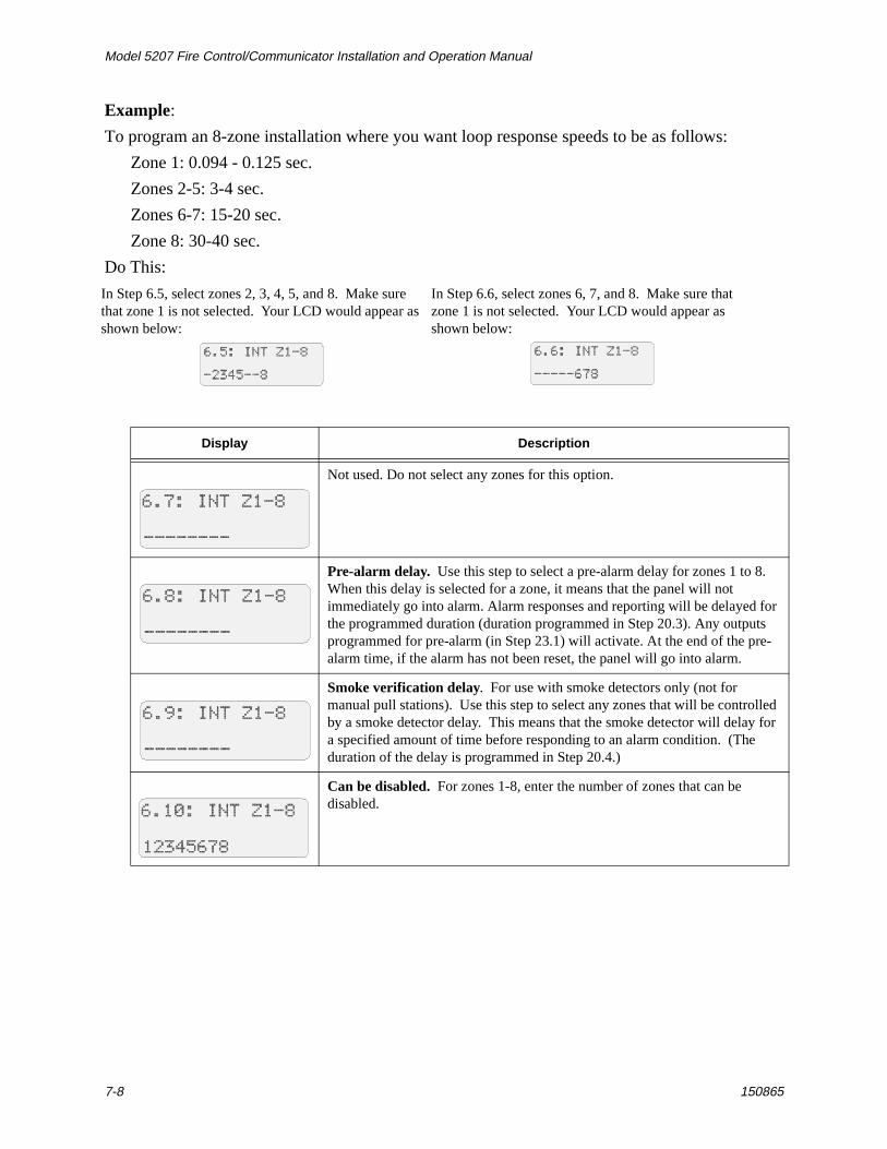
Example:
To program an 8-zone installation where you want loop response speeds to be as follows:
Zone 1: 0.094 - 0.125 sec.
Zones 2-5: 3-4 sec.
Zones 6-7: 15-20 sec.
Zone 8: 30-40 sec.
Do This:
In Step 6.5, select zones 2, 3, 4, 5, and 8. Make sure that zone 1 is not selected. Your LCD would appear as shown below:
In Step 6.6, select zones 6, 7, and 8. Make sure that zone 1 is not selected. Your LCD would appear as shown below:
Display Description
Not used. Do not select any zones for this option.
Pre-alarm delay. Use this step to select a pre-alarm delay for zones 1 to 8. When this delay is selected for a zone, it means that the panel will not immediately go into alarm. Alarm responses and reporting will be delayed for the programmed duration (duration programmed in Step 20.3). Any outputs programmed for pre-alarm (in Step 23.1) will activate. At the end of the pre-alarm time, if the alarm has not been reset, the panel will go into alarm.
Smoke verification delay. For use with smoke detectors only (not for manual pull stations). Use this step to select any zones that will be controlled by a smoke detector delay. This means that the smoke detector will delay for a specified amount of time before responding to an alarm condition. (The duration of the delay is programmed in Step 20.4.)
Can be disabled. For zones 1-8, enter the number of zones that can be disabled.
Programming: Step-by-Step Complete Reference
150865 7-9
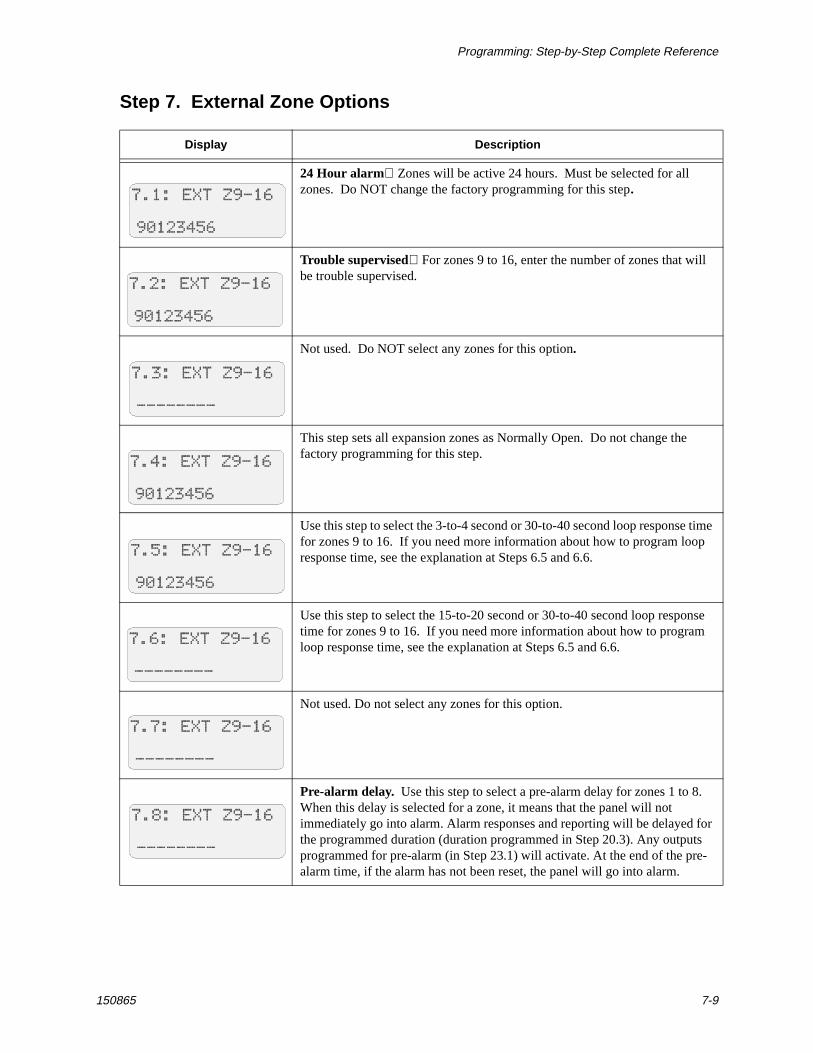
Step 7. External Zone Options
Display Description
24 Hour alarmZones will be active 24 hours. Must be selected for all zones. Do NOT change the factory programming for this step.
Trouble supervisedFor zones 9 to 16, enter the number of zones that will be trouble supervised.
Not used. Do NOT select any zones for this option.
This step sets all expansion zones as Normally Open. Do not change the factory programming for this step.
Use this step to select the 3-to-4 second or 30-to-40 second loop response time for zones 9 to 16. If you need more information about how to program loop response time, see the explanation at Steps 6.5 and 6.6.
Use this step to select the 15-to-20 second or 30-to-40 second loop response time for zones 9 to 16. If you need more information about how to program loop response time, see the explanation at Steps 6.5 and 6.6.
Not used. Do not select any zones for this option.
Pre-alarm delay. Use this step to select a pre-alarm delay for zones 1 to 8. When this delay is selected for a zone, it means that the panel will not immediately go into alarm. Alarm responses and reporting will be delayed for the programmed duration (duration programmed in Step 20.3). Any outputs programmed for pre-alarm (in Step 23.1) will activate. At the end of the pre-alarm time, if the alarm has not been reset, the panel will go into alarm.
Model 5207 Fire Control/Communicator Installation and Operation Manual
7-10 150865
Step 8. Number of Zones
Step 9. Dialer Options
Smoke verification delay. Use for smoke detectors only (not for manual pull switches) to select zones that will be controlled by a smoke detector delay. This means that the smoke detector will delay for a specified amount of time before responding to an alarm condition. (The duration of the delay is programmed in Step 20.4.)
Can be disabled. For zones 9-16, enter the number of zones that can be shunted.
Display Description
Enter the total number of zones. Do not enter more zones then the installa-tion has. Doing so will trigger an alarm.
Note: The last internal zone must be 8 unless the 5210 is used. Entering a larg-er number will trigger an alarm condition and you could experience difficulty returning to programming mode. If this occurs, press the following keys rapid-ly, repeating the sequence several times if necessary:
(code) (code)
Display Description
0 = Retry if fail. If you want the 5207 to try again to send a report 15 minutes after all previous attempts have failed, select 0.
1 = Enable phone line 2. Choose if using a second phone line with the system.
2 = Not used. Do NOT select.
3 = Ground start. Must be selected for installations using a ground start telephone network. Ground start cannot be supervised by the line monitors as there is no DC voltage normally present. This option should not be used in UL installations.
4 = Enable phone line monitor.
5 = Answer ring detect. Select if you want to the panel to answer after the specified number of rings for an up/download from a computer. The number of rings is programmed in step 13.
6 = Not used. Do NOT select.
7 = Enable up/downloading. Select this option if you will be using up/downloading with the system.
Display Description
ALARM RESET ENTER 2 7 ENTER ENTER
Programming: Step-by-Step Complete Reference
150865 7-11
Step 10. Total Number of Attempts
Step 11. Number of Events Before Dialer Failed
Step 12. Low AC Hours
Step 13. Number of Rings
Display Description
Total number of attempts to dial. Select a number from 5 to 15. For a local-only system, select "0" for this step and for Step 11.
Display Description
Number of dialing attempts before the system locally annunciates a dialer failed condition. For a local-only system (no report to central station), select “0" for this step and for Step 10.
Display Description
Number of hours (6-12) that AC is low before system reports AC TROUBLE. UL requires a range of 6-12 hours.
Display Description
Number of rings before panel answers for up/downloading. Enter a number from 1 to 15, or enter 0 if not used. If you are using this option, you must also select options “5” and “7” in step 9.
Model 5207 Fire Control/Communicator Installation and Operation Manual
7-12 150865
Step 14. Report to Telephone Numbers
Display Description
The phone number to which alarms should be reported. Select 1-4 for phone numbers 1-4.
1 = Report alarms to phone number 12 = Report alarms to phone number 23 = Report alarms to phone number 34 = Report alarms to phone number 4
The phone number to which troubles should be reported. Select 5-8 for phone numbers 1-4.
5 = Report troubles to phone number 16 = Report troubles to phone number 27 = Report troubles to phone number 38 = Report troubles to phone number 4
Example:Selecting "15" for this step indicates that both alarms and troubles will be reported to telephone number 1.
The phone number to which disabled zones should be reported. Select 1-4 for phone numbers 1-4.
The phone number to which restores should be reported. Select 5-8 for phone numbers 1-4.(This step is programmed the same as 14.1. See the explanation for Step 14.1 if you need more information.)
The phone number to which open resets should be reported. Select 1-4 for phone numbers 1-4.
Not used. Do NOT select digits 5-8.
Not used. Do NOT select digits 1-4.
The phone number to which tests should be reported. Select 5-8 for phone numbers 1-4.
The number to which reports MUST be sent. Select 1-4 for phone numbers 1-4. This means that if the dialer is not able to report to this number, a failed message will automatically be generated.
Select 5-8 according to the following:5 = Line 1 is Touch-Tone.6 = Line 2 is Touch-Tone.7 = Use Touch-Tone only.8 = Enable 16-zone reporting.
Programming: Step-by-Step Complete Reference
150865 7-13
Step 15. Computer Phone Number
Step 16. Central Station Phone Numbers
Step 17. Central Station Account Numbers
Display Description
Enter the phone number the system will dial to up- or download system data.
Entering Phone Numbers
Phone numbers are 16 digits maximum. Besides numbers, you can enter characters representing a pause, * (star or asterisk key), # (number sign or pound key), and a second dial tone (see example).
Example:
Display Description
The 5207 can report to four different central station telephone numbers. Two are required. Enter the numbers in Steps 16.1 - 16.4.
See Step 15 if you need to know how to select digits and special characters for phone numbers.
Steps 16.2 through 16.4 are programmed in the same way. Step 16.2 is for phone #2, 16.3 is for phone #3, 16.4 is for phone #4. (Default is blank for Steps 16.2-16.4.)
Display Description
Enter central station account #1. If the account number is less than six digits, you must enter leading zeros.
Steps 17.2 through 17.4 are programmed in the same way. Step 17.2 is for account #2, 17.3 is for account #3, 17.4 is for account #4. (Default is blank for Steps 17.2-17.4.)
9A1D8885551212
p au se 2ndd ia l tone
outs ideline
"1" preceding long d istance #
To E n te r: Press: L C D D isplays:
P au se A
D2nd d ia l tone
SHIFT 1
B* 2SHIFT
C# 3SHIFT
4SHIFT
Model 5207 Fire Control/Communicator Installation and Operation Manual
7-14 150865
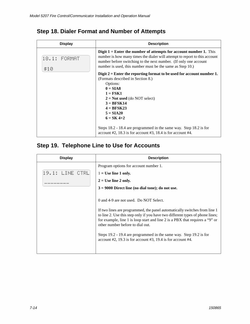
Step 18. Dialer Format and Number of Attempts
Step 19. Telephone Line to Use for Accounts
Display Description
Digit 1 = Enter the number of attempts for account number 1. This number is how many times the dialer will attempt to report to this account number before switching to the next number. (If only one account number is used, this number must be the same as Step 10.)
Digit 2 = Enter the reporting format to be used for account number 1. (Formats described in Section 8.)
Options:0 = SIA81 = FSK12 = Not used (do NOT select)3 = BFSK144 = BFSK235 = SIA206 = SK 4+2
Steps 18.2 - 18.4 are programmed in the same way. Step 18.2 is for account #2, 18.3 is for account #3, 18.4 is for account #4.
Display Description
Program options for account number 1.
1 = Use line 1 only.
2 = Use line 2 only.
3 = 9000 Direct line (no dial tone); do not use.
0 and 4-9 are not used. Do NOT Select.
If two lines are programmed, the panel automatically switches from line 1 to line 2. Use this step only if you have two different types of phone lines; for example, line 1 is loop start and line 2 is a PBX that requires a “9” or other number before to dial out.
Steps 19.2 - 19.4 are programmed in the same way. Step 19.2 is for account #2, 19.3 is for account #3, 19.4 is for account #4.
Programming: Step-by-Step Complete Reference
150865 7-15
Step 20. Duration of Delays
Display Description
Bell Shutdown Time (1-255)Divide by 10 and enter the number indicating the time that you want audio alarms to be active.Example:Suppose you want audio alarms to be active for 900 seconds (or 15 minutes). Enter 900 divided by 10 or “90”.
Common shutdown times: 5 minutes = 300 seconds. Enter “30.”10 minutes = 600 seconds. Enter “60.”15 minutes = 900 seconds. Enter “90.”20 minutes = 1200 seconds. Enter “120.”25 minutes = 1500 seconds. Enter “150.”30 minutes = 1800 seconds. Enter “180.”
Step 20.2 is not used.Do NOT change the factory-programmed setting of “30”.
Use this step to program the duration (1-255 sec.) of the pre-alarm delay.
Use this step to set the duration (1-255 sec.) of the smoke verification delay.
Use this step to program the number of seconds (2-7 sec.) it will take smoke detectors to reset. Refer to the manufacturer’s specification sheet for the times approved for your smoke detectors.
Step 20.6 is not used.Do NOT change the factory-programmed selection of “24.”
Model 5207 Fire Control/Communicator Installation and Operation Manual
7-16 150865
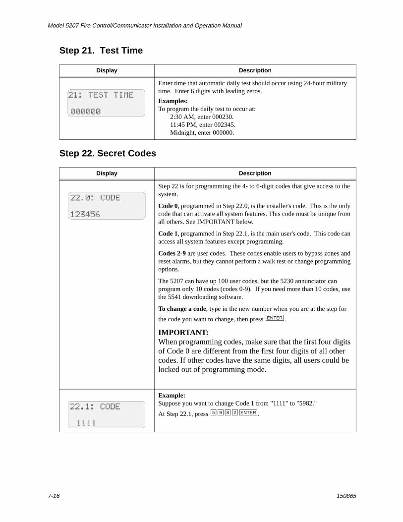
Step 21. Test Time
Step 22. Secret Codes
Display Description
Enter time that automatic daily test should occur using 24-hour military time. Enter 6 digits with leading zeros.
Examples:To program the daily test to occur at:
2:30 AM, enter 000230.11:45 PM, enter 002345.Midnight, enter 000000.
Display Description
Step 22 is for programming the 4- to 6-digit codes that give access to the system.
Code 0, programmed in Step 22.0, is the installer's code. This is the only code that can activate all system features. This code must be unique from all others. See IMPORTANT below.
Code 1, programmed in Step 22.1, is the main user's code. This code can access all system features except programming.
Codes 2-9 are user codes. These codes enable users to bypass zones and reset alarms, but they cannot perform a walk test or change programming options.
The 5207 can have up 100 user codes, but the 5230 annunciator can program only 10 codes (codes 0-9). If you need more than 10 codes, use the 5541 downloading software.
To change a code, type in the new number when you are at the step for
the code you want to change, then press .
IMPORTANT:When programming codes, make sure that the first four digits of Code 0 are different from the first four digits of all other codes. If other codes have the same digits, all users could be locked out of programming mode.
Example:Suppose you want to change Code 1 from "1111" to "5982."
At Step 22.1, press .
ENTER
5 9 8 2 ENTER
Programming: Step-by-Step Complete Reference
150865 7-17
Step 23. Group Relays and BellsIMPORTANT:
You can program relays and bells in either the Group section (Step 23) or the By Zone section (Step 24), but not both.
Relays and bells are programmed for the type of condition that causes them to activate, not by zone. An excep-tion is relays and bells that activate for alarms, which can be programmed by zone. Use Step 24 to program alarm relays and bells by zone.
Display Description
This step selects bells and relays by type of condition. Step 24 is for selecting bells and relays by zone.
Step 23 is used to select the relays and/or bells that you want to activate for particular conditions. This means that relays and/or bells programmed would activate when the specified conditions occurred in a zone.
Digits 1-4 select relays. Digits 5-8 select bells.Step 23.1 selects relays/bells to activate for Pre-alarm conditions.Step 23.2 selects relays/bells to activate for Tamper alarm conditions.Step 23.3 selects relays/bells to activate for Special (Auxiliary) conditions.Step 23.4 selects relays/bells to activate for Fire conditions.Step 23.5 selects relays/bells to activate for Trouble conditions.Step 23.6 selects relays/bells to activate for No Silence conditions.
Example: Use the steps below to program your system for the following:
Pre-alarm condition: Activate Relays 3 and 4 and Bell 1.
Fire: Activate Bells 1, 2, 3, and 4.
Trouble condition: Activate Relays 1 and 2 and Bells 1 and 2.
1. Pre-alarm condition relays/bells are programmed in Step 23.1.
a. Press to select Relay 3
b. Press to select Relay 4
c. Press to select Bell 1Your LCD would appear as shown below:
example continued on next page
3
4
5
Model 5207 Fire Control/Communicator Installation and Operation Manual
7-18 150865
Display Description
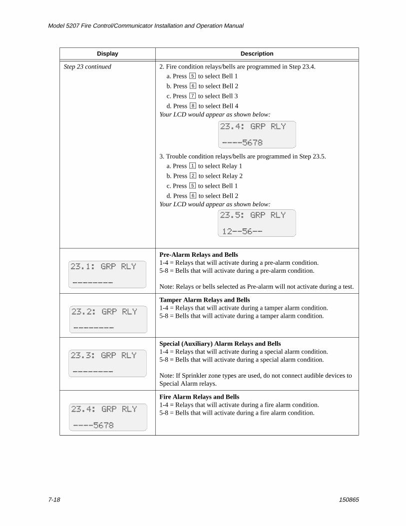
Step 23 continued 2. Fire condition relays/bells are programmed in Step 23.4.
a. Press to select Bell 1
b. Press to select Bell 2
c. Press to select Bell 3
d. Press to select Bell 4Your LCD would appear as shown below:
3. Trouble condition relays/bells are programmed in Step 23.5.
a. Press to select Relay 1
b. Press to select Relay 2
c. Press to select Bell 1
d. Press to select Bell 2Your LCD would appear as shown below:
Pre-Alarm Relays and Bells1-4 = Relays that will activate during a pre-alarm condition.5-8 = Bells that will activate during a pre-alarm condition.
Note: Relays or bells selected as Pre-alarm will not activate during a test.
Tamper Alarm Relays and Bells1-4 = Relays that will activate during a tamper alarm condition.5-8 = Bells that will activate during a tamper alarm condition.
Special (Auxiliary) Alarm Relays and Bells1-4 = Relays that will activate during a special alarm condition.5-8 = Bells that will activate during a special alarm condition.
Note: If Sprinkler zone types are used, do not connect audible devices to Special Alarm relays.
Fire Alarm Relays and Bells1-4 = Relays that will activate during a fire alarm condition.5-8 = Bells that will activate during a fire alarm condition.
5
6
7
8
1
2
5
6
Programming: Step-by-Step Complete Reference
150865 7-19
Step 24. Alarm Relays and Bells (by Zone)
Display Description
Trouble Relays and Bells
1-4 = Relays that activate during a trouble condition.
5-8 = Bells that activate during a trouble condition.
Note: Relays or bells selected as Trouble will not activate during a test.
No Silence Relays and Bells
This option is intended for use with applications such as strobes.
1-4 = Relays that will remain active when the 5207 is silenced. (Alarm relays always remain active until reset.) You can use this step to program a trouble relay to remain active after the panel is silenced. Select the relay that should remain active in this step.
5-8 = Outputs that will remain active when the 5207 is silenced. You can use this step to make sure that strobes on the system continue to activate when bells and horns are silenced. To do this, make sure strobes are on separate outputs from horns and bells, then select the strobe outputs in this step.
Note: If you are using the 5220 Direct Connect Module for supervision, see Section 4.7 for information on programming relays and bells.
Display Description
This step selects bells and relays to activate by zone. Step 23 is for selecting bells and relays by type of condition.
Use this step to select the relays and/or bells that will activate during an alarm condition in each zone. Step 24.0 selects bells and relays to activate during a fire drill ("Zone 0"). Step 24.1 selects bells and relays to activate for an alarm in Zone 1, Step 24.2 selects bells and relays for Zone 2, and so on.
1-4 = Relays that will activate during an alarm in the zone.5-8 = Bells that will activate during an alarm in the zone.
Note: If using the Model 5220 Direct Connect Module for supervision, select Relay 3 for Zone 3. See Section 4.7 for more information.
Model 5207 Fire Control/Communicator Installation and Operation Manual
7-20 150865
Step 25. Zone Types
Display Description
In Steps 25.1 through 25.16, you will program two numbers.
Digit 1 programs the audible signals for the zone.Digit 2 programs the zone type.
Move through the steps to make sure that all zones in your installation have been programmed the way you want them to be. For any zones that require changes, follow the steps for changing zone types as described in the examples above. You can record zone options in the Quick Reference chart in Section 6.
Audible Signal (Step 25, Digit 1)0 = Bells can shut down2 = Cross alarm delay (alarm report delayed until a second alarm occurs on another zone)4 = No manual bell silence (waterflow zones)8 = No automatic bell shutdown (fire zones)
A = Cross alarm and no shutdown. (Press for letter “A”.)
Zone Types (Step 25, Digit 2)0 = Fire Drill1 = Fire (includes waterflow switches, smoke detectors, heat, etc.)3 = Panic5 = Tamper6 = Sprinkler (supervisory zones)7 = Undefined Auxiliary8 = Water (Auxiliary for high or low water)9 = Heat
A = Cold (Press for letter “A”.)
B = Local (not reported) (Press for letter “B”.)C = Not used. Do NOT select.
Example 1:Suppose you want Zone 1 to be a fire type zone with no automatic bell shutdown. At Step 25.1, make sure the digits “81,” the factory-
programmed selections, are displayed. Press if necessary.
Example 2:Suppose you want Zone 2 to be a fire type zone with cross-alarm delayed
and no bell shutdown. Press to select “A” for digit 1 (cross
alarm and no shutdown). Press for Digit 2 to select fire type. Your LCD would appear as shown below.
SHIFT 1
SHIFT 1
SHIFT 2
8 1
SHIFT 1
1
Programming: Step-by-Step Complete Reference
150865 7-21
Step 26. Zone Location Descriptions
Display Description
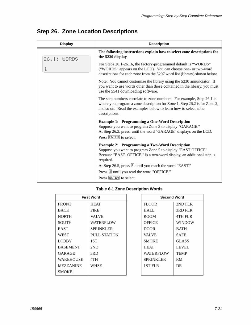
The following instructions explain how to select zone descriptions for the 5230 display.
For Steps 26.1-26.16, the factory-programmed default is “WORDS” (“WORDS” appears on the LCD). You can choose one- or two-word descriptions for each zone from the 5207 word list (library) shown below.
Note: You cannot customize the library using the 5230 annunciator. If you want to use words other than those contained in the library, you must use the 5541 downloading software.
The step numbers correlate to zone numbers. For example, Step 26.1 is where you program a zone description for Zone 1, Step 26.2 is for Zone 2, and so on. Read the examples below to learn how to select zone descriptions.
Example 1: Programming a One-Word DescriptionSuppose you want to program Zone 3 to display "GARAGE."At Step 26.3, press until the word "GARAGE" displays on the LCD.
Press to select.
Example 2: Programming a Two-Word DescriptionSuppose you want to program Zone 5 to display "EAST OFFICE". Because "EAST OFFICE " is a two-word display, an additional step is required.
At Step 26.5, press until you reach the word "EAST.”
Press until you read the word "OFFICE."
Press to select.
Table 6-1 Zone Description Words
First Word Second Word
FRONT HEAT FLOOR 2ND FLR
BACK FIRE HALL 3RD FLR
NORTH VALVE ROOM 4TH FLR
SOUTH WATERFLOW OFFICE WINDOW
EAST SPRINKLER DOOR BATH
WEST PULL STATION VALVE SAFE
LOBBY 1ST SMOKE GLASS
BASEMENT 2ND HEAT LEVEL
GARAGE 3RD WATERFLOW TEMP
WAREHOUSE 4TH SPRINKLER RM
MEZZANINE WHSE 1ST FLR DR
SMOKE
ENTER
1
2
ENTER
Model 5207 Fire Control/Communicator Installation and Operation Manual
7-22 150865
Steps 27 and 28. Temporal Patterns
Display Description
This step programs the length of the pattern.
Steps 27 and 28 are used together to control the temporal (pulsing) pattern of the bell outputs. You can use these steps to create any temporal pattern you want, including the pattern required by NFPA 72.
Step 27 determines the length (number of bits) of the pattern. This number can be 1 to 32, allowing for patterns that are up to 16 seconds (or 32 half-seconds) in duration.
The default setting is 32.
Note: If you are using this step to create a customized temporal pattern, both cadenced pulsing (option 0) and pulse fire bells (option 3) must be enabled in Step 3.
Example 1: Simple two-second patternSuppose you want to create the simple temporal pattern one second ON, one second OFF. In Step 27, you would enter “4” because the length of the pattern is four half-seconds (or two seconds).After programming this example, your LCD would appear as shown below.
See Example 1 in Step 28.1 for setting the pattern.
Example 2: NFPA 72 required patternIn an NFPA 72 installation, the temporal pattern must be ON OFF ON OFF ON OFF OFF OFF. Program Step 27 as shown below to achieve this pattern length.
See Example 2 in Step 28.1 for setting the pattern.
Programming: Step-by-Step Complete Reference
150865 7-23
Display Description
This step selects the actual pattern.
Steps 28.1-28.4 determine the pattern. Select a digit for each half-second ON; de-select a digit (display shows a dash) for each half-second OFF. Each sub-step controls up to four seconds. The pattern you create will repeat as long as the bell output is active.
The default setting is the 32-bit temporal pattern:ON ON ON ON ON ON ON OFFON ON ON ON ON ON ON OFFON ON ON ON ON ON ON OFFOFF OFF OFF OFF OFF OFF OFF OFF
If using the 5541, Y indicates ON and a dash indicates OFF.
Example 1: Simple two-second patternTo create the simple temporal pattern one second ON, one second OFF. In Step 28.1, you would select a digit for each half-second ON and de-select a digit for each half-second OFF as follows:
See Example 1 in Step 27 for setting the length.Note: If using this step to create a customized temporal pattern, both cadenced pulsing (option 0) and pulse fire bells (option 3) must be enabled in Step 3.
Example 2: NFPA 72 required patternIn an NFPA 72 installation, the temporal pattern must be ON OFF ON OFF ON OFF OFF OFF. Program Step 28.1 as shown below to achieve this pattern.