7–1 CM 4000 Installation and Operating Manual Section 7 – Software Control Panel Suite The Software Control Panel Suite (“Graphical User Interface”) consists of seven routing switcher and machine control applications plus a configuration application. Only one of the applications can be activated at a time. Note 1: Activation of the Software Control Panel Suite requires a license floppy disk provided by Thomson. For more information, please refer to the Field Engineering Bulletin supplied with the Jupiter software. Note 2: Some of the panels may not be available, depending on which packages have been purchased. For more information, see page 1–23. The software operates on a PC using the Jupiter Network Suite (JNS) software, which provides the interface to the Jupiter Control system through the Jupiter LAN. The Software Control Panels are designed for mouse or touchscreen opera- tion. § The panels can be run on the Jupiter file server, on one or more separate PCs on the Jupiter LAN, or on both. The control panels obtain configuration set information from the Jupiter control system file server, allowing the user to maintain a central configuration control point even with multiple control panel PCs operating on the LAN. The software provides a means for licensing and operation of multiple copies of the control panel software on a single Jupiter system. Software Installation Software installation is described in the Field Engineering Bulletin supplied with the software. Jupiter Table Entries If the software panels are to be used for switcher control only , no Jupiter table entries are required. However, the panels will require the use of existing CP Level, Input, and Output sets. Note 3: These sets are not assigned to the suite using the MPK Devices table directly. Instead, they are as- signed using the special “Panel Configuration” procedure found later in this section (page 7–7). If the panels are to be used for machine control, a Configuration Set must be selected for editing and entries describing the PC and the machine control panels must be made to the following tables: S Network Description table S Serial Protocol table S MPK Devices table § For touchscreen operation, the PC and monitor must be supplied by Thomson.
Transcript
7–1CM 4000 Installation and Operating Manual
Section 7 – Software Control Panel Suite
The Software Control Panel Suite (“Graphical User Interface”) consists of seven routing switcher and machine controlapplications plus a configuration application. Only one of the applications can be activated at a time.
Note 1: Activation of the Software Control Panel Suite requires a license floppy disk provided by Thomson. Formore information, please refer to the Field Engineering Bulletin supplied with the Jupiter software.
Note 2: Some of the panels may not be available, depending on which packages have been purchased. For moreinformation, see page 1–23.
The software operates on a PC using the Jupiter Network Suite (JNS) software, which provides the interface to the JupiterControl system through the Jupiter LAN. The Software Control Panels are designed for mouse or touchscreen opera-tion.§ The panels can be run on the Jupiter file server, on one or more separate PCs on the Jupiter LAN, or on both.
The control panels obtain configuration set information from the Jupiter control system file server, allowing the user tomaintain a central configuration control point even with multiple control panel PCs operating on the LAN. The softwareprovides a means for licensing and operation of multiple copies of the control panel software on a single Jupiter system.
Software Installation
Software installation is described in the Field Engineering Bulletin supplied with the software.
Jupiter Table Entries
If the software panels are to be used for switcher control only, no Jupiter table entries are required. However, the panelswill require the use of existing CP Level, Input, and Output sets.
Note 3: These sets are not assigned to the suite using the MPK Devices table directly. Instead, they are as-signed using the special “Panel Configuration” procedure found later in this section (page 7–7).
If the panels are to be used for machine control, a Configuration Set must be selected for editing and entries describingthe PC and the machine control panels must be made to the following tables:
� Network Description table
� Serial Protocol table
� MPK Devices table
§ For touchscreen operation, the PC and monitor must be supplied by Thomson.
Software Control Panel Suite
7–2 CM 4000 Installation and Operating Manual
� Machine Control Devices table
These entries are described on the following pages. Guidelines for using the table editor are found on page 5–3.
For information about management of Configuration Sets, including compiling and activating sets, see page 5–8.
NETWORK DESCRIPTION TABLE
Network Description
RednBoard Name
PC1 PC
Address
1
Type
192.168.253.2
Figure 7–1.
Board Name Create a name for the PC that will display the Software Control Panels.
For Jupiter naming rules, see page 5–7.
Type Select board type “PC.”
Address Enter the IP address of the PC (e.g., “192.168.253.2”).
To find out the IP address, go to Start > Programs > Jupiter Network Suite > JNS Configuration.
In some cases, there may be two network cards installed—one for Jupiter and another for a facility LAN.If you are not sure which address is correct for the Jupiter card, try looking at Network Neighborhood >Properties (right click for Properties), then Protocols > TCP/IP Protocol > Properties > Adapter; usuallythe Jupiter card will be a 3Com. Click on 3Com to see the IP address of the card.
Software Control Panel Suite
7–3CM 4000 Installation and Operating Manual
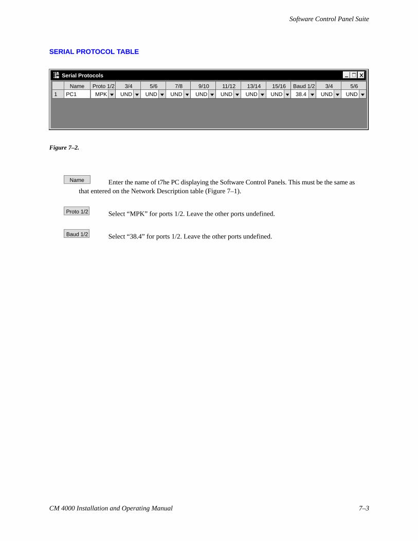
SERIAL PROTOCOL TABLE
Serial Protocols
Proto 1/2Name
PC1 MPK1
3/4
UND
5/6
UND
7/8
UND
9/10
UND
11/12
UND
13/14
UND
15/16
UND
Baud 1/2
38.4
3/4
UND
5/6
UND
Figure 7–2.
Name Enter the name of t7he PC displaying the Software Control Panels. This must be the same asthat entered on the Network Description table (Figure 7–1).
Proto 1/2 Select “MPK” for ports 1/2. Leave the other ports undefined.
Baud 1/2 Select “38.4” for ports 1/2. Leave the other ports undefined.
Software Control Panel Suite
7–4 CM 4000 Installation and Operating Manual
MPK DEVICES TABLE
MPK Devices
1
Dev Name Dev Type Exp PW Board Port Address Inp Set Out Set Lev Set Over Set Seq Set
2
PC1MC2 PC1 1 23232323MC–30003
PC1MC3 PC1 1 45454545MC–30004
PC1MC4 PC1 1 67676767MC–30005
PC1MC5 PC1 1 89898989MC–30006
PC1MC6 PC1 1 90909090MC–3000
N
N
N
N
N
3800 VM1 6 00C19E22CP–3800
PC1MC1 PC1 1 01010101MC–3000
N
N
3800INP 3800OUT 3800LEV
7
Figure 7–3.
Dev Name There must be an entry for at least one CP 3xx or CP 3xxx control panel that has Input, Output,and Level Sets assigned. (A CP 3800 panel is shown in this example.)
You must also create a name for each of the six Slaved Machine Control panels.
Dev Type For the slaved machine control panels, select “MC–3000.”
Exp For the software machine control panels the entry is always “N.”
Board For the slaved machine control panels, enter the name of the PC that will display the softwarepanels; this must agree with the PC’s Board Name entered on the Network Description table (page7–2).
Port For the slaved machine control panels, there must be an entry in each of these fields to satisfythe compiler.
Address For the slaved machine control panels, there must be a unique entry in each of these fields tosatisfy the compiler.
Inp Set Out Set Lev Set These fields are the source for the set names that appear on the Panel Config-uration screen (page 7–7). For the six Slaved Machine Control panel entries, these fields must be blank.
Software Control Panel Suite
7–5CM 4000 Installation and Operating Manual
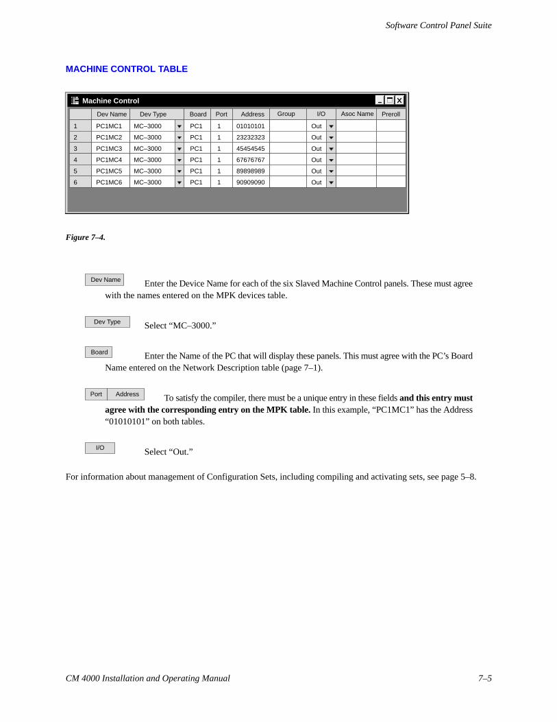
MACHINE CONTROL TABLE
Machine Control
1
Dev Name
PC1MC1
Dev Type
MC–3000
Board
PC1
Port
1
Address
01010101
Group I/O Asoc Name Preroll
MC–3000 Out
2 PC1MC2 MC–3000 PC1 1 23232323MC–3000 Out
3 PC1MC3 MC–3000 PC1 1 45454545MC–3000 Out
4 PC1MC4 MC–3000 PC1 1 67676767MC–3000 Out
5 PC1MC5 MC–3000 PC1 1 89898989MC–3000 Out
6 PC1MC6 MC–3000 PC1 1 90909090MC–3000 Out
Figure 7–4.
Dev Name Enter the Device Name for each of the six Slaved Machine Control panels. These must agreewith the names entered on the MPK devices table.
Dev Type Select “MC–3000.”
Board Enter the Name of the PC that will display these panels. This must agree with the PC’s BoardName entered on the Network Description table (page 7–1).
Port Address To satisfy the compiler, there must be a unique entry in these fields and this entry mustagree with the corresponding entry on the MPK table. In this example, “PC1MC1” has the Address“01010101” on both tables.
I/O Select “Out.”
For information about management of Configuration Sets, including compiling and activating sets, see page 5–8.
Software Control Panel Suite
7–6 CM 4000 Installation and Operating Manual
Main Screen
At the end of the installation process, the Software Panels program can be launched using the JNS Console, in the “JNSApplications” program group. (For more information about the JNS Console, see Section 4.)
Note: If the application can’t find an active set, it will not start. Be sure you have selected a configuration set(as described on page 5–10), and then compiled and activated the set (page 5–13).
Figure 7–5.
The Main Screen provides the ability to access each of the installed GUI applications. The GUI buttons on the screenindicate that the application is configured and ready for use by changing the label text from shaded to black.
Software Control Panel Suite
7–7CM 4000 Installation and Operating Manual
Panel Configuration
When the “Configure” button is selected, a password screen will appear. When the system is first configured, the screenwill have a “New Password” box and a “Confirm Password” box.
— If a password is desired, enter up to eight alphanumeric characters (case sensitive) and re–enter to con-firm. Then select “Apply.” The screen shown in Figure 7–6 will appear.
— If no password is desired, just select “Apply.” The screen shown in Figure 7–6 will appear.
Figure 7–6. Panel Configuration screen.
The Panel Configuration screen displays the CPInput, Output and Level sets found on the activeMPK table. The selected sets will be used for allsoftware panels in the system.
After highlighting the desired sets, select“Back” to activate the sets and return to theMain Screen.
Although the Software Control Panels can usesets originally created§ for any CP 3xx or CP3xxx control panel, the ideal sets would be thosecreated for use with an existing CP 3800 panel.Since such sets can include 20 categories andeight–character mnemonics, they would allowyou to take full advantage of the Software Con-trol Panel’s capabilities.†
Note: the CP Output set selected here must have a least one output assigned to one of the first 16 categoriesin the set, otherwise no output can be selected for control. For example, if a type 3800 output set is selected,it must have at least one output assigned to a category in the outlined group shown in Figure 7–7:
VTR CG NET SAT AVCR CAM REM EMER BFILM PTCH STU FS CAUX TEST MISC SS D
Figure 7–7.
§ In this application, use of sets that were created for one panel type and later copied for use with another type should beavoided.
† If no such sets exist, you may want to create eight–character Input/Output/Level sets of type CP 3800 and assign them to animaginary device of type CP–3800. For information about creating these sets, see CP Level sets (page 5–57), CP Input sets(page 5–60) and CP Output sets (page 5–76). Keep in mind that an imaginary device entered on the MPK table must havecorresponding entries on the Serial Devices table!
Software Control Panel Suite
7–8 CM 4000 Installation and Operating Manual
Operation
Following configuration, any one of the following panels can be selected:
� Slaved Machine Control – provides the ability to send the same command to up to six machines at once.
� Full Function – the Full Function screen provides the user with full–matrix switcher control features in-cluding breakaway, presets, and setup memory.
� Full Function Machine Control – provides the user with full function control, including time code markand search, of one machine at a time.
� Dubs – provides the ability to switch the same source to multiple destinations with a single Take.
� Source / Destination – the Source/Destination panel provides full–matrix routing switcher control usingCategory and Entry buttons.
� Salvo – the Salvo screen provides the ability to switch multiple source/destination combinations with asingle Take.
� X–Y Panel – similar to Source / Destination panel but with one set of category and entry buttons for thesource and another set for the destination.
Each of these panels is described in the following pages.
If you have a large system, it can take quite a while for the system to apply configuration data to a panel when you firststart it. If you are running remotely, the delay will be somewhat longer because the panel must load configurationinformation from the file server. This delay can be made worse if you have a lot of applications running on the file server.The Jupiter Configuration Editor in particular requires a large amount of processor time. If you are running GUI panelseither on the file server, or remotely, you should close the Jupiter Configuration Editor. In addition, you should closedown any unnecessary applications on the file server.
After a panel is started, select the Back button to return to the Main screen.
To switch between windows, press ALT+TAB. To return to the software panel, click anywhere within the panel display.
On some computers, you can display the Windows task bar on the bottom of the screen by pressing the Windows logokey and TAB. (You can’t minimize the Software Control Panel screen.)
Paths Full / Protected / Locked / Excluded Messages
These messages will be shown for approximately four seconds if a switch fails for one of these reasons. This applies to theFull Panel, X–Y Panel, Source Destination Panel and the Dubs Panel. “Paths Full” means that no Tie Lines are available;“Protected” means the output is protected by another panel; “Locked” means the output is locked by another panel; “Ex-cluded” means the switch is prohibited by an entry in the Exclusion table. All GUI Panels that are on the same output asthe GUI Panel that requested the switch will display these messages. For additional Protect/lock information see page6–12.
Software Control Panel Suite
7–9CM 4000 Installation and Operating Manual
SLAVED MACHINE CONTROL PANEL
Figure 7–8.
The Slaved Machine Control panel provides the ability to control up to six machines from a single screen. The panelincludes a Gang button for slaving machines together.
Machine Assignment
To link to a machine, select the “Machine” window; a drop down list will show the machines entered on the MachineControl table of the active configuration set (see page 5–125).
Note: The GUI machine control panels are linked (assigned) directly to individual machines using the Ma-chine drop–down window. It is not necessary to use the “Associated Name” linkage method used for hardwarecontrol panels such as the MC 3000 (that method, sometimes referred to as “control–follow–router,” is de-scribed on page 5–131).
Select the desired machine. If linkage is established, the appropriate motion control button will turn yellow; if time codeis present it will be displayed as well.
If an attempt is made to take control of a machine that has a “default” (semi–permanent) link to a specific control panel,the link will not occur; instead, a message will indicate the name of the controlling device. For more information aboutdefault links, see page 5–136.
Software Control Panel Suite
7–10 CM 4000 Installation and Operating Manual
Machine Control Buttons
Gang Allows a machine control command to be sent to more than one machine.
Stop Stops machine regardless of mode
Play Playback mode. May or may not override current mode, depending on machine.
Record Immediately begins recording
REW or FF Full speed shuttle (rewind or fast forward)
Ready Toggles the machine in and out of scanner ready mode
Time code display
The time code display window will display hours, minutes, seconds and frames. In some modes the frames are not dis-played.
Software Control Panel Suite
7–11CM 4000 Installation and Operating Manual
FULL FUNCTION SWITCHER PANEL
Multi–level StatusMulti–level Preset
Level 1 PresetLevel 1 Status
Figure 7–9.
This panel provides full matrix control with breakaway switching capability. Memories allow the user to Save/Recallup to four sets of 12 Direct Take inputs per output.
To Status a Destination
1. Select the Destination button.
The Categories section will be rewritten to display the categories available to the operator, up to a maximum of 16.The Function buttons will change from white to gray to indicate they are inactive.
2. Select the desired Category button.
The Entries section will be rewritten to display up to 15 destination buttons. Additional Destination buttons, if avail-able are accessed by using the scroll buttons.
3. Select the desired Entry button.
The destination entry will be entered into the Destination display and the level 1 status will be shown in the Statuswindow. In addition, the status for each level will be shown in the “Levels” window with yellow lettering; the nameof each level will be shown on the buttons. If more than four levels exist a scroll button will appear.
Software Control Panel Suite
7–12 CM 4000 Installation and Operating Manual
To Switch a Source
1. Select the Source button.
The Categories section will be rewritten to display all source categories available to the operator. The Function but-tons will change from gray to white to indicate they are active.
2. Select the desired Source Category button.
The Source Entries section will be rewritten to display up to 15 source buttons. Additional Source buttons, if avail-able, are accessed by using the scroll buttons.
3. Select the desired Source Entries button. The source entry (level 1) will be entered into the Preset display. In addi-tion, the preset source for each level will appear in the “Levels” window with green lettering.
4. Select Take to execute the switch.
The Status display will change to the new source indicating the switch was made. The Preset display will changeto the previously selected source. Flip–flop switching between the old and new source is accomplished by pressingthe Take button again.
Paths Full / Protected / Locked / Excluded messages – see page 7–8.
Breakaway Switching (“Select” Method)
When only one level is to be switched, the following method is suggested:
— If the destination needs to be changed, select it at this time.
— The “Source” button lettering should be yellow (active). If not, select it.
— The Preset windows should be blank. If not, click the Clear All button. Then:
1. Select the desired Level button. A dark line will appear around the button.
2. Choose the desired source Category and Entry.
The name of the source will appear above the Level button just selected.
3. Click the Take button.
The name of the source will move to the multi–level status window.
Flip–flop switching between the old and new source is accomplished by pressing the Take button again.
Software Control Panel Suite
7–13CM 4000 Installation and Operating Manual
Breakaway Switching (“Deselect” Method)
When more than one level is to be switched, the following method is suggested:
— If the destination needs to be changed, select it at this time.
— The “Source” button lettering should be yellow (active). If not, select it.
1. Choose the first source Category and Entry.
The name of the source will appear above all the Level buttons.
2. Deselect the Level button(s) for the level(s) not receiving this source.
This will erase the name of the source above the Level buttons just deselected.
3. Choose the the next source Category and Entry.
4. Deselect the Level button(s) for the level(s) not receiving this source.
5. Repeat until all sources are selected.
6. Click the Take button.
The names of the new sources will move to the multi–level status window.
Flip–flop switching between the old and new sources is accomplished by pressing the Take button again.
Software Control Panel Suite
7–14 CM 4000 Installation and Operating Manual
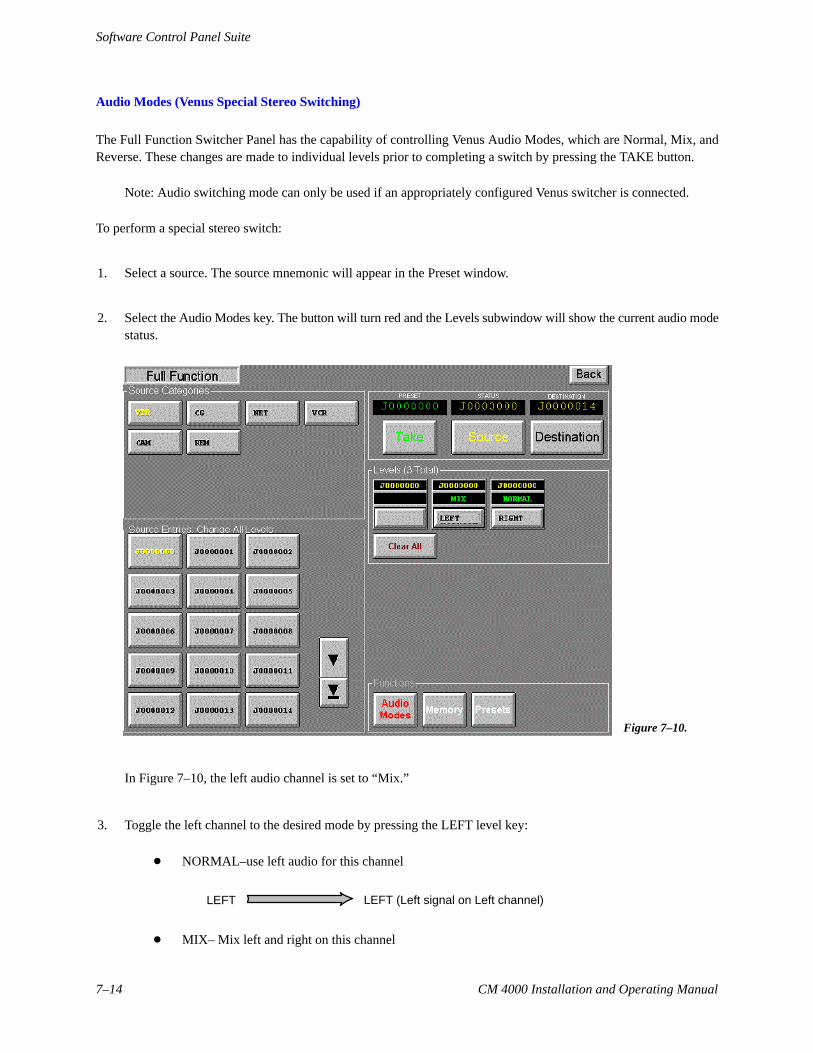
Audio Modes (Venus Special Stereo Switching)
The Full Function Switcher Panel has the capability of controlling Venus Audio Modes, which are Normal, Mix, andReverse. These changes are made to individual levels prior to completing a switch by pressing the TAKE button.
Note: Audio switching mode can only be used if an appropriately configured Venus switcher is connected.
To perform a special stereo switch:
1. Select a source. The source mnemonic will appear in the Preset window.
2. Select the Audio Modes key. The button will turn red and the Levels subwindow will show the current audio modestatus.
Figure 7–10.
In Figure 7–10, the left audio channel is set to “Mix.”
3. Toggle the left channel to the desired mode by pressing the LEFT level key:
� NORMAL–use left audio for this channel
LEFT LEFT (Left signal on Left channel)
� MIX– Mix left and right on this channel
Software Control Panel Suite
7–15CM 4000 Installation and Operating Manual
LEFT
RIGHT
LEFT (Left + Right signals on Left channel)
� REVERSE– Cross opposite channel signal over to this channel
RIGHT
LEFT (Right signal on Left channel)
4. Toggle the right channel to the desired mode:
� NORMAL–use right audio for this channel
RIGHT RIGHT (Right signal on Right channel)
� MIX– Mix left and right on this channel
LEFT
RIGHT RIGHT (Left + Right signals on Right channel)
� REVERSE– Cross opposite channel signal over to this channel
LEFT
RIGHT (Left signal on Right channel)
5. Press TAKE.
A letter “M” (mix) or “R” (reverse) will appear in the Levels Status display.
To clear the special mode, perform another switch (with the Audio Modes button off).
Software Control Panel Suite
7–16 CM 4000 Installation and Operating Manual
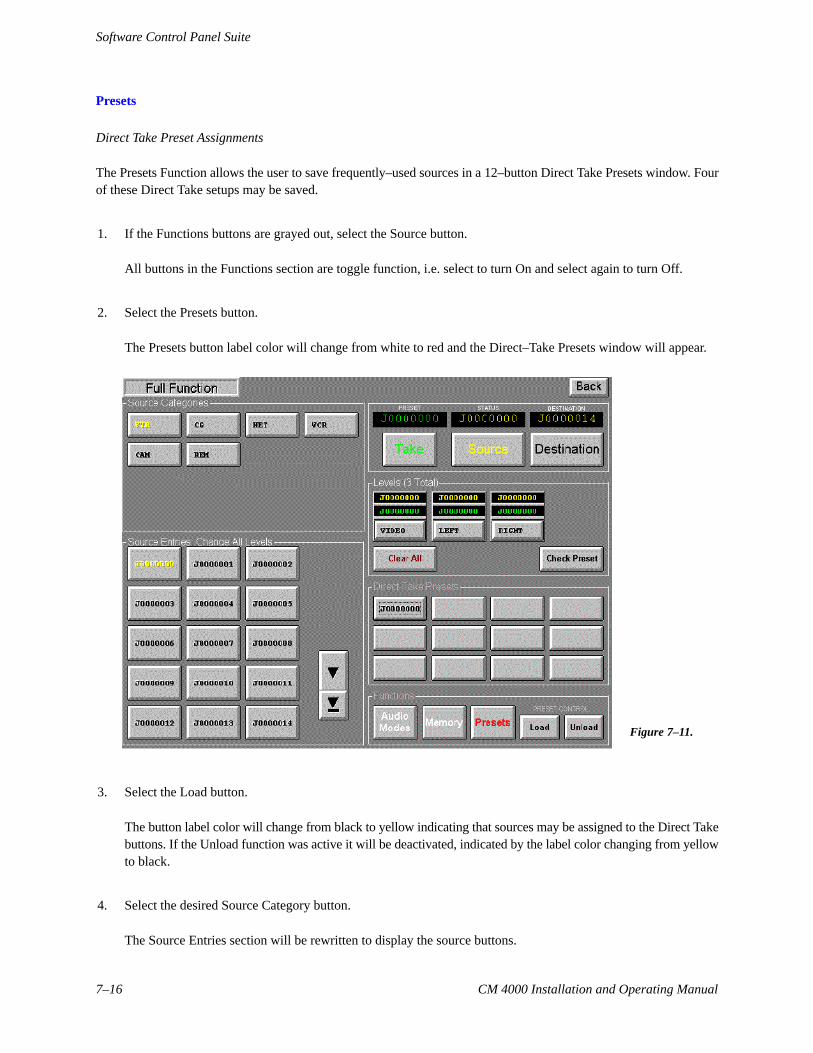
Presets
Direct Take Preset Assignments
The Presets Function allows the user to save frequently–used sources in a 12–button Direct Take Presets window. Fourof these Direct Take setups may be saved.
1. If the Functions buttons are grayed out, select the Source button.
All buttons in the Functions section are toggle function, i.e. select to turn On and select again to turn Off.
2. Select the Presets button.
The Presets button label color will change from white to red and the Direct–Take Presets window will appear.
Figure 7–11.
3. Select the Load button.
The button label color will change from black to yellow indicating that sources may be assigned to the Direct Takebuttons. If the Unload function was active it will be deactivated, indicated by the label color changing from yellowto black.
4. Select the desired Source Category button.
The Source Entries section will be rewritten to display the source buttons.
Software Control Panel Suite
7–17CM 4000 Installation and Operating Manual
5. Select the desired Source Entry button.
The source entry will be entered into the Preset display.
6. Select the desired Direct Take button.
The Source name will be written to the button.
7. Repeat the above steps as required.
A Direct Take button may be reassigned to a new source using the normal assignment procedure.
8. To make a Direct Take assignment permanent, follow the “Memory” procedure below.
Direct Take assignments that are not saved in Memory will be erased when you exit the Software Control Panelapplication.
Breakaway Preset Assignments
To assign Breakaway Selections to Direct Take buttons, follow the “Breakaway Switching” procedure on page 7–12 ex-cept for selecting Take at the end. Instead, select the Presets and Load buttons and then the desired Direct Take buttonto assign the breakaway selection. The Direct Take button source label will be displayed as red characters indicating thata breakaway switch is assigned to this button.
The breakaway setup may be checked on any Direct Take button by activating the Presets window, then the Levels win-dow, and selecting the Check Preset button. The Check Preset button label color will change from black to yellow indicat-ing the function is active. Select the Direct Take button of the source to be checked. The source names will be shownon the Level buttons. The Check Preset button will change from yellow to black indicating the function is no longer ac-tive.
Removing a Preset Assignment
To remove a source from a Direct Take button, select Unload in the Functions section. The button label color will changefrom black to yellow indicating the function is active. If the Load function was active, it will be deactivated, indicatedby the label color changing from yellow to black.
Select the desired Direct Take button. The source name on this button will be cleared. The Unload button label color willchange from yellow to black indicating the function is no longer active.
Switching Using the Direct–Take Presets
Select the Presets button in the functions section. The button label color will change from white to yellow and the DirectTakes section will be displayed. Select the desired Direct Take button. The switch will be immediate.
The Status display will change to the new source indicating the switch was made. The Preset display will change to thepreviously selected source.
Software Control Panel Suite
7–18 CM 4000 Installation and Operating Manual
Switching using the Categories/Source Entries section remains active.
Memory
The memory window allows the user to save or recall up to four sets of 12 Direct Take setups.
Saving a Direct Take Setup
Note: Saved presets for a given configuration set may not be valid with other configuration sets. For example, ifa preset calls for input ”VTR1” and “VTR1” does not appear in a set downloaded at a later time the preset will fail.
1. Follow the Direct Take Preset Assignments procedure above to set up the Direct–Take selections to be saved.
2. With the Direct–Take window open, select the Memory button.
The Memory button label color will change from white to red and the Memory window will appear.
Figure 7–12.
3. Select the desired Memory location (1, 2, 3, or 4).
The label will change from black to yellow.
4. Select Store.
The setup will be saved in the selected location. Also, a “Recall” and a “Clear” button will now appear.
Software Control Panel Suite
7–19CM 4000 Installation and Operating Manual
Recalling a Direct Take Setup
1. Select the destination by following the Status a Destination procedure above (page 7–11).
2. Select the Source button.
The Categories section will be rewritten to display all source categories available to the operator. The Function but-tons label color will change from gray to white to indicate they are active.
3. Select Memory.
The Memory button label color will change from white to red and the Memory window will appear.
4. Select the desired Memory location (1, 2, 3, or 4) to recall the Direct Take setup.
The Memory button selected will change from black to yellow.
5. Select Recall.
The Memory button label will change from red to white and the Memory store window will be replaced with theDirect Take display window which will contain the recalled Direct Take setup entries.
Memory Location Labeling
Note: This feature requires that the GUI PC includes a keyboard.
Select the Memory button, then select the label adjacent to the desired Memory 1, 2, 3, or 4 button. Use the computerkeyboard to enter an 8 character (minimum) user specified name. Select Store. Select Memory to close the display win-dow.
Software Control Panel Suite
7–20 CM 4000 Installation and Operating Manual
FULL FUNCTION MACHINE CONTROL
Figure 7–13.
The Full Function Machine Control screen provides the user with control of one machine at a time. The screen includesan eight–character display for selecting and displaying current machine linkage, twelve machine control buttons, a nu-meric keypad for entering time code values, a time code readout, and a motion control knob with direction and speedindicators.
Machine Assignment
To link to a machine, select the “Machine” window; a drop down list will show the machines entered on the MachineControl table of the active configuration set (see page 5–125).
Note: The GUI machine control panels are linked (assigned) directly to individual machines using the Ma-chine drop–down window. It is not necessary to use the “Associated Name” linkage method used for hardwarecontrol panels such as the MC 3000 (that method, sometimes referred to as “control–follow–router,” is de-scribed on page 5–131).
Select the desired machine. If linkage is established, the appropriate motion control button will turn yellow; if time codeis present it will be displayed as well.
If an attempt is made to take control of a machine that has a “default” (semi–permanent) link to a specific control panel,the link will not occur; instead, a message will indicate the name of the controlling device. For more information aboutdefault links, see page 5–136.
Software Control Panel Suite
7–21CM 4000 Installation and Operating Manual
Machine Control Buttons
Ready Toggles the machine in and out of scanner ready mode.
Stop Stops machine regardless of mode.
Play Playback mode. May or may not override current mode, depending on machine. Shuttleknob remains centered.
Record Immediately begins recording.
Search Go to the time code point captured with Mark, minus the Preroll value set on the Ma-chine Control Devices table.
REW or FF Full speed shuttle (rewind or fast forward). Control knob remains centered.
Go To Go to the time code entered using the keypad.
Mark Captures current time code if the system uses serial time code interface and time code isbeing fed from machine.
Rec In Immediately begins recording.
Rec Out Exit Record mode (same as ESbus Exit command). Normally used to terminate an In-sert edit, in which case the machine drops out of record mode but keeps on playing.
Mode (When enabled) Select a recording mode:
Off = record Inhibit.
Manual = pressing REC IN followed by PLAY will begin a recording, duringwhich no editing functions will be enabled.
Assemble = pressing PLAY and REC IN will begin an Assemble edit.
Insert = pressing PLAY and REC IN will begin an Insert edit.
Control Knob and Direction/speed Indicators
The control knob and and the direction/speed indicators are used for the Variable play, Rewind, and Fast Forward andfunctions. The shuttle function is controlled by rotating the control knob. Stop by pressing the top center mark or the Stopbutton.
Time Code Display
The time code display window will display hours, minutes, seconds and frames. In some modes, the frames are not dis-played.
Manual Time Code Entry
The keypad is used to enter an eight–digit time code; the Go To button can then be used to move to that time.
Software Control Panel Suite
7–22 CM 4000 Installation and Operating Manual
DUBS PANEL
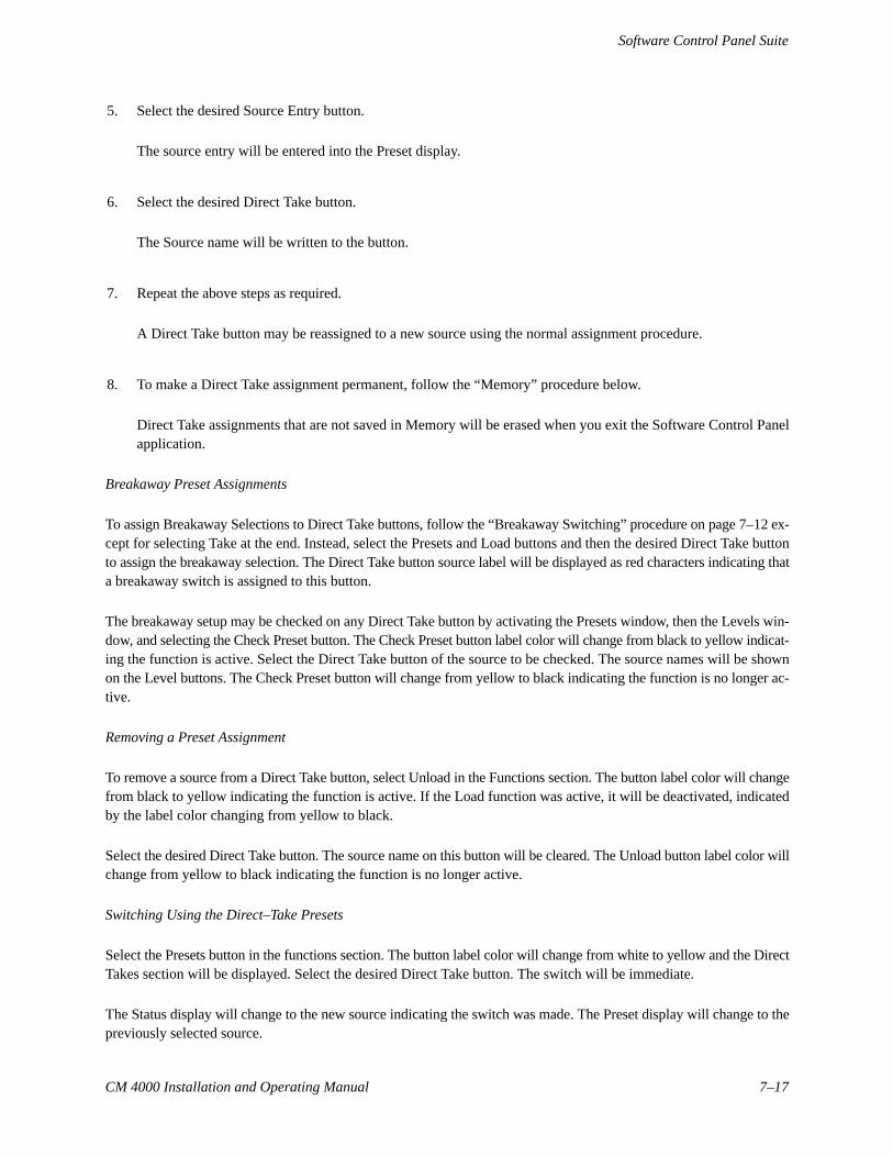
Figure 7–14.
The Dubs screen provides the ability to switch the same source to multiple destinations with a single Take.
To Status a Destination
1. Select the desired Destination button. The status of the current output will be shown in the Status window.
Additional Destination buttons, if available, are accessed by using the scroll buttons. The label of the selected but-ton will change from black to yellow and the entry name will be written in the Destination display. The panel Statusdisplay will always indicate the source status for the last activated destination button.
Software Control Panel Suite
7–23CM 4000 Installation and Operating Manual
Switching Multiple Destinations to the Same Input (Dub Switching)
1. Select the appropriate Destination buttons.
Additional Destination Entries buttons, if available, are accessed by using the scroll buttons. The label of the se-lected buttons will change from black to yellow and the entry name of the last destination selected will be writtenin the Destination display. The Status display will be rewritten to provide current source status.
To cancel a single output selection, select that button again.
To cancel all Destination Entries select Clear.
2. Select the desired Source Category button.
The Source Entries section will be rewritten to display up to 12 source buttons.
3. Select the desired Source Entry button.
The source entry will be entered into the Source Preset display.
4. Select Take to execute the switch.
The Status display will change to the new source indicating the switch was made. The Preset display will changeto the previously selected source. Flip–flop switching between the old and new source will be accomplished byselecting the Take button again.
Paths Full / Protected / Locked / Excluded Messages – see page 7–8.
Using the Hold Button
When Hold is pressed, the button label will change from white to red indicating that the selections made in the DestinationEntries section cannot be inadvertently changed.
Select the Hold button again to toggle the function off. The Hold button label will change from red to white indicatingthe Hold function has been disabled and the selections in the Destinations Entries section can be modified.
Software Control Panel Suite
7–24 CM 4000 Installation and Operating Manual
SOURCE/DESTINATION PANEL
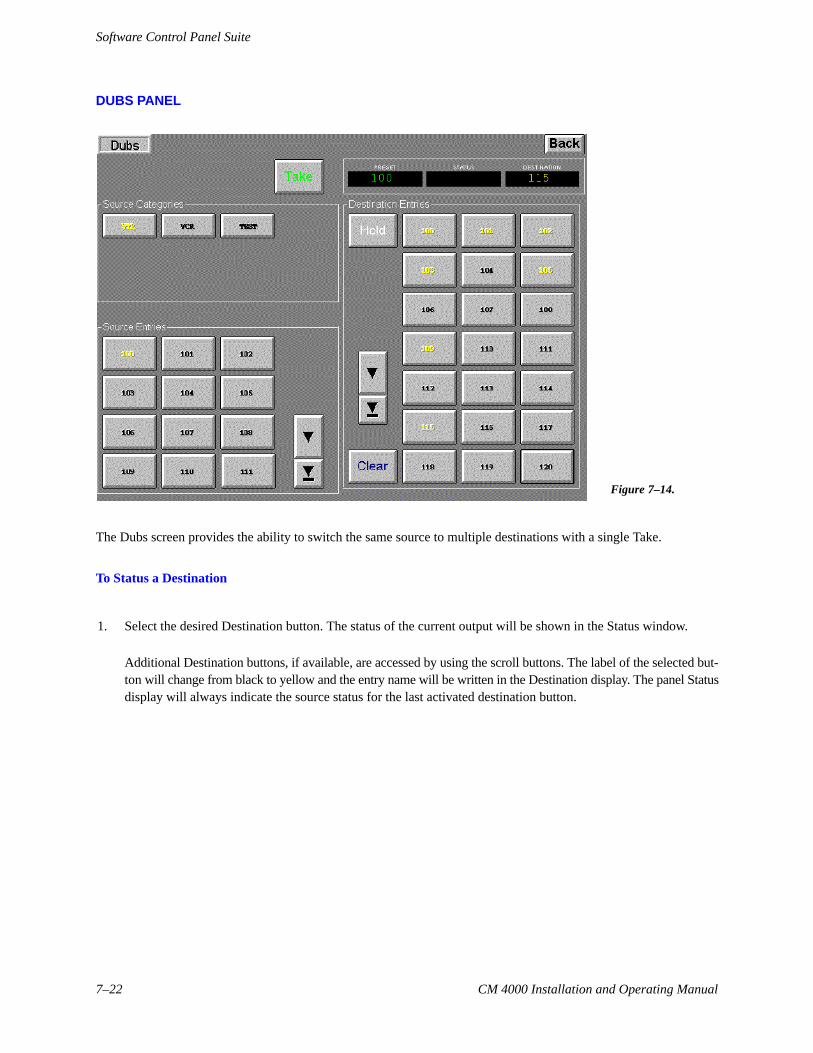
Figure 7–15.
The Source/Destination panel provides full–matrix routing switcher control using Category and Entry buttons.
To Status a Destination
1. Select the Destination button.
The Categories section will be rewritten to display all categories available to the operator.
2. Select the desired Category button.
The Entries section will be rewritten to display up to 24 destination buttons. Additional Destination buttons, ifavailable, are accessed by using the scroll buttons.
3. Select the desired “Entries” button.
The destination entry will be entered into the Destination display and the Source display will be rewritten to providecurrent status.
To Switch a Source
1. Select the desired Destination.
Software Control Panel Suite
7–25CM 4000 Installation and Operating Manual
For more information, see “To Status a Destination” above.
2. Select the Source button.
The Categories section will be rewritten to display all categories available to the operator.
3. Select the desired Source Category button.
The Source Entries section will be rewritten to display up to 24 source buttons. Additional Source buttons, if avail-able, are accessed by using the scroll buttons.
4. Select the desired “Source Entries” button.
The source entry will be entered into the Preset display.
5. Select Take to execute the switch.
The Status display will change to the new source indicating the switch was made. The Preset display will changeto the previously selected source. Flip–flop switching between the old and new source is accomplished by pressingthe Take button again.
Paths Full / Protected / Locked / Excluded Messages – see page 7–8.
Software Control Panel Suite
7–26 CM 4000 Installation and Operating Manual
SALVO PANEL
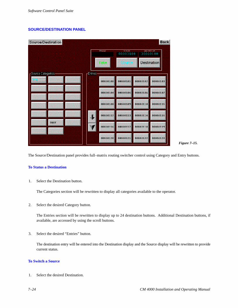
Figure 7–16.
The Salvo screen provides the ability to switch multiple source/destination combinations with a single Take.
Multiple Source/Destination Switching (Salvo)
1. The Salvo Setup function should be On (indicated by a red button label) and the Mem function should be Off (indi-cated by a black button label).
2. Select the first desired Source Entry button.
Additional Source Entries buttons, if available, are accessed by using the scroll buttons. The label of the selectedbutton will change from black to yellow. Selection of a different source will deselect the previous source selection.
3. Select the desired “Destination Entries” buttons.
Each source/destination entry will be entered automatically in the Salvo list window in the lower center of the dis-play.
Additional Destination Entries buttons, if available, are accessed by using the scroll buttons. The label of the se-lected button will change from black to yellow. Additional destinations can be switched to the currently selectedsource by selecting the desired Destination Entries buttons. The button label will change from black to yellow foreach selected destination. To remove a destination from the switch setup select that button again. This will deselectthat output and change the button label from yellow to black.
Software Control Panel Suite
7–27CM 4000 Installation and Operating Manual
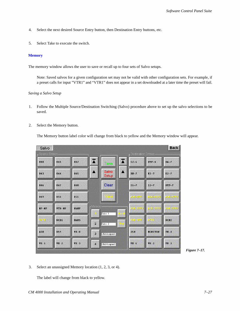
4. Select the next desired Source Entry button, then Destination Entry buttons, etc.
5. Select Take to execute the switch.
Memory
The memory window allows the user to save or recall up to four sets of Salvo setups.
Note: Saved salvos for a given configuration set may not be valid with other configuration sets. For example, ifa preset calls for input ”VTR1” and “VTR1” does not appear in a set downloaded at a later time the preset will fail.
Saving a Salvo Setup
1. Follow the Multiple Source/Destination Switching (Salvo) procedure above to set up the salvo selections to besaved.
2. Select the Memory button.
The Memory button label color will change from black to yellow and the Memory window will appear.
Figure 7–17.
3. Select an unassigned Memory location (1, 2, 3, or 4).
The label will change from black to yellow.
Software Control Panel Suite
7–28 CM 4000 Installation and Operating Manual
4. Select Store.
The setup will be saved in the selected location.
Checking a Salvo Setup
1. Select Memory.
2. Select the desired Memory location (1, 2, 3, or 4).
3. Select Recall.
Recalling and taking a Salvo Setup
1. Select Memory.
2. Select the desired Memory location (1, 2, 3, or 4).
3. Select Recall.
4. Select Take to execute the switch.
Memory Location labeling
Note: This feature requires that the GUI PC includes a keyboard.
Select the Memory button, then select the label adjacent to the desired Memory 1, 2, 3, or 4 button. Use the keyboardto enter an 8 character (minimum) user specified name. Select Memory to close the display window.
Software Control Panel Suite
7–29CM 4000 Installation and Operating Manual
X – Y PANEL
Figure 7–18.
The X–Y Panel is similar to the Source/Destination panel but has one set of category and entry buttons for the sourceand another set for the destination.
To Status a Destination
1. Select the desired Destination Category button.
The Destination Entries section will be rewritten to display up to 12 destination buttons. Additional Destinationbuttons, if available, are accessed by using the scroll buttons. Status for the first level will be shown on the button.
If the button is selected, the destination will also appear in the Destination display and the Current Source displaywill indicate current status.
To Switch a Source
1. Select the desired Destination Category and Entry.
2. Select the Source Category and Entry.
The selection will appear in the Source Preset display.
Software Control Panel Suite
7–30 CM 4000 Installation and Operating Manual
3. Select Take to execute the switch.
The Current Source display will change to the new source indicating the switch was made. The Preset display willchange to the previously selected source. Flip–flop switching between the old and new source will be accomplishedby pressing the Take button again.
Paths Full / Protected / Locked / Excluded Messages – see page 7–8.


![SK9822 REV.01 EN [兼容模张] · 2016. 3. 18. · 3/ 12 SK9822 SK9822: The default is RGB chips with IC integration 6. General Information](https://static.documents.pub/doc/80x56/60c8dd7214333e138a661027/sk9822-rev01-en-fafff-2016-3-18.jpg)


