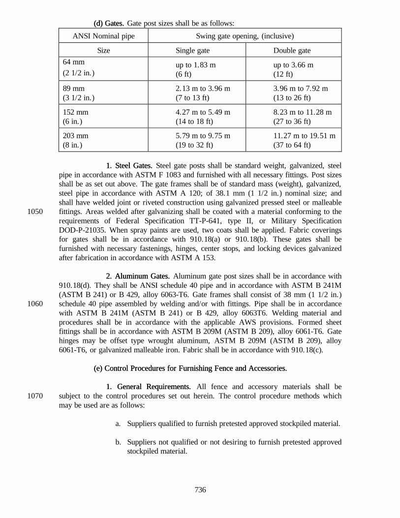
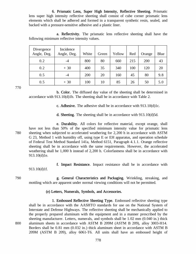
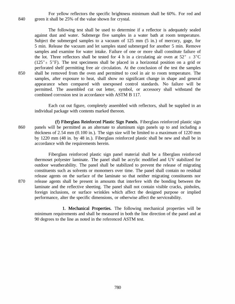
SECTION 901 -- HYDRAULIC CEMENT AND POZZOLANSSECTION 901 -- HYDRAULIC CEMENT AND POZZOLANS
901.01 Hydraulic Cement901.01 Hydraulic Cement..
(a) General(a) General.. At the time cement is incorporated into the work, it shall meetthe quality requirements of these specifications.
Cement which has been in storage may be tested prior to use, and if tests showthat it does not meet the requirements specified it will be rejected.
10A means for storing and protecting the cement against dampness shall be
provided. Cement which has become partially set or which contains lumps or cakedcement will be rejected. Cement salvaged from discarded or used sacks shall not beused.
Different kinds or brands of cement, or cement of the same brand from differentmills, even if tested and approved, shall not be mixed during use unless permitted, andthen only as directed. They shall not be used alternately in any one pour for anystructure, unless otherwise permitted.
20(b) Portland Cement(b) Portland Cement.. Portland cement shall conform to the requirements of
the following cited specifications except as noted.
1. Requirements1. Requirements..
CementCement SpecificationsSpecifications
Air-Entraining Portland Blast-Furnace Slag Cement.........................................AASHTO M 240, Type ISAAir-Entraining Portland Cement .............AASHTO M 85, Type IA or IIIA30Air-Entraining Portland-Pozzolan Cement ..............................................AASHTO M 240, Type IP-APortland Blast-Furnace Slag Cement ................ AASHTO M 240, Type ISPortland Cement................................ AASHTO M 85, Type I, II or IIIPortland-Pozzolan Cement ............................AASHTO M 240, Type IP
The exceptions to AASHTO M 240 are as follows:
a. The amount of pozzolan shall be limited to 20% " 5% by weightof the portland-pozzolan cement for the types IP and IP-A.40
b. The pozzolan in the portland-pozzolan cements, types IP andIP-A, shall be in accordance with ASTM C 618, class C or classF with the loss on ignition of the pozzolan limited to a maximumof 3%.
c. The pozzolan in the portland-pozzolan cements, types IP andIP-A, shall be interground with the portland cement clinker.
641
2. Acceptance Criteria2. Acceptance Criteria. . Portland cements and blended cements will be50accepted based upon the manufacturer's or manufacturer/distributor's documentedability to consistently furnish these materials in accordance with the applicableAASHTO requirements.
a. General Requirementsa. General Requirements.. Cements shall comply with the applicablerequirements of 901 and will be accepted by certification from qualified manufacturersor manufacturer/distributor. The manufacturer is defined as the plant producing thecement. A manufacturer or manufacturer/distributor shall become qualified byestablishing a history of satisfactory quality control of cement produced as evidenced byresults of tests performed by a testing laboratory which is regularly inspected by the60Cement and Concrete Reference Laboratory of the National Institute of Standards andTechnology. Proof of such inspection shall be furnished upon request. All certificationsshall be prepared by the manufacturer or distributor in accordance with the applicablerequirements of 916. If a manufacturer or distributor elects to supply portland cementwith a high sulfur trioxide content in accordance with footnote B from Table 1 inAASHTO M 85, it shall supply all of the required supporting data to the Materials andTests Division prior to supplying such cement. A list of qualified manufacturers andmanufacturer/distributors will be maintained by the Department.
The manufacturer or manufacturer/distributor shall conduct sufficient tests to70ensure that adequate quality control is maintained and that cement furnished is inaccordance with the specification requirements. Documentation pertaining to cementshipped on certification shall be maintained for a period of at least three years and shallbe provided when requested.
Random samples of cement will be obtained at the concrete plant. If the sampleis not in accordance with the specification requirements, an investigation will beconducted. A copy of the findings and conclusions resulting from the investigation willbe furnished to the Contractor. Unless the investigation finds the Department isresponsible for the failure to comply, the cost of the investigation plus any required80corrective action will be assessed to the Contractor.
b. Requirements for Domestic Source Qualificationb. Requirements for Domestic Source Qualification.. Cementmanufacturers requesting to be qualified to supply cement shall provide the following:
(1) For the initial qualification, the manufacturer shall provide tothe Materials and Tests Division an outline of their qualitycontrol procedure including the location and type of samplestaken, and a monthly summary of mill test data for theprevious years production. A current Material Safety Data90Sheet shall be submitted as an integral part of the initialqualification package.
(2) To maintain qualification, a monthly average of mill test datashall be submitted to the Materials and Tests Division. If aspecific type of cement is not manufactured in a given month,the monthly submittal shall state "No type ______ cement wasmanufactured during the month of ____________ 19____".
642
c. Requirements for Foreign Source Qualificationc. Requirements for Foreign Source Qualification.. Foreign cement100manufacturers or their domestic distributors requesting to be qualified to supply cementshall provide the following:
(1) For the initial qualifications, the manufacturer and distributorshall provide to the Materials and Tests Division an outline oftheir quality control procedures including the location and typeof samples taken, and a summary of complete test results fromthe proposed cement source. A current Material Safety DataSheet shall be submitted as an integral part of the initialqualification package. The quality control procedure must110explain the linkage between the cement being furnished andthe manufacturer's/distributor's quality control data, relative toship-loads, barge-loads, railroad car-loads, etc.
(2) Once the initial qualifications have been met, the manufactureror distributor shall be required to furnish the cement testresults for each shipment prior to Department cement usagefor the first five cement shipments, which are intended forDepartment use. The test results for all five of these cementshipments must fully comply with the required material120specifications. If not, this requirement will be continued forsubsequent cement shipments until five consecutive cementshipment test results fully comply with the required materialspecifications, or Department source approval is withdrawndue to the inablity to consistently supply satisfactory cement.
(3) To maintain qualification after compliance with the previousrequirements, a monthly submission of all cement shipmenttest results for cement which is intended for Department usageshall be submitted to the Materials and Tests Division. If no130cement shipments are received during a given month, themonthly submittal shall state "No cement was received duringthe month of ________, 19___."
d. Certificationd. Certification.. Only qualified manufacturers andmanufacturer/distributors as identified by the Department's list of qualifiedmanufacturers and manufacturer/distributors may furnish cement on certification.
A sample certification form addressing all of the required information isincluded in ITM 804. Alternate procedures and forms will be considered when140requested, and will be approved if there is a positive link between the cement furnishedand the manufacturer's quality control data.
(c) Masonry Cement(c) Masonry Cement.. Masonry cement shall be in accordance withASTM C 91, except the air content test and the water retention test may be waived.
901.02 Fly Ash Used as a 901.02 Fly Ash Used as a PozzolanPozzolan..
643
(a) General(a) General.. Fly ash is the finely divided residue that results from thecombustion of ground or powdered coal. In general, class F fly ash is produced from150burning anthracite or bituminous coal and class C fly ash is produced from burninglignite or subbituminous coal.
Fly ash will be accepted from one of the sources on the Department's list ofapproved fly ash and ground granulated blast furnace slag sources. Fly ash fromdifferent sources or different types of fly ash shall not be mixed or used alternately inthe same construction unless authorized in writing. Fly ash will be subject to randomassurance sampling and testing by the Department. Failure of these random samples tomeet the specified requirements will be cause for suspension of the fly ash sourceapproval.160
(b) Acceptance Criteria(b) Acceptance Criteria.. Acceptance is based upon the supplier'sdocumented ability to consistently furnish material in accordance with the specifiedrequirements.
1. Requirements1. Requirements.. The fly ash shall be in accordance with AASHTO M295 for class C or class F, with the following exceptions:
Loss on Ignition (LOI), Maximum %......................................3Autoclave Expansion or Contraction, Maximum % .................. 0.5170Fineness: Amount retained when wet-sieved on 45 Fm sieve,(No. 325) Maximum % .................................................... 30
On days when fly ash is being accumulated for use as a pozzolan, the suppliershall obtain a minimum of one sample per day and furnish test results for moisturecontent, loss on ignition, sulfur trioxide and 45 :m (No. 325) sieve residue for eachsample. A specific gravity determination shall be performed on at least one sample perweek.
For each 1800 Mg (2,000 tons) produced, a complete AASHTO M 295 analysis180shall be performed on a sample composited randomly from the daily samples. Themethod of randomization shall be subject to approval by the Department.
2. Test and Calibration Procedure2. Test and Calibration Procedure. . The testing procedures followed shallbe in accordance with ASTM C 311 or other methods approved in writing by theDepartment.
The minimum frequency for calibration of test equipment is:
a. The 45 Fm (No. 325) sieve shall be calibrated every 100190determinations or every six months, whichever comes first.
b. The muffle furnace used for LOI determinations shall have anewly installed thermocouple every six months.
c. The analytical balances and scales shall be calibrated each year.
644
d. The concrete compression machine shall be calibrated annually.
e. The Blaine apparatus shall be calibrated annually.200
f. All instrumentation used for rapid chemical analysis shall complywith applicable requirements of ASTM C 114 using NIST Fly Ashreference materials.
a. For the initial approval, a current Materials Safety Data Sheet anda summary of results for all specified tests for six consecutive210months shall be submitted. No test results shall be more than oneyear old at the time of request.
b. To maintain approval, a summary of results for all specified testsshall be submitted monthly. The results of the daily tests shall beavailable by telephone during normal working hours.
c. The fly ash suppliers shall furnish a quality control program whichensures the Department of a continuous supply of fly ashcomplying with the requirements. This program will be reviewed220to determine its adequacy.
d. Certification:
(1) For Source Approval, the supplier shall furnish a certificationindicating the class of fly ash, the name, location, and unit ofthe generating plant. It shall state that all fly ash shipped foruse on Department projects will be produced under appropriatequality control and shall be in accordance with the specifiedrequirements. It shall further indicate that the power company230will participate in appropriate inspection and assurance testing.A sample certification form is set out in ITM 804.
(2) For certification of test reports, the test results generated inaccordance with 901.02(b)1 shall be summarized andsubmitted monthly. The reports shall state the name andlocation of the testing facility, and shall be signed by thechemist or technical manager. This certification shall alsoidentify the concrete plants receiving fly ash represented bythese results.240
901.03 Ground Granulat901.03 Ground Granulated Blast Furnace Slag Used as a ed Blast Furnace Slag Used as a PozzolanPozzolan..
(a) General(a) General.. Blast furnace slag shall consist of the nonmetallic product,consisting essentially of silicates and aluminosilicates of calcium and other bases, that is
645
developed in a molten condition simultaneously with iron in a blast furnace. A glassygranular material is formed when molten blast-furnace slag is rapidly chilled byimmersion in water. This material is then ground to cement fineness, producing groundgranulated blast furnace slag.
250Ground granulated blast furnace slag will be accepted from one of the sources
on the Department's list of approved fly ash and ground granulated blast furnace slagsources. Ground granulated blast furnace slag from different sources or different gradesof ground granulated blast furnace slag shall not be mixed or used alternately in thesame construction unless approved in writing. Ground granulated blast furnace slag willbe subject to random assurance sampling and testing by the Department. Failure ofthese random samples to be in accordance with the specified requirements will be causefor suspension of ground granulated blast furnace slag source approval.
(b) Acceptance Criteria(b) Acceptance Criteria.. Ground granulated blast furnace slag will be260accepted based on the manufacturer's or manufacturer/distributor's documented abilityto consistently furnish these materials in accordance with the applicable ASTM andAASHTO requirements.
1. Requirements1. Requirements.. The ground granulated blast furnace slag shall be inaccordance with ASTM C 989 for grade 100 or 120.
For each 1800 Mg (2,000 tons) produced, a complete ASTM C 989 analysisshall be performed on a sample composited randomly from the daily samples. Themethod of randomization shall be subject to approval by the Department.270
2. Test 2. Test and Calibration Procedureand Calibration Procedure.. The testing procedures followed shallbe in accordance with ASTM C 989 or other methods approved in writing by theDepartment.
The minimum frequence for calibration of test equipment is:
a. The 45 :m (No. 325) sieve shall be calibrated every 100determinations or every six months, whichever comes first.
280b. The analytical balances and scales shall be calibrated each year.
c. The concrete compression machine shall be calibrated annually.
d. The Blaine apparatus shall be calibrated annually.
e. All instrumentation used for rapid chemical analysis shall be inaccordance with the applicable requirements of ASTM C 114using NIST reference materials.
a. For the initial approval, a current Materials Safety Data Sheet anda summary of results for all specified tests for six consecutivemonths shall be submitted. No test results shall be more than oneyear old at the time of request.
b. To maintain approval, a summary of results for all specified testsshall be submitted monthly. The results of the daily tests shall be300available by telephone during normal working hours.
c. The ground granulated blast furnace slag suppliers shall furnish aquality control program which ensures the Department of acontinuous supply of ground granulated blast furnace slag which isin accordance with the requirements. This program will bereviewed to determine its adequacy.
d. Certification:310
(1) For Source Approval, the supplier shall furnish a certificationindicating the grade of ground granulated blast furnace slag,the name, location, and type of manufacturing facility. It shallstate that the ground granulated blast furnace slag shipped foruse on Department projects will be produced under appropriatequality control and shall be in accordance with the specifiedrequirements. A sample certification form addressing all of therequired information is included in ITM 804.
(2) For certification of test reports, the test results generated in320accordance with 901.03(b) shall be summarized and submittedmonthly. The reports shall state the name and location of thetesting facility, and shall be signed by the chemist or technicalmanager. This certification shall also identify the concreteplants receiving ground granulated blast furnace slagrepresented by these results.
901.04 901.04 Microsilica Used As a Microsilica Used As a Pozzolanic Mineral AdmixturePozzolanic Mineral Admixture..
(a) General(a) General.. Microsilica will be accepted from one of the suppliers on the330Department's list of approved pozzolanic suppliers. Microsilica from more than one ofthese suppliers shall not be mixed or used alternately in the same construction unlessauthorized in writing. Microsilica will be subject to random assurance sampling andtesting by the Department. Failure of the random samples to meet the specifiedrequirements will be cause for suspension of the microsilica supplier's approval.
(b) Acceptance Criteria(b) Acceptance Criteria.. Acceptance of microsilica will be based on themanufacturer's documented ability to consistently furnish material in accordance withthe specified requirements.
3401. Requirements1. Requirements.. The microsilica shall be in accordance with AASHTO
M 307 with the following exceptions:
647
a. Loss on ignition, maximum 6.0%
b. Fineness, percent retained on the 45 :m (No. 325) sieve,maximum 10%.
2. Frequency of Testing2. Frequency of Testing..350
a. The manufacturer shall obtain a minimum of one sample per dayor one sample for each 400 Mg (400 T) of material produced,whichever is most frequent. Test results for fineness, moisturecontent, specific gravity, loss on ignition, and soundness shall befurnished for each sample.
b. For each 2000 Mg (2000 T) produced, a complete AASHTO M307 analysis shall be performed on a sample composed randomlyfrom daily samples. The method of randomization shall be subjectto approval by the Department. The optional chemical and360physical requirements identified in AASHTO M 307 shall bereported in addition to the standard chemical and physicalrequirements.
3. Test and Calibration Procedure3. Test and Calibration Procedure. . The minimum frequencies forcalibration of test equipment shall be as follows:
a. The 45 :m (No. 325) sieve shall be calibrated every 100determinations or every six months, whichever comes first.
370b. The analytical balances and scales shall be calibrated annually.
c. The concrete compression machine shall be calibrated annually.
d. The Blaine apparatus shall be calibrated annually.
e. All instrumentation used for rapid chemical analysis shall be inaccordance with AASHTO T 105.
4. Documentation4. Documentation.. Microsilica suppliers requesting approval shall supply380the following to the Materials and Tests Division:
a. For initial approval, a current Material Safety Data Sheet and asummary of results for all specified tests for six consecutivemonths shall be submitted. No test results shall be more than oneyear old at the time of the request.
b. To maintain approval, a summary of results for all specified testsshall be submitted monthly. The results of daily tests shall beavailable by telephone during normal working hours.390
648
c. A quality control program which ensures the Department acontinuous supply of microsilica complying with the materialrequirements and calibration procedures shall be submitted. Thisprogram will be reviewed by the Materials and Tests Division todetermine its adequacy.
d. Certification:
(1) For approval, the supplier shall furnish a certification400indicating the name, location, and type of manufacturingfacility, which includes the metallurgical process and furnace.It shall state that the microsilica shipped for use onDepartment projects will be produced under appropriatequality control and shall be in accordance with the specifiedrequirements. A sample certification is set out in ITM 804.
(2) For certification of test reports, the results generated inaccordance with 901.04(b) shall be summarized and submittedmonthly. The reports shall state the name and location of the410testing facility, and shall be signed by the chemist or technicalmanager. This certification shall also identify the concreteplants receiving microsilica represented by these results.
902.01 Asphalt902.01 Asphalt.. Asphalt is defined as a cementatious material obtained frompetroleum processes. Asphalts shall be sampled and tested in accordance with theapplicable requirements of 902.02.
(a) Performance Graded Asphalt Binders(a) Performance Graded Asphalt Binders. . Performance graded, PG, asphaltbinders shall be supplied with a type A certification in accordance with 916 or unlessotherwise qualified under the Approved Suppler Certification, ASC, program inaccordance with ITM 581. Type A certifications shall be valid for all shipments made10for the next 14 calendar days after the sample has been taken, provided no material hasbeen added to the storage tank originally represented by the sample. The type Acertification requirements shall remain in effect unless the specified binders have beenqualified in accordance with ITM 581.
Performance graded, PG asphalt binders shall be in accordance with thefollowing:
-24 -18 -24 -12 -18 -24 -12 -18 -12(1)Oven temperature tolerance shall be " 0.5EC.(2)Physical Hardening is performed on a set of asphalt beams according to AASHTO TP 1 Section 13.1, except the20
conditioning time is extended to 24 h " 10 min at 10EC above the minimum performance temperature. The 24 hstiffness and m-value are reported for information purposes only.
1. Sampling.1. Sampling. A binder lot will include only one grade of PG binder.Each sample shall be taken from the asphalt delivery system at the HMA plant. Eachsample will be a sublot and all samples taken within a calendar week will be a lot.However, a lot will contain a minimum of three sublots with a maximum of eightsublots. If less than three sublots occur within a calendar week, these sublots will becombined with subsequent production. However, if less than three sublots occur withina three calendar week period, the lot will be considered complete.30
The Department will randomly select one sublot from each lot in accordancewith ITM 802 for either complete or partial testing. If the sublot selected is incompliance, the lot will be accepted. If the sublot is not in compliance, the material willbe adjudicated as a failed material in accordance with in 105.03.
2. Appeals.2. Appeals. If the Contractor does not agree with the acceptance testresults for the lot, a request may be made in writing for additional testing. The appealshall be submitted within 30 calendar days of receipt of the Department's written
650
results. The basis of the appeal shall include AASHTO MP1 test results for the specific40sublot in question plus test values from all other sublots for the parameters beingdisputed.
If an appeal is accepted, the Department will conduct additional PG binder testson two additional sublot samples randomly selected from the lot in question and thebackup sample from the original test. The two additional sublot samples and the backupsample will be tested for the failing test parameters. The backup and additional testresults for each test will be averaged. The average value for each test will beconsidered the final lot value. The Contractor will be notified in writing of theadditional test results, the final lot values, and the appeal conclusions.50
If the appeal is not accepted, the Department will respond to the Contractorstating the grounds for the denial.
(b) Asphalt Emulsions(b) Asphalt Emulsions.. Asphalt emulsions shall be composed of an intimatehomogeneous suspension of a base asphalt, an emulsifying agent, and water. Asphaltemulsions may contain additives to improve handling and performance characteristics.Failure of an emulsion to perform satisfactorily in the field shall be cause for rejection,even though it passes laboratory tests. The grade used shall be in accordance with thetable for asphalt emulsions as shown herein.60
AE-60 is a medium-breaking, low-penetration, high-asphalt content type,intended for hot plant mixing.
AE-90 is a medium-breaking, moderate penetration, high-asphalt content type,intended for hot and cold plant mixing, road mixing, and seal coats or as otherwisespecified.
AE-150 is a medium-breaking, moderately soft penetration type, intended foruse in surface treating, tack coats, and coating open and dense graded aggregate, or as70otherwise specified.
AE-150-L is a medium-breaking, relatively low-viscosity type. It may bespecified in lieu of AE-T or AE-150 when a softer asphalt or greater aggregatepenetration is desired. AE-150-L is suitable for sand seals.
AE-P is a medium-breaking, very soft asphalt, high-asphalt content type,intended for priming surfaces where penetration of aggregate is required or somesoftening of existing bituminous surfaces is desirable.
80AE-PL is a medium-slow-breaking, low-viscosity, low-asphalt content type,
intended for use as a prime or as dust palative.
AE-T is a medium-breaking, comparatively low penetration type, intended fortack coats, seed mulching, or as otherwise specified.
HFRS-2 is a quick-breaking, high-viscosity, high-float, relatively high asphaltcontent type, intended for seal coats.
651
RS-2 is a quick-breaking, high-viscosity, relatively high-asphalt content type,90intended for seal coats.
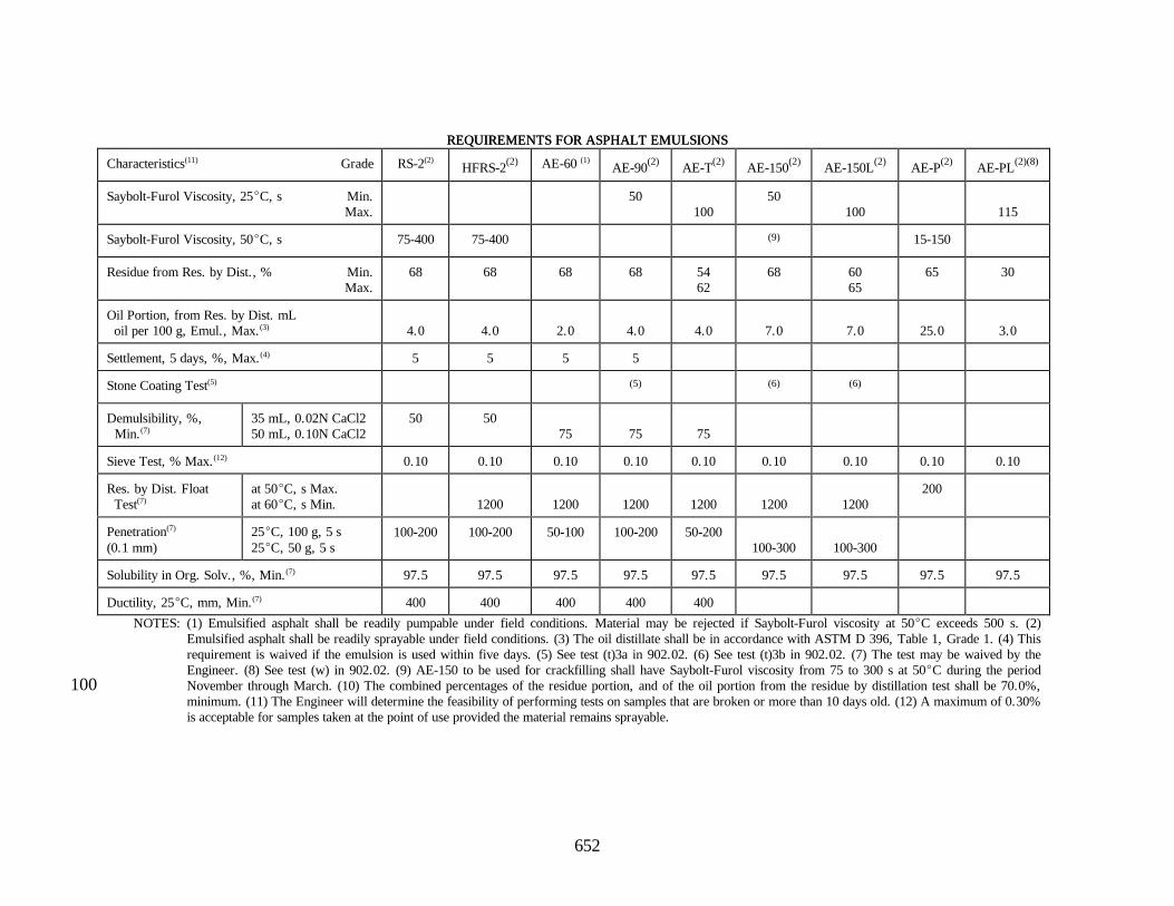
The requirements for asphalt emulsions shall be in accordance with thefollowing:
652
REQUIREMENTS FOR ASPHALT EMULSIONSREQUIREMENTS FOR ASPHALT EMULSIONS
NOTES: (1) Emulsified asphalt shall be readily pumpable under field conditions. Material may be rejected if Saybolt-Furol viscosity at 50EC exceeds 500 s. (2)Emulsified asphalt shall be readily sprayable under field conditions. (3) The oil distillate shall be in accordance with ASTM D 396, Table 1, Grade 1. (4) Thisrequirement is waived if the emulsion is used within five days. (5) See test (t)3a in 902.02. (6) See test (t)3b in 902.02. (7) The test may be waived by theEngineer. (8) See test (w) in 902.02. (9) AE-150 to be used for crackfilling shall have Saybolt-Furol viscosity from 75 to 300 s at 50EC during the periodNovember through March. (10) The combined percentages of the residue portion, and of the oil portion from the residue by distillation test shall be 70.0%,100minimum. (11) The Engineer will determine the feasibility of performing tests on samples that are broken or more than 10 days old. (12) A maximum of 0.30%is acceptable for samples taken at the point of use provided the material remains sprayable.
653
(c) Cutback (c) Cutback AsphaltsAsphalts.. Cutback asphalts shall be composed of an intimatehomogeneous mixture of an asphalt base and a suitable distillate designed for medium,or slow curing. Cutback asphalts may also contain an additive as an aid in uniformlycoating wet, damp, or dry aggregates used in patching mixtures or HMA pavements.These asphalts shall not contain more than 0.3% water as determined by AASHTO T55, shall not separate when allowed to stand, and shall not foam when heated topermissible temperatures. When an additive is used, it shall be incorporatedhomogeneously in the asphalt at the point of manufacture. The temperature of thecutback asphalt shall not be higher than shown for that grade in 902.03.
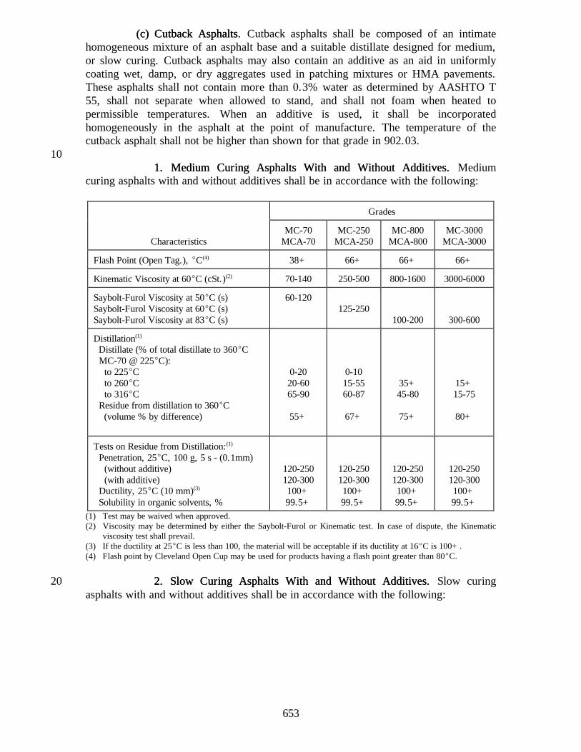
101. Medium Curing 1. Medium Curing Asphalts With and Without AdditivesAsphalts With and Without Additives.. Medium
curing asphalts with and without additives shall be in accordance with the following:
Grades
CharacteristicsMC-70
MCA-70MC-250
MCA-250MC-800
MCA-800MC-3000
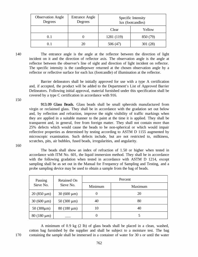
MCA-3000
Flash Point (Open Tag.), EC(4) 38+ 66+ 66+ 66+
Kinematic Viscosity at 60EC (cSt.)(2) 70-140 250-500 800-1600 3000-6000
Saybolt-Furol Viscosity at 50EC (s)Saybolt-Furol Viscosity at 60EC (s)Saybolt-Furol Viscosity at 83EC (s)
60-120125-250
100-200 300-600
Distillation(1)
Distillate (% of total distillate to 360EC MC-70 @ 225EC): to 225EC to 260EC to 316EC Residue from distillation to 360EC (volume % by difference)
(1) Test may be waived when approved.(2) Viscosity may be determined by either the Saybolt-Furol or Kinematic test. In case of dispute, the Kinematic
viscosity test shall prevail.(3) If the ductility at 25EC is less than 100, the material will be acceptable if its ductility at 16EC is 100+.(4) Flash point by Cleveland Open Cup may be used for products having a flash point greater than 80EC.
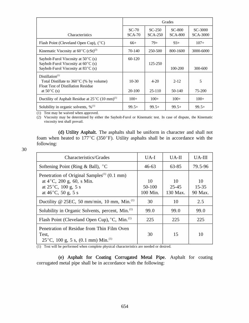
2. Slow Curing 2. Slow Curing Asphalts With and Without AdditivesAsphalts With and Without Additives.. Slow curing20asphalts with and without additives shall be in accordance with the following:
654
Grades
CharacteristicsSC-70
SCA-70SC-250
SCA-250SC-800
SCA-800SC-3000
SCA-3000
Flash Point (Cleveland Open Cup), (EC) 66+ 79+ 93+ 107+
Kinematic Viscosity at 60EC (cSt)(2) 70-140 250-500 800-1600 3000-6000
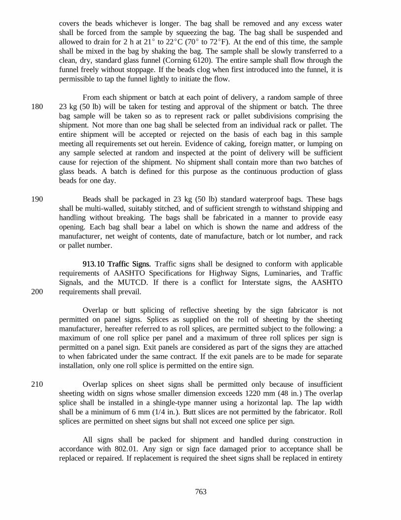
Saybolt-Furol Viscosity at 50EC (s)Saybolt-Furol Viscosity at 60EC (s)Saybolt-Furol Viscosity at 83EC (s)
60-120125-250
100-200 300-600
Distillation(1)
Total Distillate to 360EC (% by volume)Float Test of Distillation Residue at 50EC (s)
10-30
20-100
4-20
25-110
2-12
50-140
5
75-200
Ductility of Asphalt Residue at 25EC (10 mm)(1) 100+ 100+ 100+ 100+
Solubility in organic solvents, %(1) 99.5+ 99.5+ 99.5+ 99.5+(1) Test may be waived when approved.(2) Viscosity may be determined by either the Saybolt-Furol or Kinematic test. In case of dispute, the Kinematic
viscosity test shall prevail.
(d) Utility Asphalt(d) Utility Asphalt.. The asphalts shall be uniform in character and shall notfoam when heated to 177EC (350EF). Utility asphalts shall be in accordance with thefollowing:
30
Characteristics/Grades UA-I UA-II UA-III
Softening Point (Ring & Ball), EC 46-63 63-85 79.5-96
Penetration of Original Samples(1) (0.1 mm) at 4EC, 200 g, 60, s Min. at 25EC, 100 g, 5 s at 46EC, 50 g, 5 s
Solubility in Organic Solvents, percent, Min.(1) 99.0 99.0 99.0
Flash Point (Cleveland Open Cup),EC, Min.(1) 225 225 225
Penetration of Residue from Thin Film OvenTest, 25EC, 100 g, 5 s, (0.1 mm) Min.(1)
30 15 10
(1) Test will be performed when complete physical characteristics are needed or desired.
(e) Asphalt for Coating Corrugated Metal Pipe(e) Asphalt for Coating Corrugated Metal Pipe.. Asphalt for coatingcorrugated metal pipe shall be in accordance with the following:
655
Physical Properties Minimum Maximum
Softening Point (Ring & Ball), EC 93 110
Penetration of Original Samples (0.1 mm) at 4EC, 200 g, 60 s, Min. at 25EC, 100 g, 5 s
2035(1)
Solubility in Organic Solvents, % 99.0
Flash Point (Cleveland Open Cup), EC 232
Flow Test, mm 6.4
Shock Test 3 of 4 specimensshall pass
(1) May be 30 minimum provided all four shock test specimens pass.
902.02 Sampling and Testing Asphalt Materials902.02 Sampling and Testing Asphalt Materials.. The tests and AASHTOreference are as follows:
40(a) Sampling Bituminous Materials................................ AASHTO T 40
The following exceptions to AASHTO T 40 shall apply:
1. Samples may be obtained at any time before material is incorporatedinto the work.
2. Samples for all grades of asphalt emulsion shall be a minimum of1.9 L (1/2 gal.). The size of samples of other liquid material may be1.0 L (1 qt).
503. Samples of liquid materials shall be obtained as follows:
a. bulk storage tanks from approved sampling valves located in thetank or line and asphalt plant storage tanks from approvedsampling valves located in the tank
b. transports from approved sampling valves
c. distributors from approved sampling valves60
d. other storage or locations as approved
e. sampling by other recognized devices may be approved
(b) Water in petroleum products, except the solventor carrier may be toluene.......................................AASHTO T 55
(c) Density, Specific Gravity, or API Gravity ofCrude Petroleum and Liquid Products byHydrometer Method........................................... AASHTO T 22770
656
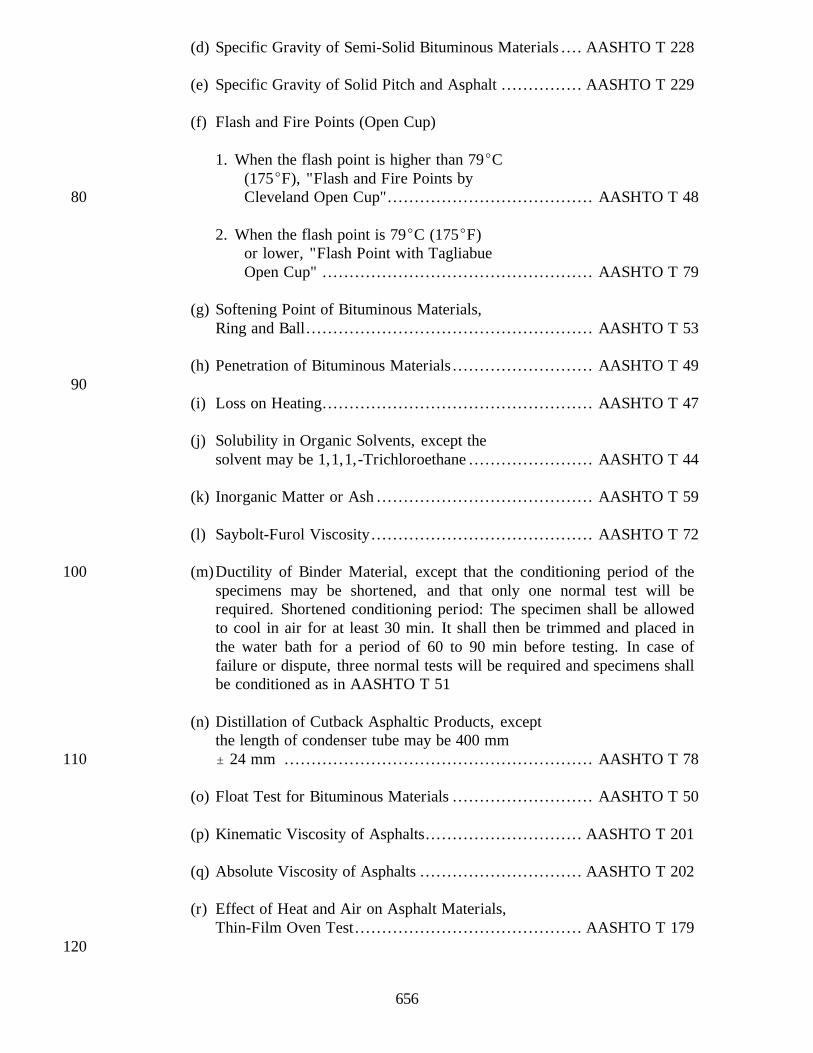
(d) Specific Gravity of Semi-Solid Bituminous Materials .... AASHTO T 228
(e) Specific Gravity of Solid Pitch and Asphalt ............... AASHTO T 229
(f) Flash and Fire Points (Open Cup)
1. When the flash point is higher than 79EC(175EF), "Flash and Fire Points byCleveland Open Cup"...................................... AASHTO T 4880
2. When the flash point is 79EC (175EF)or lower, "Flash Point with TagliabueOpen Cup" .................................................. AASHTO T 79
(g) Softening Point of Bituminous Materials,Ring and Ball..................................................... AASHTO T 53
(h) Penetration of Bituminous Materials .......................... AASHTO T 4990
(i) Loss on Heating.................................................. AASHTO T 47
(j) Solubility in Organic Solvents, except thesolvent may be 1,1,1,-Trichloroethane ....................... AASHTO T 44
(k) Inorganic Matter or Ash ........................................ AASHTO T 59
(l) Saybolt-Furol Viscosity......................................... AASHTO T 72
(m)Ductility of Binder Material, except that the conditioning period of the100specimens may be shortened, and that only one normal test will berequired. Shortened conditioning period: The specimen shall be allowedto cool in air for at least 30 min. It shall then be trimmed and placed inthe water bath for a period of 60 to 90 min before testing. In case offailure or dispute, three normal tests will be required and specimens shallbe conditioned as in AASHTO T 51
(n) Distillation of Cutback Asphaltic Products, exceptthe length of condenser tube may be 400 mm" 24 mm ......................................................... AASHTO T 78110
(o) Float Test for Bituminous Materials .......................... AASHTO T 50
(p) Kinematic Viscosity of Asphalts............................. AASHTO T 201
(q) Absolute Viscosity of Asphalts .............................. AASHTO T 202
(r) Effect of Heat and Air on Asphalt Materials,Thin-Film Oven Test.......................................... AASHTO T 179
120
657
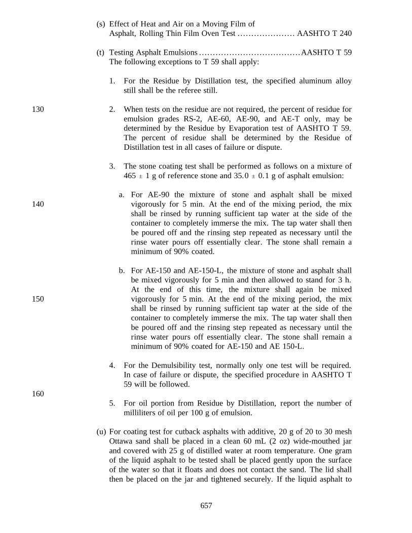
(s) Effect of Heat and Air on a Moving Film ofAsphalt, Rolling Thin Film Oven Test ..................... AASHTO T 240
(t) Testing Asphalt Emulsions .....................................AASHTO T 59The following exceptions to T 59 shall apply:
1. For the Residue by Distillation test, the specified aluminum alloystill shall be the referee still.
2. When tests on the residue are not required, the percent of residue for130emulsion grades RS-2, AE-60, AE-90, and AE-T only, may bedetermined by the Residue by Evaporation test of AASHTO T 59.The percent of residue shall be determined by the Residue ofDistillation test in all cases of failure or dispute.
3. The stone coating test shall be performed as follows on a mixture of465 " 1 g of reference stone and 35.0 " 0.1 g of asphalt emulsion:
a. For AE-90 the mixture of stone and asphalt shall be mixedvigorously for 5 min. At the end of the mixing period, the mix140shall be rinsed by running sufficient tap water at the side of thecontainer to completely immerse the mix. The tap water shall thenbe poured off and the rinsing step repeated as necessary until therinse water pours off essentially clear. The stone shall remain aminimum of 90% coated.
b. For AE-150 and AE-150-L, the mixture of stone and asphalt shallbe mixed vigorously for 5 min and then allowed to stand for 3 h.At the end of this time, the mixture shall again be mixedvigorously for 5 min. At the end of the mixing period, the mix150shall be rinsed by running sufficient tap water at the side of thecontainer to completely immerse the mix. The tap water shall thenbe poured off and the rinsing step repeated as necessary until therinse water pours off essentially clear. The stone shall remain aminimum of 90% coated for AE-150 and AE 150-L.
4. For the Demulsibility test, normally only one test will be required.In case of failure or dispute, the specified procedure in AASHTO T59 will be followed.
1605. For oil portion from Residue by Distillation, report the number of
milliliters of oil per 100 g of emulsion.
(u) For coating test for cutback asphalts with additive, 20 g of 20 to 30 meshOttawa sand shall be placed in a clean 60 mL (2 oz) wide-mouthed jarand covered with 25 g of distilled water at room temperature. One gramof the liquid asphalt to be tested shall be placed gently upon the surfaceof the water so that it floats and does not contact the sand. The lid shallthen be placed on the jar and tightened securely. If the liquid asphalt to
658
be tested is grade 70 or 250, the jar and contents shall be shaken170vigorously for 30 s. If the grade is 800 or 3000, the jar and contentsshall be immersed in a 46EC (115EF) water bath for 5 min to bring thecontents of the jar to a temperature of approximately 38EC (100EF). Thejar shall then be shaken vigorously for 30 s. After shaking, the asphaltcoating on the sand shall be observed under a constant, strong light.Complete coating of the sand is required.
(v) Stripping tests for HMA mixtures using binder materials, with or withoutadditives, shall be performed as follows:
1801. Test 1.1. Test 1. A sample of produced mixture, 500 g, minimum, shall beobtained for testing. The size of test specimen and the amount of distilledwater shall be:
Approximate Minimum Amount ofSize of Weight of DistilledAggregate Test Specimen Water
Sand 100 g 400 mL12 100 g 400 mL19011 150 g 600 mL9 200 g 600 mL
Place the specimen in the boiling distilled water and stir with a glass rodat the rate of one revolution per second for 3 min. The aggregate shallretain a minimum of 90% of its asphalt film compared with theremainder of the sample, upon completion of this procedure.
2. Test 2.2. Test 2. Approximately 500 g of produced mixture shall be heated to121EC (250EF) in a laboratory oven for 2 h; stirred and cooled to20092.5EC (200EF). Then a portion of the mix shall be placed in boilingdistilled water, quantity of mix and quantity of boiling water shall be asspecified in Test 1, and stirred with a glass rod at the rate of onerevolution per second for 3 min. The aggregate shall retain a minimumof 90% of its asphalt film compared with the remainder of the sample,upon completion of this procedure.
Note: The purpose of these tests is to determine the relative compatibility of the aggregateand asphalt, and to detect tendency of Asphalt Emulsions to reemulsify. Test 2 maybe performed as a method of determining whether compatibility can be achieved,210Test 1 having given unsatisfactory results.
(w) Penetrating Ability of AE-PL.
1. Apparatus and Equipment:
a.Sand mixture:
(1) Dry Standard Ottawa Sand (AASHTO T 106) .......... 90 parts220
659
(2) Dry Reference Limestone Dust, portion passing 300 mm (#50)sieve only. Reference Limestone Dust used by the Departmentis Limestone Calcium Carbonate manufactured by FranceStone Co. The Department will furnish approximately 2.3 kg(5 lb) of Reference Limestone Dust upon request...... 10 parts
(3) Water............................................................ 3 parts
b. Container, 170 g (6 oz) ointment tin230
c. Ruler or other measuring device
d. Timing device readable in seconds
e. Compacting Device. Rimac Spring Tester or other device suitablefor compacting sand by applying a 140 kPa (20 psi) load. Thecompacting device shall include an adapter consisting of two metaldiscs slightly smaller in diameter than a 170 g (6 oz) ointment tinseparated by a spacer 25 to 50 mm (1 to 2 in.). The 65 mm(2.5 in.) diameter discs used in determining weight of coating in240AASHTO T 65 or ASTM A 90 are satisfactory.
f. Small, square ended spatula or putty knife
2. Procedure:
Thoroughly mix Standard Ottawa Sand, Reference Limestone Dust,and water. Weigh 190 " 1 g of sand mixture into a 170 g (6 oz)ointment tin. Level surface of sand with a spatula. Place thecompacting adapter on the sand surface and slowly, over a period of250about 5 s, compact the sand until the 140 kPa (20 psi) load isachieved, which is approximately 45 kg (100 lb) on the RimacSpring Tester. Remove the compacting device, avoiding disturbanceto the sand surface. Quickly pour 12 g of the emulsion from a heightof about 100 mm (4 in.) onto top of sand mixture. Start timer at startof pour. Stop timer when all emulsion penetrates into sand mixture.Delay 2 min, then remove sand and mixture from one side ofointment tin, about 1/2 of mixture. Measure to determine averagedepth of penetration into sand mixture. Penetration time shall be 100s or less; penetration depth shall be 6 mm (1/4 in.) or more.260
(x) Flow Test for Asphalt for Coating CorrugatedMetal Pipe ..................................................... AASHTO M 190
(y) Shock Test for Asphalt for Coating CorrugatedMetal Pipe ..................................................... AASHTO M 190
(z) Viscosity Determinations of Unfilled AsphaltsUsing the Brookfield Thermosel Apparatus................AASHTO TP 48
270
660
(aa) Determining the Rheological Properties of AsphaltBinder Using a Dynamic Shear Rheometer............... AASHTO TP 5
(bb) Accelerated Aging of Asphalt Binder Using aPressurized Aging Vessel ....................................AASHTO PP 1
(cc) Determining the Flexural Creep Stiffness ofAsphalt Binder Using the Bending Beam Rheometer ... AASHTO TP 1
902.03 Application Temperatures902.03 Application Temperatures. . Binder materials for the several applications280indicated in the specifications shall be applied at temperatures not to exceed thoseshown in the following:
Maximum ApplicationType and Grade of Material Temperature EC (EF)
Note (1): In accordance with manufacturer's recommendations.
SECTION 903 -- CLASSIFICATION OF SOILSSECTION 903 -- CLASSIFICATION OF SOILS
903.01 Definitions903.01 Definitions.. All of the soils shall be tested and classified in accordancewith AASHTO M 145, and in accordance with the grain-size classification procedure asfollows:
Soil Classification Definition
Boulders Retained on 75 mm (3 in) sieve
Gravel 75 mm (3 in) to 2.0 mm (No. 10) sieve
Coarse Sand 2.00 mm (No. 10) to 425 :m (No. 40) sieve
Fine Sand 425 :m (No. 40) to 75 :m (No. 200) sieve
Silt 0.075 to 0.002 mm
Clay Smaller than 0.002 mm
Colloids Smaller than 0.001 mm
661
903.02 Soils Having 0% to 19% Retained on 2.00 mm (No. 10) Sieve903.02 Soils Having 0% to 19% Retained on 2.00 mm (No. 10) Sieve.. Thesesoils shall be classified as follows:
10
ClassificationPercent
Sand and Gravel Percent Silt Percent Clay
Sand 80 - 100 0 - 20 0 - 20
Sandy Loam 50 - 80 0 - 50 0 - 20
Loam 30 - 50 30 - 50 0 - 20
Silty Loam 0 - 50 50 - 80 0 - 20
Silt 0 - 20 80 - 100 0 - 20
Sandy Clay Loam 50 - 80 0 - 30 20 - 30
Clay Loam 20 - 50 20 - 50 20 - 30
Silty Clay Loam 0 - 30 50 - 80 20 - 30
Sandy Clay 50 - 70 0 - 20 30 - 50
Silty Clay 0 - 20 50 - 70 30 - 50
Clay 0 - 50 0 - 50 30 - 100
903.03 Soils Having 20% or More Retained on 2.00 mm (No. 10) Sieve and903.03 Soils Having 20% or More Retained on 2.00 mm (No. 10) Sieve andMore Than 20% Passing 75 More Than 20% Passing 75 FFm (No. 200) Sievem (No. 200) Sieve.. These soils shall be classified inaccordance with 903.02, followed by a term describing the relative amount of gravel asfollows:
20% to 35%: "with some gravel"36% to 50%: "and gravel"
903.04 Soils Having 20% or More Retained on 2.903.04 Soils Having 20% or More Retained on 2.00 mm (No. 10) Sieve and00 mm (No. 10) Sieve and20Less Than 20% Passing 75 Less Than 20% Passing 75 FFm (No. 200) Sievem (No. 200) Sieve.. These soils shall be classified asfollows:
ClassificationPercentGravel
PercentSand
PercentSilt
PercentClay
Gravel 85 - 100 0 - 15 0 - 15 0 - 15
Sandy Gravel 40 - 85 15 - 40 0 - 20 0 - 20
Gravelly Sand 20 - 40 40 - 80 0 - 20 0 - 20
Sand & Gravel 20 - 50 20 - 50 0 - 20 0 - 20
If the gradation of a given sample is not in exact accordance with therequirements for a given classification, it shall be placed in the classification to which itcomes the closest.
662
903.05 Organic Soils903.05 Organic Soils.. The following classification system shall be used fororganic soils in accordance with AASHTO T 267.30
Classification Percentage
With Trace Organic Matter 1 to 6
With Little Organic Matter 7 to 12
With Some Organic Matter 13 to 18
Organic Soil (A-8) 19 - 30
Peat (A-8) More than 30
903.06 903.06 Marly SoilsMarly Soils.. The following classification system shall be used for marlysoils with calcium and magnesium carbonate content.
904.01 Fine Aggregates904.01 Fine Aggregates.. Fine aggregates shall consist of natural sand ormanufactured sand produced by crushing limestone, dolomite, steel furnace (SF) slag,air cooled blast furnace (BF) slag, granulated blast furnace (GBF), or wet bottom boilerslag. Natural sand, which has been used as foundry sand, may be used in precastconcrete units and precast concrete pipe. At time of use fine aggregate shall be freefrom lumps or crusts of hardened or frozen materials and shall be in accordance withthe specifications as set out herein.
10No source will be considered for acceptance of material until a preliminary
investigation has been made. As part of this investigation, samples will be taken andtests conducted to determine the quality of the aggregates.
Fine aggregates, except for fine aggregates used for snow and ice abrasive orprecast concrete units, shall be supplied by a Certified Aggregate Producer inaccordance with 917.
(a) For Portland Cement Concrete(a) For Portland Cement Concrete.. Fine aggregate for use in portlandcement concrete pavement or bridge decks shall be natural sand. Fine aggregate for20other portland cement concrete shall be natural sand or crushed limestone, dolomite, or
663
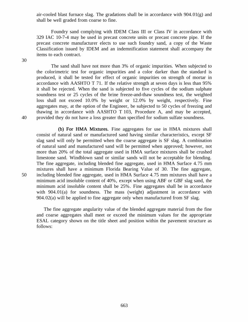
air-cooled blast furnace slag. The gradations shall be in accordance with 904.01(g) andshall be well graded from coarse to fine.
Foundry sand complying with IDEM Class III or Class IV in accordance with329 IAC 10-7-4 may be used in precast concrete units or precast concrete pipe. If theprecast concrete manufacturer elects to use such foundry sand, a copy of the WasteClassification issued by IDEM and an indemnification statement shall accompany theitems to each contract.
30The sand shall have not more than 3% of organic impurities. When subjected to
the colorimetric test for organic impurities and a color darker than the standard isproduced, it shall be tested for effect of organic impurities on strength of mortar inaccordance with AASHTO T 71. If the relative strength at seven days is less than 95%it shall be rejected. When the sand is subjected to five cycles of the sodium sulphatesoundness test or 25 cycles of the brine freeze-and-thaw soundness test, the weightedloss shall not exceed 10.0% by weight or 12.0% by weight, respectively. Fineaggregates may, at the option of the Engineer, be subjected to 50 cycles of freezing andthawing in accordance with AASHTO T 103, Procedure A, and may be accepted,provided they do not have a loss greater than specified for sodium sulfate soundness.40
(b) For HMA Mixtures(b) For HMA Mixtures. . Fine aggregates for use in HMA mixtures shallconsist of natural sand or manufactured sand having similar characteristics, except SFslag sand will only be permitted when the coarse aggregate is SF slag. A combinationof natural sand and manufactured sand will be permitted when approved; however, notmore than 20% of the total aggregate used in HMA surface mixtures shall be crushedlimestone sand. Windblown sand or similar sands will not be acceptable for blending.The fine aggregate, including blended fine aggregate, used in HMA Surface 4.75 mmmixtures shall have a minimum Florida Bearing Value of 30. The fine aggregate,including blended fine aggregate, used in HMA Surface 4.75 mm mixtures shall have a50minimum acid insoluble content of 40%, except when using ABF or GBF slag sand, theminimum acid insoluble content shall be 25%. Fine aggregates shall be in accordancewith 904.01(a) for soundness. The mass (weight) adjustment in accordance with904.02(a) will be applied to fine aggregate only when manufactured from SF slag.
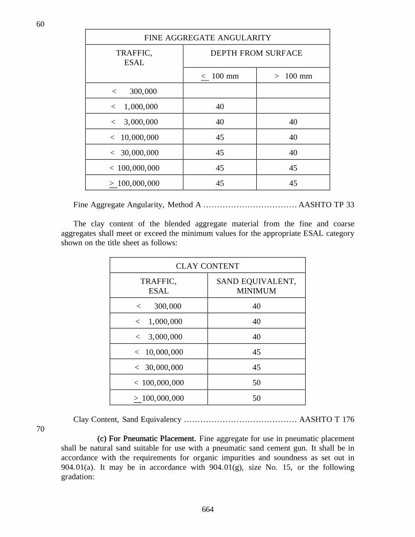
The fine aggregate angularity value of the blended aggregate material from the fineand coarse aggregates shall meet or exceed the minimum values for the appropriateESAL category shown on the title sheet and position within the pavement structure asfollows:
664
60
FINE AGGREGATE ANGULARITY
TRAFFIC,ESAL
DEPTH FROM SURFACE
< 100 mm > 100 mm
< 300,000
< 1,000,000 40
< 3,000,000 40 40
< 10,000,000 45 40
< 30,000,000 45 40
<100,000,000 45 45
>100,000,000 45 45
Fine Aggregate Angularity, Method A ..................................AASHTO TP 33
The clay content of the blended aggregate material from the fine and coarseaggregates shall meet or exceed the minimum values for the appropriate ESAL categoryshown on the title sheet as follows:
CLAY CONTENT
TRAFFIC,ESAL
SAND EQUIVALENT,MINIMUM
< 300,000 40
< 1,000,000 40
< 3,000,000 40
< 10,000,000 45
< 30,000,000 45
<100,000,000 50
>100,000,000 50
Clay Content, Sand Equivalency ......................................... AASHTO T 17670
(c) For Pneumatic Placement(c) For Pneumatic Placement. . Fine aggregate for use in pneumatic placementshall be natural sand suitable for use with a pneumatic sand cement gun. It shall be inaccordance with the requirements for organic impurities and soundness as set out in904.01(a). It may be in accordance with 904.01(g), size No. 15, or the followinggradation:
665
Sieve Size No.4.75 mm
(4)2.36 :m
(8)600 :m
(30)300 :m
(50)150 :m(100)
Percent Passing 100 85-95 50-65 15-25 0-10
(d) For Mortar(d) For Mortar. . Fine aggregate for mortar shall consist of natural sand. Itshall be graded uniformly from coarse to fine and shall be in accordance with gradationrequirements of 904.01(g) for size No. 15. It shall be in accordance with 904.01(a) for80organic impurities and soundness.
(e) Mineral Filler(e) Mineral Filler. . Mineral filler shall consist of dust produced by crushingstone, portland cement, fly ash, or other inert mineral matter having similarcharacteristics for use in HMA. It shall be in accordance with the gradationrequirements of 904.01(g) for size No. 16. Fly ash shall have been collected by meansof an electrostatic precipitation method and shall not contain free carbon in excess of10% by mass (weight). The sieve analysis of mineral filler shall be conducted inaccordance with AASHTO T 37 except as noted in 904.03.
90(f) Snow and Ice Abrasives(f) Snow and Ice Abrasives. . Snow and ice abrasives shall be steel furnace
slag, air cooled blast furnace slag, granulated blast furnace slag, boiler slag, naturalsand, crushed stone sand, or cinders. The abrasives shall pass the following gradationrequirements:
Passing the 9.5 mm (3/8 in.) sieve ........................................... 100%Passing the 300 Fm (No. 50) sieve .......................................... 0-30%Passing the 75 Fm (No. 200) sieve ............................................0-7%
When steel slag is used as snow and ice abrasives, and payment is on a tonnage100basis, the pay quantity shall be adjusted in accordance with 904.02(a).
666
(g) Sizes(g) Sizes of Fine Aggregates of Fine Aggregates..
SIZES (PERCENTS PASSING)SieveSizes 23 24 15 16
9.5 mm (3/8 in.) 100 100
4.75 mm (No. 4) 95-100 95-100
3.35 mm (No. 6) 100
2.36 mm (No. 8) 80-100 70-100 90-100
1.18 mm (No. 16) 50-85 40-80
600 :m (No. 30) 25-60 20-60 50-75 100
300 :m (No. 50) 5-30 7-40 15-40
180 :m (No. 80) 95-100
150 :m (No. 100) 0-10 1-20 0-10
75 :m (No. 200) 0-3 0-6 0-3 65-100Note: The fine aggregate shall have not more than 45% retained between any 2 consecutive sieves.
(h) Sampling and Testing(h) Sampling and Testing. . Sampling and testing shall be conducted inaccordance with the following AASHTO and ITMs:
Acid Insoluble Content .................................................... ITM 202*Amount of Material Finer than110
75 Fm (No. 200) sieve..........................................AASHTO T 11Brine Freeze-and-Thaw Soundness ....................................... ITM 209 Control Procedures for Classification of Aggregates.................. ITM 203 Florida Bearing Value ..................................................... ITM 201 Mortar Strength......................................................AASHTO T 71 Organic Impurities ..................................................AASHTO T 21*Sampling Aggregates ................................................ AASHTO T 2 Sampling Stockpiled Aggregates ......................................... ITM 207*Sieve Analysis of Aggregate ......................................AASHTO T 27*Sieve Analysis of Mineral Filler..................................AASHTO T 37120*Soundness ................................................. AASHTO T 103, T 104
(a) General Requirements(a) General Requirements. . Coarse aggregates shall consist of crushedlimestone or dolomite; crushed or uncrushed gravel; crushed steel furnace (SF) slag orair cooled blast furnace (BF) slag; or sandstone. When dolomite coarse aggregates areused in accordance with 401.03 or 402.02, the material furnished shall be carbonaterock containing at least 10.3% elemental magnesium when tested as set out in ITM130205. Coarse aggregates shall not contain more than 10% flat and elongated pieces andshall not contain particles with an adherent coating. A flat and elongated piece isdefined as a particle having a ratio of length to thickness greater than five.
667
Sandstone may be used only in HMA surface mixtures. Sandstone for this useshall be in accordance with the Class B quality requirements. Sandstone is defined as asedimentary rock composed of siliceous sandgrains containing quartz, chert, andquartzose rock fragments in a carbonate matrix or cemented with silica, calcite, ordolomite. Identification of a sandstone will be determined by the Materials and TestsDivision.140
Steel furnace (SF) slag may be used in compacted aggregate shoulders inaccordance with 303, in surface mixtures with Asphalt Emulsion in accordance with402, in HMA surface mixtures in accordance with 402, as dumped riprap in accordancewith 904.04(a), and for snow and ice abrasives in accordance with 904.01(f).
When slag is furnished as an alternate to natural aggregate, and payment is on amass (weight) basis, adjustments shall be made to compensate for the difference inspecific gravity of the slag compared to natural aggregate. The following typical valuesfor specific gravity will be used: natural aggregate both fine and coarse, 2.6; air cooled150blast furnace (ABF) slag coarse aggregate, 2.3; air cooled blast furnace (ABF) slag fineaggregate, 2.6; granulated blast furnace (GBF) slag fine aggregate, 2.1; and steelfurnace (SF) slag both fine and coarse, 3.2. The adjustment shall not apply toaggregates or HMA mixture used for approaches or patching.
When slag is furnished as an ingredient of a HMA mixture, the adjustment shallbe applied as follows:
1. Determine the amount of natural aggregate in the mixture using thefollowing formula:160
A = T(1-%B)A = Megagrams (tons) of natural aggregate in the mixture.T = Pay item quantity in megagrams (tons) for the specified
mixture.%B = Percent bitumen as decimal from the job mix formula.%FA = Percent passing 4.75 mm (No. 4) sieve as a decimal from
the JMF.%CA = Percent retained on 4.75 mm (No. 4) sieve as a decimal
from the JMF.170
2. Determine the amount of slag required for coarse aggregate (CAS)by the following formula:
CAS = A(%CA) (SpGr Slag/2.6)
3. Determine the amount of slag required for fine aggregate (FAS) bythe following formula:
FAS = A(%FA) (SpGr Slag/2.6)180
4. Determine the adjusted quantity in megagrams (tons) (TAS) by thefollowing formula:
668
TAS = T(%B) + CAS + Weight of fine aggregate used
5. Adjust the design lay in kilograms per square meter (lb per sq yd) bythe following formula:
Adjusted lay = (Design Lay) (TAS/T)190
6. Determine adjusted pay quantity by the following formula:
When slag is furnished as an aggregate, the approximate quantity of megagrams(tons) to be supplied will be determined by multiplying the pay item quantity ofmegagrams (tons) by the specific gravity of slag divided by 2.6. The adjusted payquantities will be determined by multiplying the accepted quantity of megagrams (tons)by 2.6 divided by the specific gravity of the slag.200
Crushed gravel shall have a minimum of one angular fractured face, such as abroken surface, which was caused mechanically or naturally. Natural fractures andmechanical fractures shall be the same in texture and effect. An acceptable fracturedarea shall have at least 25% of the largest cross sectional area of the particle asspecified in ITM 204.
Recycled portland cement concrete may be used in compacted aggregate base inaccordance with 303. Recycled portland cement concrete shall be in accordance withquality and gradation requirements. If recycled portland cement concrete pavement is210used from within the project limits, only the gradation requirements will apply.
No source will be considered for acceptance of material until a preliminaryinvestigation has been made. As part of this investigation, samples will be obtained andtests conducted to determine the classification of the aggregates. There are two types ofsamples required for the preliminary investigation; namely, ledge samples for crushedstone sources and production samples for crushed stone, gravel, and slag sources.
Ledge samples will be obtained from the bedrock units as they naturally occur inthe proposed working face of the quarry. These units will be identified by their220differences in color, texture, geological formation, etc.
Production samples will be obtained from stockpiles of finished materials.
The coarse aggregate shall comply with the quality requirements and theadditional requirements as shown in the following table. However, coarse aggregatemay be rejected based on previous performance service records. Class A is defined asthe highest classification and class F the lowest. Blending of material for compliancewith gradation or crushed particle requirements may be permitted when requested inwriting. Blending a material which does not meet the quality or deleterious230requirements with a better material to upgrade the end product will not be permitted.
669
Classification of finished products offered for use will be made in accordancewith ITM 203.
Coarse aggregates, except for coarse aggregates used for precast concrete units,shall be supplied by a Certified Aggregate Producer in accordance with 917.
(b) Classification of Aggregates(b) Classification of Aggregates..Characteristic Classes AP A B C D E F
Additional Requirements Deleterious, %, Max. Clay Lumps and Friable Particles............. Non-Durable (Note 4).......................... Coke ............................................. Iron .............................................. Chert (Note 5) .................................. Mass Per Cubic Meter for Slag, kg, Weight Per Cubic Foot for Slag, (lbs), Min.............................................
0.24.0
3.01200
(75.0)
0.24.0
3.01200
(75.0)
0.24.0
5.01200
(75.0)
0.26.0(See(See8.0
1120
0.28.0
Note 7)Note 7)
10.01120
(70.0)
1120
(70.0)
Crushed Particles, %, Min. (Note 6) Asphalt Seal Coats Compacted Aggregates
70.020.0
70.020.0 20.0 20.0
NOTES: 1. Los Angeles abrasion requirements shall not apply to blast furnace slag.2402. Aggregates may, at the option of the Engineer, be subjected to 50 cycles of freezing and thawing in
accordance with AASHTO T 103, Procedure A, and may be accepted, provided they do not have a lossgreater than specified for Sodium Sulfate Soundness.
3. Absorption requirements apply only to aggregates used in portland cement concrete and HMA mixturesexcept they shall not apply to blast furnace slag. When crushed stone coarse aggregates from Category Isources consist of production from ledges whose absorptions differ by more than two percentage points,the absorption test will be performed every three months on each size of material proposed for use inportland cement concrete or HMA mixtures. Materials having absorption values between 5.0 and 6.0 thatpass AP testing may be used in portland cement concrete. If variations in absorption preclude satisfactoryproduction of portland cement concrete or HMA mixtures, independent stockpiles of materials will be250sampled, tested, and approved prior to use.
4. Non-durable particles include soft particles as determined by ITM 206 and other particles which arestructurally weak, such as soft sandstone, shale, limonite concretions, coal, weathered schist, cementedgravel, ocher, shells, wood, or other objectionable material. Determination of non-durable particles shallbe made from the total mass (weight) of material retained on the 9.5 mm (3/8 in.) sieve. ScratchHardness Test shall not apply to crushed stone coarse aggregate.
5. The bulk specific gravity of chert shall be based on the saturated surface dry condition. The amount ofchert less than 2.45 bulk specific gravity, shall be determined on the total mass (weight) of materialretained on the 9.5 mm (3/8 in.) sieve for sizes 1 through 8, 53, and 91 and on the total mass (weight) ofmaterial retained on the 4.75 mm (No. 4) sieve for sizes 9 and 11.260
6. Crushed particle requirements will apply to gravel coarse aggregates used in HMA mixtures, compactedaggregates, and asphalt seal coats except seal coats used on shoulders. Crushed particle requirements forHMA mixtures are set out in 904.02(c). Determination of crushed particles shall be made in accordancewith ASTM D 5821.
7. Air-cooled blast furnace slag and steel slag coarse aggregate shall be free of objectionable amounts ofcoke and iron.
8. Brine freeze-and-thaw soundness requirements are subject to the conditions stated in note 2.9. Freeze-and-thaw beam expansion shall be tested and retested in accordance with ITM 210.
670
(c) Coarse Aggregate Angularity(c) Coarse Aggregate Angularity.. The coarse aggregate shall not contain flat270and elongated particles exceeding the maximum value for the appropriate ESALcategory shown on the title sheet as follows:
FLAT AND ELONGATED PARTICLES
TRAFFIC,ESAL
PERCENT,MAXIMUM
< 300,000
< 1,000,000
< 3,000,000 10
< 10,000,000 10
< 30,000,000 10
<100,000,000 10
>100,000,000 10
Flat and Elongated Particles ........................................ ASTM D 4791
The angularity value of the coarse aggregate shall meet or exceed the minimumvalues for the appropriate ESAL category shown on the title sheet and position withinthe pavement structure as follows:
280
COARSE AGGREGATE ANGULARITY
DEPTH FROM SURFACETRAFFIC,ESAL < 100 mm > 100 mm
< 300,000 55
< 1,000,000 65
< 3,000,000 75 50
< 10,000,000 85/80* 60
< 30,000,000 95/90* 80/75*
<100,000,000 100/100* 95/90*
>100,000,000 00/100* 100/100** Denotes two faced crush requirements
Coarse Aggregate Angularity ........................................... ASTM D 5821
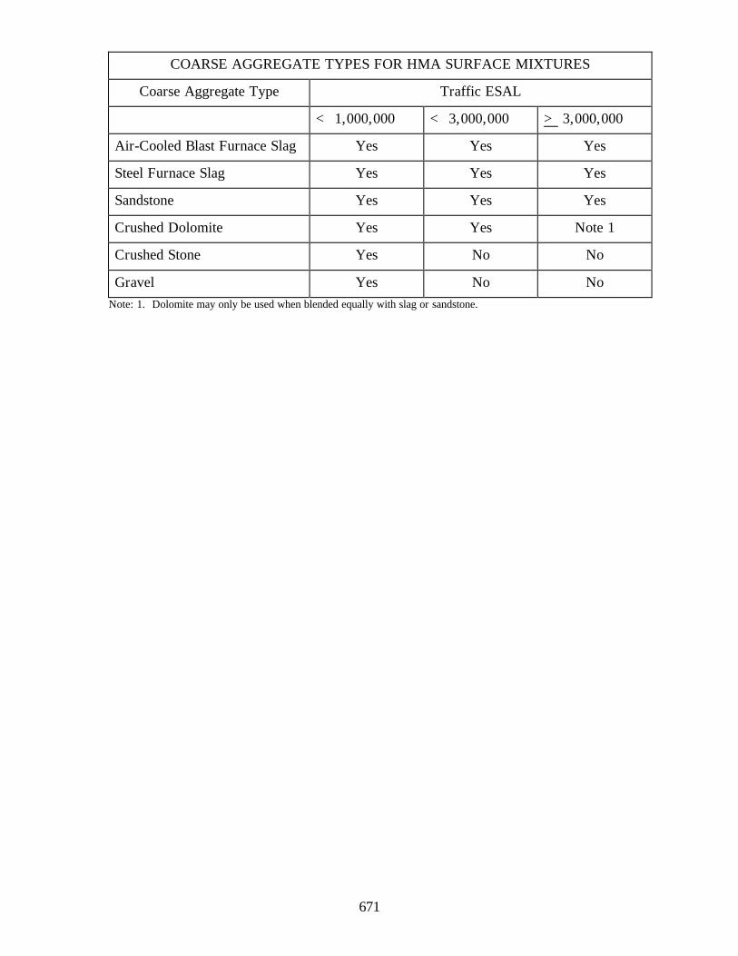
(d) Surface Aggregate Requirements(d) Surface Aggregate Requirements.. The surface aggregate selection shallbe based on the ESAL loadings for the project as following:
671
COARSE AGGREGATE TYPES FOR HMA SURFACE MIXTURES
Coarse Aggregate Type Traffic ESAL
< 1,000,000 < 3,000,000 > 3,000,000
Air-Cooled Blast Furnace Slag Yes Yes Yes
Steel Furnace Slag Yes Yes Yes
Sandstone Yes Yes Yes
Crushed Dolomite Yes Yes Note 1
Crushed Stone Yes No No
Gravel Yes No NoNote: 1. Dolomite may only be used when blended equally with slag or sandstone.
672
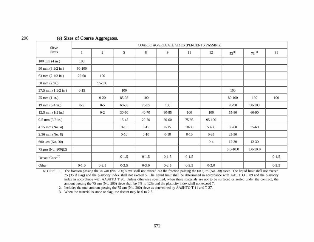
(e) Sizes(e) Sizes of Coarse Aggregates of Coarse Aggregates..290COARSE AGGREGATE SIZES (PERCENTS PASSING)
Other 0-1.0 0-2.5 0-2.5 0-3.0 0-2.5 0-2.5 0-2.0 0-2.5
NOTES: 1. The fraction passing the 75 Fm (No. 200) sieve shall not exceed 2/3 the fraction passing the 600 Fm (No. 30) sieve. The liquid limit shall not exceed25 (35 if slag) and the plasticity index shall not exceed 5. The liquid limit shall be determined in accordance with AASHTO T 89 and the plasticityindex in accordance with AASHTO T 90. Unless otherwise specified, when these materials are not to be surfaced or sealed under the contract, theamount passing the 75 Fm (No. 200) sieve shall be 5% to 12% and the plasticity index shall not exceed 7.
2. Includes the total amount passing the 75 Fm (No. 200) sieve as determined by AASHTO T 11 and T 27.3. When the material is stone or slag, the decant may be 0 to 2.5.
673
(f) Sampling and Testing(f) Sampling and Testing.. Sampling and testing shall be in accordance withthe following AASHTO and ITMs:
300 Abrasion ..............................................................AASHTO T 96*Amount of Material finer than No. 200 (75 Fm) Sieve ..........................................AASHTO T 11 Brine Freeze-and-Thaw Soundness ...................................... ITM 209 Clay Lumps and Friable Particles............................... AASHTO T 112 Control Procedures for Classification of Aggregates.................. ITM 203 Crushed Particles ........................................................... ITM 204 Dolomite Aggregates....................................................... ITM 205 Freeze-and-Thaw Beam Expansion ...................................... ITM 210*Lightweight Pieces in Aggregates .............................. AASHTO T 113310*Sampling Aggregates ................................................ AASHTO T 2 Sampling Stockpiled Aggregates ......................................... ITM 207 Scratch Hardness ........................................................... ITM 206*Sieve Analysis.......................................................AASHTO T 27*Soundness ................................................. AASHTO T 103, T 104*Specific Gravity and Absorption..................................AASHTO T 85 Unit Weight and Voids in Aggregates............................AASHTO T 19
*Except as noted in 904.03.
904.03 Excepti904.03 Exceptions to AASHTO Standard Methodsons to AASHTO Standard Methods..320
(a) Exceptions to AASHTO T 2(a) Exceptions to AASHTO T 2. . Stockpile sampling shall be done inaccordance with ITM 207, unless otherwise permitted.
(b) Exceptions to AASHTO T 11, T 27, and T 37(b) Exceptions to AASHTO T 11, T 27, and T 37..
1. When tests are performed in the field where ovens are not available,test samples may be dried in suitable containers over open flame orelectric hot plates with sufficient stirring to prevent overheating,then cooled to constant mass (weight).330
2. The scales used for performing field tests of fine aggregates shall begraduated in increments not greater than one gram.
(c) Exceptions to AASHTO T 27 for Coarse Aggregates(c) Exceptions to AASHTO T 27 for Coarse Aggregates..
1. The size of test samples for coarse aggregate shall be as follows:
Aggregate SizeAggregate Size Minimum Mass (Weight)Minimum Mass (Weight)of Test Sampleof Test Sample340
No. 1 ....................................................... 68-90.7 kg (150-200 lb) No. 2 .................................................................. 11.3 kg (25 lb) No. 5, 8, 53, and 91 .......................................................... 6-8 kg No. 9 and 11 ................................................................... 4-6 kg
674
*Subbase......................................................................... 4-6 kg*B Borrow....................................................................... 4-6 kg
* If subbase or B borrow is fine aggregate, at least 90% passing the 4.75 mm (No. 4) sieve, the testsample shall be approximately 500 grams.350
2. The sieving efficiency test will be performed quarterly on one samplefor each sieving device in accordance with Section 7.4. A record ofthe test results will be maintained on file as documentation forverification of the apparatus.
(d) Blank(d) Blank..
(e) Exceptions to AASHTO T 103 and T 104(e) Exceptions to AASHTO T 103 and T 104..360
1. Counting the number of individual particles coarser than the 19.0mm (3/4 in.) sieve will not be required.
2. For testing ledge rock, the ledge samples shall be crushed to obtaintest samples for the designated increments passing the 37.5 mm(1 1/2 in.) sieve and retained on the 4.75 mm (No. 4) sieve. Thefactors used to calculate the weighted average loss are 30%, 40%and 30% of the 37.5 mm (1 1/2 in.) - 19.0 mm (3/4 in.), 19.0 mm(3/4 in.) - 9.5 mm (3/8), and 9.5 mm (3/8) - 4.75 mm (No. 4)increments, respectively.370
3. In the case of ledge rock, modify sections 3.3 and 6.2 of T 103 andT 104 respectively. When the sample received is deficient inmaterial of a component size of any test portion, that material willbe supplemented with the available component size to provide thetest portion.
4. Modify section 8 of T 103 and section 10 of T 104. For materialsdesignated as a coarse aggregate, the weighted loss will becalculated considering the material retained on the 4.75 mm (No. 4)380sieve as 100% of the sample, and only the total weighted lossreported. In AASHTO T 104 sections 10.1.3.2 and 10.1.3.3 shallnot apply, and unless otherwise noted only new solution will beused.
(f) Exceptions to AASHTO T 85(f) Exceptions to AASHTO T 85.. The in-water mass shall be determinedfollowing the 15 h soaking period prior to determining the saturated surface dry mass(weight).
904.04 904.04 RiprapRiprap.. Riprap aggregate shall consist of sound stone, stone masonry,390steel slag for dumped riprap only, or other approved material, free from structuraldefects and of approved quality. Stone containing shale, unsound sandstone, or othermaterial which will disintegrate readily, shall not be used.
675
(a) Dumped(a) Dumped RiprapRiprap.. Dumped riprap shall be broken concrete, masonry, orstone removed from an old structure; broken pieces removed from concrete pavement,base, or monolithic brick pavement; or broken rock from class X, class Y, unclassifiedexcavation, or solid rock excavation. Material provided from sources outside the right-of-way shall be coarse aggregate, class F or higher.
400(b) Revetment, Class 1, and Class 2(b) Revetment, Class 1, and Class 2 RiprapRiprap.. The material shall be coarse
aggregate, class F or higher. It shall be in accordance with the following requirementsand such that the maximum dimension of individual pieces shall not be greater thanthree times the minimum dimension.
GRADATION REQUIREMENTS
Percent smaller
Size, mm (in.) Revetment Class 1 Class 2
750 (30) 100
600 (24) 100 85-100
450 (18) 100 85-100 60-80
300 (12) 90-100 35-50 20-40
150 (6) 20-40 10-30 0-20
75 (3) 0-10 0-10 0-10
Depth of Riprap,minimum
450 mm(18 in.)
600 mm(24 in.)
750 mm(30 in.)
Each loading shall have a similar gradation. The riprap will be visuallyinspected for size and shape.
(c) Grouted(c) Grouted RiprapRiprap.. Grouted riprap material shall be in accordance with410904.04(a) or revetment riprap. The mortar shall be composed of one part cement inaccordance with 901.01(b) and four parts No. 23 fine aggregate in accordance with904.01. The cement and fine aggregate shall be dry-mixed to a uniform mixture. Waterin accordance with 913.01 shall be added as the mixing continues until the grout attainsa consistency which will allow it to flow into the openings.
(d) Uniform(d) Uniform RiprapRiprap.. The material shall be coarse aggregate, class F orhigher. Uniform riprap shall have a 200 mm (8 in.) top size, not more than 20% of thematerial passing the 25 mm (1 in.) sieve, and a well-graded gradation between the200 mm (8 in.) and 25 mm (1 in.) sieves to produce a uniformly dense surface.420
(e) Precast Cement Concrete(e) Precast Cement Concrete RiprapRiprap.. Precast concrete riprap shall consist ofunreinforced concrete units of the thickness specified and shall be in accordance withthe details shown on the plans. The precast concrete units shall be in accordance withASTM C 139 except aggregates shall be in accordance with 904.01(a) for the fineaggregates and 904.02, class A, for the coarse aggregates. The minimum compressive
676
strength shall be 17 MPa (2500 psi) for an average of three units and 16 MPa (2300psi) for individual units. The maximum water absorption shall be 190 kg/m3 (12 lb/cuft) for an average of three units.
430SECTION 905 -- MASONRY UNITSSECTION 905 -- MASONRY UNITS
905.01 Clay or Shale Brick905.01 Clay or Shale Brick.. Brick shall be in accordance with the followingspecifications.
(a) Sewer Brick(a) Sewer Brick. . Sewer brick shall be in accordance with AASHTO M 91.
(b) Manhole Brick(b) Manhole Brick. . Manhole brick shall be in accordance with AASHTOM 91.
10(c) Building Brick(c) Building Brick. . Building brick shall be in accordance with AASHTO
M 114, Grade SW.
905.02 Concrete Brick905.02 Concrete Brick.. Concrete brick intended for use in construction ofmanholes, catch basins, and similar structures, or as building bricks, shall be inaccordance with ASTM C 55, Grade S-II.
905.03 Concrete Masonry Blocks905.03 Concrete Masonry Blocks.. Concrete masonry blocks may be rectangular orsegmented and, when specified, shall have ends shaped to provide interlock at verticaljoints. Solid masonry units shall be in accordance with ASTM C 139. Hollow20load-bearing masonry units shall be in accordance with ASTM C 90, Grade N-II.
906.01 Joint Fillers906.01 Joint Fillers.. Joint fillers shall be preformed materials intended to be usedin cement concrete pavement and bridge joints or as otherwise specified. Joint fillers shallbe in accordance with AASHTO M 153, or AASHTO M 213. However, the asphaltcontent will be determined by ITM 801, rather than by AASHTO T 42.
(a) Joint Sealers(a) Joint Sealers.. Joint sealers shall consist of materials which are intended to10be used in sealing joints and cracks in pavements and structures.
a. Physical Requiremea. Physical Requirementsnts. . Silicone joint sealants shall be in accordancewith ASTM D 5893.
b. Field Evaluationb. Field Evaluation. . All silicone joint sealants complying with thephysical requirements will be subjected to a field evaluation before approval for generaluse is granted. The Department will maintain a List of the Joint Sealants which comply20with the physical requirements and field evaluation.
677
c. Specific Requirements for Installation of Silc. Specific Requirements for Installation of Silicone Joint Sealanticone Joint Sealant. . Thesealant shall be stored in the original unopened container at or below 32EC (90EF). Thesealant shall be placed when the ambient temperature is above 4EC (40EF). The equipmentused shall be adequate for the placement of the sealant and shall meet the sealantmanufacturer's recommendations. Air compressors used for the placement of this sealantshall be equipped with traps which remove moisture and oil from the air.
The approved sealants which are self leveling shall be identified as such on the30Approved List of Joint Sealants and will not require tooling. Sealants not identified as selfleveling on the approved list shall be tooled or applied in such a manner which causesthem to wet the joint faces. Such sealants which are not formulated for self leveling willnot position properly in the joint under its own mass (weight). A backer rod as set outherein shall be used to control sealant configuration and facilitate tooling. Applicable jointconfigurations shall be as shown on the plans. After a joint has been sealed, all surplusjoint sealer on the pavement surfaces shall be promptly removed. Traffic shall not bepermitted over sealed joints until the sealer is tack free.
d. Certificationd. Certification. . The manufacturer of the joint sealant shall furnish a40type A certification in accordance with 916 for each lot of the joint sealant materialfurnished to the contract. Each lot of the sealant shall be delivered in containers plainlymarked with manufacturer's name or trade mark, lot number, and date of manufacture.The basis of use will be the manufacturer's certification.
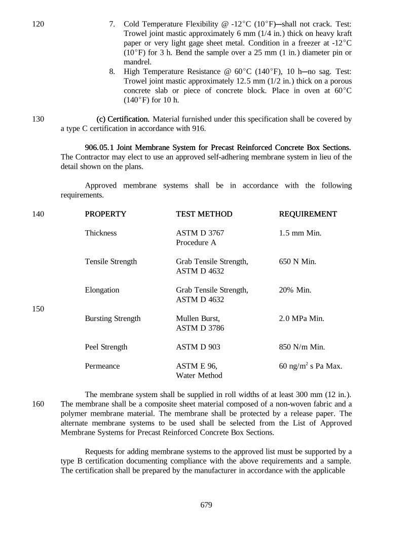
2. Hot Poured2. Hot Poured Joint Sealant Joint Sealant..
a. General Requirementsa. General Requirements. . The sealant shall be in accordance withAASHTO M 301. The material shall be tested in accordance with ASTM D 3407 exceptthat after blotting, the surface of the blocks shall be blown surface dry with compressed50air.
b. Packaging and Markingb. Packaging and Marking. . The sealing compound shall be delivered inthe manufacturer's original sealed container. Each container shall be legibly marked withthe name of the manufacturer, the trade name of the sealer, the manufacturing batchnumber or lot, the pouring temperature, and the safe heating temperature.
c. Requirements for Installationc. Requirements for Installation. . The sealant shall be used in accordancewith the manufacturer's recommendations. A backer rod as set out herein shall be used toprovide the joint configuration in accordance with the standard drawings.60
d. Sampling and Testingd. Sampling and Testing.. Samples may be taken prior to deliveryprovided the plant or warehouse is located in the geographical area serviced by theDepartment's inspectors. If not sampled prior to delivery, it will be sampled at the jobsite. Scheduling shall provide two weeks, after delivery to the Division of Materials andTests for testing. The basis of use will be the applicable laboratory number.
3. Preformed 3. Preformed Elastomeric Joint SealsElastomeric Joint Seals.. This joint seal shall be in accordancewith AASHTO M 220. Joint seals furnished under this specification shall be covered by atype A certification in accordance with 916. Sampling of joint seals in accordance with70
678
AASHTO M 220 will be required. The lubricant-adhesive shall be covered by a type Ccertification in accordance with 916.
(b) Backer Rod(b) Backer Rod.. The rod is to act as a bond breaker, to control the thickness ofthe bead, and to provide support for any required tooling of the sealant.
1. Requirements1. Requirements. . When hot poured material is used, compatibility of thebacker rod with the hot sealant shall be verified before use. The backer rod shall be aclosed cell expanded polyethylene foam or an isomeric polymer foam rod. Diameter andplacement shall be as shown on the plans.80
2. Certification2. Certification.. Backer rod furnished under this specification shall becovered by a type C certification in accordance with 916.
906.03 Joint Mortar906.03 Joint Mortar.. Pipe joint mortar shall consist of one part portland cementand two parts sand with water as necessary to obtain the required consistency. Mortarshall be used within 30 min after its preparation.
906.04 Rubber Type Gaskets906.04 Rubber Type Gaskets.. Ring gaskets for pipe shall be in accordance withAASHTO M 198, type A. Material furnished under this specification shall be covered by90a type B certification in accordance with 916.
906.05 Bituminous Mastic Pi906.05 Bituminous Mastic Pipe Joint Sealerpe Joint Sealer.. This is a cold applied, mineral filled,joint sealing compound for joints of bell and spigot or tongue and groove concrete or claypipe. It shall be a steam refined petroleum asphalt, plasticized to a homogeneousconsistency with mineral fillers.
(a) General Requirements(a) General Requirements. . This sealer shall be a smooth uniform mixture, notthickened or livered, and shall show no separation which cannot be overcome easily bystirring. The material shall be of such consistency and proportions that it can be applied100readily with a trowel, putty knife, or caulking gun without pulling or drawing. It shallexhibit good adhesive and cohesive properties when applied to metal, concrete, or vitrifiedclay surfaces. It shall not be damaged by exposure to below freezing temperatures andshall be applicable when the temperature of the air is between -7EC (20EF) and 38EC(100EF).
(b) Detail Requirements(b) Detail Requirements..
1. When applied in a layer 1 mm (1/16 in.) to 3 mm (1/8 in.) thick on atinned metal panel and cured at room temperature for 24 h, the110bituminous mastic pipe joint sealer shall set to a tough plastic coatingfree from blisters.
Min. Max.2. Grease cone penetration unworked, 150 g,
25EC, 5 s., ASTM D 217, mm/10 .............................125 2253. Non-Volatile, 10 g, 105E C-110EC, 24 h, %................. 754. Ash, by ignition, %................................................ 15 455. Flash Point (ASTM D 92), EC (EF) ............................(38) 1006. Fire Point (ASTM D 92), EC (EF)..............................(66) 150
679
7. Cold Temperature Flexibility @ -12EC (10EF)Cshall not crack. Test:120Trowel joint mastic approximately 6 mm (1/4 in.) thick on heavy kraftpaper or very light gage sheet metal. Condition in a freezer at -12EC(10EF) for 3 h. Bend the sample over a 25 mm (1 in.) diameter pin ormandrel.
8. High Temperature Resistance @ 60EC (140EF), 10 hCno sag. Test:Trowel joint mastic approximately 12.5 mm (1/2 in.) thick on a porousconcrete slab or piece of concrete block. Place in oven at 60EC(140EF) for 10 h.
(c) Certification(c) Certification.. Material furnished under this specification shall be covered by130a type C certification in accordance with 916.
906.05.1 Joint Membrane System for Precast Reinforced Concrete Box Sections906.05.1 Joint Membrane System for Precast Reinforced Concrete Box Sections..The Contractor may elect to use an approved self-adhering membrane system in lieu of thedetail shown on the plans.
Approved membrane systems shall be in accordance with the followingrequirements.
PROPERTYPROPERTY TEST METHODTEST METHOD REQUIREMENTREQUIREMENT140
Thickness ASTM D 3767 1.5 mm Min.Procedure A
Tensile Strength Grab Tensile Strength, 650 N Min.ASTM D 4632
Elongation Grab Tensile Strength, 20% Min.ASTM D 4632
150Bursting Strength Mullen Burst, 2.0 MPa Min.
ASTM D 3786
Peel Strength ASTM D 903 850 N/m Min.
Permeance ASTM E 96, 60 ng/m2 s Pa Max.Water Method
The membrane system shall be supplied in roll widths of at least 300 mm (12 in.).The membrane shall be a composite sheet material composed of a non-woven fabric and a160polymer membrane material. The membrane shall be protected by a release paper. Thealternate membrane systems to be used shall be selected from the List of ApprovedMembrane Systems for Precast Reinforced Concrete Box Sections.
Requests for adding membrane systems to the approved list must be supported by atype B certification documenting compliance with the above requirements and a sample.The certification shall be prepared by the manufacturer in accordance with the applicable
680
requirements of 916. No relabeled materials will be considered for approval. A specifiedmaterial on the approved list will not be listed under more than one name.
170When a product is determined to be acceptable, it will be added to the approved
list and it may be used upon publication of the list.
(a) Type SS(a) Type SS.. Structural steel shall be in accordance with ASTM A 36M(ASTM A 36), A 588M (A 588), A 570M (A 570), A 242M (A 242), or MerchantQuality 1010, 1020.
Sealant and grouts shall be in accordance with Federal Specifications TT-S-00230180or as recommended by the manufacturer.
The elastomer shall be neoprene in accordance with ASTM D 3542 except that thephysical requirements in Table 1 for low temperature recovery, high temperaturerecovery, and compression-deflection properties will not apply.
The structural steel and polyurethane sealant shall be covered by a type Ccertification, and the elastomer shall be covered by a type B certification, both inaccordance with 916.
190(b) Type BS2, BS6, BS8, BS9, BS11, and 1-A(b) Type BS2, BS6, BS8, BS9, BS11, and 1-A.. Materials shall be in
accordance with ASTM D 3542. The dimension and tolerance requirements shall be asspecified in the following table for the type or types of joints specified.
681
EXPANSIONJOINT TYPE SEAL WIDTH SEAL HEIGHT
JOINT WIDTH @INSTALLATION
BS2 41 mm(1 5/8 in.)" 3 mm
(" 1/8 in.)
41 mm(1 5/8 in.)" 3 mm
(" 1/8 in.)
22 mm(7/8 in.)
+ 3 mm, - 6 mm(+ 1/8 in., - 1/4 in.)
BS6 64 mm(2 1/2 in.)
- 0, + 6 mm(- 0, + 1/4 in.)
64 mm(2 1/2 in.)
+ 10 mm, - 3 mm(+ 3/8, - 1/8 in.)
38 mm(1 1/2 in.)
+ 3 mm, - 6 mm(+ 1/8 in., - 1/4 in.)
BS8 76 mm(3 in.)
- 0, + 6 mm(- 0, + 1/4 in.)
83 mm(3 1/4 in.)" 6 mm
(" 1/4 in.)
48 mm(1 7/8 in.)
+ 3 mm, - 6 mm(+ 1/8 in., 1/4 in.)
BS9 100 mm(4 in.)
- 0, + 6 mm(- 0, + 1/4 in.)
111 mm(4 3/8 in.)" 10 mm(" 3/8 in.)
64 mm(2 1/2 in.)
+ 3 mm, - 6 mm(+ 1/8 in., - 1/4 in.)
BS11 127 mm(5 in.)
- 0, + 6 mm(- 0, + 1/4 in.)
128 mm(5 1/8 in.)" 6 mm
(" 1/4 in.)
75 mm(3 in.)
+ 3 mm, - 6 mm(+ 1/8 in., - 1/4 in.)
1-A 16 mm(5/8 in.)" 2 mm
(" 1/16 in.)
17 mm(11/16 in.)" 3 mm
(" 1/8 in.)
6 mm(1/4 in.)
- 0, + 3 mm(- 0, + 1/8 in.)
The material shall be covered by a type A certification in accordance with 916 andsampling of the material will be required. Satisfactory test results shall be obtained fromthe samples prior to the installation of the seal. The lubricant-adhesive shall be covered bya type C certification in accordance with 916.
200(c) Type M(c) Type M.. Structural steel shall be in accordance with ASTM A 36M (A 36),
A 570M (A 570), A 242M (A 242), A 588M (A 588), or Merchant Quality 1010, 1020.
Sealant and grouts shall be in accordance with Federal Specification TT-S-00230or as recommended by the joint manufacturer.
Elastomer shall be neoprene in accordance with ASTM D 3542.
The structural steel and sealant shall be covered by a type C certification and theelastomer by a type B certification, both in accordance with 916.210
682
Bearings above and below the support bar shall be a nylon or urethane compoundwith polytetrafluorethylene riding surfaces. All components of the system shall beaccessible to periodic inspection and component replacement if necessary.
The elastomeric seals shall be in accordance with the requirements as follows:
1. be supplied and installed in one piece;
2. have corner locked edges for a watertight fit;220
3. not be any part of the load bearing riding surface;
4. be installed using seal lubricant-adhesive or be mechanically clampedin position to produce a watertight seal;
5. have a shape which promotes self removal of foreign material duringnormal joint operation;
6. be recessed 13 mm (1/2 in.) below the riding surface throughout the230normal limits of joint movement;
7. be held in position by the separator beams;
8. have a hollow box shape for joints utilizing urethane equilibriumcontrol spacers or a strip seal configuration for joints using amechanical linkage to maintain equidistant separator beam spacing.
The separator beams shall be in accordance with the requirements as follows:240
1. provide the riding surface across the joint;
2. have an extruded or machined shape suitable to hold the seals;
3. be stable against tipping, tilting, or lifting during application of trafficloads by use of a suitable shape and connection to the support bar;
4. be supported individually on their own independent support bars;
5. maintain equidistant spacing through use of suitable urethane250equilibrium type control spacers or through a positive horizontalmechanical linkage or proportioning bar.
The support bars shall be in accordance with the requirements as follows:
1. incorporate stainless sliding surfaces to minimize resistance to jointmovements;
2. be supported above, below, and laterally as required to prevent lifting,to transmit bearing loads, and to maintain positioning of the bar.260
683
All support bar boxes and joint housings shall have top, bottom, and sides made ofsteel plate with 13 mm (1/2 in.) minimum thickness. Anchorages shall consist of loopedNo. 5 reinforcing bars welded to 13 mm (1/2 in.) steel plates spaced at 230 mm (9 in.)centers. No unwelded steel to steel contact will be permitted.
SECTION 907 -- CONCRETE, CLAY, AND PLASTIC DRAINAGE COMPONENTSSECTION 907 -- CONCRETE, CLAY, AND PLASTIC DRAINAGE COMPONENTS
907.01 Non907.01 Non-Reinforced Concrete Pipe-Reinforced Concrete Pipe.. This pipe shall be in accordance withAASHTO M 86M (M 86) for the specified diameter and strength classes. When used forunderdrain, each section of pipe shall not exceed 0.9 m (3 ft) in length.
907.02 Reinforced Concre907.02 Reinforced Concrete Pipete Pipe.. This pipe shall be in accordance with AASHTOM 170M (M 170) for the specified diameters and strength classes. Unless otherwisespecified, pipe wall design and use of elliptical reinforcement in circular pipe are optional.
10When the pipe listed below is specified or permitted, it shall be in accordance with
the class noted.
Extra Strength Reinforced Concrete Pipe ................. Class IVHeavy Duty Reinforced Concrete Pipe ..................... Class VReinforced Concrete Pipe .....................................Class IIIReinforced Concrete Sewer Pipe..............................Class II
Precast reinforced concrete end sections shall be in accordance with the citedspecifications to the extent to which they apply.20
The manufacturer of the steel reinforcement shall furnish to the pipe manufacturera mill test report. The pipe manufacturer shall certify, on furnished forms that:
(a) The pipe has been manufactured in accordance with these StandardSpecifications.
(b) The area of the steel reinforcement per meter (linear foot) of pipe is inaccordance with or exceeds the specification requirements.
30(c) Based on the steel reinforcement manufacturer's mill test report, the steel
used in the pipe is in accordance with the specification requirements.
(d) Copies of the steel reinforcement manufacturer's mill test reports shall beon file and available to review for five years.
907.03 Reinforced Concrete Horizontal Elliptical Pipe907.03 Reinforced Concrete Horizontal Elliptical Pipe. . This pipe shall be inaccordance with AASHTO M 207M (M 207). Certification shall be in accordance with907.02.
40907.04 Precast Concrete Manholes, Inlets, and Catch Basins907.04 Precast Concrete Manholes, Inlets, and Catch Basins.. These units shall be
in accordance with AASHTO M 199M (M 199). References to diameter are applicable tocorresponding dimensions in other than circular sections. Absorption tests will not berequired for flat top or base slabs. Certification shall be in accordance with 907.02.
684
No more than three holes shall be cast or drilled in each section for the purpose ofhandling.
In addition to the requirements of AASHTO M 199M (M 199), the manhole stepsshall be permanently marked with the specific step designation, and the manufacturer's50identification. This marking shall remain exposed after installation.
Steps shall be selected from the list of approved manhole steps. Requests foradding steps to the list shall be accompanied by: a certified test report demonstratingcompliance with AASHTO M 199M (M 199); instruction for proper installation; completeproduct description including the ancillary equipment required for installation; and asample step. The Department may perform a laboratory evaluation of specific steps andmay not add steps to the list which are not furnished with ancillary installation equipment.
907.05 Precast Reinforced Concrete907.05 Precast Reinforced Concrete Box Sections Box Sections.. Box sections with 0.6 m (2 ft)60of cover or greater shall be in accordance with AASHTO M 259M (M 259) and boxsections with less than 0.6 m (2 ft) of cover which are subject to highway loadings shall bein accordance with AASHTO M 273M (M 273). Box sections furnished in accordancewith AASHTO M 259M (M 259) or AASHTO M 273M (M 273) shall have a minimum28 day compressive strength of 34.5 MPa (5,000 psi), as determined by concrete cores.Certification shall be in accordance with 907.02.
Not more than four holes may be cast, drilled, or otherwise neatly made in theshell of each piece of box section for the purpose of handling or laying. The holes shall betapered unless drilled, and the tapered holes shall be filled with portland cement mortar or70with precast concrete plugs, which shall be secured with portland cement mortar or otherapproved adhesive, before backfilling. Drilled holes shall be filled with portland cementmortar.
907.06 Blank907.06 Blank..
907.07 Blank907.07 Blank..
907.08 Clay Pipe907.08 Clay Pipe.. This pipe shall be in accordance with AASHTO M 65 for thespecified diameters and strength classes for circular unperforated pipe. When specified,80the bell shall have integral spacer lugs to provide for an annular opening and self centeringfeature. The pipe may be glazed or unglazed, unless otherwise specified.
907.09 Perforated Clay Pipe907.09 Perforated Clay Pipe.. This pipe shall be in accordance with AASHTOM 65 for the specified dimensions and strength classes. It may be glazed or unglazed,unless otherwise specified. Where vitrified clay culvert pipe is furnished, a pipe endsection compatible to that as required for concrete or metal pipe shall be used.
907.10 Blank907.10 Blank..90
907.11 Drain Tile907.11 Drain Tile.. This pipe shall be in accordance with AASHTO M 178M(M 178) for concrete or M 179 for clay for the specified material, diameters, and qualityclasses. Standard quality drain tile shall not be used. When specified, the pipe spigot shallhave integral spacer lugs to provide for an annular opening and self centering feature.
685
907.12 Blank907.12 Blank..
907.13 Blank907.13 Blank..
907.14 Blank907.14 Blank..100
907.15 Blank907.15 Blank..
907.16 Plastic Pipe Manufacturer Requirements907.16 Plastic Pipe Manufacturer Requirements.. An approved List of Plastic Pipe,Fittings, Solvent Cement, and Elastomeric Seals will be maintained by the Department.The list will specify the manufacturer, plastic pipe, solvent cement, or elastomeric sealsdesignation. All of these materials shall comply with the applicable AASHTO or ASTMrequirements and will only be accepted from qualified manufacturers. The manufacturer isdefined as the plant which produces the plastic pipe, fittings, solvent cements, orelastomeric seals. The manufacturer shall become qualified by establishing a history of110satisfactory quality control of these materials as evidenced by the test results performed bythe manufacturer's testing laboratory.
Manufacturers requesting to be qualified to supply plastic pipe, solvent cements, orelastomeric seals shall submit the following to the Materials and Tests Division.
(a) a quality control plan which encompasses all aspects of the productionprocess starting with the raw materials and concluding with the shipment ofthe finished product. The quality control plan shall provide for a 95% orgreater statistical assurance that the materials will be in accordance with the120specifications, and include type and frequency of sampling and testing;
(b) documentation indicating that the manufacturer's testing laboratory is inaccordance with the provisions of AASHTO R 18;
(c) a monthly summary of all test results for the previous 12 monthsproduction for each type of plastic pipe, fittings, solvent cements andelastomeric seals;
(d) a material safety data sheet for each material produced; and130
(e) To maintain qualification, the manufacturer shall submit to the Materialsand Tests Division a monthly summary of all tests for each type of pipe,pipe fittings, solvent cement, and elastomeric seals produced. If a specifictype of pipe, pipe fitting, solvent cement, or elastomeric seals is notmanufactured in a given month, the monthly submittal shall state: No type____ pipe, pipe fitting, solvent cement, or elastomeric seals wasmanufactured during the month of _____________ 19____.
The manufacturer shall provide the type of certification specified in the Frequency140Manual and in accordance with 916 which designates that hydrostatic design basis, HDB,rated resins or non-HDB rated resins were used in the manufacture of the pipe andfittings.
686
907.17 Corrugated Polyethylene Drainage Tubing907.17 Corrugated Polyethylene Drainage Tubing.. Tubing and fittings shall be inaccordance with AASHTO M 252. Perforations shall be required for tubing used as alongitudinal underdrain. Qualification requirements for the manufacturers shall be inaccordance with 907.16.
907.18 Perforated Polyvinyl Chloride Semicircular Pipe907.18 Perforated Polyvinyl Chloride Semicircular Pipe.. Perforated polyvinyl150chloride semicircular pipe may be used as an alternate to 150 mm (6 in.) or less diameterpipe or tile. Pipe shall be in accordance with ASTM D 3034, SDR 35. This semicircularpipe shall have a smooth top and a smooth, semicircular bottom, nominally 118 mm(4 5/8 in.) in diameter, with perforations uniformly distributed along the top of the bottomsection in accordance with AASHTO M 252 perforation requirements. The top sectionshall extend a minimum of 13 mm (1/2 in.) beyond the top of the semicircular section.The top section shall be approximately 162 mm (6 3/8 in.) wide including the slopingoverhangs on each side. Qualification requirements for the manufacturers shall be inaccordance with 907.16.
160907.19 Corrugated Polyethylene Pipe907.19 Corrugated Polyethylene Pipe.. Pipe and fittings shall be in accordance with
AASHTO M 294. The compound used in manufacturing this pipe shall have a minimumcell class in accordance with 335420C as shown in ASTM D 3350. Qualificationrequirements for the manufacturers shall be in accordance with 907.16.
907.20 Ribbed Polyethylene Pipe907.20 Ribbed Polyethylene Pipe.. Pipe and fittings shall be in accordance withASTM F 894 for the specified sizes. Qualification requirements for the manufacturersshall be in accordance with 907.16.
907.21 Smooth Wall Po907.21 Smooth Wall Polyethylene Pipelyethylene Pipe.. Pipe shall be in accordance with ASTM170F 714 for nominal diameters of 1000 mm (39 in.) or less. Fittings shall be in accordancewith ASTM F 1055. The pipe sizes shall be in accordance with ISO sizing system. Thepipe dimension ratio shall be 26 or less. The compound used in manufacturing this type ofpipe shall have a minimum cell class in accordance with 335434C as shown in ASTMD 3350. Qualification requirements for the manufacturers shall be in accordance with907.16.
907.22 Profile Wall Polyvinyl Chloride Pipe907.22 Profile Wall Polyvinyl Chloride Pipe.. Pipe and fittings shall be inaccordance with AASHTO M 304 for nominal diameters of 900 mm (36 in.) or less.Perforations shall be required when used as a longitudinal underdrain. Qualification180requirements for the manufacturers shall be in accordance with 907.16.
907.23 Smooth 907.23 Smooth Wall Polyvinyl Chloride PipeWall Polyvinyl Chloride Pipe.. Pipe and fittings shall be inaccordance with AASHTO M 278 for pipe sizes 100 mm through 375 mm (4 in.through 15 in.), and ASTM F 679 for pipe sizes 450 mm through 675 mm (18 in. through27 in.). The compound used in manufacturing pipe shall have a minimum cell class inaccordance with 12454C as shown in ASTM D 1784. Qualification requirements for themanufacturers shall be in accordance with 907.16.
907.24 Smooth Wall Pipe for Outlets907.24 Smooth Wall Pipe for Outlets.. Pipe and pipe fittings shall be smooth wall,190non-perforated plastic pipe. Qualification requirements for the manufacturers of thefollowing materials shall be in accordance with 907.16.
687
(a) Type PSM Polyvinyl Chloride Pipe and Fittings(a) Type PSM Polyvinyl Chloride Pipe and Fittings.. Pipe and fittings shall bein accordance with ASTM D 3034, SDR 23.5.
(b) Schedule 40 Polyvinyl Chloride Pipe(b) Schedule 40 Polyvinyl Chloride Pipe.. Pipe shall be in accordance withASTM D 1785 and shall have a minimum pipe stiffness of 1030 kPa (150 psi) at 5%deflection when determined in accordance with ASTM D 2412.
200907.25 Solvent Cements for Polyvinyl Chloride Pipe and Pipe Fittings907.25 Solvent Cements for Polyvinyl Chloride Pipe and Pipe Fittings.. Solvent
cement for polyvinyl chloride pipe and fittings shall be in accordance with ASTM D 2564.Qualification requirements for the manufacturers of this material shall be in accordancewith 907.16.
907.26 907.26 Elastomeric SealsElastomeric Seals.. Elastomeric seals for joining plastic pipe shall be inaccordance with ASTM F 477. Qualification requirements for the manufacturers of thismaterial shall be in accordance with 907.16.
SECTION 908 -- METAL PIPESECTION 908 -- METAL PIPE
908.01 Blank908.01 Blank..
908.02 Corrugated 908.02 Corrugated Steel Pipe and Pipe-ArchesSteel Pipe and Pipe-Arches.. This pipe or pipe-arch and thecoupling bands shall be zinc coated steel or aluminum coated steel in accordance withAASHTO M 36M (M 36), except as noted herein. They may be fabricated withcircumferential corrugations and riveted lap joint construction or with helical corrugationswith continuous lock or welded seam extending from end to end of each length of pipe.Reforming the ends of helical corrugated pipe to form circumferential corrugations will be10permitted to allow use of circumferential corrugated coupling bands. The reforming shallbe limited to the length required to accommodate the coupling bands and in such a mannerthat there is no appreciable slippage of the seam nor a plane of weakness created.
The pipe shall be Type I, IA, II, or IIA.
Band couplers shall have corrugations that mesh with the corrugations of the pipes.
Fittings, including stub-tee connections and saddle connectors specified in 715.06,shall be shop fabricated. Damage to the coating on fittings shall be repaired in accordance20with AASHTO M 36.
If the pipe or pipe-arch invert is to be paved, it shall first be coated over half itscircumference in accordance with 908.07. The paved invert shall then be constructed inaccordance with 908.07.
Sheet metal used to fabricate pipe shall be the same brand from the samemanufacturer in any one length of finished pipe.
The manufacturer shall furnish to the fabricator a certified mill report for materials30shipped to the fabricator. This certified mill report shall list the kind of base metal, actualtest results of the chemical analysis and mechanical tests of each heat, the thickness, the
688
mass (weight) of coating, and shall certify that the material complies with specifiedrequirements for the type of metal furnished.
The fabricator shall certify, on furnished forms that:
(a) the fabricated structure has been manufactured in accordance with theseStandard Specifications;
40(b) based on the sheet manufacturer's certified mill report, the materials used
in fabricating the structure were tested and the test results are in accordancewith the specified requirements; and
(c) Copies of the sheet manufacturer's certified mill report shall be on file andavailable to review for five years.
908.03 Blank908.03 Blank..
908.04 Corrugated Aluminum Alloy Pipe and Pipe-Arches908.04 Corrugated Aluminum Alloy Pipe and Pipe-Arches. . Pipes, pipe-arches,50and coupling bands shall be in accordance with AASHTO M 196M (M196). The pipeshall be Type I, IA, II, or IIA. If the pipe invert is to be paved, it shall be in accordancewith 908.07.
The sheet manufacturer's certified mill report and the fabricator's certificationshall be in accordance with 908.02, except the documents shall be in accordance with theapplicable requirements of AASHTO M 196M (M196).
Where aluminum alloy pipe culvert is furnished, aluminum alloy end sections shallalso be furnished. All component parts shall be aluminum alloy.60
908.05 Blank908.05 Blank..
908.06 Metal End Sections908.06 Metal End Sections.. The end section's metal shall be in accordance withAASHTO M 36M (M 36) or M 196M (M 196), whichever is applicable. The sheet metalmanufacturer's certified mill report and the fabricator's certification shall be in accordancewith 908.02 or 908.04, whichever is applicable.
End sections consisting of multiple panels shall have lap seams which shall betightly jointed with M10 (3/8 in.) galvanized rivets or bolts.70
All steel pipe end sections shall have a toe plate anchor constructed of 3.5 mm(0.138 in.) thick galvanized steel. The toe plate anchor shall be match punched to fit holesin the skirt lip, and shall be supplied loose, and complete with M10 (3/8 in.) diametergalvanized bolts.
Straps for pipe end sections shall be either galvanized 20M (No. 6) reinforcingbars or zinc coated 10 mm (3/8 in.) diameter aircraft cable.
908.07 Fiber Bonded Fully Bituminous Coated Corrugated Steel Culvert Pipe and908.07 Fiber Bonded Fully Bituminous Coated Corrugated Steel Culvert Pipe and80Pipe-ArchesPipe-Arches.. The material, fabrication, the manufacturer's certified mill report, and
689
fabricator's certification shall be in accordance with the applicable requirements of908.02. The fiber bonding requirements shall be as described herein. Coupling bands shallbe fiber bonded fully bituminous coated.
The fibers used in the bonding process shall be aramid. The fibers shall be appliedevenly in sheet form on both sides of the steel sheet by embedding them into a molten zincbonding medium. Immediately after solidification of the zinc bonding medium, the fibersshall be thoroughly impregnated with an asphalt saturant. The finished steel sheets shall befree from blisters and unsaturated areas. The steel sheets shall then be corrugated and90fabricated into culvert. After fabrication, the pipe or pipe-arch shall be fully bituminouscoated.
Connecting or coupling bands shall be of the 2-piece type when used with coatedpipe of 900 mm (36 in.) diameter or larger.
The asphalt material for coating shall be in accordance with 902.02. Samples ofthe asphalt material will be obtained from the working tank prior to or during coating ofthe pipe, or from strippings off the pipe after coating. When applied to the pipe, theasphalt material shall be free from impurities. The metal shall be free from grease, dust,100or moisture. Either process set out below may be used for application.
(a) When the pipe is not preheated, the temperature of the asphalt at the timeof immersion shall be 204EC " 3EC (400EF " 5EF). The duration of theimmersion in the asphalt shall be in accordance with the following:
MinimumImmersionTime for firstDip (min) 2.0 2.5 3.0 5.0 6.5 8.0
(b) When the pipe is preheated it shall be brought to a temperature of 149EC(300EF) and the asphalt shall be heated to a temperature of 193EC " 3EC(380EF " 5EF) before the pipe is dipped.110
In either process, the pipe shall be dipped a second time or more if necessary, togive a minimum thickness of 1.3 mm (0.05 in.).
If paved invert is specified, the pipe or pipe-arch shall first be fully coated asrequired. Additional bituminous material shall be applied in the bottom section to form asmooth pavement. Except where the upper edges intersect the corrugations, the pavementshall have a minimum thickness of 3 mm (1/8 in.) above the crests of the corrugations.The pavement shall be applied to the lower quarter of the circumference.
120The manufacturer of the asphalt material shall furnish to the pipe fabricator the
type of certification specified in the Frequency Manual and in accordance with 916 for
690
each shipment or lot of asphalt material. The pipe fabricator shall keep these certificationson file and available to review for five years. In addition, samples from the working tankwill be obtained for verification of requirements.
908.08 Polymer 908.08 Polymer Precoated Galvanized Corrugated Steel Culvert Pipe andPrecoated Galvanized Corrugated Steel Culvert Pipe andPipePipe-Arches-Arches.. The pipe or pipe-arch and coupling bands shall be in accordance withAASHTO M 245M (M 245) with additions in accordance with 908.02. The polymerprecoated galvanized steel sheets shall be in accordance with AASHTO M 246M (M 246),130Grade 250/250 (10/10).
908.09 Structural Plate Pipe, Pipe-Arches, and Arches908.09 Structural Plate Pipe, Pipe-Arches, and Arches..
(a(a) Steel) Steel.. Steel structural plate pipe, pipe-arches, and arches shall beconstructed from individually galvanized corrugated steel plates as described herein. Forpipes and pipe-arches having a thickness less than 7.11 mm (0.280 in.), the bottom platesshall be of the next greater thickness than that specified for the top and side plates, notincluding corner plates for pipe-arches. The individual plates shall be in accordance withAASHTO M 167M (M 167) and Section 26 of the AASHTO Standard Specifications for140Highway Bridges, Division II.
The materials and fabrication shall be as follows:
1. The minimum corner plate radius of the arc joining the top and bottomplates of pipe-arches shall be 457 mm (18 in.) for openings up to andincluding 12.2 m5 (131 sq ft) and 787 mm (31 in.) for openings over12.2 m5 (131 sq ft). The minimum radius of the arc shall be 787 mm(31 in.) for openings from 9.1 m5 (98 sq ft) up to and including19.8 m5 (214 sq ft).150
2. Assembly bolts shall be in accordance with AASHTO M 164M(M 164), ASTM A 325M (A 325), or ASTM A 449. Nuts shall be inaccordance with ASTM A 563M (A 563), class 8S (grade C);AASHTO M 164M (M164); or ASTM A 325M (A 325). Assemblybolts, nuts, and washers shall be galvanized in accordance withASTM A 153, or be mechanically galvanized and conform to thecoating thickness, adherence, and quality requirements of ASTMA 153, class C.
1603. The sheet manufacturer's certified mill report and the fabricator's
certification shall be furnished in accordance with 908.02, except thedocuments shall be in accordance with the applicable requirements ofAASHTO M 167M (M 167).
(b) Aluminum Alloy(b) Aluminum Alloy.. Aluminum alloy structural plate pipe, pipe-arches, andarches shall be in accordance with AASHTO M 219M (M 219). The sheetmanufacturer's certified mill report and the fabricator's certification shall be furnished inaccordance with 908.02.
170
691
908.10 Cast Iron Soil Pipe908.10 Cast Iron Soil Pipe.. This pipe shall be in accordance with ASTM A 74.Markings shall be in accordance with ASTM A 74 or ANSI A 40.1.
908.11 Steel Pipe908.11 Steel Pipe.. This item shall be electric-fusion, arc-welded steel pipe inaccordance with ASTM A 139, grade B, or electric-resistance welded pipe in accordancewith ASTM A 53, Type E, Grade B, as applicable. Material furnished under thisspecification shall be covered by the type of certification specified in the FrequencyManual and in accordance with 916.
908.12 Straps, Hook Bolts and Nuts Used in Anchors908.12 Straps, Hook Bolts and Nuts Used in Anchors.. Straps shall be of the type180and size shown on the plans. Reinforcing bars used for straps shall meet the applicablerequirements of 910.01 and shall be galvanized in accordance with ASTM A 767M(A 767), class I. Aircraft cable used for straps shall be made of zinc coated steel wire,9.5 mm (3/8 in.) nominal diameter, consisting of seven 19 wire flexible steel strands, witha minimum breaking strength of 62.3 kN (14,000 lb). The cable shall be in accordancewith Military Specification MIL-W-1511.
Hook bolts and nuts shall be of the size shown on the plans, shall be in accordancewith the applicable requirements of ASTM A 307, and shall be galvanized in accordancewith ASTM A 153. Threads shall be American Standard Coarse Thread Series Class 2 fit.190Threads shall be cleaned after galvanizing to provide a free running fit. Maximumoversizing of the nut threads shall be 0.4 mm (1/64 in.).
908.13 Fully Bituminous Coated and Lined Corrugated Steel Pipe and908.13 Fully Bituminous Coated and Lined Corrugated Steel Pipe andPipePipe-Arches-Arches.. The material, fabrication, bituminous coating, and 100% paving shall be inaccordance with the applicable requirements of 908.02 and 908.07. Coupling bands shallbe fully bituminous coated.
908.14 Slotted Drain or Slotted Vane Drain Pipe908.14 Slotted Drain or Slotted Vane Drain Pipe.. Slotted drains shall bemanufactured from helically corrugated steel pipe in accordance with AASHTO M 36M200(M 36). At the end of the pipe there shall be two annular corrugations to permit thecorrugated band to fully mesh with the pipe.
The grated assembly shall be made of structural steel in accordance with AASHTOM 183M (M 183), Grade 36. The assembly shall be suitably welded to the pipe andgalvanized after assembly in accordance with AASHTO M 111. The grate shall be of thesize and spacing shown on the plans and shall be welded on both sides to each bearing barwith a 5 mm (3/16 in.) fillet weld.
The size and thickness of the corrugated steel slotted drain pipe shall be as shown210on the plans.
Slotted vane drain pipe shall be polyvinyl chloride in accordance with 907.23, andshall be of the diameter specified. The casting shall be in accordance with 910.05(b). Thefinish shall be standard black asphalt emulsion. Individual units shall have a minimummass (weight) of 70 kg (155 lbs).
692
SECTION 909 -- PAINT AND LIQUID EPOXYSECTION 909 -- PAINT AND LIQUID EPOXY
909.01 General Requirements909.01 General Requirements.. All necessary facilities for inspection of materialsand manufacture of paints, enamels, varnish, and ingredients shall be granted. Free accessto all parts of the premises where any or all of these products are being prepared shall beallowed. Material Safety Data Sheets shall be provided.
Paint shall be furnished ready for use without modification and shall not settle,cake, curdle, liver, gel, or develop excessive change in viscosity between time ofmanufacture and time of use. It shall remain capable of being readily dispersed with a10paddle, or other approved methods, to a consistency appropriate for the intended use.Paint may be sampled and tested at any time prior to use. If, for any reason, re-samplingand retesting following initial or prior approval is indicated, the latest test results shallprevail over all previous tests for material that has not been used. Previously approvedpaint which is later stored may be re-sampled and retested.
Paint shall be delivered in new containers of such strength, durability, design,fabrication, and material that the paint shall be suitably protected in transit and in storageagainst any change in characteristics which would cause rejection on the basis oflaboratory or field evaluation. Each container shall bear a label which shows the name and20address of the manufacturer, kind of paint, formula identification date of manufacture, andlot or batch number. The mass per volume (weight per gallon) kg/L (lb per gal.) of thepaint shall be accurately determined at 25EC (77EF). The container shall be so filled thatthe net mass (weight) of the material in the container shall be the product of the mass pervolume (weight per gallon) at 25EC (77EF) and the stated number of liters (gallons) in thecontainer.
All labels shall be in accordance with the OSHA requirements for labeling ofhazardous chemicals as described in the Hazardous Communications Standard.
30909.02 For Metal909.02 For Metal.. Paints for metal surfaces shall be in accordance with the
requirements shown below.
(a) Zinc Primers(a) Zinc Primers..
1. Two Component and Multi-Component Inorganic Zinc Silicate Primer1. Two Component and Multi-Component Inorganic Zinc Silicate Primer..These paints shall be of the self-cure type which, when mixed and applied in accordancewith these specifications, shall cure without the use of a separate curing solution. Themulti-component inorganic zinc silicate primers shall have a maximum of threecomponents. The components of each type of paint shall be packaged in such proportions40that when the full quantity of each component is mixed together, the specified mixed paintshall be yielded.
These paints shall be in accordance with the following requirements.
a. Two component solvent based primer shall be in accordance withAASHTO M 300 Type I.
693
b. Multi-component solvent based primer, with low volatile organiccompounds for shop painting, shall be in accordance with AASHTO50M 300 Type IA.
c. Two component water based primer shall be in accordance withAASHTO M 300 Type II.
2. Single Package Inorganic Zinc Silica2. Single Package Inorganic Zinc Silicate Primerte Primer.. The Inorganic ZincSilicate Primer shall be a single package, self-curing type which, when stirred and appliedin accordance with these specifications, cures without the use of a separate curingsolution. It shall be in accordance with AASHTO M 300 Type III.
603. Organic Zinc Primer3. Organic Zinc Primer. . Organic zinc primer shall be a self-curing type
paint. It shall be in accordance with SSPC paint specification No. 20 type II withexceptions as follows:
Table I, total zinc dust, percent by mass (weight) of pigment requirement shall bea minimum of 87% metallic zinc. Table I, total zinc dust, percent by mass (weight) oftotal solids requirement shall be a minimum of 72% metallic zinc.
The organic zinc primer shall also be in accordance with the requirements asfollows:70
a. The viscosity shall be 70 to 100 kreb units.
b. The mass per volume (weight per gallon) shall be a minimum of2.04 kg/L (17.0 lb/gal.).
c. The dry time shall be a maximum of 1 h set-to-touch and 24 h dryhard when applied at 150 :m (6 mil) blade clearance to a tin coatedsteel panel at 25EC and 60% " 5% relative humidity.
80d. The infrared spectrum of the vehicle shall match the infrared
spectrum of the vehicle of the sample submitted for formulationapproval.
e. The organic zinc primer shall not exceed 0.419 kg/L (3.50 lb/gal.)volatile organic compounds. The cured film shall not contain toxicheavy metals above the regulatory levels of 40 CFR 261.24.
f. The organic zinc primer shall be compatible with inorganic zinc andfinish coat paints already on the bridge. The color shall be able to90produce a distinct contrast with blast cleaned metal surface and thefinish coat. The cured organic zinc film shall be compatible with atop coating of waterborne finish coat paint.
4. Approval of Formulation4. Approval of Formulation.. The manufacturer shall obtain approval of theformulation prior to furnishing the primers. To obtain approval, the manufacturer shallsubmit to the Division of Materials and Tests the following:
694
a. A certified test report from an approved independent testinglaboratory showing specific test results for all applicable quantitative100requirements and resistance test requirements in these specifications.The report shall state the manufacturer's name, brand name of paintincluding formulation number, date of manufacture, number of thebatch tested, beginning and ending dates of resistance tests, and, forthe 2-component or multi-component paints, the exact mass (weight)ratio of each component used in the mixed paint tested.
b. A certification, in accordance with the applicable requirements of916, indicating compliance with the requirements for the specificprimer set out in these specifications.110
c. A current material safety data sheet shall be submitted with theinitial formulation approval package.
5. 5. Reapproval of FormulationReapproval of Formulation.. Reapproval will be required:
a. every five years;
b. each time there is a change in formulation or the manufacturingprocess;120
c. if three consecutive years elapse without furnishing material;
d. it may be required when test of material furnished indicatenon-conformance with any of the specified requirements.
(b) Epoxy Intermediate Paint(b) Epoxy Intermediate Paint.. Epoxy intermediate paint shall be a twocomponent coating consisting of an epoxy resin and a curing agent, together with primeand filler pigments, colorants, gellant, leveling agents and solvents. When mixed, thiscoating shall be suitable for application over inorganic and organic zinc primers and shall130be compatible with a polyurethane finish coat. The color of this coating shall contrastsignificantly from the other coatings within the coating system.
The mixed paint shall be in accordance with the requirements as follows:
Volatile organic compounds, ASTM D 3960, Max. ........................ 336 g/LVolume solids, ASTM D 2697, Min............................................... 60%Set-to-touch, ASTM D 1640, 175 µm wet film, 25 " 1EC, Max.........................................................................4 hPotlife, 25 " 1EC, Min. ................................................................6 h140Mass (weight)/volume variance from the initially approved batch, ASTM D 1475, 25EC, Max. ...................................... 0.060 kg/LTotal solids variance from the initially approved batch, ASTM D 2369, Max. .............................................................. 3.0%
The infrared spectra of each component and of the mixed coating shall essentiallymatch the spectrums of the initially approved batch.
695
(c) Polyurethane Finish Coat(c) Polyurethane Finish Coat.. Polyurethane finish coat shall be a twocomponent polyester or acrylic aliphatic polyurethane suitable for use as a finish coat over150epoxy intermediate paint.
The mixed paint shall be in accordance with the requirements as follows:
Volatile organic compounds, ASTM D 3960, Max. ........................ 336 g/LVolume solids, ASTM D 2697, Min............................................... 60%Set-to-touch, ASTM D 1640, 127 µm wet film, 25 " 1EC, 50 " 10% relative humidity, Min. ............................................. 30 minTotal Solids ASTM D 2369, Min................................................... 70%Specular gloss, 60E, ASTM D 523, Min.............................................75160Viscosity, ASTM D 562, Kreb Units, Max........................................ 100Contrast ratio, ASTM 2805, 127 µm wet film thickness dried 24 h @ 25 " 2EC on Leneta Form 2A or 2C, Min..................... 0.95Dry hard, ASTM D 1640, 127 µm wet film, 25 " 1EC, 50 " 10% relative humidity, Max. ............................................... 24 h
The infrared spectra of each component and of the mixed coating shall essentiallymatch the spectrums of the initially approved batch.
The color of the dried paint film shall match the color number of Federal Standard170595a as follows:
Color No. Color14260 Green15450 Light Blue17886 White13538 Yellow13711 Buff17038 Black
(d) Waterborne Finish Paint(d) Waterborne Finish Paint.. The waterborne finish coating shall be a singlepackage, high build acrylic emulsion for use as a finish coat over inorganic and organiczinc primers. It shall be compatible with and adhere to the cured zinc primers.
1. Vehicle Component1. Vehicle Component.. The vehicle shall consist of an acrylic emulsiontogether with the necessary antifoamers, cosolvents, coalescing agent, preservatives, andantifreeze in order to produce a coating in accordance with this specification.180
2. Pigment Component2. Pigment Component.. The active pigment shall consist of titaniumdioxide in accordance with ASTM D 476, type IV, and non-reactive color retentive tintingpigments. The pigment shall contain extenders and additives as required for properapplication.
3. Mixed Paint Properties3. Mixed Paint Properties.. The mixed paint shall be in accordance with therequirements as follows:
696
Viscosity, ASTM D 562, Kreb Units ......................................... 80 - 100190Mass (weight)/volume, ASTM D 1475, deviation from approval formulation, Max................................. 0.024 kg/L (0.2 lb/gal.)Pigment grind, ASTM D 1210, Hegman, Min....................................... 5Total solids, % by mass (weight), ASTM D 2369, Min...........................50Vehicle solids, % of vehicle by mass (weight), Min. ..............................40Dry time, ASTM D 1640, 75 µm (3 mils) wet film on a tin coated steel panel @ 25 " 1EC and 50 " 5% relative humidity, Max: Set-to-touch, h .......................................................................... 1 Dry hard, h.............................................................................24200Hiding power, 150 µm 6 (mils) wet film on morest black and white chart paper, dry film hiding.............................. CompleteSpecular gloss, 60E, 250 µm (10 mils) wet film on a tin coated panel, dried 48 h @ 25EC and 50 " 5% relative humidity, ASTM D 523 ......................................................... 15 - 25pH, ASTM E 70 .................................................................. 7.0 - 9.0Volatile organic compounds, ASTM D 3960 Max.0.180 kg/L (1.50 lb/gal.)
The infrared spectrum of the vehicle when extracted from the mixed paint in210accordance with ASTM D 3168 shall match the infrared spectrum of the sample submittedfor formulation approval.
The mixed paint shall be in accordance with the requirements of Sections 5.4through 5.17 of SSPC paint specification No. 24.
The cured waterborne finish paint shall not contain toxic heavy metals above theregulatory levels of 40 CFR 261.24.
4. Color4. Color.. The color of the dried paint film shall match the color number of220Federal Standard 595a as follows:
Color No. Color24227 Green24466 Light Green25526 Light Blue27780 White23538 Yellow23717 Buff27038 Black
5. Approval of F5. Approval of Formulationormulation.. The manufacturer shall obtain approval of theformulation prior to furnishing the waterborne finish paint. The formulation approval shallbe in accordance with 909.02(a)4 and 909.02(a) 5.
697
(e) F(e) Finish Coat for Weathering Steelinish Coat for Weathering Steel.. The finish coat shall be an aliphaticpolyurethane or a waterborne acrylic paint. It shall be suitable for use as a finish coat overepoxy intermediate paint. The mixed paint shall be in accordance with the requirements as230follows:
Specular gloss, 60E, ASTM D 523, Max. ..........................................6.0Viscosity, ASTM D 562, Kreb Units, Max........................................ 100Mass (weight)/volume variance from the initially approved batch, ASTM D 1475, 25EC, Max. ..................................... 0.048 kg/LTotal solids variance from the initially approved batch, ASTM D 2369, Max....................................................... 2.0%Volatile Organic Compounds, ASTM D 3690, Max........................ 336 g/L
240The dried paint film shall match color number 30045 of Federal Standard 595a.
909.03 Structural Steel Coating System909.03 Structural Steel Coating System.. This coating system shall consist of aninorganic zinc primer, an epoxy intermediate paint, and a polyurethane finish coat for thepainting of steel bridges and other structural steel. All of the coatings within any coatingsystem shall be manufactured by the same manufacturer and shall be compatible with oneanother. All coatings shall be in accordance with 909.02.
(a) Toxicity(a) Toxicity.. The cured film of each coating within the structural steel coatingsystem shall not contain any toxic heavy metals above the limits of the regulatory levels of25040 CFR 261.24, table 1, when tested in accordance with EPA TCLP, or contain any othermaterial which will require characterization as a hazardous waste for the disposal of thedried film.
(b) Resist(b) Resistanceance.. The coating system shall be tested in accordance with therequirements of NEPCOAT, Specification Criteria For Protective Coatings, datedJune 6, 1996. The coating system shall be in accordance with all of the acceptance criteriaand shall maintain a specular gloss retention of 60% relative of the initial gloss and amaximum color change of 15 ∆E for Test No. 3, Weathering Resistance.
260(c) Approval of Structural Steel Coating System(c) Approval of Structural Steel Coating System.. The manufacturer shall obtain
approval of each structural steel coating system prior to furnishing any of these coatings.An approved list of Structural Steel Coating Systems will be maintained by theDepartment. The list will specify the manufacturer's designation of each coating ofstructural steel coating system. Manufacturers who desire to have products added to thelist of Structural Steel Coating Systems shall submit the following documentation to theMaterials and Tests Division.
1. A certified test report from an independent testing laboratory whichprovides test results for all quantitative requirements and resistance test270requirement for each coating and for the coating system in thesespecifications. The test report shall include the manufacturer's name,brand name of each coating, formulation identification of each coating,batch numbers, beginning and ending dates of each test, date ofmanufacture for each coating, and the exact mass (weight) and volumeratio of each component used for mixing multiple component coatings.
698
2. Material safety data sheet for each coating.
3. Product data sheet for each coating. The product data sheets shall be in280accordance with NEPCOAT Specification Criteria For ProtectiveCoatings, dated June 6, 1996.
4. A QCP which includes all aspects of the production process for eachcoating, starting with raw materials and concluding with the shipmentof the finished products. The QCP shall include sampling and testingfrequency and specific test used for the quality control of eachproduct.
5. Documentation of quality assurance within the manufacturer's290laboratory.
6. Performance history indicating that the specific coating system hasperformed successfully for a minimum of three years. Theperformance history shall include the name, address and telephonenumber of the structure owner including the name of a responsiblecontact person, location of the structure and dates of coatingapplication and inspection.
((d) Structural Steel Coating System Re-approval.d) Structural Steel Coating System Re-approval. Re-approval will be required300as follows:
1. each time there was a change in the formulation or the manufacturingprocess of each coating;
2. if three consecutive years elapse without furnishing any of theapproved coatings;
3. when testing of the coating furnished indicates continualnon-compliance with the specifications; and310
4. when field evaluations indicate that the coating system does notprovide the required protection to the structural steel.
909.04 Field Paint for Wood or Metal909.04 Field Paint for Wood or Metal.. The primers for field paint shall beformulated for minimal surface preparation, provide adhesion to the substrate and becompatible with the finish coat. The primers shall not contain lead, chromium or otherheavy metals which would require classification as a hazardous waste upon removal. Theprimers shall comply with the current IDEM VOC regulations and shall be used asfollows:320
a. For unpainted galvanized steel and other ferrous metals, use onecoat of a zinc dust-zinc oxide pigmented primer.
b. For non-ferrous metals, use one coat of primer formulated for useon non-ferrous metals.
699
The field paint finish coat shall be an exterior type coating. It shall be chalkresistant, gloss retentive and suitable for application by brush, roller or spray. This coatingshall comply with the current IDEM VOC regulations and shall not contain lead,330chromium or other heavy metals which would require classification as a hazardous wasteupon removal. The color of this coating shall be as specified.
909.05 White and Yellow Traffic Paint909.05 White and Yellow Traffic Paint..
(a) Standard Traffic Paint(a) Standard Traffic Paint..
1. General Requirements1. General Requirements. . White and yellow traffic paint shall be used onpavements for centerlines, lane lines, or as otherwise specified. In addition to its otherrequirements, when glass beads are applied, it shall be such that it shows capillary action340in the interstices and voids existing between the beads sufficient to cause the level of thepaint to be raised approximately 2/3 the diameter of the beads to provide anchorage andrefraction. The capillary action shall be such that it does not cause complete envelopment.The paint, as furnished, shall contain no glass beads.
The paint shall be ground to a uniform consistency and shall permit satisfactoryapplication by the pressure spray type of painting machine currently in use by theDepartment. This painting equipment is designed to apply reflectorized lines, using thedrop-on bead method, 100 mm (4 in.) to 150 mm (6 in.) wide, at a wet film thickness of0.381 mm (0.015 in.) on clean, dry pavements at ambient temperatures of 4EC (40EF) or350higher at speeds of 16.09 to 24.14 km/h (10 to 15 mph). The material shall have physicalcharacteristics which permit it to be pumped through gear type pumps from the shippingcontainer into the paint tanks, and by compressed air from the paint tanks through thepaint machine plumbing system at a minimum ambient temperatures of 4EC (40EF).
The paint shall be furnished ready for use without thinning or other modificationand shall not settle, cake, curdle, liver, gel, or show excessive change in viscosity in thecontainer during a period of one year after manufacture and shall be capable of beingbroken up with a paddle to a smooth consistency. The manufacturer shall furnish anynecessary information as to special storage requirements. The paint may be rejected if it360contains skins, thickened or jelly-like layers or lumps, coarse particles, dirt, or otherforeign material. The composition of the pigments and vehicles of the paints are at theoption of the manufacturer, provided the paints conform with the requirements specifiedherein.
The paint shall be supplied in new removable head 210 L (55 gal.) drums whichconform to DOT Specification 17-H, or in new 19 L (5 gal.) removable lid bucketsconforming to the appropriate DOT Specifications. The drums shall be filled with 190 L(50 gal.) of paint. Volume measurements shall be based on a liquid temperature of 25EC(77EF). Drums shall be provided with reusable multiseal sponge gaskets, of a type which370prevents the paint from skinning during storage, and shall be equipped with outsidelocking rings or clamps. Each drum shall show true mass (weight), gross mass (weight),net mass (weight), equivalent net volume (gal.), name and address of manufacturer, batchnumber, kind of paint, color, and date of manufacture.
700
2. Specific Requirements2. Specific Requirements..
Min. Max.Pigment, Federal Standard 141A, Method 4022,
percent by mass (weight) ...............................................54 60380Titanium Dioxide, ASTM D 476, Types II, III, or IV,
white only, g/L (lb/gal.) of paint.................................. 96 (0.8) ---Medium Chrome Yellow, ASTM D 211, Type III,
yellow only, g/L (lb/gal.) of paint, ............................. 144 (1.2) ---Other pigments may be used provided the amount of pigment is such that therewill be a minimum of 0.125 kg of pure lead chromate per liter (1.04 lb/gal.) ofpaint.Vehicle Solids, percent of vehicle by mass (weight), Federal
Standard 141A, Method 4053 .........................................40 ---Total Non-Volatiles, Federal Standard 141A,390
Method 4042, percent by mass (weight).............................74 ---Viscosity @ 25EC (77EF), ASTM D 562, Krebs Units................70 80Luminous Directional Reflectivity, ASTM E 308
or E 97, percentWhite.......................................................................84 ---Yellow .....................................................................50 ---
Color, yellow only, x-y C.I.E. coordinates forgreen limit, FHWA color chart of June 1965.......................Match the
green limit " 8%Dry time to no pick-up ASTM D 711, wet film400
Contrast ratio, ASTM D 2805, wet film 380 " 25:m(15 " 1 mil), black - white chart paper, air driedat least 16 h ...............................................................0.96 ---
Flexibility, Federal Specifications TT-P-85D .......................... No breakingor cracking
Uncombined (free) water, percent, Federal Standard 141A, Method 4081..........................................................--- 1.0
410(b) Fast Dry Traffic Paint(b) Fast Dry Traffic Paint..
1. General Requirements1. General Requirements.. The general requirements specified for standardtraffic paint in 909.05(a)1 shall apply except as modified herein.
The paint shall be ground to a uniform consistency, and it shall permit satisfactoryapplication by the pressure spray type of painting machine currently in use by theDepartment. This painting equipment is designed to apply reflectorized lines, using apressurized bead application method, 100 mm to 150 mm (4 to 6 in.) wide, at a wet filmthickness of 380 :m (0.015 in.) on clean dry pavement, with the material being heated at420a maintained temperature from ambient air temperature to a maximum of 82EC (180EF),at the atomized spray gun, at a minimum ambient temperature of 4EC (40EF). Thematerial shall be capable of being applied under these conditions at speeds of 16 to24 km/h (10 to 15 mph). The material shall have physical characteristics which permit it
701
to be pumped at a minimum temperature of 4EC (40EF) through pumps from the shippingcontainer into the paint tank on the paint machine, and then by pumps through the paintmachine plumbing system to and through the heat exchanger and to the spray gun at theproper pressure and temperature.
2. Specific Requirements2. Specific Requirements. . The paint shall dry to a no tracking condition in430no more than 60 s. The no tracking condition shall be determined by actual application onthe pavement at a wet film thickness of 380 :m (15 mils) with white or yellow paintcovered with glass beads at a rate of 0.7 kg/L (6 lb/gal.). The paint lines for this test shallbe applied with the specialized striping equipment operated so as to have the paint attemperatures up to 82EC (180EF) at the spray orifice. This maximum no tracking timeshall not be exceeded when the pavement temperature varies from 2EC (35EF) to 49EC(120EF), and under all humidity conditions providing that the pavement is dry. The notracking time shall be determined by passing over the paint line 60 s after paintapplication, in a simulated passing maneuver at a constant speed of 48 to 64 km/h (30 to40 mph) with a passenger car. A line showing no visual deposition of the paint to the440pavement surface when viewed from a distance of approximately 15 m (50 ft) from thepoint where the test vehicle has crossed the line shall be considered as showing notracking and conforming to the requirement for field drying conditions. This field dry timetest shall be used for production samples only.
In addition to the above, the paint shall meet the following requirements:
Min. Max.Pigment, Federal Standard 141A, Method 4022, percent by mass (weight) .................................................. 54 60450Titanium Dioxide, ASTM D 476, Types II, III, or IV, white only, g/L (lb/gal.) of paint..................................... 96 (0.8) ---Medium Chrome Yellow, ASTM D 211, Type III, yellow only, g/L (lb/gal.) of paint ................................. 144 (1.2) ---Other Pigments may be used, provided the amount of pigment is such thatthere will be a minimum of 0.125 kg/L (1.04 lbs/gal.) of pure lead chromateper gallon of paint.Vehicle Solids, percent of vehicle by mass (weight), Federal Standard 141A, Method 4053 ............................................ 35 ---Total Non-Volatiles, Federal Standard 141A,460 Method 4042, percent by mass (weight) ................................ 72 ---Viscosity @ 25EC (77EF), ASTM D 562, Krebs Units................80 100Luminous Directional Reflectivity, ASTM E 308 or E 97, percent White..........................................................................84 --- Yellow ........................................................................50 ---Color, yellow only, x-y C.I.E. coordinates for green limit, FHWA color chart of June 1965.......................... Match the
green limit " 8%Contrast ratio, ASTM D 2805, wet film 380 " 25 :m470 (15 " 1 mil) black - white chart paper, air dried at least 16 h ......................................................0.96 ---
702
Uncombined (free) Water, Federal Standard 141A,Method 4081, percent .......................................................--- 1.0
(c) White and Yellow (c) White and Yellow Waterborne Traffic PaintWaterborne Traffic Paint.. White and yellowwaterborne traffic paints shall consist of an emulsion of pigmented binder.
When glass beads are induced into the paint lines, the paint shall providecapillary action in the interstices and voids between the glass beads sufficient to cause480the level of paint to raise approximately two thirds the diameter of the glass beads. Thiscapillary action shall not cause complete envelopment of the glass beads. The paint asfurnished shall not contain glass beads. The paint shall be ground to a uniformconsistency, and it shall permit satisfactory application by the pressure-spray type ofpainting equipment. The painting equipment shall use a pressurized bead applicationmethod that is designed to apply 100 to 150 mm (4 to 6 in.) reflectorized paint lines atpaint temperature up to 65EC (150EF). The paint shall be capable of being applied atspeeds of 15 to 25 km/h (10 to 15 mph).
The paint shall not darken under the heating conditions of application, or show490appreciable discoloration due to sunlight exposure and aging of the paint lines. Thepaint shall be furnished ready for use without thinning, screening, or othermodifications and shall not settle, cake, curdle, liver, gel, or have an excessive changein viscosity in the container during a period of one year after manufacture. The paintshall be capable of being stirred to a uniform consistency. The paint shall be able towithstand variations of temperatures when stored outside in the containers as delivered,and in an environment above 5EC (40EF). All paint furnished under these specificationswill be rejected if it contains skins, thickened or jelly-like layers, lumps, coarseparticles, dirt, or other foreign materials which prevent the proper application of thepaint, or produces a non-uniform paint line. All paint which cannot be transferred by500pumps on the paint equipment from the shipping containers and through the paintequipment due to excessive clogging of screens, filters, or paint guns will be rejected.
The paint shall dry to a no-tracking condition in less than 60 s. The no-trackingcondition shall be determined by actual application of the paint on the pavement at awet film thickness of 380 Fm (15 mils) with glass beads applied at a rate of 0.7 kg/L(6 lb/gal.). The paint lines for the determination of no-tracking condition shall beapplied with the specialized painting equipment operated so as to have the paint atapplication temperatures up to 60EC (140EF) at the spray guns. The maximumno-tracking time shall not be exceeded when the pavement temperature varies from51010EC to 50EC (50EF to 120EF), and with all relative humidity conditions providing thatthe pavement is dry. The no-tracking time shall be determined by passing over the paintline 60 s after the paint application, in a simulated passing maneuver at a constant speedof 50 to 65 km/h (30 to 40 mph) with a passenger car. A paint line with no visualdeposition of the paint to the pavement surface when viewed from a distance ofapproximately 15 m (50 ft) from the point where the vehicle crossed the paint line shallbe considered as showing a condition of no-tracking and being in accordance with therequirement.
703
1. Composition Requirements1. Composition Requirements.. The exact composition of the waterborne520traffic paint shall be left to the discretion of the manufacturer, provided that the finishedproduct is in accordance with all of the specification requirements.
The pigment portion of these paints shall be a combination of prime andextender pigments as required to produce either white or yellow waterborne trafficpaint in accordance with the color and other requirements of the finished product. Theyellow waterborne traffic paint pigment shall contain pigment yellow Colour IndexNumber 65 and/or 74 and/or 75. The white waterborne traffic paint pigment shallcontain titanium dioxide in accordance with ASTM D 476. The non-volatile portion ofthe vehicle shall be composed of a 100% acrylic polymer.530
The cured film of waterborne traffic paint shall not contain toxic heavy metalsabove the limits of the regulatory levels of 40 CFR 261.24 Table 1 when tested inaccordance with EPA Toxicity Characteristics Leaching Procedure Test Method 1311in Test Methods for Evaluating Solid Wastes, Physical/Chemical Methods, EPApublication SW-846. It shall not contain other hazardous materials which would requirecharacterization as a hazardous waste for the disposal of the dried film.
2. Specific Requirements2. Specific Requirements..540
Minimum Maximum
Volume solids, ASTM D 2697, % 58.0 --
Total solids by mass, ASTM D 3723, % 73.0 --
Pigment by mass, ASTM D 3723, % 45.0 57.0
Vehicle solids by mass of the vehicle, % 44.0 --550
Viscosity, ASTM D 562, Kreb Units 75 95
Unit mass @ 25EC (77EF) ASTMD 1475, kg/L (lb/gal.) 1.498 (12.50) --
Unit mass @ 25EC (77EF), variation betweenmanufacturer's production batches,ASTM D 1475, g/L (lb/gal.) -- 24 (0.20)
Dry time, ASTM D 711, 380 Fm560(15 mils) wet film thickness, at 25EC(77EF), 50% " 5% relative humidity,airflow of less than 1.4 m3/min(50 ft3/min), without glass beads, -- 10 min
704
Luminous directional reflectivityASTM E 97, ASTM E 308, 380 Fm (15 mils)wet film thickness, air dried a minimumof 16 h, %
570 White 84 --
Yellow 50 57
Color, yellow only, x & y C.I.E. Coordinates Match thefor the strong limits of FHWA color chart strong " 6.00PR1, 380 Fm (15 mils) wet film thickness, limitsair dried a minimum of 16 h, measuredon white background, % deviation
580Coarse material retained on a 600 Fm(No. 30) sieve, ASTM D 185, % -- 0.05
Bleeding ratio, Federal Specifications 0.97 --TT-P-1952B, except asphalt saturated feltpaper shall be in accordance with ASTMD 226 Type I
Contrast ratio, ASTM D 2805, 254 Fm 0.96 --(10 mils) wet film thickness on Leneta590Form 2A or 2C, air dried a minimum of16 h
Abrasion resistance, Federal Specifica- 190 --tions TT-P 1952B, L
Freeze-thaw stability, Federal Speci- -- 10600fication TT-P 1952B, change in consis-tency, Kreb Units
Heat stability, Federal Specifications -- 10TT-P 1952B, change in consistency, KrebUnits
Scrub resistance, ASTM D 2486, with 300 --abrasive medium and shims, cycles
610Water resistance, Federal Specification Film shall notTT-P 1952B soften, blister,
wrinkle, or loseadhesion.
705
Flexibility, Federal Specifications No cracking orTT-P-1952 B flaking of film.
Infrared spectrum of the vehicle, Shall match spectrumASTM D 3168 of manufacturer's620
previously submittedsamples.
Dilution test shall be capable of dilution with water at all levels without curdlingor precipitation such that wet paint can be cleaned up with water only.
3. Formulation Approval3. Formulation Approval.. The manufacturer shall obtain approval of thewaterborne traffic paint formulations prior to furnishing the paints. To obtain approval,the manufacturer shall submit the following to the Materials and Tests Division:
630a. A certified test report from an independent testing laboratory
showing specific test results for all quantitative requirements andresistance test requirements in these specifications. The reportshall state the manufacturer's name, brand name of paint,formulation identification, day, month and year of manufacture,number of batch tested, and the beginning and ending dates ofeach test.
b. A type A certification in accordance with 916 from the paintmanufacturer's laboratory.640
c. A quality control plan which encompasses all aspects of theproduction process starting with the raw materials and concludingwith the shipment of the finished product. The quality control planshall provide for a 95% or greater statistical assurance that thepaint will be in accordance with the specifications, and includespecific type and frequency of sampling and testing.
d. Documentation indicating that the manufacturer's quality controllaboratory is in accordance with AASHTO R 18.650
e. Documented information detailing the past history and experiencewith the specific formulation in terms of service life and thespecific conditions of use. The documented information shallinclude specific details about durability and reflectivity of thepaint.
f. The specific paint formulation by mass and volume of each of theraw materials contained in the finished paint.
660g. Material safety data sheets for the finished paint and for each raw
material contained in the finished paint.
706
h. An infrared spectrum of the paints vehicle extracted from thefinished paint in accordance with ASTM D 3168.
4. Formulation 4. Formulation ReapprovalReapproval.. The waterborne paint formulationreapproval will be required as follows:
a. Each time there is a change in the formulation or manufacturing670process.
b. When testing of the waterborne paint indicates continualnon-compliance with these specifications.
c. When field evaluations indicate that the paint does not provide therequired performance.
909.06 Blank909.06 Blank..680
909.07 Miscellaneous Pa909.07 Miscellaneous Paints and Ingredientsints and Ingredients..
(a) Stencil Paint(a) Stencil Paint.. This paint is to be used for painting signs. It shall conform totype I paint or type II paste of Federal Specification TT-P-98. The color shall be stated.
(b) Zinc Chromate Paint(b) Zinc Chromate Paint.. Zinc chromate paint shall be in accordance withFederal Specification TT-P-645. For quantities greater than 4 L (1 gal.), a type Ccertification shall be furnished in accordance with 916.
(a) (a) Polysulfide TypePolysulfide Type.. The material shall be a system composed of a mixture ofequal parts by volume of components A and B. Component A shall be a solution of totallyreactive epoxy resin, which may be cut back with a reactive diluent, such as cresylglycidyl ether. Component B shall be a solution of the specified liquid polysulfide polymerand an amine curing agent compatible with the epoxy resin. The use of butyl glycidylether in either component shall be prohibited.
700Neither component shall contain a residual constituent which is unreactive with the
epoxy resin. An amount of liquid polysulfide polymer sufficient to comply with themercaptan content, total sulfur, and total sulfur/mercaptan ratio requirements given belowshall be contained within the component B.
Mineral fillers, non-volatile, or non-reactive extenders shall not be permitted ineither component. Each component shall have a usable shelf life of at least six monthsfrom the date of delivery.
707
The epoxy resin shall be manufactured from epichlorohydrin and bisphenol A,710shall contain no more than trace amounts of hydrolyzable chlorine, and may containsufficient reactive diluent, such as cresyl glycidyl ether, to conform to the specificrequirements of 909.09(c).
(b) Unmodified Type(b) Unmodified Type.. The material shall be a system composed of a mixture ofequal parts by volume of components A and B. Component A shall be a solution of atotally reactive epoxy resin, and component B shall be a solution of an amine curing agentcompatible with the epoxy resin. The use of butyl glydicyl ether in either component shallbe prohibited.
720Neither component shall contain a residual constituent which is unreactive with the
epoxy resin. Mineral fillers or non-volatile extenders shall not be permitted in eithercomponent. Each component shall have a usable shelf life of at least six months from thedate of delivery.
The epoxy resin shall be manufactured from epichlorohydrin and bisphenol A,shall contain no more than trace amounts of hydrolyzable chlorine, shall contain noreactive diluents, and shall be in accordance with 909.09(c).
(c) Specific Requirements(c) Specific Requirements.. Specific requirements for each type of sealer shall730be as shown in the table.
708
PropertyPolysulfide
TypeUnmodified
Type Test Method
RESIN
Epoxide Equivalent 180-195 180-195 ASTM D 1652
Viscosity @ 25EC, (77EF) Poises
5-7 100-180 ASTM D 2393
Color (Gardner) Max. 5 5 ASTM D 1544
COMPONENT A
Viscosity @ 25EC, (77EF) cps, Max.
40 40 ASTM D 2393
Mass (Weight) per Epoxy Equivalent
180-195 180-195 ASTM D 1652Corrected to100% Solids Basis
Color Clear Amber Clear Amber Visual
Infra Red Spectrum Shall EssentiallyMatch Std.Spectrum
Shall EssentiallyMatch Std.Spectrum
AASHTO T 237
COMPONENT B
Viscosity @ 25EC, (77EF) cps, Max.
40 40 ASTM D 2393
Color Clear Amber Clear Amber Visual
Infra Red Spectrum Shall EssentiallyMatch Std.Spectrum
Shall EssentiallyMatch Std.Spectrum
AASHTO T 237
Total Sulfur, % Min. Corrected to 100% Solid Basis
(Note 1) Method A, except sample size shall be 3.0 grams " 0.1 gram.(Note 2) Poured on glass plate, and cured 48 h @ 21EC to 27EC (70EF to 80EF).(Note 3) Applied to tin-coated steel panel, approximately 20 ga., previously warmed to 32EC " 1EC (90EF " 2EF).(Note 4) Method 4061.1, applied at mixture temperature of 32EC " 1EC (90EF " 2EF).
The polysulfide polymer used in formulation of polysulfide sealer shall be adifunctional mercaptan made from 98 mole percent of bis, 2-chlorethyl, formal and 2 mole740percent of trichloropropane, and shall be in accordance with the following requirements:
Color, Hellige 9-12 Fed Test Method Std.141A Method 4242
(d) Low Temperature(d) Low Temperature Epoxy Penetrating Sealer Epoxy Penetrating Sealer.. A low temperature epoxypenetrating sealer shall consist of a system composed of a mixture of equal parts byvolume of a totally reactive epoxy resin solution, and a solution of an amine curing agent.The epoxy materials shall be in accordance with 909.09(a) or 909.09(b). The material,when mixed in accordance with the manufacturer's recommendations, shall be capable of
710
complete curing when applied to a concrete surface at a temperature of 2EC (35EF) orabove, and with an ambient air temperature of 2EC (35EF) or above. The material shall be750in accordance with 909.09(c), except the set-to-touch shall be determined at -7E " 1EC(20E " 2EF) when applied to a tin coated steel panel at a mixture temperature of 25E "1EC (77E " 2EF).
(e) Packaging and Marking(e) Packaging and Marking.. Each component shall be packaged in clean, steelcontainers. Containers for component B shall be lined with a material inert to chemicalreaction with the contents.
Each container shall be clearly marked with the product's identification,component designation (A or B), manufacturer's name, date of manufacture, formulation760number, batch number, mixing directions, and such warning information as may beappropriate or required by law. A batch shall consist of a single charge of all ingredientsin a mixing vessel and is not to be confused with the formulation number.
(f) (f) Approval of FormulationApproval of Formulation.. Prior to furnishing any material, themanufacturer shall submit the following to the Division of Materials and Tests:
1. A 2.0 L (1/2 gal.) sample of each separate component shall besubmitted. Each sample container shall be marked with componentdesignation, A or B, manufacturer, and manufacturer's formulation770number.
2. A type A certification in accordance with 916 shall be submitted tocover the epoxy resin, the polysulfide polymer, component A,component B and the mixture of the two components. The certificationshall contain the same identifying information as set out above for eachcontainer.
3. For an initial formulation submission, the manufacturer shall furnishan infra-red curve for each separate component. Each infra-red curve780shall have the same identifying information as set out above for eachcontainer.
4. A current Materials Safety Data Sheet for each component and for themixture shall be provided with the initial formulation submitted.
Formulation approval shall remain valid for five years from date of such approvalunless Department testing of a production batch indicates a failure, or if no material hasbeen received from the approved manufacturer for three consecutive years within the fiveyear interval. Approval of the formulation in accordance with requirements 1 and 2 of790909.09(e) shall again be required for either situation. Changed or revised formulationsshall be subjected to all of the approval requirements set out above. Submission forformulation approval shall be limited to three attempts at least 90 days apart.
909.10 Proprietary Portland Cement Concrete Sealers909.10 Proprietary Portland Cement Concrete Sealers.. An approved List ofProprietary Portland Cement Concrete Sealers will be maintained by the Department. Thelist will specify the manufacturer, sealer designation, concrete curing prior to sealerapplication, sealer application rate, method of sealer application, and any additional
711
requirements for specific sealers. The proprietary portland cement concrete sealers shallbe delivered to the jobsite in unopened containers with the manufacturer's numbered seal800intact.
Sealer manufacturers wishing to have a sealer added to the Approved List ofProprietary Portland Cement Concrete Sealers shall submit to the Division of Materialsand Tests a certification of compliance of their product with the requirements of NCHRPR244, Series IV, Southern climate weathering test. The certification shall be in accordancewith the applicable requirements of 916, indicate the generic type of sealer, state theminimum amount of active ingredients, and include a dated report with results for thereferenced tests conducted by a recognized laboratory. A recognized laboratory is a statehighway agency testing laboratory, or any testing laboratory regularly inspected by the810Cement and Concrete Reference Laboratory of the National Institute of Standards andTechnology. Proof of such inspection shall be furnished with the test report.
The minimum acceptable amount of active ingredients shall be 20% for silanebased sealers and 15% for all other types, such as siloxane based, etc.
A current Material Safety Data Sheet shall be submitted with the certification.
Upon acceptance, the sealer will be added to the List of Approved ProprietaryPortland Cement Concrete Sealers.820
A sealer which does not perform well in the field or does not comply as expectedwith field testing will be removed from the Approved List.
909.11 Epoxy909.11 Epoxy-Resin-Resin-Base System for Bonding Plastic Concrete to Hardened-Base System for Bonding Plastic Concrete to HardenedConcreteConcrete. . Two-component, epoxy-resin bonding systems for use in bonding freshly mixedconcrete to hardened concrete shall be in accordance with ASTM C 881 for type II, grade2, and the class consistent with the ambient temperature as follows: class A for use below4EC (40EF); class B for use between 4EC (40EF) and 16EC (60EF); and class C for useabove 15.5EC (60EF). Material furnished under this specification shall be covered by a830type C certification in accordance with 916.
SECTION 910 -- METAL MATERIALSSECTION 910 -- METAL MATERIALS
910.01 Reinforcing Bars and Dowel Bars910.01 Reinforcing Bars and Dowel Bars..
(a) General(a) General.. Unless otherwise specified, bars for concrete reinforcement shallbe deformed billet steel, grade 420 (60). The bars for cement concrete pavement shall bedeformed billet steel, except tie bars that shall be bent and subsequently straightenedduring construction shall be deformed bars in accordance with ASTM A615/A615M,grade 300 (40). Tie bar assemblies used in lieu of bent tie bars shall be in accordance withthe minimum total ultimate strength and minimum total yield strength requirements10specified for bent tie bars; bend test and elongation will not be required.
Reinforcing steel used in precast or precast prestressed concrete structuralmembers, including deck panels, shall be in accordance with ASTM A615/A615M, grade420 (60).
712
Reinforcing bars will be jobsite sampled in accordance with the Frequency Manualand, when shipped to the project site, the bars shall be accompanied by the types ofcertifications specified in the Frequency Manual and in accordance with 916. As analternate procedure, the reinforcing bars may be furnished by selecting bars made by a20manufacturer on the list of Certified Uncoated Reinforcing Bar Manufacturers and inaccordance with ITM 301. When shipped to the project site, the reinforcing bars shall beaccompanied by the types of certifications specified in ITM 301 and in accordance with916.
(b) Specific Requirements(b) Specific Requirements..
1. Billet Steel Bars1. Billet Steel Bars.. Billet steel bars shall be in accordance with ASTMA615/A615M.
302. Threaded Tie Bar Assembly2. Threaded Tie Bar Assembly.. The threaded tie bar assembly shall be
deformed billet steel, grade 420 (60), in accordance with 910.01(b)1 and a couplingdevice. The tie assembly shall achieve a minimum load of 525 MPa (76.144 kip/in2). Anepoxy coating with a minimum film thickness of 150 Fm (6 mils) shall be applied to thecoupling device.
3. Splicing Systems3. Splicing Systems.. Reinforcing steel splicing systems shall be selectedfrom the list of approved Reinforcing Steel Splicing Systems. A manufacturer may requestto have a splicing system added to the list by submitting three randomly selected epoxycoated bars of each bar designation to be included as an approved splicing system on the40list. The samples furnished shall be assembled. The splicing system will be tested fortensile strength in accordance with ASTM A 370 and shall reach 150% of the specifiedyield on all three samples for each bar size submitted. Splicing systems demonstratingconsistent, repeatable, and passing test results will be added to the list. Approved bardesignations will be noted on the list.
4. Blank4. Blank..
5. Welded Steel Wire Fabric for Concrete Reinforcement5. Welded Steel Wire Fabric for Concrete Reinforcement.. Welded smoothsteel wire fabric for concrete reinforcement shall be in accordance with ASTM A 185,50except as follows:
a. The wire used in manufacturing the fabric shall be as drawn, notgalvanized, unless otherwise specified.
b. The fabric shall be furnished in flat sheets unless otherwisepermitted or specified.
c. Weld shear tests of fabric will be performed on the test specimensobtained for testing tensile properties in accordance with the60Frequency Manual. If there is weld shear failure, additional testspecimens shall be obtained in accordance with ASTM A 185.
713
6. Welded Deformed Steel Wire Fabric for Concrete Reinforcement6. Welded Deformed Steel Wire Fabric for Concrete Reinforcement..Welded deformed steel wire fabric for concrete reinforcement shall be in accordance withASTM A 497, except as follows:
a. The wire used in manufacturing the fabric shall be in accordancewith ASTM A 496.
70b. The fabric shall be furnished in flat sheets unless otherwise specified
or permitted.
c. Weld shear tests of fabric will be performed on the test specimensobtained for testing tensile properties in accordance with theFrequency Manual. If there is shear failure, additional testspecimens shall be obtained in accordance with ASTM A 497.
7. 7. Uncoated 7 Wire Strand for Uncoated 7 Wire Strand for Prestressed ConcretePrestressed Concrete.. Uncoated 7 wirestrand for prestressed concrete shall be in accordance with ASTM A 416. The strand shall80have the minimum tensile strength of and initial tension shown on the plans.
Low relaxation strand with a nominal diameter of 12.70 mm (1/2 in.) and a crosssectional area of 108 mm2 (0.167 in2) shall have a breaking strength of 20 400 kg(45,000 lb).
Uncoated 7 wire strand shall be covered by the type of certification specified in theFrequency Manual and in accordance with 916.
a. deformed billet steel, ASTM A 615/A 615M, grade 420 (60); or
b. cold drawn steel wire, ASTM A 82.
9. Epoxy Coated Reinforcing Bars9. Epoxy Coated Reinforcing Bars.. Epoxy coated reinforcing bars will bejobsite sampled in accordance with the Frequency Manual. As an alternate procedure, thereinforcing bars may be furnished by selecting bars coated from an applicator's plant onthe list of Certified Reinforcing Bar Epoxy Coaters and in accordance with ITM 301. Theepoxy coating material shall be selected from the list of approved Epoxy Coating for Steel.100
Epoxy coated reinforcing bars shall be in accordance with ASTM A 775/A 775M,except as follows:
a. the steel shall be in accordance with 910.01(b)1;
b. the coating color shall contrast with the color of iron oxide;
c. tensile and bend tests shall be performed on the bars. If anexamination of the bend test specimen suggests the need, the110adhesion of the coating shall be checked by subjecting additionalspecimens to the 120E bend test. Hairline cracks without bond loss
714
will be acceptable provided there are not more than two and thelength of either crack does not exceed 6 mm (1/4 in.). The coatingthickness shall be 150 to 300 µm (6 to 12 mils) after cure. Thethickness measurements shall be made in accordance with ASTMG 12. The average shall be based on 12 individual readings. Nospecific correction for the base preparation process shall be appliedto the thickness measurements.
120d. epoxy coated reinforcing bars which will be jobsite sampled shall be
accompanied by the types of certifications in the Frequency Manualand in accordance with 916. Epoxy coated reinforcing barsfurnished by coaters on the list of Certified Reinforcing Bar EpoxyCoaters shall be accompanied by the types of certifications specifiedin ITM 301 and in accordance with 916.
e. repair and handling procedures shall be in accordance with 703.04.The coating material shall be in accordance with the Annex toASTM D 3963/D 3963M.130
Epoxy coated support devices for epoxy coated reinforcing bars shall be inaccordance with ASTM A 775/A 775M, except as follows:
a. the steel shall be in accordance with 910.01(b)1;
b. the coating color shall contrast with the color of iron oxide;
c. the coating thickness shall be 150 to 300 µm (6 to 12 mils) aftercure. The thickness measurements shall be made in accordance with140ASTM G 12.
10. Dowel Bars10. Dowel Bars.. Dowel bars shall be plain billet steel in accordance with ASTMA 615/A 615M, grade 300 (40), except the bend test and elongation requirements will notapply. The dowel bar area and mass (weight) for the nominal bar diameter shall be asfollows:
Nominal Bar Cross Sectional Mass (Weight)Diameter, mm (in.) Area, mm2 (in.2) kg/m (lb/ft)
Dowel bars shall be coated with an epoxy coating material selected from the list ofapproved Epoxy Coating for Steel. The coating thickness after cure shall be a minimum of175 µm (7 mils). Dowel bars shall not have burring or other deformation restricting
715
slippage in concrete. Dowel bar ends shall be saw cut. Chips from the cutting operationshall be removed from coated bars.160
Dowel bars will be jobsite sampled in accordance with the Frequency Manual and,when shipped to the project site, the bars shall be accompanied by the types ofcertifications specified in the Frequency Manual and in accordance with 916. As analternate procedure, the dowel bars may be furnished by selecting bars made by a coaterand manufacturer on the list of Certified Reinforcing Bar Epoxy Coaters and inaccordance with ITM 301. When shipped to the project site, the dowel bars shall beaccompanied by the types of certifications specified in ITM 301 and in accordance with916.
170(c) Inspection, Sampling, and Testing(c) Inspection, Sampling, and Testing.. All reinforcing steel may be inspected,
sampled, and tested after delivery to the project.
910.02 Structural Steel910.02 Structural Steel..
(a) Structural Steel(a) Structural Steel.. Unless otherwise specified, structural steel shall be inaccordance with A 709M grade 250 (ASTM A 709 grade 36).
(b) High Strength(b) High Strength Structural Steel Structural Steel.. This steel, when specified, shall be inaccordance with ASTM A 709M grade 690 (ASTM A 709 grade 100); ASTM A 709M180grade 345 (ASTM A 709, grade 50; or ASTM A 709M grade 345W (ASTM A 709grade 50W).
The corrosion resistance of ASTM A 709M grade 345W (ASTM A 709grade 50W) steel shall be at least four times that of structural carbon steel. The steelfabricator, when placing the order, shall state that the steel is for bridge use, and that thesteel shall be used in the bare, unpainted condition.
All fasteners used in conjunction with ASTM A 709M grade 345W (ASTM A 709grade 50W) steel shall be friction type high-strength steel bolts in accordance with190ASTM A 325M (ASTM A 325) Type III. Certification and a sample shall be submitted tothe Engineer prior to start of erection.
All plates and bars produced from ASTM A 572M (ASTM A 572) steel over19 mm (3/4 in.) in thickness shall be "killed fine grain practice".
(c) (c) Charpy VCharpy V-Notch Toughness Tests-Notch Toughness Tests. . Structural steel, except membersexempted below, shall meet the longitudinal Charpy V-Notch test requirement as specifiedin the following table for the type or types of steel specified or furnished. Sampling andtesting procedures shall be in accordance with ASTM A 673M (ASTM A 673). The H200frequency of heat testing shall be used. Charpy V-Notch test data shall be included on themill test reports for structural steel specified in 711.08 and 916.
716
ASTMDesignation Thickness-mm (in.)
Joule (J)Foot-Pounds
@ 4EC (40EF)
A 709M grade 250(A 709 grade 36)
20.3 (15)
A 709 grade 345*(A 709 grade 50)*
Up to 100 mm mechanically fastened (4 in.)Up to 50 mm welded (2 in.)
20.3 (15)20.3 (15)
A 709M grade 345W*(A 709 grade 50W)*
Up to 100 mm mechanically fastened (4 in.)Up to 50 mm welded (2 in.)Over 50 mm to 100 mm welded (2 in. to 4 in.)
20.3 (15)20.3 (15)27.1 (20)
* If the yield point of the material exceeds 450 MPa (65,000 psi), the temperature for the CVN value for acceptabilityshall be reduced by -10EC (15EF) for each increment of 69 MPa (10,000 psi) above 450 MPa (65,000 psi).
This test requirement shall apply to all structural steel members and/or componentsexcept diaphragms, cross frames, stiffeners, lateral bracing, railroad ballast retainers andcomponents, shoe assemblies, expansion joints, and compression members of trusses.
210(d) Mill Test Reports(d) Mill Test Reports.. Mill test reports for structural steel shall be in
accordance with 711.08 and 916 and shall include Charpy-Impact test data as set out in910.02(c).
(e) High Strength Bolts, Nuts, and Washers(e) High Strength Bolts, Nuts, and Washers..
1. General Use1. General Use.. High strength bolts shall be in accordance with ASTMA 325M (ASTM A 325). Type 3 bolts will be required if the structural steel is to remainunpainted. High strength nuts shall be of the grade and finish specified in ASTM A 325M(ASTM A 325) and in accordance with ASTM A 563M (ASTM A 563) or ASTM A220194M (ASTM A 194). High strength washers shall be of the type specified in ASTM A325M (ASTM A 325) and in accordance with ASTM F 436. The bolts, washers, and nutsshall be coated after fabrication in accordance with ASTM A 153, class C or AASHTOM 298, class 55.
2. Assembly of Structural Steel in Bridges2. Assembly of Structural Steel in Bridges.. High strength bolts, nuts, andwashers used in the assembly of structural steel in bridges, excluding shoes and bearingassemblies, shall be provided in accordance with 910.02(e)1 and the following additionalrequirements.
230a. Boltsa. Bolts.. The maximum tensile strength shall be 1034 MPa
(150,000 psi) for bolts 25 mm (1 in.) or less in diameter. The maximum tensile strengthshall be 827 MPa (120,000 psi) for bolts greater than 25 mm (1 in.) in diameter. Themaximum hardness shall be 33 Rc.
b. Nutsb. Nuts.. The nuts shall be in accordance with ASTM A 563M (ASTMA 563), grade DH; or ASTM A 194M (ASTM A 194), grade 2H.
c. Testsc. Tests..240
717
(1) Rotational Capacity(1) Rotational Capacity.. High Strength fasteners shall be subjected tothe rotational capacity test in accordance with AASHTO M 164, Section 8.5. The fastenershall complete two times the required number of turns from snug tight conditions inaccordance with AASHTO Standard Specifications for Highway Bridges, Division II, in aSkidmore-Wilhelm calibrator or equivalent tension measuring device without stripping orfailure. During this test, the maximum recorded tension shall be at least 1.15 times therequired fastener tension indicated in AASHTO Standard Specifications for HighwayBridges, Division II. The measured torque required to produce the required fastenertension shall not exceed the value obtained by the following equation.
P = Measured Bolt Tension, (newtons) (pounds) D = Nominal Diameter (meters) (feet)
(2) Proof Loads(2) Proof Loads.. Proof load tests for bolts shall be conducted inaccordance with ASTM F 606, Section 3.2.3. Proof load test for nuts shall be conductedin accordance with ASTM F 606, Section 4.2.260
(3) Wedge Tension Test(3) Wedge Tension Test.. The wedge tests of full size bolts shall beperformed in accordance with ASTM F 606, Section 3.5.
d. Certificationd. Certification.. The supplier shall provide a certification of compliancewith all requirements for high strength bolts, nuts, and washers used in the assembly ofstructural steel in bridges, excluding shoes and bearing assemblies. The certification, inaddition to complying with the applicable requirements of 916, shall include the lotnumber on the shipping package and indicate when or where all testing was performed.
270(f) Bolts other than High Strength Bolts(f) Bolts other than High Strength Bolts..
1. General1. General.. Bolts shall be unfinished, turned, or ribbed bolts conforming tothe requirements for Grade A bolts of specification for low carbon steel externally andinternally threaded fasteners, ASTM A 307. Bolts shall have single, self-locking nuts ordouble nuts unless otherwise shown on the plans or in the special provisions. Beveledwashers shall be used where bearing faces have a slope of more than 1:20 with respect toa plane normal to the bolt axis.
Bolts, washers, and nuts utilized in the U channel steel post splice as shown on the280plans shall be in accordance with ASTM A 449, SAE J429-G7.9, or ASTM A 325M(ASTM A 325) and shall be galvanized.
2. Unfinished Bolts2. Unfinished Bolts.. Unfinished bolts shall be furnished unless other typesare specified.
3. Turned Bolts3. Turned Bolts.. The surface of the body of turned bolts shall meet theANSI roughness rating value of 125. Heads and nuts shall be hexagonal with standarddimensions for bolts of the nominal size specified or the next larger nominal size.
718
Diameter of threads shall be equal to the body of the bolt or the nominal diameter of the290bolt specified. Holes for turned bolts shall be carefully reamed. Bolts furnished shallprovide for a light driving fit. Threads shall be entirely outside of the holes. A washershall be provided under the nut.
4. Ribbed Bolts4. Ribbed Bolts.. The body of ribbed bolts shall be of an approved formwith continuous longitudinal ribs. The diameter of the body measured on a circle throughthe points of the ribs shall be 2 mm (5/64 in.) greater than the nominal diameter specifiedfor the bolts. Ribbed bolts shall be furnished with round heads conforming to requirementsof ANSI B 18.5 unless otherwise specified. Nuts shall be hexagonal, either recessed orwith a washer of suitable thickness. Ribbed bolts shall make a driving fit with the holes.300The hardness of the ribs shall be such that the ribs do not mash down enough to permit thebolts to turn in the holes during tightening. If for any reason the bolt twists before drawingtight, the hole shall be carefully reamed and an over sized bolt used as a replacement.
910.03 Permanent Metal Forms910.03 Permanent Metal Forms.. Metal bridge deck forms and supports shall befabricated from steel in accordance with ASTM A 653M (ASTM A 653) for grades Athrough E having a coating class of G165 in accordance with ASTM A 525M(ASTM A 525).
Material furnished under this specification shall be covered by the type of310certification specified in the Frequency Manual and in accordance with 916. Thecertification shall list the yield tensile stresses, the ultimate tensile stresses, the ultimatetensile elongations, the base metal thicknesses, the masses (weights) of the galvanizedcoating, and shall certify that the material complies with the specified materialrequirements. The properties and parameters shall be listed for each thickness (gage) ofmaterial used in the panels and the hardware necessary to erect them. The materials willbe sampled at the work site and shall include a representative portion of a panel of eachthickness (gage) to be used and a representative portion of each type and size of hardwarenecessary to erect the panels, excluding the fasteners.
320910.04 Steel 910.04 Steel Forgings and Steel ShaftingForgings and Steel Shafting..
(a) Carbon Steel (a) Carbon Steel ForgingsForgings.. Steel forgings shall be in accordance with ASTMA 668 for carbon steel forgings for general industrial use. Class F forgings shall befurnished unless otherwise specified.
(b) Cold Finished Carbon (b) Cold Finished Carbon Steel ShaftingSteel Shafting.. Shafting shall be in accordance withASTM A 108 for cold finished carbon steel bars and shafting. Grade designation1016-1030, inclusive, shall be furnished unless otherwise specified.
330(c) Alloy Steel (c) Alloy Steel ForgingsForgings.. Alloy steel forgings shall be in accordance with
ASTM A 668 for alloy steel forgings for general industrial use. Class G forgings shall befurnished unless otherwise specified.
(d) Certification(d) Certification.. Steel Forgings and Steel Shafting shall be covered by a millcertification reporting the test results of:
719
1. chemical analysis;
2. heat treatment, not required for shafting;340
3. tensile strength, yield strength, and elongation.
Elongation is not required for shafting.
910.05 Castings910.05 Castings.. The casting design shall be proof loaded to 178 kN (40,000 lb) inaccordance with Federal Specification RR-F-621. Castings shall be in accordance with theplan dimensions and to the following requirements for the designated materials. A certifiedinspection report shall be submitted by the manufacturer with each shipment of castings,except as otherwise provided herein. Inspection and testing shall be done by the350manufacturer. The certified inspection report shall list the casting date, casting number,and the type of material, such as gray iron, ductile iron, etc. It shall state that inspectionand testing has been performed, that all parts shipped meet the pertinent specificationrequirements, and that all component parts fit. The supporting test results, including proofload data, shall be retained and be available on request for a period of seven years. Allcastings shall have the manufacturer's identification and the date of manufacture cast on anexposed surface. Acceptance of castings will be based on the certified inspection report,visual inspection, and check measurements.
(a) Steel Castings(a) Steel Castings..360
1. Steel Castings1. Steel Castings for Highway Bridges for Highway Bridges.. Steel castings for use in highwaybridge components shall be in accordance with AASHTO M 192M (AASHTO M 192),class 620 (90).
2. Chromium Alloy Steel Castings2. Chromium Alloy Steel Castings.. These castings shall be in accordancewith ASTM A 743M (ASTM A 743). Grade CA 15 shall be furnished unless otherwisespecified.
(b) Iron Castings(b) Iron Castings.. Iron castings shall be gray iron castings in accordance with370ASTM A 48, class No. 35B, unless otherwise specified. Tension tests will be required forall castings including drainage castings.
Castings shall be true to pattern in form and dimensions. A tolerance of " 3 mm(" 1/8 in.) in general dimensions as shown on the plans will be permitted with theexception that the tolerance in the dimensions of grates or covers and the openings intowhich they fit shall be limited to " 2 mm (" 1/16 in.). All castings shall weigh at least95% of the specified mass (weight) of that type cast to the exact dimensions shown on theplans. They shall be free from sponginess, cracks, blowholes, warping, sand inclusions,cold shots, cold shuts, chilled iron shrinks, or any defects which would affect the strength380and value for the intended purpose. The castings shall completely fill the molds and shallnot be removed until properly cooled. The casting date and a casting code number shall becast on each casting.
All corners of the castings shall be filleted and outside corners and edges shall berounded to a radius of not less than 3 mm (1/8 in.). All contact surfaces between different
720
castings shall present a firm and even bearing without rattling or rocking. The lid framebearing surfaces on all round castings shall be machine milled to provide true bearingsaround the entire circumference. All other contact surfaces shall be ground.
390All castings shall be cleaned of molding or core sand, rust, scale, and foreign
material just prior to shipment. Iron castings shall be delivered unpainted.
(c) Ductile Iron Castings(c) Ductile Iron Castings.. These castings shall be in accordance with ASTMA 536. Grade 65-45-12 shall be furnished unless otherwise specified. In addition, theyshall be in accordance with all requirements of 910.05(b), except the first paragraph.
(d) Malleable Castings(d) Malleable Castings.. Malleable castings shall be in accordance with ASTMA 47M (ASTM A 47). Grade No. 32510 or 35018 shall be furnished unless otherwisespecified. In addition, they shall be in accordance with all requirements of 910.05(b),400except the first paragraph.
(e) Carbon Steel Castings(e) Carbon Steel Castings.. These castings shall be in accordance with of ASTMA 27M (ASTM A 27). The grade shall be 60-30, 65-35, or 70-36.
Castings shall be true to pattern in form and dimensions and free from pouringfaults, sponginess, cracks, blowholes, and any defects in positions affecting their strengthand value for the service intended.
Blowholes appearing on finished castings shall be located so that a straight line laid410in any direction does not cut a total length of cavity greater than 25 mm (1 in.) in any0.3 m (1 ft) nor shall any single hole exceed 25 mm (1 in.) in any dimension or have anarea greater than 323 mm5 (1/2 sin.). Blowholes shall not be deep enough to affect thestrength of the casting adversely.
Minor defects which do not impair strength may, with approval, be welded by anapproved process. Defects shall be removed in solid metal by chipping, drilling, or othersatisfactory methods and, after welding, the castings shall be annealed if required.Castings which have been welded without permission will be rejected. No sharp unfilletedangles or corners will be allowed.420
910.06 Bronze and Copper Alloy910.06 Bronze and Copper Alloy..
(a) Bronze Castings(a) Bronze Castings.. Bronze castings shall be in accordance with ASTM B 22,alloys 911 or 913. Material furnished under this specification shall be covered by a type Acertification in accordance with 916.
(b) Copper Alloy Plates(b) Copper Alloy Plates.. Copper alloy plates shall be in accordance with ofASTM B 100. Material furnished under this specification shall be covered by a type Acertification in accordance with 916.430
910.07 Steel Drain Pipe910.07 Steel Drain Pipe.. Steel drain pipe may be welded or seamless, black orgalvanized, and shall be in accordance ASTM A 53 except as follows:
The minimum elongation for furnace butt welded pipe shall be 30% in 50 mm(2 in.) for seamless pipe, in accordance with ASTM A 53, grade A, and for electricresistance welded pipe, in accordance with ASTM A 53, grade B. Material furnishedunder this specification shall be covered with a type C certification in accordance with916.440
910.08 Blank910.08 Blank..
910.09 Guardrail910.09 Guardrail.. Guardrail of the same type shall be interchangeable regardlessof the source.
(a) Steel Beam Ra(a) Steel Beam Railil.. Steel beam rail shall be galvanized, corrugated, sheet steelbeams in accordance with AASHTO M 180 as modified herein. The rails, includingterminal sections, shall be either class A, base metal nominal thickness of 2.67 mm(0.105 in.), 12 gage, or class B, base metal nominal thickness of 3.43 mm (0.135 in.)45010 gage. They shall be type 2, zinc coated with 1.1 kg/m5 (3.60 oz/sq ft) minimum singlespot and 1.22 kg/m5 (4.00 oz/sq ft) minimum triple spot. Tests for adherence of thecoating may be made, including the test specified in ASTM A 123, when deemednecessary.
Where beam rail is set on a curve of 45.7 m (150 ft) radius or less, the rail plateshall be shop curved with its traffic face concave or convex as required. The radii ofcurvature shall be in increments of 3 m (10 ft) from a radius of 45.7 to 15.2 m (150 to50 ft) inclusive and in increments of 1.5 m (5 ft) from a radius of 15.2 m (50 ft) to andincluding 6.1 m (20 ft).460
The steel channels specified on the plans shall be standard 127 mm (5 in.) channelsweighing 10.0 kg/m (6.7 lb/ft). The material shall be in accordance with ASTM A 36,(ASTM A 36). The channel shall be galvanized in accordance with ASTM A 123 afterfabrication. The mass (weight) of zinc coating per area of actual surface shall average notless than 0.61 kg/m5 (2.0 oz/ft5) for any individual piece of channel.
722
Construction details for the rails and channels shall be as shown on the plans.Whenever field fabrication, as approved, requires cutting or drilling, the cut or drilledmember shall be coated with a high zinc dust zinc oxide paint in accordance with of470Federal Specification TT-P-641, type II, or Military Specifications DOD-P-21035. Whenspray paints are used, two coats shall be applied.
(b) Aluminum Rail(b) Aluminum Rail.. Aluminum rail shall be semi-elliptical, extruded aluminumrail, in accordance with ASTM B 221M (ASTM B 221), alloy 6061-T6 or 6351-T5.Details shall be as shown on the plans. Curved rail shall be in accordance with 909.11(b).
910.10 Guardrail Posts910.10 Guardrail Posts.. Guardrail posts shall be either steel, aluminum, or woodas specified and shall be in accordance with the following requirements.
480(a) Steel Guardrail Posts(a) Steel Guardrail Posts.. The dimensions of the steel guardrail posts shall be
as shown on the plans. The material shall be in accordance with ASTM A 36M (ASTMA 36). The posts shall be galvanized in accordance with ASTM A 123 after fabrication.However, the mass (weight) of zinc coating per square meter (square foot) of actualsurface shall not average less than 610.3 g (2.0 oz) for an individual post.
The mass (weight) of the W6 x 15 post, after fabrication and coating, shall not beless than 21.73 nor more than 23.81 kg/m (14.60 nor more than 16.00 lb/ft).
Construction details shall be as shown on the plans. Whenever field fabrication, as490approved, requires cutting or drilling, the cut or drilled member shall be coated with ahigh zinc dust-zinc oxide paint conforming to the requirements of Federal SpecificationTT-P-641, Type II, or Military Specifications DOD-P-21035. When spray paints are used,two coats shall be applied.
(b) Aluminum Guardrail Posts(b) Aluminum Guardrail Posts..The aluminum guardrail posts shall be extrudedaluminum, in accordance with ASTM B 221M (ASTM B 221), alloy 6061-T6 or6351-T5. Dimensions and construction details shall be as shown on the plans.
(c) Wood Guardrail Posts(c) Wood Guardrail Posts.. The wood guardrail posts shall be in accordance500with 911.02(d). Dimensions and construction details shall be as shown on the plans.
910.11 Guardrail Accessories, Fittings, and Hardware910.11 Guardrail Accessories, Fittings, and Hardware.. These items consist ofbrackets, splice plates and bars, post anchors, diaphragms, clamps and clamp bars, endcaps, connections, anchor rod assemblies, deadmen, bolts, screws, nuts, and washers ofthe type, dimensions, and design shown on the plans. They shall be in accordance with therequirements set out below. Items of the same type shall be interchangeable regardless ofthe source.
(a) For Steel Beam Guardrail(a) For Steel Beam Guardrail..510
1. Post brackets, bars, plates and shapes for bridge railing brackets, andplate washers shall be in accordance with ASTM A 36M (ASTMA 36). Post brackets, bars, and plates and shapes for bridge railingbrackets shall be galvanized in accordance with 910.10(a). Plate
723
washers shall be galvanized after fabrication in accordance withASTM A 153. The mass (weight) of the W6 x 15 post bracket shall bein accordance with 910.10(a).
2. Splice plates and rail portion of bridge railing brackets shall be520class B, type 2, in accordance with the first paragraph of 910.09(a).
3. Bolts and nuts of the sizes specified on the plans shall be in accordancewith ASTM A 307. Cut washers and lock washers shall be standardround steel washers of the sizes specified on the plans. The diameterof cut washers shall be 44 mm (1 3/4 in.) for 16 mm (5/8 in.) boltsand 50 mm (2 in.) for 19 mm (3/4 in.) bolts with a thickness of3.4 mm (0.134 in.) " 0.66 mm ("0.026 in.) measured at the hole. Thebolts, washers, and nuts shall be coated after fabrication in accordancewith ASTM A 153, or be mechanically galvanized and conform to the530coating thickness, adherence, and quality requirements for class C ofASTM A 153.
4. Whenever approved field fabrication requires cutting or drilling, thecut or drilled members shall be coated with a high zinc dust-zinc oxidepaint conforming to Federal Specification TT-P-641, type II, orMilitary Specifications DOD-P21035. When spray paints are used,two coats shall be applied.
5. Pipe spacers of the size specified on the plans shall be galvanized after540fabrication in accordance with ASTM A 153, class C. The mass(weight) of coating per square meter (square foot) of actual surfaceshall average no less than 381 g (1.25 oz) for the specimen tested andshall be no less than 305 g (1.00 oz) for any individual specimen.
6. For breakaway cable terminal, the rail element, standard bolts, nuts,and washers shall be in accordance with 910.09(a) and requirements 1and 3 of 910.11(a).
High strength bolts shall be in accordance with ASTM A 325M (ASTM A 325) or550ASTM A 449. High strength nuts shall be in accordance with ASTM A 563M (ASTMA 563), Grade B or better. Galvanizing shall be in accordance with ASTM A 153 ormechanically galvanized and conform to the coating thickness, adherence, and qualityrequirements for class C of ASTM A 153. Foundation plates and bearing plate shall be inaccordance with ASTM A 36M (ASTM A36), and shall be galvanized after fabrication inaccordance with ASTM A 123, except the mass (weight) of zinc coating per square meter(square foot) of actual surface shall average no less than 610 g (2.0 oz) and shall be noless than 549 g (1.8 oz) for any individual specimen. Welding shall be in accordance withAWS D1.1.
560Terminal posts shall be fabricated from tubing meeting ASTM A 500, Grade B, or
ASTM A 501 and from plates meeting ASTM A 36M (ASTM A 36). Welding shall be inaccordance with AWS D1.1. They shall be galvanized after fabrication in accordance with
724
ASTM A 123, except the mass (weight) of zinc coating per square meter (square yard) ofactual surface shall average no less than 610 g (2.0 oz). The average for any componentpart, including paddle plate, tubing, or base plate, shall be no less than 549 g (1.8 oz).
The steel pipe in the type 5 anchor and the steel spacer tube in the transition typeWGB shall be Schedule 40.
570Tapered washers may be of steel or malleable iron, and galvanized in accordance
with ASTM A 153.
The steel pipe in the type 5 anchor and the steel spacer tube in the transition typeWGB shall be Schedule 40.
The wire rope used in the cable assembly shall be in accordance with AASHTOM 30 and shall be 19 mm (3/4 in.) preformed, 6 by 9, wire strand core or independentwire rope core (IWRC), galvanized, right regular lay, manufactured of improved plowsteel, with a minimum specified breaking strength of 190 kN (42,800 lb). The swaged580fitting, stud, and nut shall develop the breaking strength of the wire rope. The fitting shallbe galvanized in accordance with ASTM A 123 before swaging. After galvanizing, thehead and nut may be tapped 0.6 mm (0.023 in.) over the ANSI B1.1, class 2B tolerance.
(b) For Aluminum Guardrail(b) For Aluminum Guardrail..
1. Splice bars, clamp bars, diaphragms, and brackets shall be aluminumin accordance with ASTM B 221M (ASTM B 221), alloy 6061-T6 or6351-T5.
5902. Washers shall be aluminum in accordance with ASTM B 209M
(ASTM B 209), alloy Alclad 2024-T4 or stainless steel in accordancewith ASTM A 276, type 430.
3. Anchor bolts, bracket bolts, cap screws, and nuts shall be stainlesssteel in accordance with ASTM A 276, type 304 or 430.
4. Rail end caps shall be aluminum alloy A356.0 in accordance withASTM B 26M (ASTM B 26) or ASTM B 108.
6005. Terminal pieces shall be aluminum in accordance with ASTM B 108,
alloy A356.0.
6. All aluminum surfaces in contact with concrete shall be given one shopcoat of zinc chromate paint.
(c) For Steel Tube Guardrail(c) For Steel Tube Guardrail..
1. Channels and bars for connections, splice bars, and diaphragms shallbe in accordance with ASTM A 36 (ASTM A 36).610
725
2. Cap screws shall be stainless steel in accordance with ASTM A 276,type 304 or 430.
3. Rail end caps shall be malleable iron castings in accordance withASTM A 47M (ASTM A 47), grade 35018, or steel castings inaccordance with ASTM A 27M (ASTM A 27), grade 70-36.
4. Cut washers and lock washers shall be standard round steel washers.The diameter of cut washers shall be 37.5 mm (1 1/2 in.) and 3.2 mm620(1/8 in.) thick measured at the hole. Washers shall be coated afterfabrication in accordance with requirement 3 of 909.11(a).
5. All materials other than cap screws and washers shall be galvanizedafter fabrication in accordance with ASTM A 123.
6. When field fabrication, as approved, requires cutting or drilling, thecut or drilled members shall be coated with a high zinc dust-zinc oxidepaint conforming to the requirements of Federal SpecificationTT-P-641 type II or Military Specifications DOD-P-21035. When630spray paints are used, two coats shall be applied.
910.12 Samples and Certification of Guardrail, Posts910.12 Samples and Certification of Guardrail, Posts, Accessories, Fittings, and, Accessories, Fittings, andHardwareHardware. . All samples required for testing purposes shall be furnished free of charge.General requirements for sampling are as follows:
(a) Control Procedure for Furnishing Steel Beam Guardrail and Accessories(a) Control Procedure for Furnishing Steel Beam Guardrail and Accessories..All steel beam guardrail and accessories shall be subject to one of the two controlprocedures as follows:
6401. installers on a certification basis with random in place testing of
guardrail;
2. installers not qualifying or not desiring certification basis with jobcontrol sampling.
Installers desiring to be on certification status will be approved upon request. Therequest need not be in writing, but it shall be requested through the Division of Materialsand Tests. A 6-digit approval number will be assigned to each installer to be used foridentification acceptability of material.650
The installer shall perform testing or shall obtain documentation to ensure thequality of the material incorporated into the work.
The installer shall prepare and attach to each monthly material record acertification in accordance with 916.02(d). Such certification shall contain the contractnumber; installer's name; installer's approval number; month of installation; railmanufacturer; bolt manufacturer; quantities of rail, channel, posts, block, and paddle postsincorporated into the work; quantities of sawed timber posts and blocks for thrie-beam and
726
W-beam guardrail incorporated into the work; and a notarized statement sworn by a660person having legal authority to bind the company preparing the certification that thematerials furnished are in accordance with 910.09 through 910.12.
The Department will inspect the steel beam guardrail on a randomly selectedcontract for compliance with specifications for a minimum of one time per year perinstaller. The inspections will be performed before the contract is certified by the Divisionof Materials and Tests. Various dimensional checks, various coating thicknessdeterminations, proper identification checks for rail and bolts, bore cores fordetermination of preservative retention, and penetration for sawed timber posts and blocksfor end sections will be performed.670
Randomly selected contracts with failing results will be issued a Failed MaterialsReport. Failed materials will be subject to action by the Failed Materials Committee.
If the installer shows negligence or the inability to ensure the delivery of specifiedmaterials, the installer's immediate usage status may be removed.
Suppliers not desiring to retain their certification or who lose status will have theirmaterial sampled at the project site after delivery. No material may be used until it hasbeen tested and approved.680
Samples will be obtained from materials after delivery to the jobsite or while beingheld in inventory at the Contractor's yard, if it is located in an area normally serviced bythe Department.
(b) Aluminum Guardrail(b) Aluminum Guardrail.. Rails, posts, accessories, fittings, and hardware willbe accepted based on a visual inspection confirming the physical dimensions conform tothe requirements as shown on the plans and a type C certification in accordance with 916.
910.13 Steel Fence Posts910.13 Steel Fence Posts.. Tubular steel fence posts and line posts shall meet the690following specifications and the requirements as shown on the plans.
All posts except tubular steel fence posts shall be galvanized in accordance withASTM A 123, except the mass (weight) of the coating per square meter (square foot) ofactual surface on anchor plates attached to posts shall average no less than 458 g (1.50 oz)and shall be no less than 382 g (1.25 oz) for any individual specimen. Posts and anchorplates for line posts shall be of good commercial quality steel and of the shapes, weights,and dimensions shown on the plans.
Line posts for farm field fence shall be furnished with anchor plates. End, corner,700pull, and gate posts for farm field type fence shall be furnished with braces and all fittingsand details required to make a complete installation as shown on the plans.
(a) Tubular Steel Fence Posts(a) Tubular Steel Fence Posts.. Two groups of tubular steel fence posts areincluded in these specifications. Tubular section posts shall have heavy malleable iron capsor pressed galvanized steel caps. Such caps shall be made to provide a drive fit over theoutside of the section to exclude moisture. The mass (weight) per meter (foot) for tubular
727
posts and braces shall be no less than 90% of the mass (weight) specified. Unless specifiedotherwise, the tubular steel fence post shall be group 1.
7101. Group 11. Group 1.. Tubular steel fence posts for group I shall be hot-dipped
zinc-coated and shall be in accordance with ASTM F 1083 except tests shall be conductedon sample posts selected as being representative of the posts furnished. The mass (weight)per meter (foot) will be acceptable provided it is at least 90% of the specified mass(weight).
2. Group 22. Group 2.. Tubular steel fence posts for group 2 shall have a minimum345 MPa (50 ksi) yield strength and be in accordance with AASHTO M 181, except thatthe inner pipe surface may be galvanized in lieu of a zinc rich coating or hot dippedaluminum coated, Type 2, meeting the chemical requirements of AASHTO M 274. The720aluminum coated, Type 2, steel fence posts shall be manufactured by roll formingaluminum coated, Type 2, steel strip and electric resistance welding it into tubular form.The outside of the weld area shall be metallized with commercially pure aluminum to athickness sufficient to provide resistance to corrosion equal to that of the remainder of theoutside of the post. The aluminum coating mass (weight) shall be a minimum of 229 g/m2
(0.75 oz/sq ft) average, and 214 g/m2 (0.70 oz/sq ft) for an individual test specimen, asmeasured in accordance with ASTM A 428. Specimens for determining weight of coatingshall be obtained in accordance with ASTM F 1083.
(b) Fence(b) Fence Fastenings Fastenings.. When fastenings are necessary for attaching the farm730field fence to the posts, they shall be either galvanized or aluminum coated 3.8 mm(No. 9) wire, or galvanized or aluminum coated clamps of the manufacturer's standarddesign. The coating weights shall be a minimum of 183 g/m2 and 92 g/m2 (0.60 oz/sq ftand 0.30 oz/sq ft) for galvanized and aluminum coated, respectively. A sufficient quantityof individual tie wires or clamps shall be furnished to provide for five attachments of thefencing to each line post and one tie wire for each strand of barbed or tension wire.
Line posts for chain link type fence shall be furnished with the necessary tie wiresor fabric bands for fastening the fabric to the posts. These fastenings shall be made ofaluminum strip or wire of approved gage and design or of galvanized steel wire and may740be in accordance with the manufacturer's standard design. If galvanized steel wire ties arefurnished, the wire shall be no smaller than No. 9 gage (3.8 mm). A sufficient quantity ofindividual ties or bands shall be furnished to provide for attaching the fabric to each linepost each 0.3 m (1 ft) or as called for on the plans.
1. General Requirements1. General Requirements.. Posts shall be made from open hearth, basic750oxygen, or electric furnace steel rolled from standard tee rails or new billets. The steelused in the posts shall conform to the physical properties of ASTM A 499, grade 60, andto the chemical composition of ASTM A 1 for 45 kg/m (91 lb/yd) or larger steel rails.
Posts fabricated from other steels will be acceptable providing that the followingcriteria are met. A notarized copy of a dynamic crash test report shall be furnished
728
substantiating that the posts manufactured from this material, when double mounted in a2.1 m (7 ft) span, conform to the breakaway requirements of AASHTO, StandardSpecifications for Structural Supports for Highway Signs, Luminaires, and TrafficSignals, except that the maximum change in velocity shall not exceed 4.9 m/s (16 ft/s).760For two posts in a 2.1 m (7 ft) path, impact performance may be estimated by multiplyingthe vehicle energy loss observed in a single post crash test by 2. This estimated doublepost energy loss may then be used to calculate an estimated impact velocity change andmomentum change for a double post sign design. The minimum yield strength shall be414 MPa (60,000 psi) and the minimum tensile strength shall be 621 MPa (90,000 psi).
The tensile strength shall be determined by either the standard Rockwell Hardnesstest, Brinnel Hardness test, or by actual tensile test. The Rockwell Hardness shall be aminimum of B 91. The yield strength shall be determined by the manufacturer by actualtest. Tensile and yield strengths and chemical composition shall be determined by the770average from the three latest test results the manufacturer has available at the time ofshipment. These test results need not be made on the materials from which the posts weremade. However, the tests must have been made within 90 days of shipment. Posts shall becertified by a type B certification in accordance with 916. The certification shall includethe above three test results and the elastic section modulus value in accordance with910.14(a)3.
Posts shall be of uniform flanged channel or U section such that the area of contactbetween the post and the sign is symmetrical about the vertical axis of both sign and post.The back of each post shall be formed in a manner to ensure a solid bearing surface over780the entire length of the post when mounted back to back. The bearing surface on the backof the post shall be flat. The length shall be as specified with a tolerance of " 25 mm(" 1 in.). Sign posts shall be punched with 58 holes which shall be 9.5 mm (3/8 in.) indiameter located on the center-line and spaced on 25 mm (1 in.) centers beginning 25 mm(1 in.) from the top. The remainder of the post shall be punched with 9.5 mm (3/8 in.)holes on 25 mm (1 in.) or 50 mm (2 in.) centers.
The finished posts shall be machine straightened and have a smooth uniform finishfree from cracks, flaws, injurious seams, laps, blisters, and edges which are ragged,sharp, and imperfect, or other defects affecting their strength, durability, or appearance.790The maximum variation in straightness shall be no more than 6 mm (1/4 in.) in any 1.5 m(5 ft) of length, or exceed in millimeters (inches) 1/4 times the number of meter (feet) oflength divided by five. Bolt holes of the diameter specified shall be accurately spacedvertically and centered horizontally so that holes will register for back to back application.All holes and sheared ends shall be commercially free from burrs.
The steel sign posts shall be galvanized in accordance with ASTM A 123.
Galvanizing shall be the final process after all fabrication and punching has beencompleted. Posts saw cut after galvanizing shall have the cut surface treated with a800zinc-based solder in rod form which complies with ASTM A 780. The cut surface shallnot be treated until the fuse plate is installed and all bolts are tightened. The top of the fuseplate shall be 25 mm (1 in.) below the bottom of the sign.
729
Posts saw cut before galvanizing shall have temporary fasteners provided withsufficient strength to prevent warping or deforming of the post during the galvanizationprocess. The surface under the temporary fasteners shall be treated with an approved zincsolder meeting the above mentioned specification. The surface shall be treated before thefuse plate is installed. The break-away stubs shall be galvanized a minimum of 200 mm(8 in.) below the top of the concrete foundation.810
Steel posts shall be wired or strapped securely in bundles of not more than 907 kg(2,000 lb). They shall be nested in rows with the edges intermeshed so as to form arectangular bundle and shall be fastened in such a manner that they do not slip or rubagainst each other and cause damage to the finish. Care shall be taken during shipment toprevent the bundles from rubbing against each other and causing damage. Excessivedamage to the finish during shipment will be cause for rejection of the damaged posts.
2. Deflection Test Requirements2. Deflection Test Requirements.. Posts will be tested as a simple beamwith the flanges in compression on non-restricting supports 610 mm (24 in.) apart. Test820specimens shall be 711 mm " 6.3 mm (28 in. " 1/4 in.) long. A load of 6672, 15569,20462 N (1,500, 3,500 or 4,600 lb), depending on the type of post, shall be applied at thecenter of the span with a mandrel of not less than 25 mm (1 in.) in diameter. Applicationof the load shall be at a speed not to exceed 8 mm (0.3 in.) per min. Deflection of the postupon application of the total load shall not exceed 4 mm (0.16 in.). The load shall then beremoved. Deflection of the post one minute after removal of the load shall not exceed0.25 mm (0.01 in.).
3. Type of Posts3. Type of Posts.. Posts shall conform to the following table and todeflection tests required in 910.14(a)2.830
TypeMinimum ElasticSection Modulus Loading
A .200 6672 N (1,500 lb)
B .400 15569 N (3,500 lb)
C .560 20462 N (4,600 lb)
Abb* .670 **
Bbb* 1.190 *** Back to Back** Back to back posts shall be tested singly for deflection prior to assembly.Note: The elastic section modulus values shall be included in the type B certification.
(b) Wide Flange Posts(b) Wide Flange Posts.. Structural steel members for the support of signs shallbe in accordance with AASHTO M 183 and ASTM A 709M grade 250 (ASTM A 709grade 36). These members shall be galvanized in accordance with ASTM A 123. Baseplates and stiffeners shall be in accordance with the requirements of ASTM A 709M grade250 (ASTM A 709 grade 36). Fuse plates shall be in accordance with the requirements of840ASTM A 441 and ASTM A 709M grade 345W (ASTM A 709 grade 50W) and shall begalvanized in accordance with ASTM A 123. All bolts, nuts, and washers shall be highstrength and be in accordance with AASHTO M 164 and ASTM A 325.
730
All holes shall be drilled. All cutting shall preferably be saw cuts however flamecuts as specified in 711.13 may be allowed. Metal projecting beyond the plane of the plateface will not be allowed.
(c) Structural Steel Posts(c) Structural Steel Posts.. Steel members for the support of signs shall bestandard shapes as specified and shall be in accordance with 910.02(a). These members850shall be galvanized in accordance with ASTM A 123. Material furnished under thisspecification shall be covered by a type C certification in accordance with 916.
(d) Structural Aluminum Posts(d) Structural Aluminum Posts.. These posts shall be standard shapes asspecified and shall be aluminum in accordance with ASTM B 221M (ASTM B 221) alloy6061-T6. Material furnished under this specification shall be covered by a type Ccertification in accordance with 916.
(e) Square Steel Posts(e) Square Steel Posts.. A type C certification shall be required in accordancewith 916.860
1. Steel1. Steel.. Square steel posts shall be roll formed and in accordance with oneof the following:
a. ASTM A 570, hot rolled carbon sheet steel in either 2.66 mm(0.105 in.) or 1.90 mm (0.075 in.) with a minimum yield strength of414 MPa (60,000 psi). The ultimate tensile strength shall not exceed550 MPa (79,800 psi) or have an elongation measured over 50 mm(2 in.) greater than 20%.
870b. ASTM A 715, cold rolled high strength steel, 1.90 mm (0.075 in.)
with a minimum yield strength of 414 MPa (60,000 psi). This shallapply to the 50 mm x 50 mm (2 in. x 2 in.) size posts only.
2. Fabrication2. Fabrication.. The posts shall be corner welded and scarfed as necessaryto allow sections to telescope within each other. Cut holes or knockout holes of 11 mm(7/16 in.) diameter shall be spaced on 25 mm (1 in.) centers, on the centerlines of all foursides in true alignment, and opposite to each other.
3. Protective Co3. Protective Coatingating.. The protective coating shall be applied using one of880the following:
a. Both inside and outside surfaces shall be galvanized or coated inaccordance with ASTM A 525.
b. After fabrication, a triple coating system with a zinc coating inaccordance with AASHTO M 120 weighing 190 mL/m5(0.60 " 0.15 oz/ft5) shall be applied to the outside of the post,followed by a chromate conversion coating of 0.02 :g/mm5 (15 " 5micrograms per in.5) and a clear organic exterior coating of 5 :m890(0.2 " 0.1 mil). The interior surface shall receive a double in-lineapplication of a full zinc based organic coating of 30 :m
731
(1.2 " 0.6 mil). Such interior coating shall be tested in accordancewith ASTM B 117.
910.15 Delineator Posts910.15 Delineator Posts.. Posts shall be made from open hearth, basic oxygen, orelectric furnace steel rolled from new billets or standard tee rails and have the mechanicaland chemical properties set out for sign post in 910.14(a)1. The post shall be a uniform,modified, flanged channel or U section such that the area of contact between the post andreflector is symmetrical with the vertical axis of both reflector and post.900
Physical requirements for steel delineator posts shall be: width of flange face50 mm to 60 mm (2 to 2 3/8 in.); width of back 19 mm to 22 mm (3/4 to 7/8 in.); depthfrom face of flange to back 22 to 29 mm (7/8 to 1 1/8 in.); length 2.1 m " 25 mm(7.0 ft " 1 in.). Mass (Weight) of the finished post shall be not less than 1.5 nor morethan 2.2 kg/m (1.0 nor more than 1.5 lb/ft).
Delineator posts shall be punched with a minimum of twenty-four 6 mm (1/4 in.)holes on the centerline spaced on 25 mm (1 in.) centers beginning 25 mm (1 in.) from thetop. The finish, straightness, and coating of the delineator posts shall be in accordance910with the applicable requirements of 910.14(a)1. Post with 9.5 mm (3/8 in.) holes may beused on contracts let prior to January 1, 1992.
910.16 Copper Flashing910.16 Copper Flashing.. Copper flashing shall be soft copper and shall be inaccordance with ASTM B 370, except the minimum copper content shall be 99.5%. Themass (weight) per square meter (square foot) will be determined by weighing individualsamples. If the first sample is not in accordance with the tolerances for 450 g (16 oz)sheet, two additional samples shall be tested and both shall comply with the specifiedtolerances. It shall withstand being bent cold through an angle of 180 degrees flat uponitself, without failure of the outside of the bent portion.920
910.17 Bronze or Copper Alloy Plates910.17 Bronze or Copper Alloy Plates.. Bronze or copper alloy to be used for selflubricating bearing plates shall conform to one of the following requirements based on thedesign unit loading set out on the detail plans.
Design Unit Loading not over Shall Conform to ASTMA. 3000 psi (20684271 Pa) B 22, Alloy C86300B. 2500 psi (17236894 Pa) B 100, Alloy C51000C. 2000 psi (13789514 Pa) B 22, Alloy C91100D. 1000 psi (6894757 Pa) B 22, Alloy C90500*
* Up to 2.5% lead allowed.
The sliding surfaces of the plates shall be provided with cylindrical recesses with adepth necessary to provide proper containment of the lubricant. The recesses shall bearranged in a geometric pattern so that each successive row will overlap in the direction of930motion. The total area of the recesses shall comprise no less than 25% and no more than35% of the total area of the plate.
The surface finish of bearing areas shall be in accordance with ANSI B46.1 #125.The lay of tool marks shall be in the direction of expansion or contraction of the structure.If the surface is ground, grinding knurls may be omni-directional. Flat bearing surfaces
732
shall be flat to a tolerance of " 0.0125 mm (0.0005 in.). Curved bearing surfaces shall bemachined to a tolerance of " 0.0005 of an inch (0.0125 mm) in each 25 mm (1 in.) oflength perpendicular to the circular section. The radius of curved bearing surfaces shallhave the following tolerances:940
Positive Tolerance Negative Tolerance
Concave Surface 0.25 mm (0.010 in.) 0.000 mm (0.000 in.)
Convex Surface 0.000 mm 0.000 in. 0.25 mm (0.010 in.)
The lubricant shall be of the solid type. It shall consist of graphite and metallicsubstances having lubricating properties with a lubricating binder. The lubricant shall befree of any material that causes abrasive or corrosive action on the metal surfaces. It shallwithstand the atmospheric elements. The lubricant shall be compressed into the recesses ofthe bearing plate by hydraulic pressure to form a dense non-plastic lubricating insert.
At the time of assembly in place, the steel surfaces which bear on the selflubricating bearing plate shall be lubricated with additional lubricant furnished by the950manufacturer. White lead, tallow, or other coating shall be removed before the applicationof the lubricant.
The coefficient of friction between the self lubricating plate and the steel plates incontact with them shall not exceed 0.10 when subjected to twice the designed loading.
Material furnished under this specification shall be covered by a type Ccertification in accordance with 916.
910.18 Fence, Fittings, and Gates910.18 Fence, Fittings, and Gates..960
(a) Farm Field or Woven Wire Fence(a) Farm Field or Woven Wire Fence.. This fence shall be in accordance withASTM A 116. The wire shall be 3.8 mm (No. 9 gage). The design shall be 1047-6-9. Thecoating shall be class 3. The method of securing the vertical stays to the horizontal wiresmay be either of those shown on the plans. Diagonal braces shall be in accordance with910.18(b)3.
(b) Steel Fabric Chain Link Fence(b) Steel Fabric Chain Link Fence.. This fence shall be in accordance withASTM A 392 for galvanized steel fabric or ASTM A 491 for aluminum coated steelfabric. The height of the fabric shall be 1.22 m (48 in.) unless otherwise specified. It shall970be of 3.8 mm (No. 9 gage) wire woven in 50 mm (2 in.) mesh. The fabric shall beknuckled at the top and bottom selvages when the height is less than 1830 mm (72 in.).Fabric of 1830 mm (72 in.) in height or higher shall be knuckled at the top and shall havethe twisted and barbed finish at the bottom. For galvanized fabric, coating shall be doneafter weaving and shall be class II, average of 2 or more specimens no less than 610 g/m2
(2.0 oz/sq ft) and no less than 549 g/sq m2 (1.8 oz/sq ft) for any individual specimen. Foraluminum coated fabric, coating shall be class II, 122 g/m2 (0.40 oz/sq ft) minimum.
The fabric shall be furnished with ties required for fastening it to the top andbottom tension wires. These fastenings may be of aluminum wire or strip of approved980
733
gage and design, or of galvanized steel wire in accordance with the manufacturer'sstandard design. If galvanized steel wire ties are furnished, the wire shall be no smallerthan 2.7 mm (No. 12 gage). Sufficient ties shall be furnished to provide for attaching tothe top and bottom tension wires each 600 mm (24 in.). Fittings necessary to makecomplete installation shall be pressed or rolled steel, forged steel, cast steel, or malleableiron.
Steel fabric chain link fence shall be as shown on the plans and as set out above.Twisted and barbed finish shall not be used on both the top and bottom of fabric afterJanuary 1, 1996.990
1. Tension Wire1. Tension Wire.. Tension wire intended for use on the top or bottom ofsteel chain link fence or on the bottom of farm field fence when specified shall be springcoil or crimped steel wire with an initial diameter of 0.177 " 4.5 " 0.1 mm), a minimumbreaking load of 8.67 kN (1,950 lb), and a coating of either zinc or aluminum. Theminimum mass (weight) of coating shall be 244 g/m2 (0.80 oz/sq ft) for galvanized wireand 122 g/m2 (0.40 oz/sq ft) for aluminum coated steel wire. The mass (weight) ofaluminum coating shall be determined in accordance with ASTM A 428.
2. Stretcher Bars, Truss Rods, and Turnbuckles2. Stretcher Bars, Truss Rods, and Turnbuckles.. Stretcher bars shall be10004.8 x 19.0 mm (3/16 by 3/4 in.) flat bars. These bars, truss rods, turnbuckles, andnecessary fittings shall be of good commercial quality steel, malleable iron, or wroughtiron. They shall be galvanized in accordance with ASTM A 153 after fabrication. Theturnbuckles shall be made from drop forged malleable iron. They shall have a minimumtake up of 100 mm (4 in.). The fittings may be pressed or rolled steel, forged steel, caststeel, or malleable iron.
3. Braces3. Braces.. Braces shall be made of steel pipe with bolted steel couplings orconnections. Steel pipe shall be in accordance with ASTM F 1083. They shall begalvanized as set out therein. Fabrication or manipulation that causes minor damage to the1010galvanized coating shall be corrected by approved application of a high zinc dust-zincoxide paint conforming to the requirements of Federal Specification TT-P-641 type II orMilitary Specifications DOD-P-21035. When spray paints are used, two coats shall beapplied. Damaged braces will be rejected.
4. Barbed Wire4. Barbed Wire.. Barbed wire used at the top and bottom of farm fieldfence, or as otherwise specified, and in accordance with 603 shall be in accordance withapplicable provisions of ASTM A 121. It shall be composed of 2.5 mm (No. 12 1/2 gage)galvanized or aluminum coated steel wire with four round 2.0 mm (14 gage) barbs atapproximately 125 mm (5 in.) spacing. The galvanized coating shall be in accordance with1020class 3 in Table 3. The minimum aluminum coating mass (weights) shall be 91.5 and76.3 g/m2 (0.30 and 0.25 oz/sq ft) on the 2.5 mm (12 1/2 gage) wire and 2.0 mm(14 gage) barbs respectively. The mass (weight) of coating shall be determined inaccordance with ASTM A 428. The use of aluminum barbs, in accordance with ASTMB 211M (ASTM B 211), alloy 5052-H38, nominal diameter 2.0 mm (0.080 in.), will bepermitted.
The use of barbed wire with 1.7 mm (No. 15 1/2 gage), high tensile strength linewires, and 1.5 mm (No. 16 1/2 gage) barbs will be permitted. The barbs shall be round
734
with four points and spaced at approximately 125 mm (5 in.) intervals. The barbed wire1030shall be in accordance with ASTM A 121, except the minimum mass (weight) of zinccoating shall be 229.0 g/m2 (0.75 oz/sq ft) for line wires and 214.0 g/m2 (0.70 oz/sq ft)for barbs.
(c) Aluminum Fabric Chain Link Fence(c) Aluminum Fabric Chain Link Fence.. This fence shall be in accordance withthe applicable requirements of 910.18(b) except for composition of materials.Requirements for the various component parts of aluminum fence shall be as shown inTable 1.
735
TABLE 1TABLE 11040
ITEM ASTMREFERENCE
ALLOY ADDITIONAL INFORMATION
Fabric B 211M (B 211) Alclad 5056 or 6061-T94
Barbed Wire - Line B 211M (B 211) 5062-0, H38 or 6061-T89
2-strand dia. 2.8 mm (0.110 in.)4-pt. barb. dia. 2.0 mm (0.080 in.)127.0 mm (5 in.) space
- Barbs B 211M (B 211) 5052-H38
Tension Wire B 211M (B 211) Alclad 5056 or 6061-T94 Dia. 4.9 mm (0.192 in.); Note 1
Hog Ring Fasteners B 211M (B 211) 6061-T94 Dia 2.8 mm (0.110 in.)
Wire Ties B 211M (B 211) 1100-H18 Dia. 3.8 mm (0.148 in.)
Flat band ties B 211M (B 211) 3003-H14 12.7 mm (1.2 in.) wide; 1.5 mm(0.06 in.) thick
Stretcher Bars B 211M (B 211) 6063-T6 19.0 mm (3/4 in.) by 6.4 mm (1/4 in.);square edges
Truss and Brace Rods B 211M (B 211) orB 221M (B 221)
6061-T6 Dia. 9.5 mm (3/8 in.)
Turn Buckles B 26M (B 26) (castparts), B 211M (B211) (wrought)
356.0-T66061-T6
Bands B 221M (B 221) 6063-T6 3.2 mm (1/8 in.) by 25 mm (1 in.)beveled edge
Bolts B 211M (B 211) orB 221M (B 221)
2024-T4 ASA B18.2 hexagon threads class 2,2A, or 2B
Nuts B 211M (B 211) orB 221M (B 221)
6061-T6
Expansion Sleeves B 210M (B 210) 3003-H18 43.1 mm (1.695 in.) ID by 1.98 mm(0.078 in.); wall drawn type. 152 mm(6 in.) long; self centering
Post Tops, Railsand Brace Ends
B 26M (B 26) orB 108
356.0T6 Fabricated in permanent molds or sandcastings
Top and Brace Rails B 241M (B 241)and B 429
6063-T6 31.8 mm (1 1/4 in.) pipe; Note 2
Barbed Wire ExtensionArms
B 26M (B 26) orB 108
356.0T6 Fabricated as for post tops; sheetcastings
Line Posts B 241M (B 241)and B 429
6063-T6 50 mm (2 in.) pipe; Note 2
Corner Posts B 241M (B 241)and B 429
6063-T6 63 mm (2 1/2 in.) pipe; Note 2
Note 1: Aluminum coated steel wire in accordance with 910.18(b) may be used.Note 2: ANSI schedule 40 pipe, plain ends.
736
(d) Gates(d) Gates.. Gate post sizes shall be as follows:
ANSI Nominal pipe Swing gate opening, (inclusive)
Size Single gate Double gate64 mm(2 1/2 in.)
up to 1.83 m(6 ft)
up to 3.66 m(12 ft)
89 mm(3 1/2 in.)
2.13 m to 3.96 m(7 to 13 ft)
3.96 m to 7.92 m(13 to 26 ft)
152 mm(6 in.)
4.27 m to 5.49 m(14 to 18 ft)
8.23 m to 11.28 m(27 to 36 ft)
203 mm(8 in.)
5.79 m to 9.75 m(19 to 32 ft)
11.27 m to 19.51 m(37 to 64 ft)
1. Steel Gates1. Steel Gates.. Steel gate posts shall be standard weight, galvanized, steelpipe in accordance with ASTM F 1083 and furnished with all necessary fittings. Post sizesshall be as set out above. The gate frames shall be of standard mass (weight), galvanized,steel pipe in accordance with ASTM A 120; of 38.1 mm (1 1/2 in.) nominal size; andshall have welded joint or riveted construction using galvanized pressed steel or malleablefittings. Areas welded after galvanizing shall be coated with a material conforming to the1050requirements of Federal Specification TT-P-641, type II, or Military SpecificationDOD-P-21035. When spray paints are used, two coats shall be applied. Fabric coveringsfor gates shall be in accordance with 910.18(a) or 910.18(b). These gates shall befurnished with necessary fastenings, hinges, center stops, and locking devices galvanizedafter fabrication in accordance with ASTM A 153.
2. Aluminum Gates2. Aluminum Gates.. Aluminum gate post sizes shall be in accordance with910.18(d). They shall be ANSI schedule 40 pipe and in accordance with ASTM B 241M(ASTM B 241) or B 429, alloy 6063-T6. Gate frames shall consist of 38 mm (1 1/2 in.)schedule 40 pipe assembled by welding and/or with fittings. Pipe shall be in accordance1060with ASTM B 241M (ASTM B 241) or B 429, alloy 6063T6. Welding material andprocedures shall be in accordance with the applicable AWS provisions. Formed sheetfittings shall be in accordance with ASTM B 209M (ASTM B 209), alloy 6061-T6. Gatehinges may be offset type wrought aluminum, ASTM B 209M (ASTM B 209), alloy6061-T6, or galvanized malleable iron. Fabric shall be in accordance with 910.18(c).
(e) Control Procedures for Furnishing Fence and Accessories(e) Control Procedures for Furnishing Fence and Accessories..
1. General Requirements1. General Requirements.. All fence and accessory materials shall besubject to the control procedures set out herein. The control procedure methods which1070may be used are as follows:
a. Suppliers qualified to furnish pretested approved stockpiled material.
b. Suppliers not qualified or not desiring to furnish pretested approvedstockpiled material.
737
2. Suppliers 2. Suppliers of of Pretested Approved Stockpiled MaterialPretested Approved Stockpiled Material.. Suppliers desiringto furnish pretested approved stockpiled material shall contact the District Materials andTests Engineer. A written request will not be required.1080
The requirements set out in the General Procedures for Controlling MaterialsApproved Prior to Delivery to the Project will apply with the following additions,modifications, or clarifications.
a. Posts, braces, or similar pieces shall be bundled before or aftersampling, but prior to approval.
b. All tests will be performed at the Division of Materials and Tests.1090
c. Basis of acceptance will be a car seal attached to each roll of fence,barbed wire or tension wire, and each bundle of posts. Acceptancenumbers will not be issued for accessories such as posts caps,brackets or tie wires.
d. If a complete roll or bundle is not shipped, the car seal shall beretained with the unused portion. The number shall be supplied tothe Engineer for the material acceptance.
3. Suppliers Not Furnishing 3. Suppliers Not Furnishing Pretested Approved Stockpiling MaterialPretested Approved Stockpiling Material..1100Suppliers not desiring to retain status or who lose status to furnish pretested stockpiledmaterial will have their material inspected at the project site after delivery. No materialmay be used until it has been tested and approved.
910.19 Overhead Sign Structures910.19 Overhead Sign Structures.. The complete structure with signs in place shallbe able to withstand wind pressure in accordance with AASHTO specifications for theDesign and Construction of Structural Supports for Highway Signs. The structure shall bedesigned to resist movement by the wind which might contribute to the fatigue of thematerial.
1110All prefabricated structural units shall be packed so that there is no injury or
defacement during transportation to the point of destination.
All bolts, nuts, and washers for bridge bracket assemblies shall be stainless steel inaccordance with ASTM F 738M.
Strain poles for cable span signs shall be in accordance with 913.15(e)1. Eachstrain pole shall include three band type attachments for span wire clamps. Suchattachments shall be galvanized in accordance with ASTM A 153. Cable shall be inaccordance with 913.15(f)2. Each cable shall include three wire rope clips at each end.1120Anchor bolts shall be in accordance with 913.15(e)1a. All sign mounting hardware exceptfor the extruded aluminum bar shall be galvanized in accordance with ASTM A 153.
Material furnished under this specification shall be covered by a type Ccertification in accordance with 916.
738
(a) Aluminum Overhead Sign Structures, Box Truss and Bridge Attached(a) Aluminum Overhead Sign Structures, Box Truss and Bridge Attached..Extruded tubes shall be of aluminum in accordance with ASTM B 221M (ASTM B 221),B 241M (B 241), or B 429, alloy 6061-T6. Anchor base castings shall be of aluminum inaccordance with ASTM B 26M (ASTM B 26) or B 108, alloy 356.0-T6. All other1130castings shall be of aluminum in accordance with ASTM B 26M (ASTM B 26), alloy356.0-T6. Plates shall be aluminum in accordance with ASTM B 209M (ASTM B 209),alloy 6061-T6. Plates shall be free of sharp edges and irregularities.
Welding material and procedures shall be in accordance with applicable AWSprovisions.
Bolts, nuts, screws, and flat washers shall be passivated type 304 stainless steel.Bolts and screws shall be in accordance with ASTM A 193M (ASTM A 193), grade B8.Hexagon nuts and washers shall be in accordance with ASTM A 194M (ASTM A 194),1140grade 8.
Anchor bolts shall be in accordance with ASTM A 307. A hexagon nut, levelingnut, and flat washer in accordance with ASTM A 307, grade A, shall be furnished witheach anchor bolt. Threaded ends of anchor bolts and associated hardware shall be coatedin accordance with ASTM A 153 or be mechanically galvanized and conform to thecoating thickness, adherence, and quality requirements of ASTM A 153, class C.
Certified proof of the qualifications for a minimum of two welders shall bepresented after the contract is awarded and before fabrication is started. This certification1150shall be from a commercial or public testing laboratory and qualifications shall be basedon welding of aluminum alloy, 6061-T6 with consumable electrode type welding usingaluminum alloy ER4043 filler material. Welders shall qualify by passing the requirementsof "Procedure and Performance Tests of Qualification Standard for Welding Procedures,Welders, and Welding Operations," latest edition, formulated by the Boiler and PressureVessel Committee of the American Society of Mechanical Engineers.
Welding shall be checked carefully by visual inspection. Poor weldingworkmanship as noted by visual inspection shall be sufficient cause for rejection.
1160Each complete structure shall be warranted that it is free from any misfits or
structural deficiencies prior to shipment.
(b) Steel Overhead Sign Structures, Box (b) Steel Overhead Sign Structures, Box Truss, Cantilever, Truss, Cantilever, Monotube, andMonotube, andBridge AttachedBridge Attached. . Steel sections used for upright members, cross beams, or horizontalmembers shall be either tapered or constant cross section tubular members as specifiedherein. The tubular members may be either circular or multi-sided.
Box truss and bridge attached structures shall be fabricated from constant crosssection tubular steel in accordance with to ASTM A 53, type E or S, grade B. Constant1170cross section tubular steel with greater yield strength may be used, with written approval.However, structural dimensions must remain as shown in the plans. Structures shall begalvanized after fabrication in accordance with ASTM A 123.
Tri-cord truss, cantilever, and monotube structures shall be made of taperedtubular members in accordance with either ASTM A 595 or ASTM A 572M (ASTM
739
A 572), grade 50, or of constant cross section tubular members in accordance with APIHigh Test Line Pipe, grade X-52. Members shall have a minimum yield strength of345 MPa (50,000 psi). Structures shall be galvanized after fabrication in accordance withASTM A 123.1180
Strain poles shall be anchor bolt type complete with hand-holes and pole top orcap. They shall meet the requirements set out above for cantilever sign structures. Eachpole is to include 3 band type attachments for span wire clamps. The band shall be frommaterial in accordance with ASTM A 572M (ASTM A 572), grade 50; ASTM A 606; orapproved equal. The bands shall not be of the U-bolt type. The poles shall have maximumdeflections as shown below when loaded 450 mm (18 in.) from the top with a 445 N(100 lb) load:
Pole SizePole Size DeflectionDeflection1190
380 mm x 910 mm (15 in. x 30 in.) ....................................4.1 mm (0.16 in.)
356 mm x 790 mm (14 in. x 26 in.) ....................................3.0 mm (0.12 in.)
The steel flanges at the center of the cross beam and at the ends of the horizontalarms shall be fastened to the tapered or straight sections by means of two circumferentialwelds. One of the circumferential welds shall weld the outside of the flange firmly to thetube. The flange connection shall develop fully the strength of the tubular sections beingjoined together by means of the flange connections.1200
Gusset, flange, and base plates shall be in accordance with ASTM A 36M(ASTM A 36) and shall be galvanized after fabrication in accordance with ASTM A 123.Base plates for upright poles shall develop the full strength of the poles. Castings for thevertical pole top and horizontal arm and cap shall be in accordance with ASTM A 126 andshall be galvanized with a minimum coating of 610.0 g/m2 (2 oz/sq ft). Bolts, exceptanchor bolts, and nuts shall be in accordance with ASTM A 307. Two nuts for use inplumbing upright poles shall be furnished with each anchor bolt. Anchor bolts, except forbox truss structures, shall be in accordance with ASTM A 675M (ASTM A 675), grade90; ASTM A 576 modified to 379 MPa (55,000 lb/sq in.) minimum yield strength; or1210ASTM A 307, grade A modified to 379 MPa (55,000 pounds per square inch) minimumyield strength. Anchor bolts for box truss structures shall be in accordance with 910.19(a).Steel bolts, nuts, washers, and threaded ends of anchor bolts shall be coated in accordancewith ASTM A 153 or be mechanically galvanized and conform to the coating thickness,adherence, and quality requirements of ASTM A 153, class C. Welding shall be inaccordance with 711.32.
Beam clamp details and sign support assemblies shall be galvanized in accordancewith ASTM A 153. Clamps shall be fabricated of high strength, low alloy steel inaccordance with ASTM A 242M (ASTM A 242), ASTM A 606, or approved equal.1220Stainless steel U-bolts may be used in lieu of the clamps for the attachment of the signhangers to the arms of double arm cantilevers. The U-bolts shall be in accordance with910.19(a) for stainless steel hardware.
910.20 Blank910.20 Blank..
740
910.21 Stee910.21 Steel Sheet Pilingl Sheet Piling.. Steel sheet piling shall be in accordance with ASTM A328M (ASTM A 328), ASTM A 569M (ASTM A 569), or ASTM A 525M(ASTM A 525).
(a) General(a) General.. Untreated lumber is a saw mill product which is not furthermanufactured than by sawing, resawing, passing lengthwise through a standard planingmachine, cross cutting to length, and machining but is not treated with preservatives.
All lumber to be used without preservative treatment shall have the heart centercompletely boxed in pieces 150 mm (6 in.) and over in thickness. Pieces not large enough10to box the center shall be cut outside the heart. Stringers, floor beams, and flooring shallhave no less than 80% of heart on any girth. Caps, sills, and posts shall have no less than60% of heart on each of the four sides measured across the side. Bracing, struts, rails, andsuch shall have no less than 80% on both sides measured across the side. If plans orpurchase order are marked "Square Edge" no wane will be permitted.
1. Boards1. Boards.. Yard lumber less than 50 mm (2 in.) thick and more than25 mm (1 in.) wide is a board.
2. Dimension Lumber2. Dimension Lumber.. Lumber from 50 mm (2 in.) to but not including20125 mm (5 in.) thick and 50 mm (2 in.) or more wide is dimension lumber.
3. Structural Lumber3. Structural Lumber.. Lumber that is 50 mm (2 in.) or more thick and100 mm (4 in.) or more wide intended for use where working stresses are required isstructural lumber. The grading of structural lumber is based on the strength and use of theentire piece. Joists and planks shall be structural lumber. Dimensions and grade of lumbershall be as shown on the plans or as otherwise specified.
4. Timbers4. Timbers.. Lumber of 125 mm (5 in.) or more in the least dimension istimber. Timbers may be classified as beams, stringers, posts, caps, sills, girders, purlins,30etc. Timber for structural purposes shall be no less than 150 mm (6 in.) in width orthickness. Dimensions and grade of lumber shall be as shown on the plans or as otherwisespecified.
5. Timbers5. Timbers, Round, Round.. These timbers are used in the original round form,such as poles, posts, and mine timbers. Round timbers, such as posts and poles, shall beentirely peeled. All limbs and knots shall be trimmed flush. Unless otherwise permitted orshown on the plans, no minus tolerances will be permitted on the specified diameter.
6. Yard Lumber6. Yard Lumber.. Lumber of all sizes and patterns that is intended for40general building purposes is yard lumber. The grading of yard lumber is based on theintended use of the particular grade and is applied to each piece with reference to its sizeand length when graded without consideration to further manufacture.
741
7. Surfaced or Dressed Lum7. Surfaced or Dressed Lumberber.. This is lumber that is dressed by runningit through a planer.
8. Rough Lumber8. Rough Lumber.. Lumber as it comes from the saw is rough lumber.
(b) Species and Grade(b) Species and Grade.. Only coast region douglas fir, red oak group, redwood,50long or short leaf southern yellow pine, and white oak group will be permitted, except asset out elsewhere herein. Redwood lumber shall not be used in bridges where it is apermanent part of the structure.
Except as otherwise provided, all lumber furnished under these specifications shallbe of the species and grades specified.
Softwood lumber shall be graded in accordance with grade rules which conformwith the basic provisions of the American Softwood Lumber Standard PS20-70. It shall begrade marked and shall be in accordance with the applicable grading rules or specifications60of the following agencies for the species indicated:
Coastal Region Douglas Fir-West Coast Lumber Inspection Bureau
Southern Yellow Pine-Southern Pine Inspection Bureau
Redwood-Redwood Inspection Service
Red and White Oak Group, Hardwood Lumber, shall be grade marked and shallbe in accordance with the applicable grading rules of the National Hardwood Lumber70Association.
If lumber is not to be graded as provided above, it may be green or seasoned, butshall be sound, free from excessive wane, unsound loose or hollow knots, knot holes,shakes, or other defects which would impair strength or durability for the use intended.Pin holes, shot holes, or occasional grub holes in oak are not classified as defects. Ifapproved and if the proposed use of the material is stated on the purchase order, grademarkings may not be required on native red or white oak groups furnished from localsources or on emergency orders or small orders of douglas fir and southern yellow pine.
80Lumber for temporary bridges or other temporary structures may be of any species
and grade which meets approval.
(c) Inspection(c) Inspection.. All lumber regardless of grade markings may be inspected forgrades and quality at the point of origin or final destination. If, during inspection of a lotof lumber, it becomes apparent that the quantity of rejections exceed 20%, the entire lotmay be rejected.
(d) Tolerances(d) Tolerances.. Tolerances for rough sawed, or dressed lumber shall be inaccordance with the following table.90
742
Nominal DimensionsRough Lumber
Tolerances*
Surfaced LumberTolerances
(SIS and S2S to S4S)
Thicknessmm (in.)
Widthmm (in.)
Thicknessmm (in.)
Widthmm (in.)
Thicknessmm (in.)
Widthmm (in.)
25 (1) under 203 (8)203 (8) and over
3 (1/8)3 (1/8)
6 (1/4)10 (3/8)
6 (1/4)6 (1/4)
10 (3/8)13 (1/2)
50 (2) under 200 (8)203 and over (8)
6 (1/4)6 (1/4)
6 (1/4)10 (3/8)
10 (3/8)10 (3/8)
10 (3/8)13 (1/2)
Over 50 (2) butless than 203 (8)
under 203 (8)203 and over (8)
6 (1/4)6 (1/4)
6 (1/4)10 (3/8)
10 (3/8)10 (3/8)
10 (3/8)13 (1/2)
203 (8) and over 203 (8)and over 10 (3/8) 10 (3/8) 13 (1/2) 13 (1/2)* If full size rough lumber is specified, no minus tolerances will be permitted.
(e) Untreated Piling(e) Untreated Piling.. Untreated piles shall be cut from white or red oak, densesouthern yellow pine, fir, or cypress, preference given in the order named. Subject toapproval, they may be of other species which can withstand driving without showingexcessive brooming or splitting.
All piling shall have been cut from sound, solid, live trees. They shall contain noring shakes, dote, or unsound knots. Sound knots will be permitted provided the diameter100of the knot does not exceed 100 mm (4 in.) or 1/3 of the diameter of the pile where itoccurs, whichever is the smaller. Any defects, or combination of defects, which impairthe strength of the pile will not be permitted. The piles shall be free from twist of grainexceeding 1/2 of the circumference in any 6.1 m (20 ft) of length. The butts shall besawed square and the tips sawed square or tapered to a point of not less than 10 300 mm2
(16 sin.) with the tip so formed that the centerline of the pile passes through the tip.
Unless otherwise specified, all piles shall be peeled before driving by removing allthe rough bark and at least 80% of the inner bark. No strip of the inner bark remaining onthe pile shall be more than 19 mm (3/4 in.) wide and there shall be at least 25 mm (1 in.)110of barkfree surface between any two such strips. Not less than 80% of the surface on anyone circumference shall be clean wood. Piles shall be cut above the ground swell, andshall have a uniform taper from butt to tip. All knots shall be trimmed flush with the bodyof the pile.
A line drawn from the center of the tip to the center of the butt shall not falloutside the center of the pile at any point more than 1% of the length of the pile. In shortbends, the distance from the center of the pile to a line stretched from the center of the pileabove the bend to the center of the pile below the bend shall not exceed 4% of the lengthof the bend, but in no case more than 63 mm (2 1/2 in.). Piles shall be free from reverse120bends.
After peeling, piles shall have diameters as indicated below unless otherwiseapproved or required.
743
Diameter - Inches (mm)
Length of PileTip
Minimum3' from Butt
Minimum (0.9 m)Butt
Maximum
Less than 6.1 mm (20 ft) 203 (8) 279 (11) 508 (20)
6.1 m (20 ft) and less than12.2 m (40 ft) 203 (2) 305 (12) 508 (20)
12.2 m (40 ft) and less than18.3 m (60 ft) 178 (7) 330 (13) 508 (20)
18.3 m (60 ft) and more 152 (6) 330 (13) 508 (20)
911.02 Treated Lumber911.02 Treated Lumber..
(a) General(a) General.. Treated lumber shall be lumber which is preservative treated bypressure processes in accordance with the AWPA Standards. AWPA Standard C1130specifies general requirements for all wood products. Other AWPA Standards applying tospecific items are set out in 911.02(b), 911.02(c), 911.02(d), and 911.02(e). Lumber to betreated shall be in accordance with 911.01, except as modified in 911.02(b) 911.02(c),911.02(d), and 911.02(e). The lumber may be inspected at the treating plant.Preservatives shall be in accordance with 911.02(f).
(b) Bridge Lumber(b) Bridge Lumber.. This shall be southern yellow pine or coast region douglasfir, there shall be no heartwood requirements and the amount of sapwood shall not belimited. Wane will not be permitted on any treated plank for flooring and may be excludedelsewhere when so specified. In other lumber, wane shall not exceed 1/8 of the width of140any face and 1/4 of the length of the piece on any one corner. Both the outer and innerbark shall be removed from any area where wane is permitted. Lumber for bridges shallbe treated with a preservative in accordance with applicable provisions of Standard C14and C2 of the AWPA Standards.
(c) Piling(c) Piling.. Wood piling, before treatment, shall be in accordance with911.01(e) except piles shall be southern yellow pine, red oak, or coast region douglas fir.The outer and inner bark shall be removed before treatment. Unless otherwise specified,piling shall be treated with creosote in accordance with the applicable provisions ofStandards C14 and C3 of the AWPA Standards.150
(d) Guardrail Posts, Braces, and Battens(d) Guardrail Posts, Braces, and Battens.. Wood for these items shall be cutfrom live, dense southern yellow pine, coast region douglas fir, red oak, or other speciesif so designated in the proposal or purchase order. Posts shall be rough sawed unlessotherwise specified. Dimensions shall be as shown on the plans. There shall be a lengthtolerance of plus 50 mm (2 in.) for posts. The bottoms shall be sawed square and the topsroofed as shown on the plans. Wane shall not extend more than 0.6 m (2 ft) from thebottom end. Knots shall be closely trimmed, but hollow knots extending in close to thecenter of the post, loose knots, and knot clusters will not be permitted. Posts shall bepractically straight and no post with a crook exceeding 25 mm (1 in.) between top and butt160will be accepted.
744
Posts listed above shall be sound posts. No sapwood rot will be permitted. Ringshake will not be permitted and oak posts shall be free from pecks or excessive grubholes. Grub holes in the butt, 13 mm (1/2 in.) or less in diameter, are not considereddefects. Posts containing ant holes will not be accepted. Any post which contains anydefect which is detrimental to the post will be rejected.
Wood braces and battens shall be of the same general species and specifications asrequired for the posts and shall be of the dimensions shown on the plans.170
Wood guardrail posts, and wood parts in connection with guardrails, shall betreated with a preservative in accordance with the applicable provisions of Standards C14and C2 of the AWPA Standards.
(e) Sign Posts(e) Sign Posts.. Wood sign posts shall be cut from live catalpa; northern whitecedar; native red cedar; southern red cedar; black locust; yellow locust; mulberry; red,black, and white oak group; osage orange; dense southern yellow pine; redwood;sassafras; coast region douglas fir, or other species as specified. Posts shall be surfacedfour sides.180
Dimensions shall be in accordance with the plans. There shall be a length toleranceof 50 mm (2 in.). Both butt and top ends shall be sawed square. All outer and inner barkshall be removed. One way sweep, not exceeding 25 mm (1 in.) between the top and thebutt, will be acceptable. Short crooks will not be permitted.
The posts shall be sound timber. No splits, shakes, excessive cracks, loosedecayed or hollow knots will be permitted. Occasional pin, shot, or grub holes in oak, orbird pecks in other timbers, will not be considered defects. All posts shall be entirelytreated with preservatives in accordance with all applicable provisions of Standards C14190and C2 of the AWPA Standards. The oil carrier shall be a heavy petroleum solvent inaccordance with the applicable provisions of Standard P9 of the AWPA Standards andshall be of such characteristics that the posts will be suitable for painting with an oil basepaint.
(f) Sawed Timber Posts and Blocks for (f) Sawed Timber Posts and Blocks for ThrieThrie-Beam and W-Beam and W-Beam Guardrail-Beam Guardrail..The requirements for posts and blocks prior to treatment shall be as shown below.
1. Species and Grades1. Species and Grades.. Wood posts shall be of the species listed, and shallbe in accordance with the grading requirements specified in Table A. Wood blocks shall200be of the species listed, and shall be in accordance with the grading requirements specifiedin Table B. Wood posts and blocks shall have a nominal cross section and dimensions asshown on the plans.
745
TABLE ATABLE A
SPECIAL AND GRADING REQUIREMENTSFOR SAWED TIMBER GUARDRAIL POSTS
SPECIES
POSTS &TIMBERSGRADE
GRADINGRULES
AGENCIESa
HARDWOODS
Red Oak (Northern Red, Black, Pin, Laurel,Cherry-Bark, Scarlet, Water and WillowOaks)b, Hard Maple (Black & Sugar) and RedMaple White Ash White-Heartwood BeechYellow Birch Hickory (Mockernut, Pignut,Shagbark, and Shellbark Hickories)
Grade GRP Department
SOFTWOODS
Douglas Fir, Douglas Fir-LarchSouthern PineJack Pine 200 mm x 200 mm (8 in. x 8 in.)
No. 1 or betterNo. 1 or betterNo. 1 or better
WWPA or WCLIBSPIB
NHPMAa NHPMA (Northern Hardwood and Pine Manufacturers Assoc.); WWPA (Western Wood Products Assoc.); WCLIB
(West Coast Lumber Inspection Bureau); and SPIB (Southern Pine Inspection Bureau).b Southern Red Oak will not be permitted.
Posts and blocks shall be graded in accordance with grading rules based on210principles and methods specified in ASTM D 245. Where there is a conflict betweenAWPA and ASTM standards, AWPA will prevail. Where there is a conflict betweeneither AWPA or ASTM standards and this specification, this specification will prevail.
All material shall show the approved grading agency stamp indicating mill origin,species, and grade.
746
TABLE BTABLE B
SPECIES AND GRADING REQUIREMENTSFOR SAWED TIMBER GUARDRAIL BLOCKS
SPECIES
POSTS &TIMBERSGRADE
GRADINGRULES
AGENCIES
HARDWOODS
Red Oak (Northern Red, Black Pin, Laurel,Cherry-Bark, Scarlet, Water and WillowOaks)b, Hard Maple (Black & Sugar) and RedMaple, White Ash, White-Heartwood, Beech,Yellow Birch Hickory (Mockernut, Pignut,Shagbark, and Shellbark Hickories) Grade GRP Department
SOFTWOODS
Douglas Fir, Douglas Fir-LarchSouthern Pine SpeciesJack Pine, Red Pine, and EasternWhite Pine (Northern White Pine)
No. 2 or betterNo. 2 or better
No. 1 or better.
WWPA or WCLIBSPIB
NHPMAa NHPMA (Northern Hardwood and Pine Manufacturers Assoc.); WWPA (Western Wood Products Assoc.); WCLIB
(West Coast Lumber Inspection Bureau); and SPIB (Southern Pine Inspection Bureau)b Southern red oak will not be permitted220
2. Department Grade GRP2. Department Grade GRP.. The requirements for posts to be in accordancewith the Department's Grade GRP, Guardrail Posts, will be as follows:
a. Splitsa. Splits.. Splits in the plane of the bolt hole shall not exceed 75 mm(3 in.). At other locations, splits shall not exceed 150 mm (6 in.).
b. Checksb. Checks.. Single checks shall not be greater than 75 mm (3 in.) deep.Checks opposite each other shall not total more than 75 mm (3 in.) deep, as measuredwith a probe that is not more than 1.6 mm (1/16 in.) in thickness or in diameter.230
Single checks of 6 mm (1/4 in.) wide, or wider, measured at the widest point,shall not extend more than one third of the length of the post. Single checks, measured atthe widest point, shall not exceed 10 mm (3/8 in.) in width.
c. Shakesc. Shakes.. Shakes, measured in the least dimension, shall not exceed50 mm (2 in.).
Splits, checks, and shakes shall not be in combinations which may cause the postto separate into several pieces.240
d. Stainsd. Stains.. Stained heartwood, not caused by decay, shall not exceed25% of the piece.
e. Slope of Graine. Slope of Grain.. Slope of grain shall not exceed 1 in 10.
747
f. Wanef. Wane.. Wane shall be less than one quarter of each face.
g. Knotsg. Knots.. Knots shall be sound and tight. The sum of the leastdimensions of all knots in a 150 mm (6 in.) length of post, all faces, shall be less than250125 mm (5 in.). Grain distortion caused by knot clusters shall not exceed 63 mm(2 1/2 in.). Knots will be permitted on all faces, but knots shall not exceed 63 mm(2 1/2 in.) in the least dimension.
3. Department Grade GR3. Department Grade GRBB.. The requirements for blocks to be inaccordance with the Department's Grade GRB, Guardrail Blocks, will be as follows:
a. Splitsa. Splits.. Splits in the plane of the bolt hole shall not exceed 75 mm(3 in.). At other locations, splits shall not exceed 125 mm (5 in.).
260b. Checksb. Checks.. Checks shall be in accordance with 910.02(f)2b.
c. Shakesc. Shakes.. Shakes, measured in the least dimension, shall not exceed75 mm (3 in.). Shakes shall not extend beyond half the standard grading length of thepiece.
Splits, checks, and shakes shall not be in combinations which may cause the blockto separate into several pieces.
d. Stainsd. Stains.. Stained heartwood, not caused by decay, shall not exceed27025% of the piece.
e. Wanee. Wane.. Wane shall be less than one third of each face.
f. Knotsf. Knots.. Grain distortion caused by knot clusters shall not exceed100 mm (4 in.). Knots will be permitted on all faces, but knots shall not exceed 100 mm(4 in.) in the least dimension.
4. General Requirements4. General Requirements.. Posts and blocks shall be in accordance thefollowing general requirements.280
a. Decaya. Decay.. Posts and blocks shall be free from decay before treatment.
b. Unsound Woodb. Unsound Wood.. Posts containing unsound wood will be rejected.Blocks may contain small spots of unsound wood provided they are well scattered.
c. Crook or Bowc. Crook or Bow.. Crook or bow shall not exceed 25 mm per 3 m (1 in.per 10 ft) length.
d. Dimensional Tolerancesd. Dimensional Tolerances.. Posts and blocks shall be sawed square to290within -13 mm (-1/2 in.) of the specified cross-sectional dimensions. A tolerance of-5.8 mm (-2 in.) will be permitted on the specific length of the posts. A tolerance of-13 mm (-1/2 in.) will be permitted on the specified length of the blocks.
748
5. Pressure Treating Posts and Blocks5. Pressure Treating Posts and Blocks.. Pressure treating posts and blocksshall be in accordance with the following requirements.
a. Machininga. Machining.. Posts and blocks shall be sawed to their final shape andholes bored prior to treatment.
300b. Blankb. Blank..
c. Inspection Befc. Inspection Before Treatmentore Treatment.. The treater shall be responsible forensuring that the material has the required approved grading agency stamp beforetreatment is commenced. The stamp or marking shall be applied on a wide face at thetrimmed end. The stamp shall be applied such that it remains readable after treating.Material that has been air dried or kiln dried shall be inspected for moisture content asspecified below, in accordance with AWPA Standard M2. Tests of representative piecesshall be conducted. The minimum number of tests shall be the lesser of 5% or 50 piecesout of a charge.310
d. Test for Moisture Contentd. Test for Moisture Content.. The test shall be made with an electricalresistance type moisture meter with insulated needles of 38 mm (1.5 in.) in length. Thereadings shall be corrected for species and temperature readings in accordance with themeter instructions. The readings shall be taken on one surface at mid-length with needlesdriven to their full length. The lot will be considered acceptable when the averagemoisture content does not exceed 19%. Individual pieces exceeding 23% moisture contentwill be rejected. Such pieces shall be removed from the lot.
e. Preservative Tre. Preservative Treatmenteatment.. All posts and blocks shall be treated with a320preservative as specified herein.
f. Material for Preservative Treatmentsf. Material for Preservative Treatments.. The preservative used fortreating posts and blocks shall be in accordance with the appropriate AWPA standardslisted in Table C.
TABLE CTABLE C
MATERIAL AWPA Standard
Ammoniacal Copper Arsenate (ACA) P5
Ammoniacal Copper Arsenate (ACZA) P5
Chromated Copper Arsenate (CCA) P5
g. Treatment Methodsg. Treatment Methods.. Wood for guardrail posts and blocks shall betreated to be in accordance with AWPA Standards C1 and C2, ASTM D 1760, and the330requirements specified herein.
h. Sorting and Spacingh. Sorting and Spacing.. The material in a charge shall consist of thesame species or consist of species within one group shown in Table D. The material shallhave similar moisture content and be of similar form and size. Blocks and posts may betreated in the same charge.
749
Pieces in the charge shall be separated by horizontal stickers so that preservativeand steam, if used, shall contact all horizontal surfaces.
340TABLE DTABLE D
SPECIES GROUPINGS FOR TREATMENT IN SAME CHARGE
GROUP SPECIES
A Southern Pine
B Douglas Fir
C Jack Pine*
D Hardwoods* Also Red Pine and Eastern White Pine Blocks
i. Conditioningi. Conditioning.. Material may be conditioned by means air seasoning,kiln drying, Boulton drying, vapor drying, steaming, or heating in preservative except aslimited herein. Material which is air seasoned or kiln dried shall have an average moisturecontent not exceeding 19% before treatment. When steam conditioning, the maximumtemperature shown in Table E shall not be reached in less than 1 h. If a vacuum is appliedafter steaming, it shall be a minimum of 560 mm (22 in.) of mercury. In addition, whenusing CCA, ACA, or ACZA, material shall be removed from the cylinder and permitted350to cool to 49EC (120EF), or below, after steaming and before the preservative is applied.When treating southern pine, jack pine, and red pine with CCA, ACA, or ACZA,steaming will only be permitted to thaw frozen or ice coated material.
When conditioning by heating in preservative, the solution shall cover the material.Maximum temperatures permitted shall be those shown in Table E. Conditioning bymeans of heating in water-borne preservatives CCA, ACA, or ACZA will not bepermitted.
TABLE ETABLE E360
CONDITIONING METHODS PERMITTED AND TEMPERATUREREQUIREMENTS FOR METHOD USED
HEATING IN
STEAMING PRESERVATIVE
SPECIESCONDITIONING
METHODSPERMITTED
Max.TempEC (EF)
Max.Duration
Hrs
Max.TempEC (EF)
Max.Duration
Hrs
Hard Maple Air drying only
Other Hardwoods(1) No Steaming 104 (220) No Limit
Southern Pine Shown in 901.02(f)5I 118 (245) 17 104 (220) No Limit
Eastern White Pine All 116 (240) 4 1/2 99 (210) 6 (3)
Other Softwoods(2) Shown in 910.02(f)5I 116 (240) 6 99 (210) 6 (3)
750
j. Blankj. Blank..
TABLE FTABLE F
MAXIMUM TEMPERATURE OF THE PRESERVATIVEDURING THE ENTIRE PRESSURE PERIOD
MATERIAL Max. Temp. EC(EF)
Ammoniacal Copper Arsenate (ACA) 66 (150)
Chromated Copper Arsenate (CCA) 49 (120)
Ammoniacal Copper Zinc Arsenate (ACZA) 66 (150)
k. Inspection During Treatmentk. Inspection During Treatment.. The treater shall determine that thepreservatives used are in accordance with the requirements herein. The minimumfrequency of the preservation analyses shall be each charge for the occasional singlecharge inspected. The minimum frequency for consecutive treatments from the sameworking tank shall be the first and at least one of every five additional charges, selected at370random. Preservative samples shall be taken as appropriate so as to be representative ofthe solution in the treating cylinder.
l. l. RetentionsRetentions.. The minimum retentions in kg/m3 (lb/cu ft) for the outer15 mm (0.6 in.) of guardrail posts and blocks shall be those listed in Table G. Retentionsshall be determined by chemical assay with samples taken after treatment in accordancewith the inspection after treatment requirements shown below and the AWPA Standardslisted in Table G.
TABLE GTABLE G380
MINIMUM REQUIREMENTS FOR RETENTION OF PRESERVATIVE
RETENTIONkg/m3 (lb/cu ft)
PRESERVATIVE POSTS BLOCKS AWPA STANDARD
CCA, ACA, OR ACZA 9.61 (0.60) 6.41 (0.40) A11
If blocks are treated along with posts, retention of the charge shall be determinedby assay of borings from posts.
m. Penetrationm. Penetration.. The penetration requirements for heartwood andsapwood shall be as specified in Table H. Samples to determine penetration shall be takenafter treatment in accordance with the inspection after treatment requirements shownbelow.
751
TABLE HTABLE H390
PENETRATION REQUIREMENTS FOR POSTS AND BLOCKS
SPECIESMINIMUM PENETRATION
HEARTWOOD SAPWOOD
Permitted Species* 8 mm (0.3 in.) 15 mm (0.6 in.) or 90%, whicheveris greater
* For Red Oak, 65% of the total annual rings shall be penetrated. If this is not possible, properly conditioned wood maybe treated to refusal.
n. Inspection Aftn. Inspection After Treatmenter Treatment.. Following treatment, the charge shall beexamined by the treater for cleanliness; mechanical damage to individual pieces; treatmentdamage such as severe checking, splitting, or honeycombing; and for untreated areasresulting from air pockets, floating material, or insufficient height of preservative. Allsuch material shall be removed from the remaining acceptable material before shipment.
Sampling and testing for preservative retention and penetration will be done by the400Department.
o. Brandingo. Branding.. All posts and blocks shall be burn branded clearly andpermanently on one of the wide faces. The brand shall be within 300 mm (12 in.) of thetop of the post. The brand shall show the treater's identification, the plant designation, andthe year of treatment. The month may also be included. The brand shall also show thespecies or group code designation shown in Table I, the preservative type, and retention,all in accordance with AWPA Standard M6.
p. Conformancep. Conformance.. The treating plant supplying the material shall be410responsible for and will be required to supply a certificate indicating the species, grade,preservative type, retention, year, and name of treater.
TABLE ITABLE I
GROUP CODING AS AN ALTERNATE TO SPECIES CODING*
GROUP CODE
Hardwoods MH
Jack Pine J
Other Softwoods MS* Species designated in Tables A and B
q. Recordsq. Records.. Copies of treating records, analysis records, and otherrecords which may be necessary to determine accordance with specifications shall be madeavailable to Department personnel or their designated representatives upon their request.Required information shall be that which is listed in Part 7.2 of AWPA Standard M2.420These records shall be retained by the treating plant for five years from the date ofmaterial shipment.
752
r. Independent Inspectionsr. Independent Inspections.. The Department may inspect the material orcall for a non-Departmental inspection to verify that it is in accordance with allspecifications.
6. Field Treatment of Posts and Blocks6. Field Treatment of Posts and Blocks.. Cuts, holes, or injuries to thesurface of posts and blocks which occur after pressure treatment shall be field-treated bybrushing, spraying, dipping, soaking, or coating. The Contractor shall ensure that all430injuries, such as abrasions and nail and spike holes, are thoroughly saturated with thefield-treating solution. Holes bored in pressure-treated materials shall be poured full ofpreservative. Horizontal holes may be filled by pouring the preservative into the holeswith a bent funnel after temporarily plugging the other end of the hole.
The solution used for field treatment shall be a 20% solution of coppernaphthenate.
7. Rejection for Degrade After Treatment7. Rejection for Degrade After Treatment.. Guardrail posts or blocksdeveloping the following degrade prior to installation will be rejected regardless of prior440approvals.
a. single checks greater than 75 mm (3 in.) deep or checks oppositeeach other totaling more than 75 mm (3 in.) deep, measured with aprobe not more than 2 mm (1/16 in.) thick;
b. single checks 6 mm (1/4 in.) wide or wider measured at the widestpoint, and extending more than one third of the length of the post orblock;
450c. single checks greater than 10 mm (3/8 in.) wide measured at the
widest point;
d. splits greater than 75 mm (3 in.) long which are in the plane of thebolt hole;
e. crooks or bows exceeding 25 mm (1 in.) per 3.0 m (10 ft) length,and all twists;
f. combinations of checks, splits, or shakes which are otherwise in460accordance with the specifications but which may cause the post orblock to separate into several pieces.
(g) Preservatives(g) Preservatives.. Preservatives shall be in accordance with AASHTO M 133as modified by EPA regulation.
1. Waterborne Preservatives1. Waterborne Preservatives.. Waterborne preservatives shall be inaccordance with AWPA-P5, and shall be Acid Copper Chromate, Ammoniacal CopperArsenate, or Chronmated Copper Arsenate.
470
753
SECTION 912 -- CONCRETE CURING MATERIALS AND ADMIXTURESSECTION 912 -- CONCRETE CURING MATERIALS AND ADMIXTURES
912.01 Curing Materials912.01 Curing Materials.. Curing materials shall be in accordance with thefollowing requirements.
(a) Burlap Cloth made from Jute or (a) Burlap Cloth made from Jute or KenafKenaf.. This material shall be new, orreclaimed and thoroughly vacuum cleaned burlap. Burlap from sugar, salt, or fertilizerbags shall not be used. The burlap shall weigh no less than 3.4 kg/2 (10 oz/sq yd) and shallbe in strips of not less than 1.0 m (40 in.) nor more than 3.0 m (120 in.) wide and no lessthan 0.60 m (2 ft) longer than the width of the pavement being cured.10
(b) Waterproof Paper Blankets(b) Waterproof Paper Blankets.. These blankets shall be in accordance withAASHTO M 171.
(c) White Polyethylene Sheeting, Film(c) White Polyethylene Sheeting, Film.. The sheeting shall be in accordancewith AASHTO M 171.
(d) White Burlap Polyethylene Sheet(d) White Burlap Polyethylene Sheet.. These sheets shall be in accordance withAASHTO M 171.
20(e) Liquid Membrane Forming Compounds(e) Liquid Membrane Forming Compounds.. These compounds shall be in
accordance with AASHTO M 148, type 2, except the drying time requirement will bedetermined on a glass surface.
912.02 Curing-Sealing Materials912.02 Curing-Sealing Materials.. Curing-sealing materials are single applicationcuring and sealing products for portland cement concrete.
A List of Approved Curing-Sealing Materials will be maintained by theDepartment. The list will identify preapproved products, specify the manufacturer andproduct designation, and include application instructions.30
In order to have a product added to the List of Approved Curing-SealingMaterials, the manufacturer shall furnish to the Materials and Tests Division a type Acertification in accordance with 916. Such certification shall state that the product is inaccordance with the requirements of NCHRP 244 Series IV Southern Climate WeatheringTest, and AASHTO M 148 Type 1.
(a) The certification shall be in accordance with the applicable requirements of916, and shall include a dated test report. The test report shall substantiatefull compliance with the specifications and establish when the testing was40started. Test reports older than seven years on January 1 of the approvalyear will not be accepted.
(b) If irregularities are found in the results required for such certification,copies of the original data may be required prior to reconsideration of thecertification.
754
(c) Tests must be conducted by a state highway agency testing laboratory or atesting laboratory regularly inspected by CCRL. Proof of such inspectionshall be furnished with the test report.50
After a product has been approved, it will be added to the List of Approved and/orPrequalified Materials. The product will remain on the List until test results on file areseven years old, provided that there are no changes in raw materials, formulation, orprocedures for manufacture. Results more than seven years old or products in which therehas been a change in raw materials, formulation, or procedures for manufacture shall berecertified in order to remain on the List.
A curing-sealing material that performs unsatisfactorily in the field will beremoved from the approved list.60
912.03 A912.03 Admixtures for Use in Concretedmixtures for Use in Concrete.. Admixtures containing chloride added asan ingredient of manufacture are unacceptable.
(a) Air Entraining Admixtures(a) Air Entraining Admixtures.. Air entraining admixtures are materials to beadded to portland cement concrete mixtures at the mixer for the purpose of entraining air.These admixtures shall be in accordance with AASHTO M 154.
(b) Chemical Admixtures for Concrete(b) Chemical Admixtures for Concrete.. Chemical admixtures are materials tobe added to portland cement concrete mixtures at the mixer for the purpose or purposes70indicated below. The admixtures shall be in accordance with AASHTO M 194 for theirrespective types.
1. Type A1. Type A.. Type A is a water reducing admixture that reduces the quantityof mixing water required to produce concrete of a given consistency.
2. Type B2. Type B.. Type B is a retarding admixture that retards the setting ofconcrete.
3. Type C3. Type C.. Type C is a accelerating admixture that accelerates the setting80and early strength development of concrete.
4. Type D4. Type D.. Type D is a water reducing and retarding admixture thatreduces the quantity of mixing water required to produce concrete of a given consistencyand retards the setting of concrete.
5. Type E5. Type E.. Type E is a water reducing and accelerating admixture thatreduces the quantity of mixing water required to produce concrete of a given consistencyand accelerates the setting and early strength development of concrete.
906. Type F6. Type F. . Type F is a high range water reducing admixture, HRWR, that
reduces the quantity of mixing water required to produce concrete of a given consistencyby 12% or greater.
755
7. Type G7. Type G.. Type G is a high range water reducing and retardingadmixture, HRWRR, that reduces the quantity of mixing water required to produceconcrete of a given consistency by 12% or greater and retards the setting of concrete.
8. High Range Water Reducing and High Range Water Reducing and8. High Range Water Reducing and High Range Water Reducing andRetarding Admixture SystemsRetarding Admixture Systems.. HRWR and HRWRR admixture systems typically utilize100an air entraining agent; a type A or type D chemical admixture; and a type F chemicaladmixture, for HRWR, or a type G chemical admixture, for HRWRR.
(c) Certification(c) Certification.. Prior to furnishing admixtures, each manufacturer shallfurnish to Division of Materials and Tests a certification in accordance with the following:
1. For air entraining admixtures manufactured by neutralizing Vinsolresin with sodium hydroxide in accordance with AASHTO T 157, thecertification shall certify that:
110a. the product is (brand name);
b. is manufactured by (manufacturer's name);
c. is an aqueous solution of Vinsol resin that has been neutralized withsodium hydroxide;
d. the ratio of sodium hydroxide to Vinsol resin is one part of sodiumhydroxide to (number) parts of Vinsol resin by mass (weight);
120e. the percentage of solids based on residue at 105EC (221EF) is
(number);
f. no other additive or chemical agent is present in this solution.
If the air entraining admixture is manufactured in proportions other than set out inAASHTO T 157 for the referenced admixture, the certification shall include a dated testreport substantiating compliance with the specifications.
2. For type A, B, C, D, and E admixtures, the certification shall:130
a. state the chloride content;
b. state whether or not chloride is added as an ingredient ofmanufacture;
c. state that the admixture complies with these specifications;
d. include a dated test report substantiating full compliance with thespecifications. If irregularities are found in the test results required140for the aforementioned certification, copies of the original data maybe required to be submitted prior to reconsideration of thecertification.
756
3. For HRWR and HRWRR admixture systems that contain an airentraining agent; a type A or type D chemical admixture; and a type For type G chemical admixture, the certification shall:
a. state the product names;150
b. state the manufacturer's name(s);
c. state the character of the materials;
d. state the chloride contents;
e. state whether or not chloride is added as an ingredient ofmanufacture;
f. state that the type A or type D chemical admixture and the air160entraining agent is in accordance with 912.03(c) for their respectivetypes;
g. include a dated test report substantiating full compliance of the typeF or type G chemical admixture with 912.03(c) and AASHTOM 194;
h. include a dated test report substantiating full compliance of theHRWR or HRWRR admixture system with AASHTO M 194 fortype F or type G chemical admixture, except as follows:170
(1) The HRWR or HRWRR admixture system shall be used in thetest concrete.
(2) The control concrete shall contain the same air entraining agentused in the HRWR or HRWRR admixture system.
(3) The six month and one year compressive strength testing will bewaived and flexural strength testing will not be required.
180(4) Uniformity and equivalence testing will not be required.
(5) Testing for length change shall not be required.
(6) A sample of the test concrete containing the HRWR or HRWRRadmixture system shall be tested for hardened concrete air voidsystem analysis in accordance with ASTM C 457. The samplefor hardened concrete air void system analysis shall indicate anair content of at least 4.5% for class C, and 5.2% for class A; avoids per millimeter (inch) parameter of at least 0.0492 (1.25)190times the air content; a spacing factor of 0.254 mm (0.010 in.)or less; and a specific surface of 19.685 mm2/mm3
(500 in.2/in.3).
757
4. For HRWR and HRWRR admixture systems that contain only an airentraining agent and a type F or type G chemical admixture, thecertification shall:
a. state the product names;200
b. state the manufacturer's name(s);
c. state the character of the materials;
d. state the chloride contents;
e. state whether or not chloride is added as an ingredient ofmanufacture;
f. state that the air entraining agent is in accordance with 912.03(c);210
g. include a dated test report substantiating full compliance of thetype F or type G chemical admixture with 912.03(c) and AASHTOM 194 except as follows:
(1) The HRWR or HRWRR admixture system shall be used in thetest concrete.
(2) The control concrete shall contain the same air entraining agentused in the HRWR or HRWRR admixture system.220
(3) A sample of the test concrete containing the HRWR or HRWRRadmixture system shall be tested for hardened concrete air voidsystem analysis in accordance with ASTM C 457. The samplefor hardened concrete air void system analysis shall indicate anair content of at least 4.5% for class C, and 5.2% for class A; avoids per millimeter (inch) parameter of at least 0.0492 (1.25)times the air content; a spacing factor of 0.254 mm (0.010 in.)or less; and a specific surface of 19.685 mm2/mm3
(500 in.2/in.3).230
5. The tests shall be performed by a recognized laboratory which is astate highway agency testing laboratory, or a cement or concretelaboratory regularly inspected by the CCRL. Proof of such inspectionshall be furnished on request. The test report shall be dated to establishwhen the testing was started. Test reports more than five years old onJanuary 1 of the approval year will be unacceptable.
After the certification specified in the preceding paragraph has been approved andprovided that the required test results are still not more than five years old as specified240above, each manufacturer shall submit an annual certification of compliance with thosespecifications as previously described except, if there has been no change in rawmaterials, formulation, or procedures, test results will not be required. The certificationshall indicate that the material is of the same formulation as that for which test results have
758
been submitted. When the initially submitted complete test results are more than five yearsold as specified above, a complete certification with new limited retest results shall berequired. These limited retest results shall comply with the dating and age requirementsspecified above and shall include the following AASHTO M 194 test as a minimumrequirement for compliance:
250a. infrared analysis, residue by oven drying, and specific gravity;
b. water content and time of setting as referenced in AASHTOMC 194;
c. flexural strength at three, seven, and 28 days;
d. relative durability.
(d) Approved Admixtures(d) Approved Admixtures.. The Department will maintain a list of Approved260Admixtures and Approved Admixture Systems.
(e) Performance of Admixtures(e) Performance of Admixtures.. The use of concrete admixtures which resultsin unsatisfactory performance will be prohibited.
912.04 Latex Modifiers912.04 Latex Modifiers.. The latex modifiers are an admixture to be added to theconcrete mixture at the continuous mixer. The latex shall be one of the latex modifiers inthe list of approved Admixtures for Portland Cement Concrete.
The formulated latex admixture shall be a non-toxic, film forming, polymeric270emulsion in water to which all stabilizers have been added at the point of manufacture andshall be homogeneous and uniform in composition. A type B certification shall befurnished in accordance with 916.
9912.05 Mineral Admixtures12.05 Mineral Admixtures.. Microsilica shall be in accordance with AASHTOM 307. A type B certification shall be furnished in accordance with 916.
Physical properties of the latex modifier shall be in accordance with the following:
Polymer Type ..........................................................Styrene Butadiene280Stabilizers ........................................... Anionic and Nonionic SurfactantsAntifoaming Agent .............................................. Polydimethyl SiloxanePercent Solids, % by mass.............................................. 46.0 MinimumMass Per Liter (Gallon) ..................................1.0 kg (8.4 lb) at MinimumpH (as shipped).................................................................... 9.0-11.0FreezeCThaw Stability ....................................Five Cycles, -15E to 25ECShelf Life.......................................................... Two Years, MinimumColor................................................................................... White
913.01 Water913.01 Water.. Water used in mixing or curing shall be reasonably clean and freeof oil, salt, acid, alkali, sugar, vegetable, or other substance injurious to the finishedproduct. Water will be tested in accordance with AASHTO T 26. Water shall be inaccordance with the requirements as follows:
(a) pH..................................................................................6 to 8.(b) Chloride Ions......................................................less than 300 ppm.(c) Sulphate (SO4).....................................................less than 500 ppm.10(d) Total Solids...................................................... less than 1500 ppm.
In addition, water containing algae will be unacceptable for use in concrete. Waterknown to be of potable quality may be used without test. Where the source of water isrelatively shallow, the intake shall be so enclosed as to exclude silt, mud, grass, or otherforeign materials.
913.02 Calcium Chloride913.02 Calcium Chloride.. Calcium chloride shall be in accordance with AASHTOM 144 and shall be:
20(a) Type S, grade 1, class A
(b) Type S, grade 3, class A or B
(c) Type L
913.03 Sodium Chloride913.03 Sodium Chloride.. Sodium chloride shall be in accordance with AASHTOM 143. Rock salt shall be used for de-icing purposes. Either rock salt or evaporated saltmay be used for stabilization.
30913.04 Hydrated Lime913.04 Hydrated Lime.. Hydrated Lime shall be in accordance with ASTM C 207,
Type N.
913.05 Precast Concrete Curbing913.05 Precast Concrete Curbing.. Precast concrete curbing shall consist of precastportland cement concrete curb units constructed to the length, shapes, and other detailsshown on the plans. These units shall be reinforced with steel reinforcement when shownon the plans. Steel reinforcement shall be in accordance with 910.01.
When required for driveways, crossings, closures, or for other reasons a depressedor modified section of curb is indicated, curbing with the required modification shall be40furnished.
913.06 Precast Concrete Units Not Otherwise Covered913.06 Precast Concrete Units Not Otherwise Covered.. These units shall be castin substantial permanent steel forms. Structural concrete used shall attain a minimum 28day compressive strength of 20.7 MPa (3,000 psi) as determined in accordance withAASHTO T 22. When air entrained concrete is specified, it shall have an air content offrom 5% to 8% by volume. The precast units shall be cured in accordance with AASHTOM 170. Water absorption of individual cores taken from such units shall not exceed 9%.Additional reinforcement shall be provided as needed to handle the precast units.
50
760
913.07 Flexible Delineator Posts913.07 Flexible Delineator Posts.. Flexible delineator posts shall be made offlexible plastic material. The post shall be straight and have a smooth surface free fromcracks, flaws, seams, laps, blisters, and edges affecting the strength, durability, orappearance. The cross section of the post may be round, oval, or T shaped and the widthshall not exceed 150 mm (6 in.). They shall be white, yellow, or orange in color asdetermined by the location in which they are used.
The reflective device on these posts shall be reflective sheeting matching the colorof the posts, in accordance with 912.10(d)4, and shall have minimum dimensions of75 mm (3 in.) by 200 mm (8 in.). The reflective device shall be applied directly to the60post and protected in a manner that minimizes the damage upon impact.
When installed the flexible post shall withstand, without damage, repeated impactsfrom a motor vehicle's front bumper at speeds up to 80 km/hr (50 mph) at ambient airtemperatures from -7EC (20EF) to 49EC (+120EF). It shall be able to bend to an angle of85 degrees from vertical and right itself to within 10 degrees of the vertical immediatelyand stand erect within 4 h within the same ambient air temperature range.
Manufacturers of flexible delineator posts shall prequalify for supply by providingthe Operations Support Division with posts for field evaluation to determine acceptability.70The Department will maintain a list of approved flexible delineator posts.
913.07.1 Flexible 913.07.1 Flexible Channelizer and Flexible Tubular MarkerChannelizer and Flexible Tubular Marker.. The vertically placedportion of each device shall consist of high density polyethylene plastic in accordance withASTM D 5203. The base material shall be butyl rubber in accordance with ASTM D5900. Epoxy material used to attach the base to the roadway surface shall be in accordancewith the manufacturer's recommendations. The tubular portion of the flexible tubularmarker shall be covered with high intensity reflective sheeting in accordance with913.10(d).
80913.08 Delineators913.08 Delineators..
(a) Acrylic Plastic Delineators(a) Acrylic Plastic Delineators.. These units shall consist of a hermeticallysealed optical system with a circular plastic face and prismatic molded rear surface. Theoptical system shall have a minimum diameter of 75 mm (3 in.) with a minimum area ofapproximately 4520 mm5 (7 in.5). The trademark of the manufacturer shall be moldedlegibly into the face of the lens. Color shall be clear (crystal or silver) or yellow indaylight as well as when viewed by reflected light at night. Photometric or opticalrequirements shall equal or exceed the following minimum values:
90
Observation AngleDegrees
Entrance AngleDegrees
Specific Intensitylux (footcandles)
Clear Yellow
0.1 0 1281 (119) 850 (79)
0.1 20 506 (47) 301 (28)
761
The opaque backing shall be made from aluminum sheet having a minimumthickness of 0.50 mm (0.02 in.). The backing shall form an integral part of the delineatorand shall retain the optical system securely. Mounting shall be provided by a singlealuminum grommeted hole incorporated as part of the backing and shall be in the center ofthe reflector. The inside diameter of the grommet hole shall be 5 mm (3/16 in.).
For qualification or approval of the manufacturer, 100 delineators of each colorwhich the manufacturer proposes to supply shall be submitted for tests. The delineatorsshall pass the test to determine adequate seal in accordance with 913.10(e)2. After100qualification or approval of the manufacturer, a type C certification in accordance with916 will be required.
(b) Reflective Sheeting De(b) Reflective Sheeting Delineatorslineators.. Single units shall consist of reflectivesheeting affixed to an aluminum backplate. The unit shall be 75 mm by 200 mm (3 in. by8 in.) in size, with a tolerance of " 3 mm (" 1/8 in.) for the white (silver) delineator.Each multiple unit, amber or interstate yellow, shall consist of reflective sheeting affixedto an aluminum backplate 125 mm by 125 mm (5 in. by 5 in.) square with a tolerance of" 3 mm (" 1/8 in.). The square unit shall be mounted as a diamond with one mounted atthe top of the post and the other placed in a vertical row immediately below. The110backplate shall be fabricated from sheet aluminum alloy 6061-T6 or 5154-H38, ASTMB 209M (ASTM B 209), with a minimum thickness of 1.626 mm (0.064 in.). Reflectivesheeting shall be in accordance with 913.10(d)3.
Two mounting holes, 5 mm (3/16 in.) in diameter, shall be provided, one at thetop and one at the bottom. The holes shall be 150 mm (6 in.) " 2 mm (1/16 in.) center tocenter. Holes shall be in the corners of the square units so as to mount as a diamond. Theface of the unit shall be coated after the fabrication.
Material furnished under this specification shall be covered by a type C120certification in accordance with 916.
(c) Barrier Delineators(c) Barrier Delineators.. The delineators shall consist of a transparent acrylicplastic face, herein referred to as the lens, and an opaque back fused to the lens under heatand pressure around the entire perimeter to form a unit permanently sealed against dust,water, and water vapor. The reflector lens shall be colorless.
The lens shall consist of a smooth front surface free from projection orindentations other than for purposes of identification or orientation of the reflector. Therear surface shall have a prismatic configuration such that it will effect total internal130reflection of light. The manufacturer's trademark shall be molded legibly into the face ofthe lens.
The reflector lens, having a minimum effective reflex area of 4194 mm5 (6.5 in5),shall be methyl methacrylate in accordance with Federal Specification LP-380C, type 1,Class 3. Photometric or optical requirements shall equal or exceed the following minimumvalues:
762
Observation AngleDegrees
Entrance AngleDegrees
Specific Intensitylux (footcandles)
Clear Yellow
0.1 0 1281 (119) 850 (79)
0.1 20 506 (47) 301 (28)
The entrance angle is the angle at the reflector between the direction of light140incident on it and the direction of reflector axis. The observation angle is the angle atreflector between the observer=s line of sight and direction of light incident on reflector.The specific intensity is the candlepower returned at the chosen observation angle by areflector or reflective surface for each lux (footcandle) of illumination at the reflector.
Barrier delineators shall be initially approved for use with a type A certificationand, if accepted, the product will be added to the Department's List of Approved BarrierDelineators. Following initial approval, material furnished under this specification shall becovered by a type C certification in accordance with 916.
150913.09 Glass Beads913.09 Glass Beads.. Glass beads shall be small spheroids manufactured from
virgin or reclaimed glass. They shall be in accordance with the gradation set out belowand, by reflection and refraction, improve the night visibility of traffic markings whenthey are applied in a suitable manner to the paint at the time it is applied. They shall betransparent and, in general, free from foreign matter. They shall not contain more than25% defects which would cause the beads to be non-spherical or which would impairreflective properties as determined by testing according to ASTM D 1155 augmented bymicroscopic examination. Such defects include, but are not restricted to, milkiness,scratches, pits, air bubbles, fused beads, irregularities, and angularity.
160The beads shall show an index of refraction of 1.50 or higher when tested in
accordance with ITM No. 601, the liquid immersion method. They shall be in accordancewith the following gradation when tested in accordance with ASTM D 1214, exceptsampling shall be as set out in the Manual for Frequency of Sampling and Testing, and aprobe sampling device may be used to obtain a sample from the bag of beads.
PercentPassingSieve No.
Retained OnSieve No. Minimum Maximum
20 (850 :m) 30 (600 :m) 0 20
30 (600 :m) 50 (300 :m) 40 80
50 (300:m) 80 (180 :m) 10 40
80 (180 :m) ___ 0 5
A minimum of 0.9 kg (2 lb) of glass beads shall be placed in a clean, washed,cotton bag furnished by the supplier and shall be subject to a moisture test. The bagcontaining the sample shall be immersed in a container of water for 30 s or until the water170
763
covers the beads whichever is longer. The bag shall be removed and any excess watershall be forced from the sample by squeezing the bag. The bag shall be suspended andallowed to drain for 2 h at 21E to 22EC (70E to 72EF). At the end of this time, the sampleshall be mixed in the bag by shaking the bag. The sample shall be slowly transferred to aclean, dry, standard glass funnel (Corning 6120). The entire sample shall flow through thefunnel freely without stoppage. If the beads clog when first introduced into the funnel, it ispermissible to tap the funnel lightly to initiate the flow.
From each shipment or batch at each point of delivery, a random sample of three23 kg (50 lb) will be taken for testing and approval of the shipment or batch. The three180bag sample will be taken so as to represent rack or pallet subdivisions comprising theshipment. Not more than one bag shall be selected from an individual rack or pallet. Theentire shipment will be accepted or rejected on the basis of each bag in this samplemeeting all requirements set out herein. Evidence of caking, foreign matter, or lumping onany sample selected at random and inspected at the point of delivery will be sufficientcause for rejection of the shipment. No shipment shall contain more than two batches ofglass beads. A batch is defined for this purpose as the continuous production of glassbeads for one day.
Beads shall be packaged in 23 kg (50 lb) standard waterproof bags. These bags190shall be multi-walled, suitably stitched, and of sufficient strength to withstand shipping andhandling without breaking. The bags shall be fabricated in a manner to provide easyopening. Each bag shall bear a label on which is shown the name and address of themanufacturer, net weight of contents, date of manufacture, batch or lot number, and rackor pallet number.
913.10 Traffic Signs913.10 Traffic Signs.. Traffic signs shall be designed to conform with applicablerequirements of AASHTO Specifications for Highway Signs, Luminaries, and TrafficSignals, and the MUTCD. If there is a conflict for Interstate signs, the AASHTOrequirements shall prevail.200
Overlap or butt splicing of reflective sheeting by the sign fabricator is notpermitted on panel signs. Splices as supplied on the roll of sheeting by the sheetingmanufacturer, hereafter referred to as roll splices, are permitted subject to the following: amaximum of one roll splice per panel and a maximum of three roll splices per sign ispermitted on a panel sign. Exit panels are considered as part of the signs they are attachedto when fabricated under the same contract. If the exit panels are to be made for separateinstallation, only one roll splice is permitted on the entire sign.
Overlap splices on sheet signs shall be permitted only because of insufficient210sheeting width on signs whose smaller dimension exceeds 1220 mm (48 in.) The overlapsplice shall be installed in a shingle-type manner using a horizontal lap. The lap widthshall be a minimum of 6 mm (1/4 in.). Butt slices are not permitted by the fabricator. Rollsplices are permitted on sheet signs but shall not exceed one splice per sign.
All signs shall be packed for shipment and handled during construction inaccordance with 802.01. Any sign or sign face damaged prior to acceptance shall bereplaced or repaired. If replacement is required the sheet signs shall be replaced in entirety
764
and the panel signs shall have the affected panels replaced. Repairs to the reflectivesheeting shall be in accordance with the manufacturers' recommendations.220
Repaired areas on panel signs shall not be larger than 75 mm by 75 mm (3 in. by3 in.). Repaired areas of 25 mm by 25 mm (1 in. by 1 in.) or less shall be limited to amaximum of 3 per panel and a maximum of 6 per panel sign. Repaired areas of largerthan 25 mm by 25 mm (1 in. by 1 in.) but no more than 75 by 75 mm (3 in. by 3 in.)shall be limited to one per panel and a maximum of three per panel sign. Repaired areason a panel or on a panel sign shall be limited to the maximum number of small repairedareas and the maximum number of larger repaired areas or any combination thereof. Nomore than 20% of the total number of panel signs may be patched. Signs in excess of 20%shall have damaged panels replaced. Panels with sheeting cracked at the bend around the230panel edge shall be replaced.
Repaired areas on sheet signs shall be less than 25 mm by 25 mm (1 in. by 1 in.)and shall be limited to one per sign. No more than 10% of the sheet signs may be patched.All damaged sheet signs in excess of 10% shall be replaced.
A sign with the metal face damaged greater than superficial deformation shall bereplaced.
(a) Sheet Signs(a) Sheet Signs.. The backing material for sheet signs may be made from sheet240aluminum in accordance with ASTM B 209M (ASTM B 209), alloy 5052H38, alloy6061-T6; sheet steel in accordance with ASTM A 653M (ASTM A 653), grade A,stretcher leveled with an extra smooth commercial coating of the galvanized-bonderizedprocess, and a minimum Rockwell hardness of 65; or fiberglass reinforced plastic inaccordance with 913.10(g).
Temporary signs may be of aluminum, steel, or plywood, unless otherwiseprovided.
Fabrication, including cutting and punching of holes but excluding holes for250demountable copy, shall be completed prior to surface treatment. Material shall be cut tosize and shape and shall be free from buckles, warp, dents, cockles, burrs, and defectsresulting from fabrication. The surface shall be essentially a plane surface.
Metal signs base material shall be given a preliminary cleaning with an alkalinecleanser or grease solvent. Aluminum shall be rinsed, etched, rinsed again, and dried. Ifzinc oxide is present on steel material, it shall be removed with phosphoric acid or aninhibited pickling solution and rinsed with running water followed by a hot water tankrinse if necessary. All dirt and loose phosphate coating shall be removed from steelmaterial with a tac rag. The back, edges, and all areas of steel material not covered with260reflective sheeting shall be primed with a high quality, non-chalking, short to medium, oilprimer and then with a high quality, short to medium, oil enamel. Painted steel signs shallbe finished, in the color specified, with baking enamel meeting Federal SpecificationTT-P-489B in accordance with recommendations of the paint manufacturer.
Surfaces of sign backing material to which reflective sheeting is to be applied shallbe treated in accordance with recommendations of the reflective sheeting manufacturer.
765
The bolts used to attach the sheet signs to steel, flanged, channel posts shall be8 mm by 75 mm (5/16 in. by 3 in.) hex head cap screw type, full thread USS 18 threads270per 25 mm (in.), complete with hex nut. The flat steel washers shall be 8 mm (5/16 in.)inside diameter by 14 mm (9/16 in.) outside diameter, thickness 2 mm (1/16 in.). Bolts,nuts, flat washers, and lock washers shall be stainless steel or be galvanized in accordancewith ASTM A 153 or be mechanically galvanized and conform to the coating thickness,adherence, and quality requirements of ASTM A 153, class C. flat plastic washers shallbe 8 mm (5/16 in.) inside diameter by 22 mm (7/8 in.) outside diameter 0.81 mm(0.032 in.) thickness.
Materials for stainless steel bolts, nuts, flat washers, and lock washers shall be inaccordance with ASTM A 276, type 304. Materials for galvanized bolts, nuts, flat280washers, and lock washers shall be in accordance with ASTM A 307, grade A.
The number of posts for mounting and the minimum thickness or gage of the sheetshall be as shown for the appropriate sign width.
Widthmm (in.)
Numberof Posts
Thickness mm (in.)Aluminum Sheet
Gage SteelSheet
Up to 610(24)
1 2.0(0.080)
18(1.22 mm)
635 to 760(25 to 30)
1 2.0(0.080)
18(1.22 mm)
790 to 1525(31 to 60)
2 2.50(0.100)
16(1.5 mm)
1550 and over(61 and over)
2 3.20(0.125)
15(1.9 mm)
(b) Panel Signs(b) Panel Signs.. Aluminum extruded panels shall be in accordance withASTM B 221M (ASTM B 221), alloy 6063-T6, and be 230 or 305 mm (9 in. or 12 in.) inwidth. Extruded aluminum panels shall be flat and straight within tolerances established bythe aluminum industry. Typical weights per meter (linear foot) for panels shall be:290230 mm (9 in.), 0.28 kg (2.00 lb); or 305 mm (12 in.), 0.34 kg (2.48 lb). Aluminum postclips shall be in accordance with ASTM B 26M (ASTM B 26) or B 108, alloy 356.0-T6,and be placed in accordance with the following sign width classifications:
1. Up to and including 7.30 m (24 ft), clips shall be placed on both sidesof each post at the top and bottom of the sign. Intermediate clips shallbe placed one on each panel on each post and shall alternate left toright on each post.
2. Over 7.30 m (24 ft), double clips shall be used, one on the right side300and one on the left side on each post per panel width, plus the setsnecessary to attach the top and bottom of the sign.
Aluminum post clip bolts shall be 10 mm by 44 mm (3/8 in. by 1 3/4 in.) by44 mm (1 3/4 in.) 16 NC threaded, ASTM B 211M (ASTM B 211), alloy 2024-T4, with
766
10 mm (3/8 in.) 16 NC threaded lock nuts, ASTM B 211M (ASTM B 211), alloy2017-T4. Lock nuts shall be torqued two full turns beyond snug fit. Washers shall be flat,ASTM B 209M (ASTM B 209), alloy Alclad 2024-T4. Panel bolts shall be 10 mm by19 mm (3/8 in. by 3/4 in.) 16NC threaded, ASTM B 211M (ASTM B 211), alloy2024-T4, with 10 mm (3/8 in.) 16 NC threaded standard hex nuts, ASTM B 211M310(ASTM B 211), alloy 6061-T6.
Formed steel panels shall be in accordance with 912.10(a) for sheet steel, shall be150 to 305 mm (6 in. to 12 in.) in width, and shall be 1.5 mm (16 gage) and have aflatness of 0.24 mm per m (1/32 in. per ft) of length and 0.1 mm per mm (0.004 in.per in.) of width. Post clips shall be of 5 mm (3/16 in.) steel plate or bar of structuralquality in accordance with ASTM A 36M (ASTM A 36). They shall be hot dip galvanizedafter fabrication in accordance with ASTM A 153. The clips shall be 50 mm (2 in.) wideby 75 mm (3 in.) long. They shall be formed in an arc along the long dimension, with arise between the arc and the chord of 8 mm (5/16 in.). There shall be a slot 10 mm by32019 mm (3/8 in. by 3/4 in.) with the 19 mm (3/4 in.) dimension along the 75 mm (3 in.)centerline. Post clip bolts shall be J-bolts, stainless steel, type 305 or 304, 9 mm by 50mm (5/16 in. by 2 in.) 18 NC threads with 10 mm (3/8 in.) stainless steel flat and lockwashers, and 8 mm (5/16 in.) 18 NC threaded hex nuts. Other fasteners may besubstituted if approved. Spacing of these fasteners shall be the same as set out above forthe extruded aluminum panels. Panel bolts shall be stainless steel 10 mm by 19 mm (3/8in. by 3/4 in.) 16 NC threaded with stainless steel flat washers and hex nuts.
Trim molding shall be of the same material and gage as the panels to which it isattached.330
Surface preparation shall be in accordance with 913.10(a) for metal signs. 150 mm(6 in.) sections shall be used at the top or bottom of the sign to make up signs notconforming to 0.3 m (1 ft) modules. Panels shall be bolted together on 610 mm (24 in.)centers with an allowable gap of no more than 2 mm (1/16 in.) between units. Panels shallbe braced with suitable metal angles or 50 by 100 mm (2 by 4 in.) wood supports, whichshall be removed after signs have been erected. Surface preparation for plywood signsshall be in accordance with the paint or reflective sheeting manufacturer=srecommendations.
340(c) Flexible Roll(c) Flexible Roll-Up Prismatic Reflective Sign-Up Prismatic Reflective Sign.. The flexible roll up prismatic
reflective sign shall consist of a vinyl microprism reflective sheeting heat sealed, in a gridpattern not to exceed 32 mm (1 1/4 in.), to a vinyl coated fabric backing with a crossbrace assembly and attaching fasteners. The reflective face and backing shall both beultraviolet light stabilized and of the same color.
1. Reflectivity1. Reflectivity.. The prismatic reflective sheeting shall have the followingminimum reflective intensity values at 0.2 of a degree and 0.5 of a degree divergenceexpressed as average candelas per lux per square meter (candlepower per footcandle persquare foot) of material. Measurements shall be conducted in accordance with ASTM350E 809 with a test distance of 15 m (50 ft), at entrance angles of -4 and 30 degrees, and aphotoreceptor angular aperture and source angular aperture of 0.1 of a degree. Projectorexit aperture shall be a circle with a diameter of 25 mm (1 in.). Retroreflector referencecenter shall be the center of the sample tested, and retroreflector reference angle shall be
767
90 degrees. The datum mark shall be placed in accordance with the manufacturer'sinstructions.
2. Color2. Color.. The diffused day value of the orange sheeting shall be determinedin accordance with 913.10(d)1b, except the sheeting shall have a minimum Y ReflectanceLimit of 8.0.
3. Sheeting3. Sheeting.. The reflective sheeting shall consist of corner cube prismaticelements bonded to a flexible transparent weatherproof plastic having a smooth surfaceand encapsulated by a protective plastic backing. The sheeting shall contain no less than6,200 microscopic cube corner prisms per 100 mm2 (40,000 prisms per sq in.). Thereflective sheeting shall have an 85 degree specular gloss of not less than 175 when testedin accordance with ASTM D 523.370
The sheeting shall permit color processing with compatible transparent and opaqueprocess inks at temperatures of 16EC to 39EC (60EF to 100EF) and relative humidity at20% to 80%. The sheeting shall be heat resistant and permit force curing without stainingof applied or unapplied sheeting at temperatures as recommended by the manufacturer.
The sheeting, conditioned for 24 h at 22E " 1EC (72E " 2EF) and 50% " 5%relative humidity, shall be sufficiently flexible to show no cracking when bent within 1 saround a 3 mm (1/8 in.) mandrel with backing contacting the mandrel.
380The sheeting shall have a minimum tensile strength of 1.8 MPa (260 psi) and a
minimum modulus of elasticity of 11.0 MPa (1,600 psi) when tested in accordance withASTM D 882.
4. Durability4. Durability.. The reflective material shall be weather resistant and,following cleaning, shall show no appreciable discoloration, cracking, blistering, ordimensional change and shall not have less than 70% of the specified minimum reflectiveintensity values when subjected to accelerated weathering for 250 h, in accordance withASTM G 23, method 1, with humidity off, using type E or EH apparatus. Colorfastnessshall be in accordance with 912.10(d)1e.390
5. Impact Resistance5. Impact Resistance.. Impact resistance shall be in accordance with913.10(d)1f.
6. Sign Face Ba6. Sign Face Backing Fabriccking Fabric.. The backing fabric used to produce flexibleroll-up reflective signs shall be coated on both sides with polyvinyl chloride or other
768
approved material of the same color as the sign face. The backing fabric shall meet thefollowing minimum requirements:
a. A base fabric shall have a fiber of 1,000 Denier polyester; a weight400of 102 g/m2 (3 oz. per sq yd); and a fabric count of 10 warp and10 fill.
b. A coated fabric shall have a total weight of 492 g/m2 (14.5 oz. persq yd) and a distribution of 60 face and 40 back.
c. The mechanical properties shall be tested in accordance with FederalStandard 191, method 5100. The test results shall be as follows:
Warp Fill
Tensile Strength (grab lbs) Min. 980 N (220 grab lbs) Min. 712 N (160 grab lbs)
Elongation at break (7%) Min. 30 Min. 26410
7. Cross Brace Assembly and Attaching Fasteners7. Cross Brace Assembly and Attaching Fasteners.. Cross braces shall beconstructed of glass reinforced resin or other suitable material to provide enough strengthfor the sign to withstand 64 km/hr (40 mph ) winds without causing sign material to distortenough to affect legibility of the sign. Cross brace material shall be ultraviolet lightstabilized.
Cross brace ends must be rounded to prevent splintering, sharp edges or damage tosign face. Cross braces shall be fastened at their centers with a suitable connector. Thetwo braces must be separated by a flat washer or other approved separating hardware. Thehead of the bolt which holds the braces at the center shall face the sign.420
The cross braces shall be attached to the back of the flexible roll-up sign withfasteners made of corrosion resistant material by means that shall allow as flat a profile aspossible. A cross brace fastener shall be located in each of the four corners.
8. General Characteristics and Packaging8. General Characteristics and Packaging.. The flexible roll up prismaticreflective signs shall be of good appearance, free from ragged edges, cracks, andextraneous materials. A maximum of one splice is permitted in the reflective sheetingmaterial and no splices are permitted in the fiber backing material in each roll-up sign. Allsplices on the fabricated roll-up signs shall be suitable for processing as supplied.430Wrinkling, streaking, and mottling apparent under normal viewing conditions will not bepermitted.
The roll-up signs stored in accordance with manufacturer=s instructions shall besuitable for use at least one year after purchase without degradation in color andretroreflectance.
Completed signs shall be packaged in accordance with commercially acceptedstandards.
440
769
9. Basis of Use9. Basis of Use.. Material furnished under this specification shall becovered by a type C certification in accordance with 916.
(d) Reflective Sheeting(d) Reflective Sheeting.. Three types of reflective sheeting shall be used forsigns and channelizing devices. Enclosed lens (engineer grade) and encapsulated lens (highintensity) reflective sheeting shall be used on signs and delineators, and barricades.flexible encapsulated lens reflective sheeting shall be used on plastic drums, flexibledelineator posts, and other flexible channelizers.
1. General1. General.. Reflective sheeting shall consist of spherical lens elements450within a transparent plastic having a smooth, flat surface. The sheeting shall be weatherresistant and have a protected precoated adhesive backing.
a. Reflectivitya. Reflectivity.. Reflective sheeting shall have minimum specifiedreflective intensity values for the respective type of sheeting at 0.2 degree and 0.5 degreedivergence expressed as average candelas per lux per square meter (candlepower perfootcandle per square foot) of material. Measurements shall be conducted in accordancewith standard testing procedures for reflex reflectors in accordance with FederalSpecifications L-S-300C, "Sheeting and Tape, Reflective, Non-exposed Lens, AdhesiveBacking".460
The primary color of the reflective background sheeting on certain signs shall beaccomplished by the reverse screen method whereby a transparent colored ink is appliedin a thin film to the face of white reflective sheeting to produce the reflectorizedbackground color. When reverse screened transparent colored inks are applied overreflective sheeting, the reflective intensity value for enclosed lens reflective sheeting shallbe at least the value listed as the minimum for the manufactured color. For all other typesof sheeting, the reflective intensity value shall be at least 70% of the value listed for themanufactured color. Reversed screen processing shall be accomplished with inks andprocedures as recommended by the manufacturer of the sheeting used.470
b. Colorb. Color.. The diffuse day color of the reflective sheeting shall bedetermined in accordance with ASTM E 97. Colors shall be in accordance with Table 2.Geometric characteristics shall be confined to illumination incident within 10 degrees ofand centered about a direction 45 degrees from the perpendicular to the test surface andviewing shall be within 15 degrees of and centered about the perpendicular to the testsurface. Conditions of illumination and observation shall not be interchanged. The testapparatus shall be calibrated and standardized in accordance with the manufacturer'srecommended procedure.
480c. Adhesivec. Adhesive.. The reflective sheeting shall include a precoated, pressure
sensitive adhesive backing, Class 1, or a tack free, heat activated adhesive backing, Class2, either of which may be applied without necessity of additional adhesive coats on eitherthe reflective sheeting or application surface.
The Class 1 adhesive backing shall be a pressure sensitive adhesive of theaggressive tack type requiring no heat, solvent or other preparation for adhesion to smoothclean surfaces. The Class 2 adhesive backing shall be a tack free adhesive activated by
770
applying heat in excess of 80EC (175EF) to the material as in the heat vacuum process ofsign fabrication, requiring no solvent or additional preparation to smooth clean surfaces.490
The protective liner attached to the adhesive shall be removed by peeling withoutsoaking in water or other solvents without breaking, tearing, or removing any adhesivefrom the backing. The protective liner shall be easily removed following acceleratedstorage for 4 h at 71EC (160EF) under a weight of 17.2 kPa (2.5 psi).
When applied to a smooth aluminum surface and tested as specified in FederalSpecification L-S-300C, Paragraph 4.4.4., the adhesive backing of the reflective sheetingshall produce a bond to support a 0.8 kg (1 3/4 lbs) weight for 5 min without the bondpeeling for a distance of more than 50 mm (2 in.).500
d. Sheetingd. Sheeting.. The sheeting shall permit cutting and color processing withcompatible transparent and opaque process inks at temperatures of 16EC to 38EC (60EF to100EF) and relative humidity at 20% to 80%. The sheeting shall be heat resistant andpermit force curing without staining of applied or unapplied sheeting at temperatures asrecommended by the manufacturer.
A 230 by 230 mm (9 in. by 9 in.) reflective sheeting specimen with liner shall beconditioned a minimum of 1 h at 22E " 1EC (72E " 2EF) and 50% " 5% relativehumidity. The liner shall be removed and the specimen placed on a flat surface with the510adhesive side up. Ten minutes after the liner is removed and again after 24 h, thespecimen shall be measured to determine the amount of dimensional change. Thereflective sheeting shall not shrink in any dimension more than 0.8 mm (1/32 in.) in10 min nor more than 3 mm (1/8 in.) in 4 h. The reflective sheeting shall possess stableand durable spherical lens elements which, following extraction, shall show nodeterioration following submersion in a 5N solution of sulfuric acid for 30 min at 22E "1EC (72E " 2EF).
e. Durabilitye. Durability.. Reflective material shall be weather resistant andfollowing cleaning, shall show no appreciable discoloration, cracking, blistering, or520dimensional change.
One of the specimens prepared and subjected to accelerated weathering shall beused to test for colorfastness. Wet the specimen with a mild detergent and water solutionand compare it visually with a similarly treated unexposed specimen under natural, NorthSky daylight, or artificial daylight having a color temperature of 7500 K. Thecolorfastness will be evaluated as follows:
Excellent C No appreciable change in color.Good C Perceptible, but no appreciable change in color.530Fair C Appreciable change in color.
Appreciable change in color means a change that is immediately noticeable incomparing the exposed specimen with the original comparison specimen. If closerinspection or a change of angle of light is required to make apparent a slight change incolor, the change is not appreciable. The reflective material must show goodcolorfastness, or better.
771
The sheeting surface of sign background shall be refurbished in the followingmanner. Preparation shall include the removal of all demountable copy and legends within540the sign border. Cleaning shall accomplish the removal of all foreign material from thesheeting surface. If patching of the sheeting is required, this will be accomplished prior tothe clear coating. All copy and legends shall be remounted after the clear coating.
f. Impact Resistancef. Impact Resistance.. A test specimen shall be prepared by applyingsheeting material according to the manufacturer's recommendations to a cleaned, etched1 mm by 75 mm by 125 mm (0.040 in. by 3 in. by 5 in.) panel of aluminum inaccordance with ASTM B 209M (ASTM B 209), alloy 6061-T6. The specimen shall beconditioned for 24 h at 22E " 1EC (72E " 2EF) and 50% " 5% relative humidity. It shallshow no cracking when the face of the panel is subjected to an impact of a 0.9 kg (2.0 lb)550weight with a 16 mm (5/8 in.) rounded tip dropped from a 1.3 N m (10 inch pound)setting on a Gardner Variable Impact Tester, 1G-1120.
g. General Characteristics and Packagingg. General Characteristics and Packaging.. The reflective sheeting assupplied shall be free from ragged edges, cracks, extraneous materials, and shall befurnished in either rolls or sheets. When the reflective sheeting is furnished in continuousrolls, the average number of splices shall be no more than three per 46 m (50 yd) ofmaterial with a maximum of four splices in any 46 m (50 yd) length. Splices shall besuitable for continuous application.
560Rolls shall be packed snugly in corrugated fiberboard boxes in such manner that no
damage or defacement may occur to the reflective sheeting during shipment or storage.Rolls 75 mm (3 in.) in width to 305 mm (12 in.) in width shall be packed in corrugatedfiberboard cartons of minimum 91 kg (200 lb) test. Rolls 330 mm (13 in.) in width to600 mm (24 in.) in width shall be packed in corrugated fiberboard cartons of 125 kg(275 lbs) test. Rolls 635 mm (25 in.) in width and above shall be packed in corrugatedfiberboard cartons of minimum 160 kg 350 lbs) test. Rolls wider than 150 mm (6 in.) and9 m (10 yd) or longer in length shall be supported and suspended by the roll core withinthe cartons by means of plugs within built up and reinforced corrugated pads. Cut sheetsshall be packaged flat between pressed composition boards or corrugated pads of the same570dimensions as the sheets and shall be so packed as to prevent damage or defacementduring shipment or storage.
Stored under normal conditions, the reflective sheeting shall be suitable for use fora period of at least one year.
2. Enclosed Lens, Engineer Grade, and Super Engineer Grade, Reflective2. Enclosed Lens, Engineer Grade, and Super Engineer Grade, ReflectiveSheetingSheeting. . The sheeting shall consist of spherical lens elements embedded within atransparent plastic having a smooth, flat surface. The sheeting shall be weather resistantand have a protected precoated adhesive backing.580
a. Reflectivitya. Reflectivity.. The reflective sheeting shall have the followingminimum reflective intensity values.
772
MINIMUM REFLECTIVE INTENSITY VALUES FOR ENCLOSEDMINIMUM REFLECTIVE INTENSITY VALUES FOR ENCLOSEDENGINEERED GRADE LENS SHEETINGENGINEERED GRADE LENS SHEETING
DivergenceAngle (E)
IncidenceAngle (E) White Green Yellow Red Orange Blue Brown
.2 -4 70 9 50 14.5 25 4.0 1
0.2 +30 30 3.5 22 6 7 1.7 0.3
0.5 -4 30 4.5 25 7.5 13.5 2 0.35
0.5 +30 15 2.2 13 3 4 0.8 0.20
SUPER ENGINEER GRADESUPER ENGINEER GRADE
DivergenceAngle (E)
IncidenceAngle (E) White Green Yellow Red Orange Blue Brown
0.2 -4 140 30 100 30 60 10 5
0.2 +30 60 10 36 12 22 4 2
0.5 -4 50 9 33 10 20 3 2
0.5 +30 28 6 20 6 12 2 1
b. Colorb. Color.. The diffuse day value of the sheeting shall be determined in590accordance with 913.10(d)1b.
TABLE 1 - COLOR SPECIFICATIONS LIMITS AND REFERENCETABLE 1 - COLOR SPECIFICATIONS LIMITS AND REFERENCESTANDARDS FOR ENCLOSED LENS SHEETINGSTANDARDS FOR ENCLOSED LENS SHEETING
TABLE 1 - COLOR SPECIFICATIONS LIMITS AND REFERENCETABLE 1 - COLOR SPECIFICATIONS LIMITS AND REFERENCESTANDARDS FOR ENCLOSED LENS SHEETINGSTANDARDS FOR ENCLOSED LENS SHEETING
Reflectance Limit Ref. Std.MUNSELL PAPERS
YMin. Max.
Silver-White 35.0 6.3GY 6.77/0.8
Yellow 29.0 45.0 1.25Y 6/12
Red 8.0 12.0 8.2R 3.78/14.0
Green 3.5 9.0 0.65BG 2.84/8.45
Blue 1.0 4.0 5.8PB 1.32/6.8
Orange 18.0 30.0 2.5YR 5.5/14.0
Brown 4.0 9.0 5YR 3.6
c. Adhesivec. Adhesive.. The adhesive shall be in accordance with 913.10(d)1c.600
d. Sheetingd. Sheeting.. The 85 degree specular gloss of the reflective sheeting shallbe a minimum of 40 when tested in accordance with ASTM D 534.
A test specimen shall be prepared by applying sheeting according to themanufacturer's recommendations to a clean, etched 0.51 by 50 by 200 mm (0.020 in. by2 in. by 8 in.) panel of aluminum in accordance with ASTM B 209M (ASTM B 209),alloy 6061-T6. The specimen shall be conditioned a minimum of 48 h and tested at 22E" 1EC (72E " 2EF) and 50% " 5% relative humidity. It shall show no cracking when bentaround a 19 mm (3/4 in.) mandrel.
610e. Durabilitye. Durability.. Reflective material shall not have less than 50% of the
specified minimum reflective intensity values for enclosed lens sheeting when subjected toaccelerated weathering for 1000 h in accordance with ASTM G 23, method 1 withhumidity off, using type E or EH apparatus, and operation schedule of Federal TestMethod Standard 141a, method 6151, Paragraph 4.1.1.
f. Impact Resistancef. Impact Resistance.. Impact resistance shall be in accordance with913.10(d)1f.
g. General Characteristics and Packagingg. General Characteristics and Packaging.. The general characteristics620and packaging shall be in accordance with 913.10(d)1g.
3. Encapsulated Lens, High Intensity, Reflective Sheeting3. Encapsulated Lens, High Intensity, Reflective Sheeting.. The highintensity reflective sheeting shall consist of spherical lens elements adhered to a syntheticresin and encapsulated by a flexible, transparent, weatherproof plastic having a smoothsurface. The sheeting shall have a precoated adhesive backing protected by a treatedplastic liner.
774
a. Reflectivitya. Reflectivity.. The high intensity reflective sheeting shall have thefollowing minimum reflective intensity values.630
IncidenceAngle (E) White Green Yellow Red Orange Blue
0.2 -4 250 45 170 45 100 20
0.2 +30 150 25 100 25 60 11
0.5 -4 95 15 62 15 30 7.5
0.5 +30 65 10 45 10 25 5
Reflective sheeting for all sign copy, including letters, numerals, symbols,borders, and route markers used on high intensity reflective sheeting background, shall behigh intensity white.
b. Colorb. Color.. The diffuse day value of the sheeting shall be determined inaccordance with 913.10(d)1b, except the sheeting shall be in accordance with Table 2.640
TABLE 2 - COLOR SPECIFICATIONS LIMITS AND REFERENCETABLE 2 - COLOR SPECIFICATIONS LIMITS AND REFERENCESTANDARDS FOR REFLECTIVE SHEETINGSTANDARDS FOR REFLECTIVE SHEETING
Chromaticity Coordinates(Corner Points)
1X Y
2X Y
3X Y
4X Y
White .303 .287 .368 .353 .340 .380 .274 .316
Green .030 .380 .166 .346 .286 .428 .201 .776
Yellow .498 .412 .557 .442 .479 .520 .438 .472
Red .613 .297 .708 .292 .636 .364 .558 .352
Orange .550 .360 .630 .370 .581 .418 .516 .394
Blue .144 .030 .244 .202 .190 .247 .066 .208
Brown .430 .340 .610 .390 .550 .450 .430 .390
775
TABLE 2 - COLOR SPECIFICATIONS LIMITS AND REFERENCETABLE 2 - COLOR SPECIFICATIONS LIMITS AND REFERENCESTANDARDS FOR ENCAPSULATED LENS SHEETINGSTANDARDS FOR ENCAPSULATED LENS SHEETING
Reflectance Limit Ref. Std.MUNSELLPAPERS
Y Min. Max.
White 27.0 5PB 7/1
Green 3.0 9.0 10G 3/8
Yellow 15.0 45.0 1.25Y 6/12
Red 2.5 15.0 7.5R 3/12
Orange 7.0 30.0 2.5YR 5.5/14
Blue 1.0 10.0 5.8PB 1.32/6.8
Brown 1.0 9.0 5YR 3/6
c. Adhesivec. Adhesive.. The adhesive shall be in accordance with 913.10(d)1c.
d. Sheetingd. Sheeting.. The 85 degree specular gloss of the reflective sheeting shall650be a minimum of 50 when tested in accordance with ASTM D 523.
Color processing for encapsulated lens material shall be restricted to sheeting withheat activated adhesive backing unless otherwise recommended by the manufacturer.
The sheeting with the liner removed and conditioned for 24 h at 22E " 1EC (72E "2EF) and 50% " 5% relative humidity, shall be sufficiently flexible to show no crackingwhen bent within 1 s around a 3 mm (1/8 in.) mandrel with adhesive contacting themandrel.
660e. Durabilitye. Durability.. All colors of the reflective material, except orange, shall
have not less than 80% of the specified minimum intensity values for encapsulated lenssheeting when subjected to accelerated weathering for 2200 h in accordance with ASTMG 23, method 1 with humidity off, using Type E or EH apparatus, and operation scheduleof Federal Test Method Standard 141a, method 6151, Paragraph 4.1.1. Orange reflectivesheeting shall conform to the same requirements, except the accelerated weathering shallbe 500 h instead of 2200 h. Colorfastness shall be in accordance with 913.10(d)1e.
f. Impact Resistancef. Impact Resistance.. Impact resistance shall be in accordance with913.10(d)1f.670
g. General Characteristics and Packagingg. General Characteristics and Packaging.. Wrinkling, streaking andmottling apparent under normal viewing conditions will not be permitted.
4. Flexible Encapsulated Lens Reflective Sheeting, High Intensity4. Flexible Encapsulated Lens Reflective Sheeting, High Intensity. . Thissheeting shall be for use on flexible delineating or channelizing devices where flexing and
776
bending is anticipated. The description of this sheeting shall be in accordance with913.10(d)3.
a. Reflectivitya. Reflectivity.. The reflectivity shall be in accordance with 913.10(d)3a.680
b. Colorb. Color.. The color shall be in accordance with 913.10(d)3b.
c. Adhesivec. Adhesive.. The adhesive shall be a pressure sensitive adhesive,Class 1 in accordance with 913.10(d)1c, except the adhesive backing of the flexiblereflective sheeting shall produce a bond to support a 0.8 kg (1 3/4 lb) weight for 5 min,without the bond peeling for a distance of more than 25 mm 1.0 in.) when applied to asmooth aluminum surface and tested as specified in Federal Specifications L-S-300C,Paragraph 4.4.4.
690d. Sheetingd. Sheeting.. The sheeting shall be in accordance with 913.10(d)3d with
the exception of the following:
(1) A 229 mm by 229 mm (9 in. by 9 in.) reflective sheetingspecimen with liner shall be conditioned a minimum of 1 h at22E " 1EC (72E " 2EF) and 50% " 5% relative humidity. Theliner shall be removed and the specimen placed on a flat surfacewith the adhesive side up. Ten minutes after the liner is removedand again after 24 h, the specimen shall be measured todetermine the amount of dimensional change. The reflective700sheeting shall not shrink in any dimension more than 0.8 mm(1/32 in.) in 10 min nor more than 2.5 mm (1/10 in.) in 24 h.
(2) The sheeting, with the liner removed and conditioned for 24 h at-18E " 1EC (0E " 2EF) and 50% " 5% relative humidity, shallbe sufficiently flexible to show no cracking when bent within 1 saround a 1/8 of an inch (3.2 mm) mandrel with adhesivecontacting the mandrel.
e. Durabilitye. Durability.. All colors of the flexible reflective material shall have a710minimum 70% of the specified minimum intensity values for encapsulated lens reflectivesheeting when subjected to accelerated weathering for 500 h in accordance with ASTMG 23, method 1 with humidity off, using type E or EH apparatus. Colorfastness shall be inaccordance with 913.10(d)1e.
f. Impact Resistancef. Impact Resistance.. Impact resistance shall be in accordance with912.10(d)1f, except the flexible reflective sheeting shall be conditioned at 0E " 2EF (-18E" 1EC) and 50%" 5% relative humidity prior to impact testing.
g. General Characteristics and Packagingg. General Characteristics and Packaging.. The flexible reflective720sheeting and packaging shall be in accordance with 912.10(d)3g.
5. Prismatic Lens, High Intensity, Reflective Sheeting5. Prismatic Lens, High Intensity, Reflective Sheeting.. Prismatic lens highintensity reflective sheeting shall consist of prismatic lens elements which shall be adhered
777
and formed in a transparent synthetic resin, sealed, and backed with a pressure-sensitiveadhesive and a plastic liner.
a. Reflectivitya. Reflectivity.. The prismatic lens reflective sheeting shall have thefollowing minimum reflective intensity values.
730MINIMUM REFLECTIVE INTENSITY VALUES FORMINIMUM REFLECTIVE INTENSITY VALUES FOR
PRISMATIC LENS SHEETINGPRISMATIC LENS SHEETING
DivergenceAngle, Deg.
IncidenceAngle, Deg. White Green Yellow Red Orange Blue Brown
0.1 -4 400 56 270 56 160 32 12
0.1 +30 120 13 75 13 48 7 3
0.2 -4 250 35 170 35 100 20 7
0.2 +30 80 9 54 9 34 5 2
0.5 -4 135 17 100 17 64 10 4
0.5 +30 55 6.5 37 6.5 22 3.5 1.4
b. Colorb. Color.. The diffused day value of the sheeting shall be determined inaccordance with 913.10(d)1b. The sheeting shall be in accordance with Table 2.
c. Adhesivec. Adhesive.. The adhesive shall be in accordance with 913.10(d)1c.
d. Sheetind. Sheetingg.. The 85 degree specular gloss of the reflective sheeting shallbe a minimum of 50 when tested in accordance with ASTM D 523.740
Color processing for the sheeting shall permit cutting and color processing withcompatible transparent and opaque process colors in accordance with the sheetingmanufacturer's recommendations at temperatures of 15EC to 38EC (59EF to 100EF) andrelative humidities of 20% to 80%. The sheeting shall be heat resistant and shall permitforce curing without staining of applied or unapplied sheeting at temperaturesrecommended by the sheeting manufacturer.
The sheeting, with the liner removed and conditioned for 24 h at 22EC " 1EC(72EF " 2EF) and 50% " 5% relative humidity, shall be sufficiently flexible to show no750cracking when bent within 1 s around a 3 mm 1/8 in.) mandrel with adhesive contactingthe mandrel.
e. Durabilitye. Durability.. The durability shall be in accordance with 913.10(d)3e.
f. Impact Resistancef. Impact Resistance.. Impact resistance shall be in accordance with913.10(d)1f.
g. General Characteristics and Packagingg. General Characteristics and Packaging.. Wrinkling, streaking, andmottling which are apparent under normal viewing conditions will not be permitted.760
778
6. Prismatic Lens, Super High Intensity, Reflective Sheeting6. Prismatic Lens, Super High Intensity, Reflective Sheeting.. Prismaticlens super high intensity reflective sheeting shall consist of cube corner prismatic lenselements which shall be adhered and formed in a transparent synthetic resin, sealed, andbacked with a pressure-sensitive adhesive and a plastic liner.
a. Reflectivitya. Reflectivity.. The prismatic lens reflective sheeting shall have thefollowing minimum reflective intensity values.
DivergenceAngle, Deg.
IncidenceAngle, Deg. White Green Yellow Red Orange Blue
0.2 -4 800 80 660 215 200 43
0.2 +30 400 35 340 100 120 20
0.5 -4 200 20 160 45 80 9.8
0.5 +30 100 10 85 26 50 5.0770
b. Colorb. Color.. The diffused day value of the sheeting shall be determined inaccordance with 913.10(d)1b. The sheeting shall be in accordance with Table 2.
c. Adhesivec. Adhesive.. The adhesive shall be in accordance with 913.10(d)1c.
d. Sheetingd. Sheeting.. The sheeting shall be in accordance with 913.10(d)5d.
e. Durabilitye. Durability.. All colors for reflective material, except orange, shallhave not less than 50% of the specified minimum intensity value for prismatic lenssheeting when subjected to accelerated weathering for 2,200 h in accordance with ASTM780G 23, Method 1 with humidity off, using type E or EH apparatus, and operation scheduleof Federal Test Method Standard 141a, Method 6151, Paragraph 4.1.1. Orange reflectivesheeting shall be in accordance with the same requirements. However, the acceleratedweathering shall be 1,000 h instead of 2,200 h. Colorfastness shall be in accordance with913.10(d)1e.
f. Impact Resistancef. Impact Resistance.. Impact resistance shall be in accordance with913.10(d)1f.
g. General Characteristics and Packagingg. General Characteristics and Packaging.. Wrinkling, streaking, and790mottling which are apparent under normal viewing conditions will not be permitted.
(e) Letters, Numerals, Symbols, and A(e) Letters, Numerals, Symbols, and Accessoriesccessories..
1. Embossed Reflective Sheeting Type1. Embossed Reflective Sheeting Type.. Embossed reflective sheeting typeshall be in accordance with the AASHTO standards for use on the National System ofInterstate and Defense Highways. The reflective sheeting shall be mechanically applied tothe properly prepared aluminum with the equipment and in a manner prescribed by thesheeting manufacturer. Letters, numerals, and symbols shall be 1.02 mm (0.040 in.) thickaluminum sheets in accordance with ASTM B 209M (ASTM B 209), alloy 3003-H14.800Borders shall be 0.81 mm (0.032 in.) thick aluminum sheet in accordance with ASTM B209M (ASTM B 209), alloy 6061-T6. All units shall have an embossed height of
779
approximately 3 mm (1/8 in.). Spacing of mounting holes for screws, bolts, or rivets shallbe determined by character size and shape but in no case shall not be more than 20 mm(8 in.) on center.
Completed demountable units shall be dip coated with a full glossy coat offinishing clear as specified and supplied by the sheeting manufacturer. The finished unitsshall show careful workmanship and be clean cut, sharp, and have essentially a planesurface.810
2. Acrylic Plastic Type2. Acrylic Plastic Type.. Acrylic plastic type shall consist of embossedaluminum frames in which prismatic reflectors are installed so as to be an integral part ofthe character or otherwise affixed to prevent their displacement in handling or service.Reflectors which are held in the frames by means of tape or adhesive will not be accepted.All units shall be in accordance with AASHTO standards for use on the National Systemof Interstate and Defense Highways. All items shall be fabricated from 1 mm (0.040 in.)sheet aluminum in accordance with, ASTM B 209M (ASTM B 209), alloy 3003-H14.Mounting holes shall be provided within the frames to permit the use of screws, rivets, orother common fasteners. The size and spacing of reflector holes shall be such as to afford820maximum night legibility and visibility to the finished cut-out figure.
The reflectors shall consist of a clear and transparent plastic face, herein referredto as the lens, and an opaque back fused to the lens, under heat and pressure, around theentire perimeter to form a homogeneous unit permanently sealed against dust, water, andwater vapor. The reflector shall be colorless, yellow, red, or green, as specified. The lensshall consist of a smooth front surface free from projections or indentations other than foridentification and a rear surface bearing a prismatic configuration such that it will effecttotal internal reflection of light. The manufacturer=s trademark shall be molded legibly intothe face of the lens.830
The specific brightness of each reflex reflector intended for use in cutout letters,symbols, and accessories shall be equal to or exceed the following minimum values withmeasurements made with reflectors spinning. Five reflectors shall be submitted for test forbrightness. Area of the reflector will be calculated on the exposed surface within theframe. Failure of one or more subjected to test shall constitute failure of the lot.
ObservationAngle,Degrees
EntranceAngle,Degrees
Specified Brightnesscandela per m5 per lux
(candlepower per in.5 per footcandle)
1/10 0 2016 (14.0)
1/10 20 806 (5.6)
1/6 0 1440 (10.0)
1/6 20 576 (4.0)
1/3 0 1008 (7.0)
1/3 20 403 (2.8)
780
For yellow reflectors the specific brightness minimum shall be 60%. For red andgreen it shall be 25% of the value shown for crystal.840
The following test shall be used to determine if a reflector is adequately sealedagainst dust and water. Submerge five samples in a water bath at room temperature.Subject the submerged samples to a vacuum of 125 mm (5 in.) of mercury, gage, for5 min. Release the vacuum and let samples stand submerged for another 5 min. Removesamples and examine for water intake. Failure of one or more shall constitute failure ofthe lot. Three reflectors shall be tested for 4 h in a circulating air oven at 52E " 3EC(125E" 5EF). The test specimens shall be placed in a horizontal position on a grid orperforated shelf permitting free air circulation. At the conclusion of the test the samplesshall be removed from the oven and permitted to cool in air to room temperature. The850samples, after exposure to heat, shall show no significant change in shape and generalappearance when compared with unexposed control standards. No failure will bepermitted. The assembled cut out letter, symbol, or accessory shall withstand thecombined corrosion test in accordance with ASTM B 117.
Each cut out figure, completely assembled with reflectors, shall be supplied in anindividual package with contents marked thereon.
(f) Fiberglass Rei(f) Fiberglass Reinforced Plastic Sign Panelsnforced Plastic Sign Panels.. Fiberglass reinforced plastic signpanels will be permitted as an alternate to aluminum sign panels up to and including a860thickness of 2.54 mm (0.100 in.). The sign size will be limited to a maximum of 1220 mmby 1220 mm (48 in. by 48 in.). Fiberglass reinforced plastic shall be new and shall be inaccordance with the requirements herein.
Fiberglass reinforced plastic sign panel material shall be a fiberglass reinforcedthermoset polyester laminate. The panel shall be acrylic modified and UV stabilized foroutdoor weatherability. The panel shall be stabilized to prevent the release of migratingconstituents such as solvents or monomers over time. The panel shall contain no residualrelease agents on the surface of the laminate so that neither migrating constituents norrelease agents shall be present in amounts that interfere with the bonding between the870laminate and the reflective sheeting. The panel shall not contain visible cracks, pinholes,foreign inclusions, or surface wrinkles which affect the designed purpose or impliedperformance, alter the specific dimensions, or otherwise affect the serviceability.
11. Mechanical Properties. Mechanical Properties.. The following mechanical properties will beminimum requirements and shall be measured in both the line direction of the panel and at90 degrees to the line as noted in the referenced ASTM test.
781
Mechanical PropertiesMinimum Requirement,
Mpa (psi) ASTM Test
Tensile Strength 70 MPa (10,000) D 638M (D 638)
Tensile Modulus 8275MPa (1,200,000) B 638
Flexural Strength 138 MPa (20,000) D 790M (D 790)
Flexural Modulus 8275 MPa (1,200,000) D 790M (D 790)
Compression Strength 220 MPa (32,000) D 695M (D 695)
Compression Modulus 9650 MPa (1,400,000) D 695M (D 695)
Punch Shear 890 MPa (13,000) D 732
2. Physical Properties2. Physical Properties.. Fiberglass reinforced plastic panels shall be in880accordance with physical properties shown below.
a. Thicknessa. Thickness.. The panel shall be 3.43 mm (0.135 in.) thick with atolerance of " 0.13 mm (" 0.005 in.).
b. Length and Widthb. Length and Width.. Panels shall be measured in accordance withASTM D 3841 for the purpose of determining this physical property. The tolerance foreach panel length and width shown in the Schedule of Pay Items shall be in accordancewith the requirements as follows:
890(1) Panel Length of 3660 mm (144 in.) or Less(1) Panel Length of 3660 mm (144 in.) or Less.. The tolerance shall be
" 3 mm (" 1/8 in.) of the nominal length.
(2) Panel Length Exceeding 3660 mm (144 in.)(2) Panel Length Exceeding 3660 mm (144 in.).. The tolerance shall be" 3 mm (" 1/8 in.) per 3.7 m (12 ft) increment of length, " 3 mm (" 1/8 in.) perremaining incremental length of less than 3.7 m (12 ft).
(3) Panel Width of 3660 mm (144 in.) or Less(3) Panel Width of 3660 mm (144 in.) or Less.. The tolerance shall be" 3 mm (" 1/8 in.) of nominal width.
900c. c. SquarenessSquareness.. The panel shall be within " 3 mm (" 1/8 in.) of square
per 3.7 m (12 ft) of length when measured in accordance with ASTM D 3841.
d. Weather Resistanced. Weather Resistance.. The panel shall be classified as a minimumgrade II weather resistant panel as specified in ASTM D 3841 following a 3,000 h " 100 hweatherometer test.
e. Fire Resistancee. Fire Resistance.. The extent of burning of the panel shall not exceed25 mm (1.0 in.) when tested in accordance with ASTM D 635.
910f. Impact Resistancef. Impact Resistance.. The panel shall resist the impact of a 0. 54 kg
(1.18 lb) ball dropped from 18.3 m (60 ft) in accordance with ASTM D 3841.
782
g. Coeg. Coefficient of Linear Thermal Expansionfficient of Linear Thermal Expansion.. The panel strength andimpact resistance shall not be affected over a temperature range of - 54EC to 100EC(- 65EF to 212EF). The panels shall have a maximum coefficient of linear thermalexpansion of 0.000306 mm/mm/EC (0.000018 in./in./EF) when tested in accordance withASTM D 696.
h. Panel Smoothnessh. Panel Smoothness.. The panel shall be manufactured with smooth920surfaces on both the top and bottom of the panel.
i. Flatnessi. Flatness.. Panels shall have a maximum deflection of 13 mm (0.5 in.)when tested as shown below.
(1) Test Purpose(1) Test Purpose.. This test shall be performed to determine thepotential for warpage in fiberglass reinforced plastic panels.
(2) Test Procedure(2) Test Procedure.. This test will require five 760 mm by 760 mm(30 in. by 30 in.) fiberglass reinforced panels. Initial warpage shall be measured in four930directions: 0 degrees, 45 degrees, 90 degrees, and 135 degrees. To measure warpage, thepanel shall be freely suspended at one corner. A straightedge shall be placed along thepanel so that the edges of the panel touch the straightedge. The dimensional characteristicsof the panel shall not be disturbed. A rule graduated in fractional millimeters (inches) shallbe used to measure the distance from the center of the panel face to the straightedge. Suchdistance shall be measured to the nearest 0.80 mm (1/32 in.) in all four directions.
The panel shall be freely suspended diagonally in an oven for 48 h at 82EC(180EF). After 48 h in the oven, the panels shall be removed and permitted to cool in freesuspension at room temperature. Warpage measurements and corresponding direction940shall again be recorded as described above.
j. Colorj. Color.. The panel shall be pigmented to a visually uniform gray colorwithin the Munsel R range of N.7.5/ to N.8.5/.
(g) Samples and Tests(g) Samples and Tests..
1. Reflective Sheeting1. Reflective Sheeting.. Each series and color of reflective sheeting will betested, evaluated, and approved prior to use. A list of approved manufacturers' series andcolors will be maintained by the Department. Only reflective sheeting series and colors950from the List of Approved or Prequalified Materials in effect as of the date of letting shallbe used in the contract. Manufacturers desiring evaluation of their reflective sheetingmaterial shall contact the Evaluation Unit at the Procurement and Distribution Division tomake arrangements to begin the evaluation process.
Reflective sheeting which is furnished under this specification shall be covered bya type C certification in accordance with 916.
2. Traffic Signal Materials2. Traffic Signal Materials.. Materials furnished under this specificationwith the exception of fiberglass reinforced plastic sign panels, shall be covered by a type960C certification in accordance with 916. Fiberglass reinforced plastic sign panels shall becovered by a type B certification in accordance with 916.
783
913.11 Highway Illumination Materials913.11 Highway Illumination Materials.. All luminaires, lamps, fuse kits, wire andcable, and major equipment shall be approved new material bearing the UL seal ofapproval or meet their standards.
Descriptive and technical literature shall be furnished for approval on allequipment prior to purchase and incorporation into the work.
970Warranties for all major equipment shall be in accordance with 807.02.
(a) Lighting Standards and Mast Arms, under 80 feet (24.(a) Lighting Standards and Mast Arms, under 80 feet (24.4 m)4 m)..
1. General Requirements1. General Requirements.. Conventional lighting standards shall bealuminum or steel and shall be in accordance with AASHTO Standard Specifications forStructural Supports for Highway Signs, Luminaires, and Traffic Signals.
For conventional light standards, design wind velocity shall be 130 km/hr(80 mph). The maximum horizontal deflection of the pole under maximum loading980conditions shall not exceed a deflection angle of one degree and 10 min from the verticalaxis of the pole for any 0.3 m (1.0 ft) section of the pole along the entire length of thepole. The maximum stress shall be 80% of the AASHTO Standard Specifications forGroup I-DL loads. Vibration dampers shall be furnished as recommended by themanufacturer. The manufacturer may use drag coefficients based on actual wind tunneltests; otherwise, he shall use the drag coefficients in Table 1.2.5c of Group I loads.
Conventional light standards shall be designed to support a 24 kg (53 lb) luminairewith an effective projected area of 0.22 m2 (2.4 ft5). When larger luminaires are specifiedthe light standards shall be designed to support the larger luminaires and this shall be990shown on the light standard shop drawings.
Conventional poles shall have a 100 by 200 mm (4 in. by 8 in.) reinforcedhand-hole centered 460 mm (18 in.) above the base of the pole and a cover attached with aminimum of two stainless steel hex head bolts. The pole shall have a removable pole capand a wire support hook to support the vertical drop of wire by a service drop clampattached to the cable. A wiring hole with a 25 mm (1 in.) inside diameter grommet shallbe provided where the arm is attached. Pole bases shall be designed for mounting onanchor bolts equally spaced on an 292 mm (11 1/2 in.) or 368 mm (14 1/2 in.) diameteranchor bolt circle. Anchor bolt covers shall be furnished.1000
Hardware shall be type 304 or 305 stainless steel in accordance with ASTMA 276, except where otherwise specified.
For conventional poles, a 13 mm (1/2 in.) by 13 UNC threaded grounding nut orother approved method shall be provided near the bottom of and shall be accessiblethrough the handhole for attaching the ground wire. The ground wire shall be No. 6 AWGsoft-drawn, solid copper in accordance with ASTM B 3.
Mast arms less than 2.4 m (8 ft) in length shall either be single member or truss1010type, except that mast arms on bridge deck light standards shall be truss type. Singlemember arms shall be a tapered tube oval shaped at the pole end with the long dimensionin the vertical plane, welded to a pole plate and bolted or clamped to the shaft with a
784
minimum of four 13 mm 1/2 in.) bolts. Mast arms 2.4 m (8 ft) and over in length shall betruss type. The upper member shall be a tapered tube oval shaped at the pole with the longdimension in the horizontal plane. The lower member may be standard pipe. Bothmembers shall be welded to a pole plate and bolted or clamped to the pole. A minimum offour 13 mm (1/2 in.) bolts at the upper member and a minimum of two 10 mm (3/8 in.)bolts at the lower member shall be used if a pole plate configuration is used to attach themast arm to the pole. Mast arms that are clamped to the pole shall have a minimum of1020four 13 mm (1/2 in.) bolts per clamp. Mast arms shall provide an enclosed raceway forthe wiring and shall be free of burrs and rough edges. Each arm shall be furnished with a50 mm (2 in.) nominal pipe size slipfitter. The maximum rise of the truss style arm shallbe as set out in the table and shall be measured vertically from the centerline of the freeend of the truss to a plane through the centerline of the upper arm bracket after loading.
MAST ARM LENGTHm (ft)
MAXIMUM RISEm (ft)
27 or less (9) 1.2 (4)
3 to 4.3 (10 to 14) 1.5 (5)
4.5 to 5.8 (15 to 19) 1.7 (5.5)
6.1 to 7.6 (20 to 25) 1.8 (6)
7.9 to 9.1 (26 to 30) 2.4 (8)
Light standards shall be constructed to provide a nominal luminaire mountingheight above the roadway pavement as shown on the drawings. The elevations offoundations above or below the edge of the pavement shall be controlled by existing1030roadside conditions. The proper shaft length shall be determined by field measurementprior to placing an order for the poles.
A variation in the nominal mounting height of " 0.3 m (1 ft) is permitted so thatthe "Effective Mounting Height", foundation to luminaire, of the light standards may besupplied for 12.2 m (40 ft) nominal mounting height.
Elevation of Foundation Top withRespect to the Near Road Edgem (ft)
Effective Mounting Height,Foundation to Luminairem (ft)
+2.13 to +1.53 (7.00 to 5.01) 10.4 (34)
+1.52 to +0.92 (5.00 to 3.01) 11.0 (36)
+0.91 to +.031 (3.00 to 1.01) 11.6 (38)
+0.30 to -0.30 (+1.00 to -1.00) 12.2 (40)
-0.31 to -0.91 (-1.01 to -3.0) 12.8 (42)
-0.92 to -1.52 (-3.01 to - 5.00) 13.4 (44)
-1.53 to -2.13 (-5.01 to -7.00) 14.0 (46)
785
The effective mounting heights for other nominal mounting heights deviate fromthe table by the difference in the nominal heights.1040
a. Round Seamlessa. Round Seamless.. The pole and mast arm shall be in accordance withASTM B 241M (ASTM B 241), alloy 6063-T4, and of sufficient diameter and wallthickness to withstand the design loads. The pole shall be tapered full length or tapered inthe middle with the top and/or bottom approximately 1/3 of the pole of constant crosssection. The minimum wall thickness for poles on breakaway couplings and steel slipbases shall be 5.6 mm (0.219 in.). Poles on transformer bases or shoe anchor basesinstalled without breakaway devices are exempted from this minimum wall thickness1050requirement. An inner tube extension or sleeve fitted inside the main tube, shaft, ispermissible to increase the wall thickness of the shaft starting at the bottom of the shoebase and extending upward towards the top of the pole. The sleeve or tube extension shallbe no less than 0.9 m (3 ft) in length, fabricated from aluminum alloy 6063-T4 and heattreated to produce a T-6 temper after placing in the shaft. The minimum wall thickness ofthe combination of shaft and sleeve shall be 5.6 mm (0.219 in.). Attaching plates orclamps for aluminum mast arms shall be in accordance with ASTM B 241M (ASTMB 241), alloys 6061T6, 6063-T6, 356.0-T6, or 5052-H32. The bottom end of the shaftshall be welded to a one piece cast aluminum shoe anchor base of 356.0-T6 aluminumalloy in accordance with ASTM B 26M (ASTM B 26) for sand castings or ASTM B 1081060for permanent mold castings or equal and provided with four slotted holes for anchor boltsand then the shaft's full length shall be heat treated to produce a T6 temper. The top of theshaft shall be provided with a removable aluminum pole cap. The shaft shall have nolongitudinal welds. After fabrication, the shaft shall be cleaned to a satin finish andwrapped for protection during shipping and handling.
b. Single Longitudinal Weldedb. Single Longitudinal Welded.. The material for these lighting standardsshall be round, tapered structural marine aluminum sheet in accordance with ASTM B209M (ASTM B 209), alloy 5086-H34, and of sufficient diameter and wall thickness towithstand the design loads. The minimum wall thickness for poles on breakaway couplings1070and steel slip bases shall be 5.6 mm (0.219 in.). Poles on transformer bases or shoeanchor bases installed with no breakaway devices are exempted from the minimum wallthickness requirement. The anchor base shall be one piece cast aluminum in accordancewith ASTM B 26M (ASTM B 26), alloy 356.0-T-6. The base casting for the formed andwelded shaft shall be designed to be inserted a minimum of 305 mm (12 in.) into the shaftand bonded to the shaft with a weatherproof structural epoxy adhesive that fully developsthe required strength as specified by the design criteria. After fabrication, the shaft shallbe cleaned to a satin finish and wrapped for protection during shipping and handling.
3. Stainless Steel Lighting Standards3. Stainless Steel Lighting Standards.. Stainless steel lighting standards shall1080be prefabricated from stainless steel in accordance with ASTM A 412, type 201, that has aminimum yield point of 469 MPa (68,000 psi). Welds other than spot welds shall beperformed with conventional welding equipment and with stainless steel welding rods.Welds shall be free of cracks and pores. The wall thickness and diameter of the pole shallbe sufficient to withstand designed loads. Exposed surfaces of the standard shall be smooth
786
and free from marks or imperfections. During shipment, the poles and mast arms shall beprotected with a non-staining protective material to preserve the finish.
4. Galvanized Steel Lighting Standards4. Galvanized Steel Lighting Standards.. The pole and base plate shall befabricated from steel in accordance with ASTM A 572M (ASTM A 572) or A 595 with a1090minimum yield of 345 MPa (50,000 psi). Single member mast arms and the uppermembers of truss type mast arms shall be fabricated from steel in accordance withASTM A 572M (ASTM A 572 or A 595 with a minimum yield strength of 345 MPa(50,000 psi). The lower member of truss type arm may be fabricated from standard steelpipe in accordance with ASTM A 53 with a minimum yield strength of 250 MPa(36,000 psi). After fabrication, the pole and mast arm shall be thoroughly cleaned andgalvanized in accordance with ASTM A 123.
Steel standards shall be tapered 11.67 mm/m (0.14 in./ft) and shall be round,octagonal, or dodecagonal. The design load shall be used to determine the pole diameter1100and wall thickness. The pole shall have one longitudinal electrically welded joint. A steelbase plate shall be welded to each pole and provided with 4 slotted holes for the anchorbolts.
All welds on steel standards shall be performed at the factory. Base plate weldsshall be 100% penetration. Circumferential welds shall be backed-up welds with 100%penetration. Longitudinal welds shall be a minimum of 60% penetration. The 100%penetration welds shall be ultrasonically inspected and all other welds shall be inspected bymagnetic particle. Welding shall be performed in accordance with 711.32.
11105. Wood Pole Lighting Standards5. Wood Pole Lighting Standards.. Wood poles for highway lighting
standards shall be in accordance with 913.15(e)2.
6. Frangible Breakaway Bases6. Frangible Breakaway Bases.. All light standards, except high masttowers, those protected by bridge end bents or retaining walls, shall be installed onbreakaway devices. All breakaway devices on a contract shall be of the same type andmanufacturer.
Breakaway devices shall be in accordance with AASHTO Standard Specificationsfor Structural Supports for Highway Signs, Luminaires, and Traffic Signals as modified in1120913.11(a)1.
A certification from the manufacturer shall be furnished with the shop drawingsstating the breakaway devices conform to the breakaway criteria of the AASHTO StandardSpecifications for Structural Supports for Highway Signs, Luminaires, and TrafficSignals.
a. Cast Aluminum Transformer Basea. Cast Aluminum Transformer Base.. The anchor bolts for transformerbases shall be as accordance with 913.11(a)7. The anchor bolt circle for transformer basesshall be 381 mm (15 in.). The bolt holes in the transformer base may be slotted. The pole1130shall be bolted to the transformer base with four 25 mm (1 in.) diameter galvanized steelbolts.
787
An approved handhole in the transformer base may be substituted for the 100 mmby 200 mm (4 in. by 8 in.) handhole specified in 913.11(a)1.
b. Breakaway Couplingb. Breakaway Coupling.. Breakaway couplings may be used withaluminum poles with mounting heights up to 15 m (50 ft) and with steel poles that weigh272 kg (600 lbs) or less. The couplings shall be furnished with necessary hardwareincluding a two piece cover. Couplings shall be installed in accordance with the1140manufacturer=s instructions and recommended clearance between the top of the foundationand the bottom of the breakaway coupling.
7. Anchor Bolts7. Anchor Bolts.. Anchor bolts shall be 25 mm (1 in.) with 8NC rolledthreads in accordance with ASTM A 307. The minimum length of threads shall be150 mm (6 in.). Mean diameter of rod stock shall be 23.32 mm " 0.28 mm (0.918 in. "0.011 in.) and out-of-round tolerance shall be " 0.3 mm (0.012 in.). The top 254 mm(10 in.) of the bolt shall be galvanized in accordance with ASTM A 153. Anchor boltsshall be in accordance with 910.19(b). The bolts shall be a minimum of 914 mm (36 in.)in length for poles 200 mm (8 in.) outside diameter or less and 1.22 m (48 in.) in length1150for poles 230 mm (9 in.) or 254 mm (10 in.) outside diameter. In addition to the minimumlength, the bolt shall have a 100 mm (4 in.) right angle bend at the unthreaded end. Theanchor bolts in bridge structures shall be as shown on the plans.
(b) High Mast Standards of 24.5 m (80 ft) and Over(b) High Mast Standards of 24.5 m (80 ft) and Over. . The high mast pole, base,anchor bolts, lowering device, installed fixtures, and associated appurtenances shall bedesigned to withstand a minimum wind speed of 155 km/h (90 mph), gust of 188 km/h(117 mph), using applicable design criteria in accordance with the AASHTO StandardSpecifications for Structural Supports for Highway Signs, Luminaires, and TrafficSignals. Minimum design criteria for each fixture shall be an effective projected area of11600.26 m5 (2.8 ft5) and a weight of 38.6 kg (85 lbs). If larger fixtures are used the actualsize and weight shall be used in the design of the pole.
The Contractor shall be responsible for the accuracy of the dimensions and theproper fit of all material and equipment furnished with the pole. The Contractor shallprovide all applicable manufacturer=s warranties for material and workmanship. Externallowering devices shall be designed to attach to the pole as shown on the plans. The poleshall include the mounting accommodations as shown on the plans.
1. High Mast Poles1. High Mast Poles.. The poles shall be made of steel in accordance with1170ASTM A 590, ASTM A 870, or ASTM A 560 grade C. The steel shall have a minimumyield strength of 410 MPa (59,500 psi).
All steel used in the base plate and shaft shall meet an impact property of 20.3 J(15 ftAlbs) at + 4.5EC (+ 40EF) in the longitudinal direction using the Charpy V-Notchtest. This shall be an average of 3 tests per mill heat with no test below 13.6 J (10 ftAlbs).A copy of the certified mill test reports for this steel and the Charpy V-Notch test resultsshall be submitted. Sufficient information shall be furnished to demonstrate that thismaterial is traceable to the mill heat number shown on the test report.
1180The tapered pole shall be multi-sided or circular in shape. The pole shaft sections
shall be welded together or slipfitted. The minimum diameter of the pole top shall be
788
190 mm (7.5 in.) and shall provide at least 25 mm (1 in.) radial clearance from all interiordevices.
The exterior of the pole shall be thoroughly shotblasted or otherwise cleaned to anear white finish to remove all oily and foreign matter. The interior of the pole shall becleaned of all mill scale and foreign matter by a pickling process or shotblasting.
Hardware shall be stainless steel in accordance with ASTM A 276, type 304 or1190305, except where otherwise specified.
For the slipfit design, the pole shall be made up of not more than four sections forpoles up to and including 36.6 m (120 ft) in length. For the poles between 36.6 m (120 ft)and 45.7 m (150 ft), five sections will be permitted. For poles over 45.7 m (150 ft) and upto 61 m (200 ft) six sections will be permitted. The inside edge of the lower section of theslip joint shall be beveled to prevent the transition joint assembly from catching on theedge. Slip-joints shall have a minimum overlap of 1 1/2 times the diameter of the bottomof the upper section. The sections shall be pre-fitted and matchmarked at the factory.
12002. Welding2. Welding.. All welds shall be performed at the factory. Circumferential
welds shall be backed-up welds with 100% penetration. Longitudinal welds shall have aminimum of 60% penetration except within 0.6 m (2 ft) of either side of thecircumferential joint, the welds shall be backed-up and of 100% penetration. Base platewelds shall be of 100% penetration. Circumferential welds and 100% penetrationlongitudinal welds shall be 100% ultrasonically inspected. The 60% penetrationlongitudinal welds shall be 100% ultrasonically or radiographically inspected forsoundness. Welding shall be performed in accordance with 711.32.
3. 3. HandholesHandholes.. Openings for handholes shall be reinforced to maintain the1210design strength of the pole. The handhole shall have a weatherproof gasket made ofneoprene or silicone rubber. The gasket shall be formed for a forced fit around thehandhole or be attached by mechanical means. Samples of the gaskets shall be furnishedfor approval. The door and hinges shall be the same type steel as the poles. The hinge pinsand other securing hardware shall be stainless steel and tamperproof. The door shall befabricated to allow for a padlock, which is not included in the hardware. The hasp usedfor padlocking shall be fabricated from stainless steel. Provisions shall be made to bolt thedoor securely shut. The door shall include a bugproof and weatherproof aperture with aminimum opening of 2580 mm5 (4 in5). Nylon or non-corrosive screens, or otherapproved methods of bugproofing shall be furnished. Two bonding plates shall be1220furnished which are accessible through the pole handhole for connecting the ground wires.A connection shall be furnished for an additional ground wire on the outside of the polenear the base plate.
4. 4. Luminaire Ring AssemblyLuminaire Ring Assembly.. The ring shall be fabricated from ASTMA 666 Type 201 or 304 stainless steel and shall have a removable raceway cover. The ringshall be designed as an enclosed wire raceway to provide for the symmetrical mounting ofluminaires having an effective projected area of 0.26 m5 (2.8 ft5) and a weight of 38.5 kg(85 lbs) or actual projected area and weight, if greater. All structural connections shall bemade with bolts and nuts.1230
789
The luminaire ring shall be supported by three 5 mm (3/16 in.) stainless steelaircraft cables of seven strands with 19 wires each strand with a minimum breakingstrength of 17,350 N (3900 lbs). The cables shall be secured to the ring, and to cableterminating devices within the poles by means of stainless steel hardware.
Positive positioning devices shall be incorporated into the ring assembly. Thesedevices shall be designed to prevent any horizontal movement in the ring assembly. Thering assembly shall have a minimum of six nonabrasive rollers mounted on the ringinterior.1240
5. Head Frame Assem5. Head Frame Assemblybly.. The head frame shall be made of ASTM A 666Type 201 or 304 stainless steel. All required pulleys, rollers, or sheaves and shafts shallbe constructed from non-corrosive metallic materials. No component shall be used in thelowering device in excess of its rating or in violation of the component manufacturer'srecommendation. This requirement shall be applicable, but not limited to, thecompatibility of the cables and sheaves. There shall be three supports for the suspensioncables. A roller system or one compatible sheave for the power cable shall be locatedmid-point between two of the suspension supports. To prevent the cables from riding outof the grooves, cable guides shall be provided. The suspension cable sheaves shall have a1250minimum pitch diameter of 90 mm (3.5 in.) and the power cable sheave or individualrollers in a roller assembly shall have a minimum pitch diameter of 470 mm (18.5 in.) andshall be grooved to fit the power cable.
All components at the top of the pole shall be protected from the weather by adome fabricated from steel in accordance with 913.11(b)1, fiberglass, or spun aluminum.
The dome shall be secured to the head frame assembly with at least eight fastenersaround the perimeter of the dome. The dome shall be reinforced at the points ofattachment and it shall be fitted to the head frame assembly so that no visible distortion1260occurs to the dome when it is properly installed. The dome attachment shall be designed towithstand pole vibration, other pole movement, and the design windload. The fiberglassdome shall be made of material that is not subject to cracking or other deteriorationbecause of aging.
6. Winch Assembly6. Winch Assembly.. The winch cable shall be 8 mm (5/16 in.) diametergalvanized steel aircraft cable of 7 strands with 19 wires each strand with a minimumbreaking strength of 9800 pounds 43,600 N (9800 lbs).
The winch shall have a drum with a minimum diameter of 100 mm (4 in.) and1270drum flanges with a minimum diameter of 200 mm (8 in.). The drum shall be supported ateach end by a rigidly mounted permanently lubricated bearing capable of carrying thedesign load. The winch drum shall be designed to allow the cable to lay in evenconsecutive layers.
The winch shall be driven by a self locking, worm gear reducer. The gear reducershall be permanently lubricated and totally enclosed in a cast aluminum or cast ironhousing. The winch assembly shall be powered by an external drive system.
790
7. External Drive System7. External Drive System.. The external drive system shall be powered by a1280heavy duty reversing NEMA frame motor with an electromagnetic friction breakingmechanism rated at a minimum of 8.15 J (6 ftAlbs.) of torque per motor 745.7 W (hp).The brake shall be actuated each time the power to the motor is interrupted. The breakingmechanism shall be an integral part of the motor housing. The motor operated drive shallhave a factory set torque limiter or clutch. This clutch assembly shall be calibrated toposition the ring at the top of the pole and not exceed 80% of yield strength of the cable.
The external drive system shall operate with the 240/480 AC volt power availableat the pole or incorporate a transformer into the system. The external drive system mayuse either the luminaire power plug or a separate outlet with a 600 volt, 30 ampere rating.1290The external drive system shall be operable from a minimum distance of 7.6 m (25 ft)from the pole. The control voltage for any hand-held control equipment shall not exceed120 volts. The hand-held control equipment shall be shock proof.
The external drive system shall be capable of operating all high mast poleinstallations. Shop drawings shall be furnished in accordance with 913.11(g) and shallinclude the dimensions and the wiring diagram of the standard connections of the externaldrive system. The external drive system shall be mounted on a two wheel cart with wheelsat least 300 mm (12 in.) in diameter and the weight shall be distributed so that it presents abalanced load.1300
8. Cable Terminator8. Cable Terminator.. The three luminaire ring support cables shall beattached to three stainless steel helical compression springs incorporated into the cableterminating device. These springs shall be designed to compensate for inequalities in thecable lengths and to maintain adequate tension on the support cables through pole andcable thermal expansion and contraction.
The cable terminator shall incorporate a separate eye bolt on the bottom of thedevice for the attachment of a cable or chain to hold the luminaire ring in a raised positionwhile the winch cable or winch assembly is being inspected or repaired. The cable1310terminating device shall be designed to prevent the device from catching on the slip jointof the structure.
9. Lightning Rod Assembly and Grounding System9. Lightning Rod Assembly and Grounding System.. The lightning rod, airterminal, shall shield the head frame assembly cover and the outer edge of the luminaireswithin a 45 degree electrostatic shielded cone. The grounding system shall includebonding plates, grounding clamps, four 16 mm (5/8 in.) diameter by 3.7 m (12 ft)copperweld grounding rods, a grounding conductor with a minimum size of 28 strands of14 gauge bare copper wire in rope lay configuration, 14 mm (9/16 in.) diameter with aweight of copper of 136 kg (375 lbs) per 306 m (1000 ft), air terminal, lightning rod and1320other incidental connectors. All hardware shall be stainless steel, brass, copper, copperalloy, or equally corrosion-resistant metal.
Bonding plates, with a minimum contact surface area of 5160 mm5 (8 in5), shall beinstalled at locations shown on the plans. The bonding plates shall be welded to the towershaft during the time of manufacturing. The grounding conductor shall be secured to thebonding plates by a two bolt pressure plate clamp connector having a minimum of
791
100 mm (4 in.) of contact with the copper wire. At the point of termination the groundingconductor shall extend beyond the bonding plate a minimum of 75 mm (3 in.).
1330Each ground rod clamp shall have a minimum of 38 mm (1 1/2 in.) of contact
between the grounding conductor and the ground rod. The grounding conductor shall becontinuous between the bonding plates inside the tower shaft handhole and the groundingrod termination point.
Bends of conductors shall form an angle of 90 degrees or more. Unsupportedconductors shall have a radius of bend 200 mm (8 in.) or greater.
10. Anchor Bolts10. Anchor Bolts.. Anchor bolts for high mast poles shall be furnished in apre-clustered form and shall be a hooked deformed reinforcing bar or a hooked smooth1340bar. The bolts shall be in accordance with ASTM A 615M (ASTM A 615) modified to aminimum yield strength of 517 MPa (75,000 lbs). The top 300 mm (12 in.) of eachanchor bolt, nut, and washer shall be galvanized in accordance with ASTM A 153 or bemechanically galvanized and in accordance with the coating thickness, adherence, andquality requirements of ASTM A 153, class C.
(c) Wire and Cable(c) Wire and Cable.. Lighting circuit cables for direct burial shall be enclosed inpolyethylene conduit.
1. Polyethylene Conduit1. Polyethylene Conduit.. This conduit shall be in accordance with1350ASTM D 3485 either medium density type II, class C or high density type III, class Csmooth wall, coilable polyethylene conduit for preassembled wire and cable.
The size of the conduit for different cable conductor sizes shall be as follows:
Cable Conductor Size Conduit Size
3-1/C No. 4 32 mm (1 1/4 in)
3-1/C No. 2 38 mm (1 1/2 in.)
3-1/C No. 1/0 50 mm (2 in.)
3-1/C No. 3/0 50 mm (2 in.)
2. Conductors in Cable2. Conductors in Cable-Duct-Duct.. The cable shall consist of three separateelectrically insulated conductors installed in the duct so any one conductor may be easilyremoved without damage to the other two. The conductors shall not be cabled or twistedtogether. The conductors shall be stranded copper of the AWG size specified. Conductor1360sizes No. 8 AWG and larger shall be stranded in accordance with ASTM B 8, class B.
Each conductor shall be insulated with crosslinked polyethylene manufactured inaccordance with Insulated Power Cable Engineer Association publication S66-524. Eachconductor shall have the following characteristics: a 600 volt rating; UL listed; an XHHWconductor temperature rating not to exceed 90EC in dry locations; and not to exceed 75ECin wet locations.
792
Each of the three conductors shall be imprinted at regular intervals with thefollowing description: Type XHHW; 600 volt; UL; the conductors' AWG size and metal1370or alloy; the manufacturer's name, trademark, or other distinctive marking by which theproduct can be readily identified.
Identification coding of the conductors shall be accomplished by complete colorcoding or by ribbing of the insulation. Color coding of the insulation shall behomogeneous throughout the entire depth and length of the jacket. The colors shall includeone black, one white, and one red. Ribbing shall consist of one non-ribbed conductor, onesingle ribbed conductor, and one double ribbed conductor. The same method of conductoridentification coding shall be used throughout the project.
13803. Lighting Standard Circuit Wiring3. Lighting Standard Circuit Wiring.. This wiring shall consist of two 1/C
No. 10 AWG, 600 volt, THWH or MTW insulation, stranded, copper wire.
4. Sign and Underpass Wiring4. Sign and Underpass Wiring.. The wiring from the switch box to the lastluminaire shall be 3/C copper stranded No. 10 AWG conductors and shall have imprintedat regular intervals along the length of the insulation jacket the following designation:No. 10 AWG, type MTW or THHN or THWN or Gasoline and Oil Resistant II orAWM, 600 volt, UL. The conductor classifications shall be UL listed and have thefollowing minimum temperature ratings: MTW 90EC; THHN 90EC; THWN 75EC; andAWM 105EC. It shall be installed in 19 mm (3/4 in.) conduit between the breaker box and1390luminaires.
5. Aerial Cable5. Aerial Cable.. This cable shall be triplex secondary distribution cableconsisting of two insulated conductors and a steel reinforced bare copper messengerneutral. The insulated conductor shall be No. 6 AWG stranded copper with 600 volt,XHHW-XLP type insulation.
6. High Mast Towe6. High Mast Tower r Luminaire Ring ConductorsLuminaire Ring Conductors.. The wiring from theterminal box on the ring through the last luminaire shall be in accordance with 913.11(c)4.
14007. Power Cable7. Power Cable-High Mast Poles-High Mast Poles.. The power cable shall be a 4/C No. 10
AWG copper insulated electrical cable type "SO" modified for a repetitive reelingoperation. It shall be in accordance with ASTM B 3, ASTM B 173, and IPCEA S-19-83.Conductor insulation shall be in accordance with ASTM D 169 and IPCEA S-19-81,Paragraph 3.12. The sheath or jacket shall meet or exceed IPCEA S-19-81, Paragraph7.6.20.1.1. Conductors shall be color coded.
The power cable shall have a heavy-duty 600 volt, AC 30 amp rated electrical plugcapable of disconnection in a safe manner under load conditions. The electrical plug shallbe moisture resistant and waterproof at both transition points.1410
8. Electrical Connectors8. Electrical Connectors.. Connectors shall be a compression type of theproper size with only one conductor per groove in the fitting. They shall be designedspecifically for use on aluminum and copper conductors, prefilled with an oxide inhibitorand installed with a hydraulic tool according to the manufacturer's specifications. Afterinstallation, the connectors shall be fully insulated and weatherproofed. The connectors
793
installed in underground handhole shall be taped and then waterproofed as shown on theplans.
(d) (d) LuminairesLuminaires..1420
1. General Requirements1. General Requirements.. Lamps supplied for luminaires shall beelectrically compatible with the luminaires. Luminaires shall include the lamp ballast. Theballast shall be integrally built in and of the constant wattage regulator type of sufficientsize to operate the designated lamp at the required voltage. The ballast shall providesatisfactory lamp performance to -7EC (20EF) with an input voltage variation of "10% ofthe rated operating voltage specified.
Luminaires shall include vandal shields when installed on an underpass or signs onbridge brackets and when otherwise specified. The vandal shield shall be made of a tough1430durable plastic, such as Lexan, mounted in a rugged galvanized steel or aluminum frame,and shall withstand severe impact without being damaged or allowing the refractor to bedamaged. It shall be fastened securely to the luminaire so it can not be removed from theoutside and shall not interfere with the light distribution pattern. It shall protect the face ofthe refractor and if ventilation is necessary, the ventilating apertures shall be arranged sothat they do not admit a probe of a diameter greater than 6 mm (1/4 in.).
2. Roadway Lighting 2. Roadway Lighting LuminairesLuminaires.. Roadway lighting luminaires shall havea precision-cast aluminum housing and refractor holder with weatherproof finish. Theyshall have a strong, easily operated, positive latch on the street side of the refractor holder1440and a hinge with a safety catch that prevents accidental unhinging on the house side of therefractor holder. They shall include a slipfitter capable of adapting to a 50 mm (2 in.)mounting bracket; an easily detachable highly specular aluminum reflector; and an easilyadjustable socket in both horizontal and vertical directions capable of producing lightingpatterns to meet all the requirements of the American Standard Practice for RoadwayLighting as sponsored by the Illumination Engineering Society and as shown on the plans.They shall have a high impact, heat-resistant, glass, prismatic refractor; and includegasketing that will completely seal out dust, moisture, and insects from the interior of theoptical assembly and retard the formation of an undesirable film from gaseous vapors onthe interior of the optical assembly.1450
3. Sign 3. Sign LuminairesLuminaires.. Luminaires shall be 250W mercury vapor unlessotherwise specified. Sign luminaires shall have the same requirements as roadwayluminaires plus a shield that blocks the view of the refractor from an approachingmotorist. This shall be accomplished by the design of the housing or by a shield fabricatedfrom sheet aluminum, approximately 1.3 mm (0.05 in.) thick, and of sufficient size to befastened onto the horizontal edge of the refractor holder with self tapping screws andplaced between the refractor and approaching traffic.
Aluminum and steel structural members for luminaire supports shall include1460aluminum conduit, conduit clamps, fittings, and stainless steel screws.
4. Underpass 4. Underpass LuminairesLuminaires.. Underpass luminaires shall have the samerequirements as roadway luminaires except they shall have vandal shields and the ballast
794
shall meet the same requirements except it may be mounted separately near the luminaireas shown on the plans.
5. High Mast 5. High Mast LuminairesLuminaires.. The luminaires shall be in accordance with theAmerican Standard Practice for Roadway Lighting by the Illumination EngineeringSociety and shall produce lighting patterns as shown on the plans. The lamp in the high1470mast luminaire shall be supported at both ends with mechanical spring grips or othermeans to hold the lamp secure against vibration. The socket shall be mogul sized andporcelain enclosed. The luminaire housing shall be an enclosed aluminum unit with areflector and borsillicate glass refractor. It shall include gasketing that completely seal outdust, moisture, and insects from the interior of the optical assembly and retard theformation of an undesirable film from gaseous vapors on the optical assembly.
(e) Circuit Breakers and Enclosure(e) Circuit Breakers and Enclosure.. All circuit breaker enclosures shall beNEMA 4/5.
14801. Circuit Breakers for Type II Service Point1. Circuit Breakers for Type II Service Point.. The cabinet and hardware
shall be weatherproof and rain tight. The enclosure shall have provisions for pad locking.The fastner and mounting hardware shall be plated brass, stainless steel, or aluminum.The enclosure shall be made of 14 gauge aluminum or 1.5 mm (14 or 16 gage) stainlesssteel. The circuit breaker operating handles for manual tripping shall be concealed insidethe enclosure. Computation of branch circuits shall be based on the National ElectricalCode Standard Limitation of loading breakers to 80% of their rated current. Additionaldetails shall be as shown on the plans.
2. Circuit Breakers for Sign and Underpass Circuits2. Circuit Breakers for Sign and Underpass Circuits.. Sign and underpass1490circuit protection shall be provided by two single pole, 240 volt AC, 120 volt for 120/240volt service, circuit breakers with ampere rating of 200% of the normal load. The circuitbreakers shall have provisions for padlocking externally. The circuit breaker operatinghandles for manual tripping shall be concealed inside the enclosure. The enclosure shall bemade of aluminum or stainless steel. Additional details shall be as shown on the plans.
3. Circuit Breakers for High Mast Poles3. Circuit Breakers for High Mast Poles.. The enclosure shall be furnishedwith two single pole, 30 ampere, 480 volt AC circuit breakers with a minimumsymmetrical RMS interrupting capacity of 14,000 amperes. The breakers shall beaccessible through the pole handhole. The circuit breaker operating handles for manual1500tripping shall be external to the enclosure. The enclosure shall be made of aluminum orstainless steel. Additional details shall be as shown on the plans.
4. E-Series Magnetic Circuit Breakers4. E-Series Magnetic Circuit Breakers. . These breakers shall have thefollowing features:
a. capable of 10,000 on-off operations;
b. interrupting capacity of 7,500 amperes;1510
c. temperature stable so as not to be adversely affected by temperaturechanges over their operating environment of -40EC (-40EF) to 85EC(185EF);
795
d. lug range 1/0 - 14 copper and 1/0 - 12 aluminum; and
e. trip on overload, even when handle is forcibly held in the ONposition.
(f) Multiple Relay Switches with Photocell Receptacles(f) Multiple Relay Switches with Photocell Receptacles.. Multiple relay1520switches with photocell receptacles shall have a two pole relay for connection to a 120/240or 240/480 volt, 3 wire, single phase, 60 hz power supply. The relay switch componentsshall match the service voltage being supplied. The unit shall contain two single polecircuit breakers with a minimum rated capacity to withstand 100% of the rated ampereload. The circuit breakers shall trip at not less than 125% of the rated load capacity.Control circuit arresters for lightning protection and a manual control selector switch shallbe included within the unit. The enclosure shall be a cast aluminum weatherproof case,with a hinged cover, having provisions for padlocking and a hanger for pole or wallmounting.
1530(g) Shop Drawings(g) Shop Drawings.. Six sets of shop drawings shall be submitted for lighting
standard assemblies, luminaires, service points, circuit breaker enclosures, external driveassemblies, and multiple relay switches. A copy of the transmittal shall be given to theEngineer. These items shall not be ordered or installed until shop drawings have beenapproved.
These drawings will be reviewed for design features only. The Contractor shall beresponsible for dimensions, accuracy, and fit of work. The drawings for conventional lightstandards shall show the shaft outside diameter, height, wall thickness, the arm lengthrise, size, handhole details, grinding details, materials used, and complete anchor bolt1540details including bolt circle-projection and hardware. When a breakaway base is required,details shall be shown. Service point shop drawings shall show the arrangement and brandname of each component.
When requested, sufficient design data shall be furnished with the drawings toverify the conventional light standards meet wind load, deflection, vibration, andbreakaway requirements. All of the above shall be based upon the lighting standards asshown on the plans. After approval, the Engineer shall be advised of where changes to theInstallation Summary Sheets must be made because of existing roadside conditions. Wherenecessary, additional light standard drawings shall be submitted for approval.1550
Unless calculations are on file with the Department, the following designcalculations and data shall be submitted for approval prior to the fabrication of any parts ofthe high mast pole.
1. general dimensions of all component parts;
2. the maximum moments, the section modulus required, and the sectionmodulus furnished at the base of the pole, at all splices, at theconnection of the ring and at least every 6.1 m (20 ft);1560
3. computation of stresses in base plate, connection attachment, andanchor bolts;
796
4. maximum deflection at the top of the structure under the specifiedloading; and
5. the dimensions and wiring diagrams of the external drive systemconnection to the pole in accordance with in 912.11(b)7.
under this specification require a type C certification in accordance with 916.
913.12 Construction Warning Lights913.12 Construction Warning Lights..
(a) Types of Warning Lights(a) Types of Warning Lights..
1. Type A1. Type A.. Type A shall be a low intensity flashing barricade warninglight.
15802. Type B2. Type B.. Type B shall be a high intensity flashing barricade warning
light.
3. Type C3. Type C.. Type C shall be a steady burn barricade warning light.
(b) General Requirements(b) General Requirements.. The light shall be self-illuminated by means of anelectric lamp behind the lens. Types A and C also shall be externally illuminated byreflex-reflective elements built into the lens to enable it to be seen by reflex-reflection ofthe light from the headlights of oncoming traffic.
1590When the unit is to be operated by batteries, the batteries shall be entirely enclosed
in a case. The case shall be secured by a locking device which can be opened by a specialwrench or tool.
When the unit is to be operated by a 120 volt, 60 cycle power supply, the unitshall be supplied with a separate ground wire and be protected with suitable fuses. Theconnections and equipment used shall be in accordance with the pertinent currentstandards of the Institute of Electrical and Electronic Engineers, the ASTM, and theNational Board of fire Underwriters. In those areas where there are pertinent localordinances and requirements, the wiring, materials, and installation procedures shall be in1600accordance with them.
(c) Flash Requirements(c) Flash Requirements..
1. Flash Rate1. Flash Rate.. The light from types A and B shall have a flash rate of 65 "10 pulsations per minute from -29EC (-20EF) to + 66EC (150EF) regardless of powersource.
2. On2. On-Time-Time..1610
a. Definitiona. Definition.. On-time is defined as the period of the flash wheninstantaneous intensity is equal to or greater than the effective intensity as specified in913.12(d)1.
797
b. Type Ab. Type A.. The light shall have an on-time of no less than 10% of theflash cycle.
c. Type Bc. Type B.. The light shall have an on-time of no less than 8% of theflash cycle.
1. Effective Intensity1. Effective Intensity.. The light beam projected upon a surfaceperpendicular to the axis of the light beam shall produce a lighted area within the solidangle bounded by the two vertical planes nine degrees from the vertical plane through theaxis of the optical system and two planes five degrees above and below the horizontalplane through the optical axis of the system.
For type A, the effective intensity shall not drop below 4.0 candles within the areaspecified herein during the first 336 h of continuous flashing.1630
For type B, the effective intensity shall not drop below 35 candles within the areaspecified herein during the first 168 h of continuous flashing.
For type C, the beam candle power shall not drop below 2.0 candles within thearea specified herein during the first 168 h of continuous burning.
2. Lens Illumination2. Lens Illumination.. The illuminated lens shall be uniformly bright inappearance over its entire illuminated surface when viewed from any point within theangle defined in 912.12(d)1.1640
3. Reflex3. Reflex-Reflective Performance-Reflective Performance.. For types A and C the specific intensityof the lens when acting as a reflex-reflector at an observation angle of 0.2 of a degree shallbe no less than the following:
Entrance Angle(degrees)
Specific IntensityCandela per lux
(Candle per Footcandle)
0 1.67 (18)
10 1.40 (14)
20 0.65 (7)
4. Testing Procedure4. Testing Procedure.. The effective intensity of types A and B lights shallbe calculated using the Guide for Calculating the Effective Intensity of flashing SignalLights as approved by the Illuminating Engineering Society, June, 1961. The intensity ofthe type C light shall be tested in accordance with SAE Standard J 575d, Lighting1650Equipment and Photometric Tests. Reflex-reflection shall be tested in accordance withSAE Standard J 594d.
(e) Lens Requirements(e) Lens Requirements..
798
1. Size of Lens1. Size of Lens.. The lens shall be no less than 175 mm (7 in.) in diameterincluding for types A and C a reflex-reflector ring of 13 mm (1/2 in.) minimum widtharound the periphery.
2. Number of Lenses2. Number of Lenses.. Unless otherwise directed, types A, B, and C shall1660have uni-directional lenses.
3. Lens 3. Lens ChromaticityChromaticity.. If the light uses an incandescent lamp, thechromaticity of the lens color shall be defined by the tri-stimulus coordinates of theCommission International d'Eclairage Standards. When tested with illuminants from2856 K to 2366 K, the lens color shall fall within the area of the chromaticity diagram inaccordance with the 1931 Commission International d'Eclairage Standard Observer asdefined by the following coordinates:
X Y Z
0.543 0.452 0.005
0.548 0.452 0.000
0.584 0.411 0.005
0.589 0.411 0.0001670
If the light uses other than an incandescent lamp, the light output shall be in thesame range as the light obtained with the incandescent lamp and the specific lens.
4. Lens Luminous 4. Lens Luminous TransmittanceTransmittance.. The minimum relative luminoustransmittance of the lens with illuminant at 2856 K shall be 0.440.
5. Lens Material5. Lens Material.. The lens shall be plastic of one piece construction. Thelens material shall meet the test requirements in accordance with SAE J 576b, except thatthe exposure time and condition, paragraph 3.4.3, for the purposes of this standard shallbe one year.1680
(f) Head and Housing(f) Head and Housing..
1. Swivel Head1. Swivel Head.. If swivel capabilities as described herein are notincorporated in the device used to mount a type A or C light on a barricade or sign, thehead shall be mounted on the housing in a manner permitting it to be swiveled through aminimum 90 degrees arc in a horizontal plane. If swiveling is accomplished by rotation ofthe head, construction shall be such that the head rotation will not damage the wiring.
2. Housing2. Housing. . Housing shall be the case containing the batteries and1690circuitry. The housing shall be constructed of No. 1.2 mm (18 gage) steel or otherapproved material.
3. Weatherproofing3. Weatherproofing.. The case shall be so constructed and closed as toexclude moisture that would affect the specified operation of the light. The case shall havea weephole to allow the escape of moisture from condensation.
799
(g) Photoelectric Controls(g) Photoelectric Controls.. Photoelectric controls, if provided on types A or Clights, shall keep the light operating whenever the ambient light falls below 215 lux(20 footcandles).1700
(h) Basis For Use(h) Basis For Use.. A type C certification in accordance with 916 shall beprovided for construction warning lights, except it shall be prepared by the Contractor,and not a manufacturer.
913.13 Flashing Arrow Sign913.13 Flashing Arrow Sign.. The flashing arrow sign shall be an all weather,self-contained flashing sign designed to display the required flashing messagescontinuously for a minimum of 24 h, without servicing. A reserve storage battery shall beprovided to automatically operate the flashing arrow sign for a minimum period of 8 h ifthere is a power failure of the primary source.1710
The flashing arrow sign shall have a control unit which incorporates aphoto-controlled transfer relay for automatic lamp intensity settings. The highestphoto-controlled setting shall be full intensity for daylight operation. The lowestphoto-control setting shall be for night-time operation and shall be 50% of full intensitywhen the ambient light level drops below 54 lux (5 footcandles). A minimum of twointerim photocontrolled settings shall automatically increase or decrease the lamp intensityin direct proportion to the ambient light level.
The flashing arrow sign shall have a manual control unit for adjusting lamp1720intensity when automatic operation becomes unsatisfactory. The manual control shall befully adjustable between the minimum limit of 30% of full lamp voltage and maximumlimit of full lamp voltage.
800
FLASHING ARROW SIGN GENERAL SPECIFICATIONSFLASHING ARROW SIGN GENERAL SPECIFICATIONS
TYPE A TYPE B TYPE C
Minimum Board Size 0.6 m (2 ft) high x 1.2 m(4 ft) wide**
See NoteBelow
1.2 m (4 ft) high x 2.4 m(8 ft) wide
Minimum No. of Lamps Flashing Arrow
Flashing Double Arrow
Sequential Chevron (3 Heads Minimum)
125 mm (5 in.) head125 mm (5 in.) shaft*125 mm (5 in.) head100 mm (4 in.) shaft*125 mm (5 in.) head
125 mm (5 in.) head125 mm (5 in.) shaft**125 mm (5 in.) head125 mm (5 in.) shaft**125 mm (5 in) head
Lamp Type Sealed Beam - 12.8 volts,not to exceed 3 amps.Average rated life - 300 h,or greater. Candlepower -1000 minimum, 9700maximum
Sealed Beam Par 46-12.8volts, not to exceed 3amperes. Average rated life-300 h, or greater.Candlepower - 8800minimum, 9700 maximum
Lens Color Amber Amber
Board Color Flat Black Flat Black
Flashing Rate 30-50 F.P.M.(50% on time)
30-50 F.P.M.(50% on time)
Message (Left or Right) Flashing Arrow, FlashingDouble Arrow, orSequential Chevron
Flashing Arrow, FlashingDouble Arrow
Minimum mounting height (to bottom of board)
2.1 m (7 ft)
Where Permitted Where normal speed limit isless than 65 km/h (40 mph)
All rural & urban locations
Required Minimum Visibility
0.8 km (0.5 mi.) 1.6 km (1 mi.)
* When flashing a single or double arrow(s), the lamp(s) nearest the arrow points will not be illuminated.** Either rectangular or arrow shaped black background sign will be permitted.Note: General specifications for a type B flashing arrow sign are shown in the Federal MUTCD. However, the
Indiana MUTCD and this specification do not show the general specifications for a type B flashing arrow sign.1730
(a) Traffic Paint(a) Traffic Paint.. Traffic paint shall be in accordance with 909.05.
(b) Durable Marking Material(b) Durable Marking Material.. Durable marking material shall bethermoplastic, preformed plastic, or 100% solids epoxy.
1. Thermoplastic1. Thermoplastic.. This material shall be supplied in the solid form andheated to achieve a plastic state suitable for application. In the plastic state, the materialshall not give off fumes which are toxic or otherwise injurious to persons or property. The1740material shall not breakdown, deteriorate, scorch or discolor if held at the applicationtemperature of 204EC (400EF) to 232EC (450EF) for a period of 4 h or by reason ofreheating to the application temperature four additional times. The temperature versusviscosity characteristics of the material shall remain constant through the four reheatings
801
and shall be constant from batch to batch. The color shall be stable through the fourreheatings and shall be the same from batch to batch.
The thermoplastic material shall be homogeneous and free from dirt, foreignobjects, or ingredients which will cause bleeding, staining or discoloration. Thethermoplastic material shall not be adversely affected by contact with deicing chemicals,1750bituminous paving materials, or drippings from vehicles.
The marking shall have a uniform cross section. Pigment shall be evenly dispersedthroughout the material. The density and character of the material shall be uniformthroughout its thickness. The marking shall maintain its original dimensions andplacement.
The thermoplastic material shall remain intact under normal traffic conditions attemperatures below 49E C (120E F). The material shall not separate from the pavement infreezing weather. Cold ductility of the material shall be such as to permit normal1760movement with the road surface without chipping or cracking.
The color of the white plastic film shall be determined by a standard colordifference meter, such as the Gardner Color Difference Meter manufactured by GardnerLaboratories, Inc., Bethesda, Maryland. The plastic film shall not show deviations from amagnesium oxide standard greater than the following:
SCALE DEFINITION MAGNESIUM OXIDE SAMPLE
Rd Reflectance 200 70 Minimum
a Redness-Greenness 0 -5 to +5
b Yellowness-Blueness 0 -10 to +10
The color of the yellow plastic film shall visually match color No. 33538 ofFederal Standard 595a. The pigment shall include medium chrome yellow.1770
a. Material Requirementsa. Material Requirements.. The filler to be incorporated with the resinsshall be white calcium carbonate meeting requirements of ASTM D 1199, type GC, gradeII or III. The binder shall consist of a mixture of non-drying synthetic resins at least one ofwhich is solid at room temperature. The total binder content of the thermoplasticcompound shall be from 18% minimum to 35% maximum by weight. The whitethermoplastic shall have a pigment containing a minimum 10% titanium dioxide. The glassbeads shall be in accordance with 912.09.
(1) (1) ReflectorizationReflectorization.. During manufacture, reflectorizing beads shall be1780mixed into the compound from 20% minimum to 35% maximum by weight of thematerial.
(2) Set Time(2) Set Time.. The set time to bear traffic shall have a lower limit of2 min maximum at 10EC (50EF) surface temperature and an upper limit of 15 min at 32EC(90EF) surface temperature when the film is applied at the maximum permitted thickness.
802
(3) Water Absorption(3) Water Absorption.. The retained water shall not exceed 0.5% byweight when tested in accordance with ASTM D 570, procedure A.
1790(4) Softening Point(4) Softening Point.. Material shall have a softening point of 88EC
(190EF) minimum when tested in accordance with ASTM E 28.
(5)(5) Specific Gravity Specific Gravity.. Specific gravity of the compound at 25EC (77EF)shall be from 1.9 to 2.5.
(6) Impact Resistance(6) Impact Resistance.. The impact resistance shall be a 1.7 J(15 inAlbs) minimum at 25EC (77EF) after the material has been heated for 4 h at 204.5EC(400EF). The material shall be cast into bars of 25 mm (1 in.) cross sectional area and75 mm (3 in.) long and placed with 25 mm (1 in.) extending above the vise as a cantilever1800beam, Izod type tester using the 2.8 J (25 inAlbs) scale in accordance with ASTM D 256.
(7) Low Temperature Stress Resistance(7) Low Temperature Stress Resistance.. Samples shall not crack norfail to adhere to substrate when tested. A line sample which is a minimum of 0.021 m5(32 in5) in area shall be applied to an asphalt paving block in a manner equivalent to anactual road installation. The block shall be immersed in cold water for 1 h, thenimmediately placed in a freezer chest or other insulated cold compartment maintained at-7EC (20EF) for 24 h. The block shall be removed from the cold compartment andallowed to come to normal room temperature. The line sample shall show no cracking orflaking off the block when examined following the exposure cycle.1810
(8) Bond Strength(8) Bond Strength.. Two concrete blocks 50 mm by 90 mm by 178 mm(2 in. by 3 in. by 7 in.) shall be bonded together on the 76 mm by 178 mm (3 in. by 7 in.)faces with a 1.6 mm (1/16 in.) to 3.2 mm (1/8 in.) layer of the thermoplastic markingmaterial and tested in accordance with ASTM C 321, the bond strength shall not be lessthan 150 pounds per square inch (1.034 MPa).
(9) Hardness(9) Hardness.. The material shall be conditioned by heating for 4 h at204EC (400EF). The hardness shall be measured at the designated temperatures as thematerial cools and shall comply with the indicated minimum reading. The hardness shall1820be measured after 15 s of penetration using the Shore Durometer type A in accordancewith ASTM D 2240.
TEMPERATURE READING
46EC (115EF) 65
25EC (77EF) 95
2.5EC (40EF) 95
b. Packagingb. Packaging.. The thermoplastic material shall be delivered in unitcontainers. Each unit container shall be clearly marked to indicate the color of thematerial, the process batch number or similar manufacturer=s identification, themanufacturer=s name and location of plant, and the date of manufacture.
803
c. Basis for Usec. Basis for Use.. A type C certification in accordance with 916 shall be1830furnished for the thermoplastic material.
2. Preformed Plastic2. Preformed Plastic.. This material shall consist of a homogeneouspreformed plastic film with a minimum thickness of 1.5 mm (60 mils) and a width asspecified. The preformed plastic material shall have a precoated adhesive and an easilyremovable backing which shall protect the adhesive in storage and facilitate rapidapplication. The adhesive shall allow the preformed plastic material to be repositioned onthe pavement surface to which it is applied before permanently fixing it in its final positionwith downward pressure.
1840The plastic material shall be capable of being affixed to either bituminous concrete
pavement or cement concrete pavement by means of the precoated adhesive and, followingthe initial application of pressure, shall mold itself to pavement contours, breaks, andfaults by traffic action at normal pavement temperatures.
The color of the white plastic film shall be determined by a standard colordifference meter, such as the Gardner Color Difference Meter manufactured by GardnerLaboratories, Inc., Bethesda, Maryland. The plastic film shall not show deviations from amagnesium oxide standard greater than the following:
1850
SCALES DEFINITION MAGNESIUM OXIDE SAMPLE
Rd Reflectance 100 70 Minimum
a Redness-Greenness 0 -5 to +5
b Yellowness-Blueness 0 -10 to +10
The color of the yellow plastic film shall be visually match color No. 33538 ofFederal Standard 595a. The pigment shall include medium chrome yellow.
a. Material Requirementsa. Material Requirements.. The material shall be composed ofplasticizers, pigments and glass beads. The pigment shall contain 20% minimum titaniumdioxide for white plastic material. During manufacture, glass beads shall be mixed into thecompound at a minimum of 15% and a maximum of 20% by weight. A layer of glassbeads shall be bonded to the top surface.
1860(1) Te(1) Tensile Strengthnsile Strength.. The specimens for this test shall be Type I
prepared in accordance with ASTM D 638M (ASTM D 638). A sample 150 mm by 25mm (6 in. by 1 in.) shall be tested at a temperature between 21EC (70EF) and 27EC(80EC) using a jaw speed of 6.4 mm (0.25 in.) per minute. 25 mm (1 in.) squares ofcarborundum extra coarse emery cloth or equivalent may be applied to each end of the testsample to prevent the plastic adhesive from adhering to the test equipment. The breakresistance shall be based on an average of at least three samples. The elongation of thefilm at rupture shall be 15% minimum and 50% maximum. The minimum tensile strengthshall be 275.8 MPa 40 psi).
1870(2) Adhesive Stability Test(2) Adhesive Stability Test.. A 75 mm by 150 mm (3 in. by 6 in.)
sample of plastic material shall be applied to a 75 mm by 150 mm (3 in. by 6 in.) piece ofcarborundum extra coarse emery cloth or equivalent, so that a 75 mm by 75 mm (3 in. by
804
3 in.) overlap occurs. The specimen shall withstand a static load of 17.8 N (4 lbs) for aperiod of 30 min, in accordance with ASTM D 816, method B. The slippage between theplastic sample and the emery cloth shall not exceed 25 mm (1 in.). The test shall beconducted at a temperature between 21EC (70EF) and 27EC (80EF).
(3) Adhesive Shear Strength(3) Adhesive Shear Strength.. Specimens shall be tested in accordancewith the method described in ASTM D 638M (ASTM D 638) as modified to test the1880adhesive shear strength. Plastic samples cut to dimensions of 25 mm by 150 mm (1 in. by6 in.) shall have applied to the adhesive face a 25 mm by 75 mm (1 in. by 3 in.) piece ofcarborundum extra coarse emery cloth, or its equivalent, so that there is a 645 mm5 (1 in5)overlap at one end of the plastic specimens. A pressure of 344.7 kPa (50 psi) shall beapplied over this area for a period of 30 s. The load shall be applied by gripping each endof the test piece in a suitable tensile test machine such as a Dillon or Scott Tester. Theaverage of the load required to break the adhesive bond shall be 4.5 kg (10 lbs) minimum.The speed of testing shall be conducted at a temperature between 21EC (70EF) and 27EC(80EF) and at a speed of 50 mm (2 in.) per minute.
1890(4) Bend Test(4) Bend Test. . At a temperature of 27EC (80EF) the property of the
plastic material shall be such that a piece 75 mm by 150 mm (3 in. by 6 in.) with the sidecovered by backing paper placed against a 25 mm (1 in.) mandrel may be bent over themandrel until the end faces are parallel and 25 mm (1 in.) apart. Visual inspection shallshow no apparent fracture lines in the uppermost surface.
b. Pacb. Packagingkaging.. Each package shall be marked to indicate the color of thematerial, specific symbol or word message, the batch number, the manufacturers name,address, and the date of manufacture.
1900c. Basis For Usec. Basis For Use.. A type C certification in accordance with 916 shall be
furnished for the preformed plastic material.
3. 100% Solids Epoxy3. 100% Solids Epoxy.. This material shall be a two component material.Component A shall consist of pigment and epoxy resins formulated as set out by themanufacturer. The mixing ratio for the two components of the material shall be asrecommended by the material manufacturer. This ratio shall not vary more than " 2 1/2%during the mixing operation or the application procedures of these materials.
Component A shall have the following properties:1910
Property Minimum % By Weight
Pigment White, TiO2, conforming to ASTM D 476, Type II Yellow, Medium chrome yellow conforming to ASTM D 211, Type III
2225
Epoxy Resins White Yellow
7770
805
The pigment composition shall consist of either titanium dioxide or mediumchrome yellow. The epoxide value shall be tested in accordance with ASTM D 1652 andshall be 300 to 375 for both white and yellow component A, pigment free basis.
Component B shall be a curing agent and shall have the amine number tested inaccordance with ASTM D 2071. The amine number shall be 300 to 450.
The system, component A plus component B, shall contain no volatile solvents.1920
a. Material Requirementsa. Material Requirements..
(1) Glass Beads(1) Glass Beads.. The glass beads shall be in accordance with 913.09.
(2) Abrasion Resista(2) Abrasion Resistancence.. The material shall be abraded with 1000cycles using a 1000 gram load on CS-17 wheels in accordance with ASTM D 4060. Theaverage loss in weight shall not exceed 82 milligrams. The tests shall be a run on curedsamples which have been applied at a film thickness of 375 :m " 38 :m (15 mils "1 1/2 mils) to code S-16 stainless steel plates. The films shall be allowed to cure at a1930temperature between 21EC (70EF) to 27EC (70EC) for 72 h prior to performing theindicated test. The test panel shall be unbeaded.
(3) Hardness(3) Hardness.. The epoxy materials shall be tested in accordance withASTM D 2240 and have a Shore D hardness of between 75 to 100. Films shall be cast ona suitable substrate at 375 :m " 38 :m (15 mils " 1 1/2 mils) in thickness and allowed tocure at a temperature between 21EC (70EF) to 27EC (80EF) for 72 h prior to performingthe indicated test.
(4) Tensile Strength(4) Tensile Strength.. The material shall be tested in accordance with1940ASTM D 638M (ASTM D 638). The tensile strength shall not be less than 41.4 MPa(6000 psi). The type IV specimens shall be cast in a suitable mold not more than 6.4 mm1/4 in.) thick. The samples shall be allowed to cure at a temperature between 21EC (70EF)to 27EC (80EF) for 72 h prior to performing the indicated tests. The rate of pull shall be6.4 mm (1/4 in.) per minute.
(5) Compressive Strength(5) Compressive Strength.. The material shall be tested in accordancewith ASTM D 695M (ASTM D 695), except as modified herein. The cured epoxymaterial shall have a minimum compressive strength of 82.7 MPa (12,000 psi). The castsample shall be conditioned at a temperature between 21EC (70EF) to 27EC (80EF) for195072 h before performing the indicated tests. The maximum rate of compression of thesesamples shall be 6.4 mm (1/4 in.) per minute. The sample size shall be 13 mm (1/2 in.)high by 13 mm (1/2 in.) in diameter.
(6) Weather Resistance(6) Weather Resistance.. The mixed epoxy compound, both white andyellow, shall be applied to 75 mm by 150 mm (3 in. by 6 in.) aluminum panels at athickness of 375 :m " 25 :m (15 mils " 1 mils) with no glass beads and cured at atemperature between 21EC (70EF) to 27EC (80EF) for 72 h. The cured samples shall beexposed in an Environment Testing Chamber as described in ASTM G 53. The test shallbe conducted for 80 h at 50EC (122EF) in alternating cycles of 4 h condensation and 4 h1960ultraviolet light.
806
SPECIMEN REQUIREMENTS
White Material ASTM E 97, directional reflectance a minimum 80% after exposure.
Yellow Material Initially conform to V+ to C+ limits when visually compared with the highway yellow color tolerance chart, PR#1 of June 1965. The color of exposed material shall be within V+, C+, and H+ limits when visually compared.
(7) Laboratory Drying Time(7) Laboratory Drying Time.. The epoxy pavement marking materialshall be mixed in the proper ratio and applied at 375 :m " 38 :m (15 mils " 1 1/2 mils)wet film thickness at 24EC " 1EC (75EF " 2EF) with the proper application of glassbeads. It shall exhibit a maximum no tracking time of 10 min when tested in accordancewith ASTM D 711.
(8) Viscosity(8) Viscosity.. Formulations of each component shall be such that the1970viscosity of both components shall coincide within 10% at a recommended spraytemperature. Component B shall be formulated so as to have a steady and constantviscosity at temperatures recommended for spray application.
b. Materials Preparationb. Materials Preparation.. Before mixing, the individual componentsshall be heated to the following temperatures:
Component Temperature EC (EF)
A 32 to 38 (90 to 100)
B 21 to 38 (70 to 100)
Each component shall be stirred thoroughly prior to mixing. After mixing, theapplication temperature for the combined materials at the gun tip shall be between 32EC1980(90EF) and 38EC (100EF).
c. Packaging and Storagec. Packaging and Storage.. The epoxy material shall be shipped to thejob site in white epoxy lined drums which are plainly marked with the manufacturer'sname and address, component identification A or B, the color of the material, date ofmanufacture and batch number. Storage shall be at temperatures between 1.7EC (35EF)and 38EC (100EF).
The reflective glass beads shall be shipped in 22.7 kg (50 lb) moisture resistantbags. Each bag shall be marked in accordance with 913.09.1990
d. Basis For Used. Basis For Use.. Pavement marking material, except glass beads,furnished under this specification shall be covered by the type A certification inaccordance with 916. A type A certification shall be furnished for each batch supplied.The material manufacturer shall perform all tests included elsewhere herein on each batchand shall provide these test results as part of the type A certification.
807
(c) Temporary Pavement Marking Tape(c) Temporary Pavement Marking Tape.. Temporary pavement marking tapeshall be furnished in two colors and two types. It shall consist of a white or yellowreflecting film on a conformable backing which is a minimum of 100 mm (4 in.) wide,2000and is designed for marking either asphalt or concrete pavements.
The white or yellow reflective film on the tape shall be in accordance withhighway colors. The tape shall have an average thickness, as determined by 5 micrometerreadings, of no less than 0.50 mm (20 mils). The type I reflective film shall have glassbeads uniformly distributed throughout the reflective film. Type I and type II reflectivefilm shall have a reflective layer of glass beads bonded to the surface.
The tape shall be supplied in rolls ready for application and have a precoated,pressure sensitive adhesive on the backing which shall not require activation procedures.2010There shall be no more than three splices per 46 m (50 yds) of length. It shall be shippedin standard commercial containers so constructed as to ensure acceptance by the carrierand prevent damage during shipment and storage. It shall be capable of being stored attemperatures up to 38EC (100EF) for periods of one year without deterioration.
When the tape is applied in accordance with the manufacturer=s recommendedprocedures, it shall be weather and traffic resistant and show no appreciable fading,lifting, or shrinkage during the useful life of the line. The material shall be of goodappearance, free from cracks, and edges shall be true, straight, and unbroken. Thematerial shall be capable of performing satisfactory for a minimum of one year.2020
Type I tape shall be prequalified for use and each manufacturer shall provide theProcurement and Distribution Division with samples for field evaluation. The Departmentwill maintain a list of approved type I tape.
Type I and type II tape furnished under this specification shall be covered by atype C certification in accordance with 916.
The minimum reflective intensity values expressed as 0.12 Candela/m5/lux(candlepower/ft5/foot candle) when tested in accordance with ASTM D 4061 shall be in2030accordance with the following table:
SPECIFIC LUMINANCE USING ENTRANCE ANGLE 86 DEGREESPECIFIC LUMINANCE USING ENTRANCE ANGLE 86 DEGREE
Observation AngleWhite Yellow
0.2E 0.5E 0.2E 0.5E
Specific Luminance, Type 1 1770 1270 1310 820
Specific Luminance, Type 2 1000 760 820 510
(d) Raised Pavement Marker(d) Raised Pavement Marker.. The raised pavement marker shall be eithersnowplowable, which is inset into the pavement, or temporary, which is affixed withadhesive to the pavement surface.
808
1. 1. Snowplowable Raised Pavement MarkerSnowplowable Raised Pavement Marker.. Snowplowable raisedpavement marker shall consist of a durable base to which is attached a replaceable2040prismatic retro-reflector for reflecting light longitudinally along the pavement from asingle or from opposite directions. Both ends of the casting shall be shaped to deflect asnowplow blade upward.
a. Prismatic Reflectora. Prismatic Reflector.. The dimensions of the reflector face shall benominal width of 100 mm (4 in.) and a minimum vertical height of 12 mm (0.460 in.)with a slope of 30 degrees from the horizontal to the face. Minimum reflecting surfacearea shall be 1045 mm5 (1.62 in5). The reflectors shall consist of an acrylic plastic shellfilled with tightly adherent potting compound. The shell shall contain one or two prismaticfaces. The reflector shall be in the shape of a shallow frustrum of a pyramid. The bottom2050of the reflector shall be equipped with a pressure sensitive adhesive for attachment. Theshell shall be molded of methyl methacrylate conforming to Federal SpecificationL-P-380c, Type 1, Class 3. The filler shall be potting compound selected for strength,resilience and adhesion adequate to pass the necessary physical requirements. Theadhesive shall be pressure sensitive, 100% solids, 1.0 mm (0.040 in.) thick with closedcell release paper on the bottom. Pressure sensitive adhesive shall meet the requirementsof adhesive tensile strength test.
Prismatic reflectors shall not be installed on bases until the adhesive in thepavement slots has properly hardened. All rust or foreign matter shall be removed from2060the surface of the base and the base shall be coated with a primer in accordance with themanufacturer=s recommendations. The release paper shall be peeled from the butyladhesive bottom of the reflector. The reflector shall be inserted into the recessedattachment area and a downward pressure of 667 N (150 lbs) shall be applied for 3 s.
(1) Optical (1) Optical PerformancePerformance.. In order to perform the optical performancetest, the following definitions shall apply. Horizontal incident angle shall mean the anglein the horizontal plane between the direction of incident light and the normal to the leadingedge of the reflector. Reflective intensity shall mean candlepower of the return light at thechosen divergence angle for each 10.76 Lux (footcandle) of illumination at the reflector on2070a plane perpendicular to the incident light.
A steel wool abrasion test shall be performed by forming a 25 mm (1 in.) diameterflat pad using No. 3 coarse steel wool in accordance with Federal Specification FF W1825. The steel wool pad shall be placed on the reflector lens, a load of 22.7 kg (50 lbs)shall be applied, and the entire lens surface shall be rubbed 100 times.
After abrading the lens surface, the reflective intensity of each white reflectingsurface at 0.2 degree divergence angle shall meet the following requirements when theincident light is parallel to the base of the reflector.2080
809
HORIZONTAL INCIDENTANGLE
MINIMUM REFLECTIVEINTENSITY
0E 0.279 cd/lx3.0 Candlepower/footcandle)
20E 0.1115 cd/lx1/2 Candlepower/footcandle)
The reflective intensity for yellow reflectors shall be 60% of the value for white.The reflective intensity for red reflectors shall be 25% of the value for white.
A sample consisting of 100 markers shall be submitted and 23 will be tested. Thereflectors to be tested shall be located with the center of the reflecting face at a distance of1.5 m (5 ft) from a uniformly bright light source having an effective diameter of 7 mm(0.28 in.). The photocell width shall be an annular ring 9 mm (0.37 in.) inside diameterand 12 mm (0.47 in.) outside diameter and shall be shielded to eliminate stray light. The2090distance from light source center to the photocell center shall be 5 mm (0.21 in.). If a testdistance of other than 1.5 m (5 ft) is used, the source and receiver shall be modified in thesame proportion as the test distance. Failure of more than 4% of the sample=s reflectingfaces shall be the cause for rejection.
(2) Seal Test(2) Seal Test.. A sample of 50 units shall be submerged in water atroom temperature and subjected to a vacuum of 125 mm (5 in.) mercury for 5 min. Afterrestoring atmospheric pressure, the units shall be left submerged for an additional 5 min.The unit shall be examined for water intake and failure of more than one unit shall because for rejection.2100
(3) Heat Resistance Test(3) Heat Resistance Test.. Three reflectors shall be tested for 4 h in acirculating air oven at 80E " 3EC (175E " 5EF). The test specimens shall be placed in ahorizontal position on a grid or perforated shelf permitting free air circulation. At theconclusion of the test the samples shall be removed from the oven and permitted to cool inair to room temperature. After exposure to heat, the samples shall show no significantchange in shape and general appearance when compared with corresponding unexposedcontrol standards. Failure of one or more units shall be cause for rejection.
(4) Strength Tes(4) Strength Testt.. A random sample of three reflectors shall be2110selected for test purposes. The reflector base shall be positioned at the center of a flat steelplate which has a minimum thickness of 13 mm (0.5 in.) and a minimum outside diameterof 114 mm (4.5 in.). A load shall be applied to the top of the reflector through a 25 mm(1 in.) diameter by 25 mm (1 in.) high metal plug centered on the top of the reflector. Therate of loading shall be 5 mm (0.2 in.) per minute. The reflector will be rejected if there iseither breakage or significant deformation of the reflector at any load of less than 8896 N(2000 lbs).
(5) Impact Test(5) Impact Test.. The red lens shall not be subjected to impact test. Arandom sample of 20 lenses shall be selected from each lot of reflectors.2120
810
The reflectors shall be placed in a convection oven at 55EC (130EF) for 1 h. Thereflectors shall be removed from the oven and the reflective face shall be immediatelyimpacted by allowing a 0.2 kg (0.42 lbs) dart fitted with a 6 mm (0.25 in.) radiusspherical head to drop 460 mm (18 in.) perpendicularly onto the center of the reflectivesurface. Cracks in the impact area shall be concentric in appearance. There shall be nomore than two radial cracks longer than 6 mm (0.25 in.). There shall be no radial cracksextending to the edge.
If 18 lenses of the test samples meet the above requirements, the lot shall be2130acceptable. Failure of four lenses of the sample shall be cause for rejection of the lot. Ifthree lens fail, a resample of 20 additional lens shall be tested for failure. Failure of morethan one lens of the resample shall be cause for rejection of the lot.
(6) Temperature Cycling Test(6) Temperature Cycling Test.. A random sample of 20 lenses shall beselected from each lot of reflectors. The samples shall be subjected to three cycles of 60EC(140EF) for 4 h followed by -7EC (20EF) for 4 h. There shall be no cracking nordelamination following temperature cycling.
If 18 lenses of the test samples meet the above requirements, the lot shall be2140acceptable. Failure of four lenses of the sample shall be cause for rejection of the lot. Ifthree lenses fail, a resample of 20 additional lenses shall be tested for failure. Failure ofmore than one lens of the resample shall be cause for rejection of the lot.
(7) Adhesive Tensile Strength Test(7) Adhesive Tensile Strength Test.. A standard 100 mm by 50 mm by12 mm (4 in. by 2 in. by 0.46 in.) reflector with pressure sensitive adhesive on the bottomshall be adhered to a flat 3.0 mm (0.12 in.) carbon steel test plate. The plate shall beprimed in accordance with 913.14(d)1a, and the reflector shall be applied with a minimumapplication pressure of 41 kPa (60 psi). Both the top of the reflector and bottom of the flatplate shall have fastened to it an appropriate coupling device to ensure compatibility with2150the tensile testing device. The test sample shall then be tested in the tensile mode at 50 mm(2 in.) per minute pull rate. Minimum load to produce failure shall be 566 N (125 lbs) at21EC (70EF). Any load below 566 N (124 lbs) is a failure and shall be cause for rejectionof the lot.
(8) Basis for Use(8) Basis for Use.. The prismatic reflector shall be covered by a type Bcertification in accordance with 916.
b. Cast Metal Baseb. Cast Metal Base.. The base shall be a ductile iron casting made ofmodular iron in accordance with ASTM A 536, Grade 70-50-05 hardened to 52-54 RHC.2160The cast iron base shall be marked with the manufacturer's name and model number. Themaximum dimensions shall be 51 mm (2.00 in.) high, 152.0 mm (6 in.) wide and 254.0mm (10.00 in.) long.
The exposed height of the casting after installation shall not exceed 13 mm(0.50 in.). The bottom of the casting shall have two parallel keels and a shaped webdesigned to fit into an accurately sawed, grooved slot in the pavement surface as shown onthe plans.
811
(1) Epoxy Adhesive(1) Epoxy Adhesive.. The epoxy adhesive shall be in accordance with2170AASHTO M 237, Type IV, Table 3 with respect to composition and performance. Forsampling purposes, a batch shall consist of a single charge of all components into a mixingchamber.
(2) Basis for Use(2) Basis for Use.. A type B certification in accordance with 916 shallbe furnished for the epoxy material. A type C certification in accordance with 916 shall befurnished for the cast metal base for the pavement markers.
c. Precast Cement Concrete Basec. Precast Cement Concrete Base.. The base shall be made of cementconcrete with a compressive strength of 34.5 MPa (5000 lbs) when tested in accordance2180with ASTM C 39. The maximum dimensions shall be 51 mm (2.00 in.) high, 152.0 mm(6 in.) wide and 254.0 mm (10 in.) long. The maximum exposed height of the base afterinstallation shall be 13 mm (0.50 in.).
(1) Adhesive for Precast Concrete Base(1) Adhesive for Precast Concrete Base.. This adhesive shall be quicksetting magnesium phosphate concrete patching material with high strength and highbonding qualities. This material shall be used between -1EC (30EF) and 32EC (90EF) andin thicknesses varying from 13 mm (1/2 in.) to full depth.
The material may be a complete dry mix requiring only the addition of either water2190or a liquid activator just prior to mixing and use. The material shall not contain sufficientsoluble chloride nor soluble sulfates to cause corrosion of reinforcing steel or damage toportland cement concrete.
The adhesive shall have an initial setting time of 10 min in accordance with ASTMC 266. The compressive strength shall be in accordance with ASTM C 109 and as listed.
TIME COMPRESSIVE STRENGTH
2 h 10.3 kMa (1500 psi) min
24 h 27.6 MPa (4000 psi) min
7 days 41.3 MPa(6000 psi) min
The adhesive shall have a durability factor of not less than 80 after being subjectedto 300 cycles of the freeze and thaw test in accordance with ASTM C 666, Procedure B.2200
The adhesive shall be suitable for use with hand tools and shall not require specialcuring procedures.
(2) Packaging(2) Packaging.. The patching material adhesive shall be packaged instrong moisture resistant bags or other suitable containers capable of withstanding normalshipping and handling without damage. The container shall protect the material fromdeterioration for a period of one year when stored in a dry condition. Mixing instructionsshall be printed on each container.
2210
812
(3) Basis for Use(3) Basis for Use.. A type C certification in accordance with 916 shallbe furnished for the precast cement concrete base. A type B certification in accordancewith 916 shall be required for the marker adhesive patching material.
2. Temporary Raised Pavement Marker2. Temporary Raised Pavement Marker.. A temporary raised pavementmarker shall consist of a shell, a reflective element and an adhesive. The shell shall beblack or the same color as the pavement marking being supplemented or replaced. Thereflective element shall be either a reflective prismatic lens or reflective sheeting. Auni-directional marker shall meet the visual requirements of this specification when viewedfrom the front of the marker and a bi-directional marker shall meet the visual requirements2220when viewed from either direction. Two uni-directional markers placed back to back arean acceptable alternate for a bi-directional marker.
The dimensions of the front view of the marker shall be as follows:
DIMENSION MINIMUM MAXIMUM
Width of marker shell 97 mm (3.8 in.)
Height of marker shell without adhesive 13 mm (0.5 in.)
Height of marker shell with adhesive 25 mm (1.0 in.)
Area of prismatic lens reflecting surface 194 mm2 (.30 in5)
Area of sheeting reflecting surface 645 mm2 (1.0 in5)
a. Optical Requirementsa. Optical Requirements.. The white and yellow reflective elements shallhave the initial minimum reflectance values specified in the following tables whenmeasured in accordance with ASTM E 809. The photometric characteristic to be measuredshall be the coefficient of luminous intensity. This coefficient shall be expressed as2230candelas per lux (candlepower per footcandle). The entrance angle vertical component,Beta 1, shall be the clockwise angle formed from the vertical half plane, passing throughthe bottom front edge of the reflective element, to the face of the reflective element whenviewed from the right side.
TABLE 1TABLE 1REFLECTIVE SHEETING ELEMENT FOR GRADE 2 MARKERSREFLECTIVE SHEETING ELEMENT FOR GRADE 2 MARKERS
TABLE 2TABLE 2REFLECTIVE SHEETING ELEMENT FOR GRADE 1 MARKERSREFLECTIVE SHEETING ELEMENT FOR GRADE 1 MARKERS2240
ObservationAngle
(degrees)
Entrance AngleHorizontalComponent
Beta 2(degrees)
Coefficient ofLuminous Intensity
Candelas/lux(Candlepower/foot candle)
White Yellow
0.2 -4 0.0929 (1.00) 0.0558 (0.60)
0.5 +20 0.0372 (0.4) 0.0223 (0.24)
0.5 -4 0.0372 (0.4) 0.0223 (0.24)
TABLE 3TABLE 3REFLECTIVE PRISMATIC LENS ELEMENTREFLECTIVE PRISMATIC LENS ELEMENT
ObservationAngle
(degrees)
Entrance AngleHorizontalComponent
Beta 2 (degrees)
Coefficient ofLuminous Intensity
(candelas/lux(Candle power/foot candle)
White Yellow
0.2 +20 0.00372 (0.04) 0.0223 (0.24)
0.2 0 0.093 (1.0) 0.0223 (0.24)
The grade two marker does not require daytime visibility and target value. Theshape, color and finish of the grade one marker shall provide an adequate diffusedspecular daytime signal. A diffused specular daytime signal will be considered adequatewhen the area of the horizontal projection, as determined from a point of projection of thefront view of the marker less the projected areas of the reflective element and non-specularmaterials, is a minimum of 92900 mm5 (144 in5). A minimum of 61900 mm5 (96 in5) of2250this projection shall be attributable to that portion of the front view greater than 3 mm(0.125 in.) above the reference plane. For purposes of this requirement, the referenceplane shall be the horizontal plane passing through the base of the marker and the point ofprojection shall be the point located 149.4 m (490 ft) horizontally in front of the markerand 1.1 m (42 in.) above the reference plane.
b. Strength Requirementsb. Strength Requirements.. The marker shall withstand a 44.5 kN(10,000 lbs) load without cracking or permanent deformation. The testing procedure shallconsist of centering a marker between the flat paralleled platens of a compression testingmachine. A flat piece of 50-60 Shore A durometer rubber 150 mm by 150 mm by 10 mm2260(6 in. by 6 in. by 3/8 in.) shall be centered on top of the marker. The load shall be slowlyapplied through the rubber to the top of the marker. Failure shall constitute either crackingor permanent deformation of the marker at any load less than 44.5 kN (10,000 lbs).
c. Adhesivec. Adhesive.. The adhesive shall be compatible with the markermaterials and shall not cause deterioration of the marker or concrete and HMA pavements.
814
The three types of acceptable adhesives shall be a pre-applied pressure sensitive adhesive,an adhesive pad or a asphalt adhesive.
The asphalt adhesive shall be used only on concrete pavement surfaces and on2270HMA pavement surfaces which receive an additional pavement course of at least 19 mm(3/4 in.) thickness.
Pre-applied pressure sensitive adhesive shall be pre-qualified for use from a fieldevaluation.
The adhesive pad shall be sized to fit the marker=s dimensions and shall consist ofpressure sensitive, 100% solids, approximately 1.0 mm (0.04 in.) thick, with closed cellrelease paper on each side. The pressure sensitive adhesive, when applied with a minimumapplication pressure of 414 kPa (60 psi), shall possess a minimum tensile or shear strength2280of 103 kPa (15 psi) at 21EC (70EF) ambient air temperature. An adhesive primer shall beused to promote optimum adhesion when the adhesive pad is placed on old asphalt orconcrete surfaces that have one or more additional courses. The adhesive primer shall beas recommended by the manufacturer of the adhesive pad. The adhesive primer shall notbe used on the surface course.
The asphalt adhesive shall be applied using an appropriate melter or applicator andshall be in accordance with the following:
CHARACTERISTIC REQUIREMENT
Specific gravity 1.80
Mass per cubic meter (Weight per cubic foot) 1762 kg (110 lbs)
Flash point per ASTM D 92 265EC (509EF)
Bitumen content per ASTM D 2172 25-30%
Filler content (by subtraction) 70-75%
Filler particle size Over 85% passing 200 mesh sieve(75 :m)
Penetration at 25EC (77EF) per ASTM D 5 12 " 4
Softening point (Ring & Ball) per ASTM D 36 105EC " 3EC (221EF " 5EF)
Recommended pouring temperature 204EC - 218EC (400 - 425EF)
Shelf life 2 years
Packing Silicone lined cardboard boxescontaining approximately 28.1 kg(62 lbs) each
Note: Material shall not contain rubber polymers.2290
d. Acceptance Ed. Acceptance Evaluationvaluation.. Markers shall be prequalified for use andeach manufacturer shall provide the Procurement and Distribution Division, Evaluation
815
Unit with samples for a field evaluation. The Department will maintain a list of approvedtemporary raised pavement markers.
e. Basis for Usee. Basis for Use.. Grade 1 and grade 2 markers furnished under thisspecification shall be covered by a type C certification in accordance with 916.
913.15 Tra913.15 Traffic Signal Materials and Equipmentffic Signal Materials and Equipment..2300
(a) Traffic Signal Controller and Cabinet(a) Traffic Signal Controller and Cabinet..
1. Model Approval1. Model Approval.. Each model of controller and its cabinet will be tested,evaluated, and approved prior to use. Testing, evaluation, and approval will require aminimum of six months to perform. The period of evaluation will commence when theDepartment receives the preliminary product evaluation form accompanied by the productbrochure, operational manual, maintenance manual, and documented theory of operation.The Procurement and Distribution Division will advise the manufacturer or vendor, inwriting, of the date to deliver the controller and cabinet, for which model approval is2310requested, to the Procurement and Distribution Division. Certification in accordance with913.15(a)6.f.(2), shall be received at the Procurement and Distribution Division aminimum of two weeks prior to the date of delivery of the controller and cabinet.Certifications in accordance with 913.15(a)6.f.(1), schematics for the controller andcabinet, operational manuals, theory of operation and parts lists shall be furnished with thecontroller when it is submitted to the Procurement and Distribution Division for evaluationand testing. The controller and cabinet will undergo the bench test in accordance with913.15(a)4. A controller or control unit that fails the bench test procedure three times willbe rejected and will not be placed upon the approved products list, nor will it beconsidered for future evaluation without documented changes to design. A list of approved2320models will be maintained by the Department. Only models from the approved list ofcontrol equipment in effect as of the date of letting, or as otherwise specified, shall beused in the contract. Continued failure and repeated malfunctions of an approvedcontroller or control equipment shall be cause to remove that model from theDepartment's list of approved products.
A design change to an approved model of controller will require a resubmittal ofthe model for testing, evaluation, and approval. Permanent addition or removal ofcomponent parts or wires will be considered to be a design change.
23302. Controllers or Control Units Furnished and Installed by the Contractor2. Controllers or Control Units Furnished and Installed by the Contractor..
A controller with all components of equipment, necessary for an operating signal, wiredinto a cabinet will be a control unit. The Contractor shall prepare three packets for eachcontrol unit and provide these packets to the Engineer. Packet 1 shall consist of onecomplete set of wiring and schematic diagrams for the control unit and its appurtenancesand a listing of model name/number and serial number of the removable equipment thatcan be readily exchanged or replaced, such as controller enclosure, controller modules,load switches, conflict monitor, detectors, and flashers. Packets 2 and 3 shall each consistof the same items as in Packet 1 plus a descriptive parts list and instruction andmaintenance manuals that include the manufacturer=s data sheets on each different type of2340I. C. chip being used, connection diagrams, voltage checks and the theory of operation.Each packet shall be labeled with the name of the intersection, the Contract Number, theCommission Number and the date of installation. Packet 1 will be forwarded to the
816
Procurement and Distribution Division, packet number 2 will be retained in the controllercabinet, and Packet 3 will be retained by the District Traffic Office.
The Contractor shall be responsible for all costs associated with vendor ormanufacturer warranty service until acceptance of the contract, or acceptance of thatportion of the contract where the traffic control equipment is installed.
23503. Blank3. Blank..
4. Bench Testing4. Bench Testing..
The Department's Traffic Signal Control Bench Test Procedures, which are usedfor bench testing of traffic signal controllers, cabinets, and related equipment are on fileand available upon request.
During bench testing a control unit will be considered as failed if one of thefollowing conditions are encountered during the physical or operational test procedure:2360
a. The controller unit skips intervals, or phases, places false calls,presents false indicator lights, does not follow the prescribedsequence or exhibits changes in timing beyond the tolerances of thespecifications.
b. The load switches produce incorrect signal indications.
c. The conflict monitor fails to perform in accordance with thespecifications of the requisition or contract.2370
d. Auxiliary equipment such as pre-emptors, coordinators, or detectorsdo not operate in accordance with the specifications.
e. The wiring for the interface of any items set out above is defectiveor incorrect.
If the control unit fails the bench test procedure, the control unit shall be removedfrom the Procurement and Distribution Division for repairs and returned to the TrafficSupport Center for retesting. The cover letter for the resubmittal of the control unit for2380retesting shall include an explanation of why the unit failed and what specific repairs weremade.
A written test report will be provided for each control unit tested. A representativeof the manufacturer or vendor may be present during the bench testing procedure.
5. 5. Pretimed Solid State Digital ControllerPretimed Solid State Digital Controller.. The following requirements arethe minimum for the design and operation of a pretimed solid state digital, keyboard entryor keyboard entry backlit liquid crystal display menu-driven display type controller. Thecontroller shall be capable of operating as a master or secondary control unit having four2390cycles, three offsets and four splits per cycle, and a minimum of four signal plans withindividual control of 24 signal circuits, with an option of a total of 40 signal circuits, ineach of 24 intervals. Controller, cabinet, and component parts shall be in accordance with
817
NEMA Standards TS-1, all provisions contained herein, and the Department's trafficsignal control bench test procedures. The requirements herein and the test procedures shallgovern over NEMA standards.
a. Generala. General.. The controller shall have a keyboard entry or keyboardentry backlit liquid crystal display menu-driven type with internal pre-emption, time basecoordination, telemetry, printer, and interconnect modules. The controller unit shall2400contain a printer interface module, which permits a hard copy printout of all keyboardsettings. The unit shall employ circuit designs, consistent with the latest techniques, usinga microprocessor to implement the control logic.
The keystroke buttons shall be clearly marked as to function. The controller shallbe programmable to permit initialization in any interval after a defined power interruptionor reset by the conflict monitor.
All data entry display windows shall be liquid crystal design. The display shall bea high resolution type display such that the display shall be readable on a plane located 0.62410m (2 ft) in front of, and parallel to, the display window. As a minimum, the display shallbe readable throughout a vertical 60 degree angle that contains a minus 15 degree angle toa plus 30 degree angle measured from the horizontal line that is perpendicular to thecenter of the display window. Also, the display shall be readable throughout a horizontal60 degree angle that contains a minus 15 degree angle to a plus 30 degree angle measuredfrom the vertical line that is perpendicular to the center of the display window. The backlitliquid crystal display shall have a diffusion type lens or membrane to reduce its surfaceglare. All menu driven, data entry displays shall be backlit. The display for the menudriven controller shall be a minimum of four lines with 40 characters per line. Allprogramming buttons and indicators pertinent to the operation of a phase shall be on the2420front of the controller. The display windows shall be capable of displaying the cyclelength, offset, split, and any other variable functions or controller settings.
Materials, conductors and component identification for all printed circuit boardsshall be in accordance with NEMA Standards TS-1-14.2.3. Where practical, componentsshall be individually soldered directly to the printed circuit boards except for the memoryelements, such as ROM, RAM, and PROM, which shall be socket mounted.
All volatile memory chips and modules shall have battery back-up to protect anyoperator programmed data for a period of at least 60 days without 115 volt, 60 hertz AC2430input to the controller unit. Battery back-up may be achieved with either a rechargeablebattery maintained in a charged state through a trickle charge or a nonrechargeable batterywith a minimum shelf life of 10 years. Batteries shall be capable of being disconnected forshelf storage of the controller unit. An indicator shall be provided on the front of thecontroller to indicate that the battery is connected and operating properly. If anonrechargeable battery is supplied, an indicator shall also be provided to show a lowbattery charge. The memory module, when removed from the mainframe, shall maintainall programmed data for at least 48 h.
Any external battery within the controller unit shall be turned off or disconnected2440during shipment and storage.
818
All electrical components such as integrated circuit chips, transistors, diodes, triac,and capacitors shall be of such quality that they function properly under the environmentalconditions experienced in field operation. All printed circuit boards shall be protected witha rosin coating. Fusing shall be on the front panel of the controller and shall provideprotection to the controller from internal or external overload.
The motherboard in the mainframe shall be capable of accepting all plug-inmodules, including additional modules to provide for 40 signal circuits, necessary for the2450operation of the controller. All plug-in modules shall be equipped for easy removal orinstallation without the use of tools. All plug-in circuit boards shall be readily accessiblefor maintenance. Extender boards may be used for this purpose. As a minimum, all circuitboards shall be edge labeled with the first and last number, the first and last letter, and thefirst and last double letter if applicable, corresponding to the pin connector position. Allmodules shall each be removable without removing any other module. All hinges usedshall have stainless steel pins.
The controller unit shall be able to operate as a master controller or a secondarycontroller without requiring any changes in the unit itself. When used as a master2460controller, it shall not be required to program the units offsets to zero. The controller unitshall be capable of operating in an existing pretimed interconnected systems, which mayhave an electromechanical interrupter utilizing 115 volts, 60 hertz, AC. Cycle, offset, andsplit selectability shall be either by application of 115 volts, 60 hertz AC to the fuse panelor manually from the keyboard. Use of 115 volts AC Interconnect to a 24 volts DC logicinterface is acceptable. As a minimum, the controller shall be capable of accepting nineconductors for interconnect, two conductors for cycle 1-4 selection, three conductors forreset 1-3 selection, two conductors for split 1-4 selection, and one conductor each for flashand common.
2470With each controller unit and cabinet there shall be furnished three complete sets
of wiring and schematic-diagrams, two descriptive parts lists, two instruction andmaintenance manuals that include the manufacturer=s data sheets on each different type ofintegrated circuit chip being used that has not been previously submitted to and on file atthe Procurement and Distribution Division, connection diagrams, voltage checks and theTheory of Operation. The instructions manual shall contain explicit programmingprocedures for all required features and any additional features incorporated in thecontroller's design. All schematics shall also include numbered test points, whereapplicable, with operating voltages.
2480Serial number and model numbers shall be permanently applied on the face or
front of all removable components of the controller where it is easily readable, withoutremoving or disconnecting the component. Serial number and model number of the mainframe shall be permanently applied externally near the front panel.
b. Controller Requirementsb. Controller Requirements.. The controller shall be capable ofproviding four cycle lengths with a minimum time setability from 10 to 255 s inincrements of 1 s. Transfer from one cycle to another cycle shall occur at the end of theinterval in effect at the time of request for transfer if that interval is programmed fortransfer. Cycle selection of any of the four cycles, from a remote location, shall be2490accomplished by use of no more than three conductors.
819
The unit shall be capable of providing three individually programmable offsets foreach cycle with a minimum time setability from 0 to 250 s in 1 s increments. The offset tobe in effect shall be selected by activation of one of the three Reset inputs of thecontroller. Energization of a Reset input shall place that offset in effect independent oftiming plan selection. Momentary de-energization, for a period of 3 to 5 s, of a Resetinput shall define the system reference or synchronization.
The controller shall have program selected capabilities of a minimum of two2500methods of offset seeking transfer, shortway or dwell.
Shortway offset transfer is the transfer from one offset to another by shortening orlengthening the permitted intervals of the signal plan so that no offset change may exceed25% of the cycle length in one cycle. The new offset shall never be more than 50% awayfrom the existing offset. The permitted intervals, whose duration may be varied, shall bespecified in the signal plan. During shortway offset seeking, no interval shall time lessthan the minimum programmed, in the signal plan, for that interval.
Dwell offset transfer is the transfer from one offset to another by holding in a2510programmed interval up to a maximum programmed duration. The controller shall becapable of programming the maximum dwell time between 1 and 250 s in 1 s increments.Only one maximum dwell interval shall be timed between transitions of Reset input lines.The unit shall be capable of accepting interrupter pulses.
The controller shall provide the capabilities of four splits for each programmedcycle. Each split for each cycle shall consist of a programmed number of intervals,variable up to a maximum of 24. If split transfer is programmable, transfer from one splitto another shall occur in the intervals programmed to allow split transfer. If split transferis not programmable, transfer shall occur at the zero point of the cycle. Split selection of2520any of the four splits, from a remote location, shall be accomplished by the use of no morethan three conductors.
A minimum of 24 signal intervals shall be provided for each combination of cycleand split. The intervals shall be individually programmable minimum time setability,selectable from 0 to 12.7 s in increments of 0.1 s or from 0 to 127 s in increments of 1.0 sfor each cycle and split. The controller shall be capable of copying the timing values forany cycle and split into any other cycle and split in one operation.
If the controller can indicate time settings greater than required, the greater time2530settings shall be active when entered into the controller.
The controller shall be capable of implementing any one of up to four differentsignal plan sequences. The signal plan shall be either externally selectable by placing logicground to the input terminal or manually selectable through the keyboard. During anycontroller cycle, it shall be possible to operate in any of the four signal plans, if the signalplans are compatible. Signal plan transfer shall occur in the next interval programmed forsignal plan transfer. Each signal plan shall have at least one interval to enable safe transferbetween signal plans. The controller unit shall operate in accordance with the programmedvalues for the selected cycle, offset and split, regardless of the signal plan in effect. Signal2540
820
plan PROM programming shall effect the On-Off-Flash condition of the signal circuits,and minimum and backup timing of each interval.
The unit shall provide the capabilities for a minimum of two detector inputs whichcan be programmed for Lock, Non-Lock, or Recall modes. The detector inputs shallprovide a means to enter vehicle or pedestrian demand. When activated, these inputs mayadd intervals up to a total of 24 intervals to the cycle.
The unit shall provide the capabilities for a minimum of two preempt inputs. Theseinputs, either of which is activated, shall cause initialization of the selected preemption2550sequence which shall remain in effect until the input is removed.
The controller unit shall have an internal time clock with capabilities ofprogramming for time-of-day, day-of-week, and week-of-year. The time clock shall allowselection of cycles, splits and offsets through the time clock, the hardwire interconnect, thecommunication module, manual selection through keyboard entry, or a combination ofthese functions.
The controller shall have internal communication and telemetry with at least FSK1200 Baud rate capable of transmitting on Bell 3002 four wire conductor with 600 ohm2560line impedance.
The controller unit shall provide capabilities for the following inputs: Stop Timing,External Start, Start-up Flash, Interval Advance, Manual Control Enable, Remote Flash,and System or Computer Control.
Stop timing shall cause all timings to be discontinued. When stop timing isremoved, timing shall resume from the point of interruption.
External start shall cause the controller to assume its programmed initialization2570conditions and commence normal operations upon removal of the input.
Interval advance shall cause the controller to advance to the next interval insequence, provided the manual control enable input is not energized. The actual advanceshall occur on the trailing edge of the actuation. The duration of any interval shall becapable of being shortened without regard to the programmed minimum for the intervalwith the interval advance input active.
Manual control enable shall cause the controller to operate in the manual mode ofoperation. The transfer from automatic to manual mode operation and back to automatic2580operation shall occur immediately upon activation or de-activation of manual controlenable.
When operating in the manual mode, the same color sequence, as provided inautomatic control, shall be displayed. Duration of all programmed variable intervals shallbe controlled by operation of the interval advance input. Duration of programmednon-variable intervals shall not be less than the minimum time specified in the signal planfor such intervals. Operation of the interval advance input shall not advance the controllerout of these intervals.
2590
821
Synchronization with the system shall be maintained during manual modeoperation. When transferring back to automatic operation, the controller shall resumetiming of the interval at the point in the selected timing plan that corresponds to thebeginning of the interval being displayed when the transfer occurs.
Remote flash shall cause the controller to transfer to flashing operation when anAC+ signal is applied to the unit's fuse panel by an external source. The police panelswitch shall cause the controller to go to immediate flash. Synchronization with the systemmaster shall be maintained during flashing operation, if applicable. Upon de-activation ofremote flash, transfer to cyclic operation shall be immediate and the unit shall display the2600interval that was programmed for exit from flash.
System or computer control, when activated, shall control the duration of theprogrammed variable intervals, except when pedestrian or vehicle calls are not placed onthe detector inputs.
c. Spare Modulesc. Spare Modules.. All spare modules shall be in accordance with theappropriate sections of this specification.
d. Controller Enclosured. Controller Enclosure.. The enclosure shall be of adequate physical2610strength to protect the components during normal physical handling. Fusing, keypad,liquid crystal display, and input-output connectors required for the operation and standardfield adjustments shall be mounted on the front panels.
The main frame shall be completely equipped and wired as a complete pretimedcontroller so that no additional hardware or wiring is required. The front panel of thecontroller shall be positively fastened to the frame. Special tools shall not be required toremove or replace modules or plug-connected printed circuit boards.
e. Power Requirementse. Power Requirements.. The controller shall operate in accordance with2620NEMA Standard TS-1-2.
f. Certification of Traffic Control Unitsf. Certification of Traffic Control Units.. Certification of traffic controlunits shall be in accordance with 913.15(a)6f.
g. Warrantyg. Warranty.. The warranty for traffic control units shall be inaccordance with 913.15(a)6g.
6. Traffic Actuated Solid State Digital Controller6. Traffic Actuated Solid State Digital Controller.. The followingrequirements are the minimum for the design and operation of an 8 phase fully-actuated2630solid state, digital, menu-driven with backlit liquid crystal display controller. Controller,cabinet, and component parts shall meet NEMA Standards TS-1, all provisions containedherein, and the Department traffic signal control bench test procedures. The requirementsherein and the test procedures shall govern over NEMA standards.
a. Generala. General.. The controller shall be keyboard entry, menu-driven withliquid crystal type display. The controller shall have internal preemption, time basecoordination, telemetry, printer and interconnect modules. The microprocessor shallutilize nonvolatile memory devices. If "0" Powered Ram is utilized, the shelf life, withload, shall be a minimum of 10 years. Time base coordination shall use battery backed2640
822
RAM to maintain the system clock and power outage. Any external battery within thecontroller unit shall be turned off or disconnected during storage and shipment. With eachcontroller unit and cabinet, there shall be furnished three complete sets of wiring andschematic diagrams, two descriptive parts lists, two instruction and maintenance manualsthat include the manufacturer=s data sheets on each different type of integrated circuit chipsbeing used that has not been previously submitted to and on file at the Procurement andDistribution Division, connection diagrams, voltage checks, and the Theory of Operation.The instruction manual shall contain explicit programming procedures for all requiredNEMA features and any additional features of which are incorporated into the controllerdesign. All schematics shall also include numbered test points, where applicable, with2650operating voltages.
Serial number and model numbers shall be permanently applied on the face orfront of all removable components of the controller where it is easily readable, withoutremoving or disconnecting the component. Serial number and model number of the mainframe shall be permanently applied externally near the front panel.
b. Controller Requirementsb. Controller Requirements.. The time settings shall be in accordancewith NEMA Standards TS-1-14. If the controller can indicate time settings greater thanrequired, the greater time settings shall be active when entered into the controller. A2660minimum of two maximum timing parameters shall be supplied on all phases of thecontroller and shall function when activated.
The controller shall be capable of 2 through 8 phase programming and shall becapable of accepting an interrupter pulse on any coordinated phase.
Pedestrian timing shall be provided on all phases of a controller.
The backlit liquid crystal display window shall consist of a minimum of four lineswith 40 characters per line. The display shall be a high resolution type display such that2670the display shall be readable on a plane located 0.6 m (2 ft) in front of, and parallel to, thedisplay window. As a minimum, the display shall be readable throughout a vertical 60degree angle that contains a minus 15 degree angle to a plus 30 degree angle measuredfrom the horizontal line that is perpendicular to the center of the display window. Also,the display shall be readable throughout a horizontal 60 degree angle that contains a minus15 degree angle to a plus 30 degree angle measured from the vertical line that isperpendicular to the center of the display window. The backlit liquid crystal display shallhave a diffusion type lens or membrane to reduce its surface glare.
The Time Base Coordinator shall operate such that the line function has the2680capability to provide output for a minimum of four time of day functions during the sameevent time.
Controllers shall be capable of servicing eight phases. The control unit, whendelivered, shall be programmed to initialize in phase 2 and phase 6 green. The controllershall be keyboard programmable to permit initialization in any phase after a defined powerinterruption or reset by the conflict monitor. The following recall functions shall be aminimum and shall show functional status on the liquid crystal display.
Keystroke buttons shall be clearly marked as to function.
All indicators shall be liquid crystal design. All programming buttons andindicators pertinent to the operation of a phase shall be on the front of the controller. Thecontroller shall have complete phase skipping capabilities. Dual ring, eight phase2700controllers shall have single entry operation.
Controllers shall have keyboard programmable overlaps in accordance withNEMA Standards TS-1-14.3.7. All inputs and outputs from the controller shall be inaccordance with NEMA Standards TS-1-13 and shall be accessible within the cabinet atthe output terminal facility.
All electrical components such as integrated circuit chips, transistors, diodes, triac,and capacitors shall be of such quality that they function properly under the environmentalconditions experienced in field operation. All printed circuit boards shall be protected with2710a rosin coating. As a minimum, all plug-in circuit boards shall be edge labeled with thefirst and last number, the first and last letter, and the first and last double letter ifapplicable, corresponding to the pin connector position. Input-output pin connectors andMS connectors shall be as specified in NEMA Standards TS-1. Fusing shall be on thefront panel of the controller and shall provide protection to the controller from internal orexternal overload.
c. Spare Modulesc. Spare Modules.. All spare modules shall be in accordance with theappropriate sections of this specification.
2720d. Controller Enclosured. Controller Enclosure.. The enclosure shall be of adequate physical
strength to protect the components during normal physical handling. Fusing, keypad,liquid crystal display and input-output connectors required for the operation and standardfield adjustments shall be mounted on the front panels.
The main frame shall be completely equipped and wired as a complete 8 phaseNEMA controller so that no additional hardware or wiring is required. The front panel ofthe controller shall be positively fastened to the frame such that no special tools shall berequired to remove or replace modules or plug-connected printed circuit boards.
2730e. Power Requirementse. Power Requirements.. The controller shall operate in accordance with
NEMA Standard TS-1-2.
f. Certification of Traffic Control Unitsf. Certification of Traffic Control Units.. The following certificationsshall be furnished in accordance with the applicable provisions of 916.
(1) Certification of a Production Run Model(1) Certification of a Production Run Model.. A Certification for amodel of control unit shall be on file with the Department. A production run model shallbe tested in accordance with, and comply with, all requirements of the NEMA Standards
824
TS-1, Part 2, including shock and vibration. A certification of a production run model will2740be valid for a maximum period of four years from the date of testing or unless asignificant change is made in the controller. If a significant change is made a newcertification shall be submitted. A significant change shall be the addition or deletion ofany function or feature in the control unit, or any major change to the circuitry in thecontrol unit.
(2) Certification of Environmental Testing(2) Certification of Environmental Testing.. A certification shall befurnished with each control unit approval indicating it has been tested and is in accordancewith the following tests from NEMA Standards TS1-2.
2750TS1-2.2.03- Test Procedure C Transients, Temperature, Voltage, and
Humidity.TS1-2.2.04- Cabinet ventilation tests.TS1-2.2.07- Power interruption test.TS1-2.2.08- Timing accuracy tests.TS1-2.2.09- Signal conflict monitoring tests.
The cabinet requirements in 913.15(a)7 shall be applicable during the appropriatetests.
2760The certification shall specify the model and serial number of the following
components: cabinet, controller main frame, phase modules, ring modules, conflictmonitor, load switches, flasher, and all specified auxiliary control equipment.
A complete log of each test for every controller shall be maintained. The log shallshow which, if any, controller component failed during the test, when it failed, and whatsteps were taken to repair the controller. The log shall include the date of testing, nameand title of person conducting the tests, a record of conditions throughout the tests, and atemperature and humidity vs time chart. The maximum revolution of any chart shall be24 h. The chart shall be from a recording machine used to monitor the status of the2770environmental chamber during testing.
g. Warrantyg. Warranty.. A standard manufacturer's warranty shall be furnished foreach traffic signal control unit which is furnished and installed. The effective date for thebeginning of the warranty shall be the turn-on date shown on Form I.C. 636A. Thewarranty shall be provided prior to final acceptance.
Each traffic signal control unit purchased by the Department shall have a minimumtwo year operational warranty or the manufacturer's standard warranty, whichever islonger. The two year warranty shall begin on the date the control unit is received at the2780Procurement and Distribution Division. The vendor or manufacturer shall be responsible,during the warranty period, for transportation costs to and from the Procurement andDistribution Division for items requiring warranty service.
Each traffic signal control unit purchased by the Department shall have a two yearoperational warranty. The two year warranty shall begin on the date the control unitpasses the Traffic Signal Control Bench Test Procedures.
825
Continued failure and repeated malfunctions of an approved model of controllershall be cause to remove that model from the Department list of approved models.2790
7. Cabinet Requirements for Traffic Signal Controllers7. Cabinet Requirements for Traffic Signal Controllers..
a. Generala. General.. The cabinet and the shelf, if needed, shall be fabricated ofaluminum. The cabinet shall be 3 mm (0.125 in.) minimum thickness sheet aluminum or6 mm (0.25 in.) minimum thickness die-cast aluminum. The cabinet exterior and interiorincluding shelves, shall have a sandblasted, roughened, or chemically etched finish thatreduces gloss, reflection, and glare.
The main cabinet door shall use a Corbin Lock No. 2 and the lock shall be2800furnished with two No. 2 keys. The door shall be capable of being opened and stopped inat least the following two ranges of degree opening as measured from the face of thecabinet door on the hinged side, 80 to 100 degrees, and 150 to 180 degrees. The doorshall be hinged on the left or right side of the cabinet.
The cabinet shall have a police door within the main door. The police door shalluse a standard Corbin Police panel lock. The police door shall be weathertight. Two keysshall be furnished for the police door.
In a cabinet used for a pretimed controller, the police door shall contain three2810separate switches for controller operation, one for automatic or manual, one for signal orflash, and one for signal on or off. A 6 mm (1/4 in.) phone jack receptacle shall beconnected to the proper circuits for manual control of any signal interval. The switchesshall be protected from water when the door is opened.
In a cabinet for actuated controllers, the police door shall contain two separateswitches, one switch for master power cut-off and one switch to change automatic signalcontrol to flashing control, or vice-versa. The switches shall be protected from water whenthe door is opened.
2820The cabinet shall contain one duplex convenience outlet and a switch controlled
lamp receptacle. The convenience outlet shall be duplex, three-prong, NEMA Type 5-15Rgrounding outlet in accordance with NEMA WD-6, with ground-fault circuit interruptionas defined by the National Electric Code. These units shall be protected with a 15 ampcartridge fuse wired ahead of the multi-breakers.
The cabinet shall contain a thermostatically controlled ventilating fan and a ventwith a commercially classified uniform 25 mm (1 in.) thick filter. The vent size and filtersize will be according to the provisions for the type of cabinet. The thermostat shall bemanually adjustable from 21E to 38EC (70E to 100EF). The fan shall be mounted2830internally at the top and toward the front of the cabinet to exhaust out the front top lip ofthe controller. The fan shall be rated at a minimum of 2.83 m; (100 ft;) per minute. Thethermostat shall be located within 150 mm (6 in.) of the fan.
The cabinet shall contain a surge arrestor. The surge arrestor shall be wired behindthe multi-breaker, in parallel with the 35 amp circuit breaker signal buss and in series withthe 10 amp circuit breaker for the solid state electronic equipment such as controller,conflict monitor and detectors. The surge arrestor shall have a maximum clamp voltage of
826
350 volts at a peak current of 20,000 amps for a minimum of 20 occurrences. The surgearrestor will operate between -34EC to 74EC (-30EF to +165EF). The dimensions of the2840unit shall not exceed 80 mm (3.25 in.) wide by 150 mm (6 in.) long by 64 mm (2.5 in.)deep.
Each inductive device, including the fan, shall have a separate power surgeprotection.
The terminals for AC + and - input to the cabinet shall be capable of accepting aNo. 6 wire.
Test inputs A and B shall not be used for any purpose that will prevent2850interchangeability of controllers manufactured in accordance with these specifications.
The manual flashing switch shall be wired to let the controller operate when thesignals are flashing.
The cabinet shall contain a jack mounted type 3 solid state flasher in accordancewith NEMA Standards TS1-8 or approved non-repairable unit in accordance with theNEMA Standards TS1-8 electrical and physical dimensions. Repairable flashers shallconsist of opto or photo isolated solid state power relays.
2860Remote flashing shall be provided for all signal circuits. Phases that the controller
is to initialize in green, shall be wired to flash yellow. All other phases shall be wired toflash red. Flashing for signal circuits shall be as evenly balanced as possible on the circuitsof the flasher controller.
The cabinet shall be wired to activate the pedestrian timing, including loadswitches and all other necessary components. The pedestrian load switch and the signalload switch shall be a triple signal load switch in accordance with NEMA Standards TS1-5or approved non-repairable units in accordance with the NEMA Standards TS1-5 electricaland physical dimension requirements. Repairable load switches shall consist of opto or2870photo isolated solid state power relays. The repairable load switch shall not use a printedcircuit board to transmit the 115 volts AC line- in input or signal buss output. Each loadswitch shall have an indicator for each circuit indicating the status of the input to the loadswitch.
The load switch signal outputs shall be brought to a separate terminal strip forhook-up of the signal displays. Load switches shall be capable of being programmed forflash, overlap, vehicular, or pedestrian phases with the use of a standard slotted or phillipsscrew driver or standard nut driver. Programming of the load switches shall beaccomplished on the front of the cabinet terminal facilities by installing or removing2880electrical conductors.
The cabinet for a pretimed secondary controller used in a hardwired interconnectsystem shall contain a fuse block with a 2 amp fuse for the remote selection of each of thefollowing inputs: Reset 1, Reset 2, Reset 3, Cycle 2, Cycle 3, Split 2, Split 3, and Flash.For an actuated controller, an additional input shall be provided for system or free
827
operation. The fuse block shall have a 150 volt, 10 amp metal oxide varistor on thecontroller side of the fuse, connected to ground.
The cabinet for a pretimed master controller used in a hardwired interconnect2890system shall contain a fuse block with a 6 amp fuse for the output selection of each of thefollowing inputs: Reset 1, Reset 2, Reset 3, Cycle 2, Cycle 3, Split 2, Split 3, and Flash.For an actuated controller, an additional output shall be provided for system or freeoperation. The fuse block shall have a 150 volt, 10 amp metal oxide varistors for each ofthe output selections, on the controller side of the fuse, connected to ground. The fuseblock shall also have a 1.0 K ohms, 30 watt resistor for each of the output selections, onthe interconnect side of the fuse, connected to ground.
The cabinet shall contain a main backpanel and supplementary backpanels, asneeded. The model number of the main backpanel shall be permanently applied to the2900front of the backpanel, where it is easily readable, without removing or disconnecting thebackpanel. Each controller input and output circuit shall terminate on the main backpanelor on a supplementary backpanel.
The cabinet shall contain auxiliary control devices such as conflict monitor, vehicledetectors, or other items specified. All terminal facilities and fusing within the cabinetshall be readily accessible for field connection without removing the controller orassociated equipment. All equipment and terminals shall be readily accessible formaintenance in the cabinet. The backpanel shall be attached to the cabinet such that accessto the backside of the backpanel, for maintenance purposes, shall be accomplished without2910the use of special tools or removal of auxiliary panels or other cabinet appurtenances.
b. G Cabinetb. G Cabinet. . The G cabinet shall be pedestal-mounted orpole-mounted. The bottom of the cabinet shall be reinforced to ensure a secure pedestalmounting. The G cabinet shall have dimensions of 635 mm (25 in.) wide, 965 mm (38 in.)high, 460 mm (18 in.) deep with a tolerance of + 100 mm (4 in.) in all dimensions.
A cabinet slipfitter shall be used to attach the cabinet to the pedestal. The slipfittershall fit a 114 mm (4 1/2 in.) outside diameter pipe and shall have a minimum of three setscrews equally spaced around the slipfitter.2920
A vent of adequate size shall be provided. The size of the vent and the filterrequirements shall be in accordance with the manufacturer=s recommendations.
(1) Cast Aluminum Pedestal Base(1) Cast Aluminum Pedestal Base.. A pedestal mounted G cabinet shallhave a cast aluminum pedestal base. The cabinet and pedestal base shall be groundmounted on a concrete type A foundation at locations and dimensions as shown on theplans.
The cast aluminum base shall be made of aluminum in accordance with ASTM2930B 179, alloy ANSI 319.1 or 319.2, or in accordance with ASTM B 26M (ASTM B 26),alloy ANSI 356.0-T6. The square base shall include an access door and anchor bolts withnuts and washers. The base shall be 8630 mm (13 3/8 in.) square and 380 mm (15 in.) inheight 32 mm (1 1/4 in.). The weight shall be 10.0 kg " 2.2 kg (22 lbs " 5%).
828
The base shall be designed to support a 68 kg (150 lb) axial load and 1.0 m2
(11 ft5) of signal head area rigidly mounted. For design purposes, the distance from thebottom of the base to the center of the signal head area is 5.5 m (18 ft). In addition to thedead load, the base shall be designed to withstand wind and ice loads on the specifiedsignal head area and on all surfaces of the support, in accordance with the AASHTO2940Standard Specification for Structural Supports for Highway Signs, Luminaires and TrafficSignals. Wind speeds used for design shall be based on a 10 year mean recurrence intervaland a wind drag coefficient of 1.2 or as shown in the plans. The base shall contain anaccess door, which is 200 mm by 210 mm " 6 mm (8 in. by 8 1/4 in. " 1/4 in.) with astainless steel hex head bolt for attaching the door.
The base shall be attached to a foundation by four anchor bolts, with an anchorbolt circle of 324 mm (12 3/4 in.). Slotted lugs shall be integrally cast into the fourcorners of the base for attachment of the anchor bolts. The anchor bolts shall be steel inaccordance to ASTM A 36M (ASTM A 36). The diameter of the anchor bolt shall be295019 mm (3/4 in.) with a minimum length of 460 mm " 13 mm (18 in. " 1.2 in.), plus 64 to75 mm (2 1/2 to 3 in.) right angle hook on the unthreaded end. The top 100 mm (4 in.) ofthe bolt shall be threaded with 10 NC threads. The threads, plus 75 mm (3 in.), shall becoated after fabrication in accordance with ASTM A 153 or be mechanically galvanizedand in accordance with the coating thickness, adherence, and quality requirements ofASTM A 153, class C. Each anchor bolt shall be provided with two hex head nuts inaccordance with ASTM A 325M (ASTM A 325) and three washers. Two of the washersshall have a minimum 50 mm (2 in.) and maximum 54 mm (2 1/8 in.) outside diameterand be in accordance to ANSI B 27, Type B regular series and one shall be a nominal 19mm (3/4 in.) series W washer, in accordance with ASTM F 436M (ASTM F 436).2960
The cast aluminum pedestal base shall be in accordance with the dimensions andrequirements shown in the plans. The casting shall be true to pattern in form anddimensions; free from pouring faults, sponginess, cracks, and blowholes; and free fromother defects in positions affecting the strength and value of the intended use for thecasting. The base shall not have sharp unfilleted angles or corners. The surface shall havea workmanlike finish.
The door and bolt for the door shall be interchangeable on cast bases from thesame manufacturer.2970
(2) Pedestal Pole(2) Pedestal Pole.. The top of the base shall accommodate a polehaving a 114 mm (4 1/2 in.) outside diameter. The threads inside the top of the base shallbe 100 mm (4 in.) national standard pipe threads. The pole shall be either a steel pedestalpole or an aluminum pedestal pole.
A steel pedestal pole shall be a seamless schedule 40 carbon steel pipe inaccordance with ASTM A 53, grade B. The pole shall have an outside diameter of114 mm (4 1/2 in.). The pole shall weigh approximately 16 kg/m (10.8 lbs ft). The lengthof the pole shall be as shown in the plans. The pole shall have full depth national standard2980pipe threads on one end of the pole. The length of threads shall be 64 mm (2 1/2 in.). Thepole shall be galvanized, after threading, in accordance with ASTM A 123. The threadsshall be cleaned of all excess galvanizing and protected by a suitable shield.
829
An aluminum pedestal pole shall be in accordance with ASTM B 241M (ASTMB 241) for seamless aluminum alloy, schedule 40, 6061-T6. The outside diameter of thepole shall be 114 mm (4 1/2 in.). The length of the pole shall be as shown in the plans.The pole shall weigh approximately 5.5 kg/m (3.7 lbs/ft). The pole shall have full depthnational standard pipe threads on one end of the pole. The length of threads shall be64 mm (2 1/2 in.) and protected by a suitable shield. The pole shall have a spun finish.2990
(3) Pole Cap(3) Pole Cap.. A pole cap shall be supplied for the top of the pole if thepole is used for the mounting of pedestrian signal faces or side mounted signal controlcabinets. The pole cap shall be either a cast pole cap of aluminum or a pole cap of spunaluminum.
A cast pole cap shall be made of aluminum, in accordance with ASTM B 179,alloy ANSI 319.1 or 319.2. The cap shall fit freely on the 114 mm (4 1/2 in.) outsidediameter pole. A set screw using a 19 mm 3/4 in.) No. 12 hex head machine screw shallbe supplied to hold the cap on the pole. A standard foundry draft will be allowed on the3000casting.
A pole cap made from spun aluminum shall be in accordance with ASTM B 209M(ASTM B 209), alloy 1100-0. The cap shall to fit tightly when placed on the end of thepole.
c. M Cabinc. M Cabinetet. . The M cabinet shall be ground-mounted on a concretefoundation at locations and dimensions as shown on the plans.
The M cabinet shall have dimensions of 762 mm (30 in.) wide, 1219 mm (48 in.)3010high, and 406 mm (16 in.) deep with a tolerance of " 50 mm (2 in.) in any or alldimensions.
Anchor bolts shall be steel in accordance with ASTM A 36M (ASTM A 36).Diameter of the bolt shall be 13 mm (1/2 in.) or 16 mm (5/8 in.) and the minimum lengthshall be 381 mm (15 in.) plus a 75 mm (3 in.) right angle hook on the unthreaded end.The top 150 mm (6 in.) of the bolt shall be threaded with 13 NC threads on 13 mm(1/2 in.) bolts and 11 NC threads on 16 mm (5/8 in.) bolts. The hexagon nut, the flatwasher, and the threaded end of the bolt shall be galvanized in accordance with ASTMA 153 or be mechanically galvanized and in accordance with the coating thickness,3020adherence, and quality requirements of ASTM A 153, class C.
If an interrupter is shelf mounted, a shelf shall be located a minimum of 305 mm(12 in.) from the top of the cabinet but shall have adequate room to easily install orremove the interrupter.
The vent shall have a uniform, 25 mm (1 in.) thick filter which may be of any ofthe following 3 sizes: 510 by 255 mm (20 by 10 in,); 405 by 255 mm (16 by 10 in.); or405 by 200 mm (16 by 8 in.).
3030The cabinet shall contain solid state load switches with incandescent lamp load
rating of 1200 watts with nominal 120 volts 60 hertz which meet NEMA Standards TS1-5.Cabinets for pre-timed controllers shall contain a type 6 conflict monitor and cabinets foractuated controllers shall contain a type 12 conflict monitor. Conflict monitors shall be in
830
accordance with NEMA Standards TS1-6. The conflict monitor upon sensing conflictingsignal indications or unsatisfactory operating voltage shall transfer the signals to a flashingindication and the controller shall be wired to provide flash transfer if the conflict monitoris removed from service. Each channel of the conflict monitor shall have an indicator toshow the channel's on or off status.
3040A red failure indicator shall be provided, exclusively labeled red failure, and shall
be continuously illuminated when red failure has occurred. The conflict monitor shallindicate the channel where red failure occurred by means of the channel indicator.
The phase arrangement of the controller shall coincide with the channelarrangement of the load switches and conflict monitor.
The cabinet shall contain a multi-breaker with one 10 amp circuit breaker toprovide overload protection to the controller, conflict monitor, and detectors and one35 amp circuit breaker to provide overload protection to the signal and flash buss load.3050When both circuit breakers are in the off or tripped position, the signal output, the conflictmonitor, and the controller shall be turned off. The signal shall be capable of operating inthe flashing mode with the 10 amp circuit breaker OFF and the 35 amp circuit breakerON. The controller, the conflict monitor, and the detectors shall be capable of operatingwith the 10 amp circuit breaker ON and the 35 amp circuit breaker OFF.
Two 1.0 microfarad 600 volts + 10% capacitors shall be installed on the outputfield terminal strip for left turn phases which are normally phases 1 and 3. One capacitorshall be connected from the green output terminal to AC negative terminal on each phaseand the other capacitor shall be connected from the yellow output terminal to AC negative3060terminal on each phase.
The cabinet shall contain a type 3 solid state flasher in accordance with NEMAStandards TS1, Part 8. The flashing output circuits carrying the signal load shall consist ofopto or photo isolated solid state power relays. Programmable flash shall be provided foron the cabinet terminal facilities. No special tools shall be required to program flash.Flashing for even numbered phases shall be placed on one circuit and flashing for oddnumbered phases shall be placed on the other circuit.
The cabinet shall contain all terminal blocks, solid state load switch blocks, and3070harnesses necessary for the operation of the controller. It shall have two adjustable shelveswith the first shelf located 380 " 25 mm (15 in. " 1 in.) below the top of the cabinet andthe second shelf located 178 mm (7 in.) below the first shelf. The cabinet shall contain 30spare terminals. The spares shall be in one location and easily accessible in the cabinet. Ifvehicle detection is required for a controller, the spare terminals may be used for thispurpose.
Terminal strips shall be consecutively numbered and shall be in accordance withthe schematic diagram. Numbering for terminal strips shall be neat and legible, silk screentype painting. All harnesses shall be of sufficient length to allow for the placement of the3080controller and conflict monitor at any location within the upper half of the cabinet. Theshell of the cabinet connector harnesses shall be grounded. All relays and conflict
831
monitors shall be encased in a protective covering to reduce the potential of electricalshock.
The police panel shall contain two separate switches. One switch for master powercut-off and one switch to change operation from automatic signal control to flashingcontrol, or vice-versa. The switches shall be protected from water when the door is in theopen position.
3090d. Pd. P-1 Cabinet-1 Cabinet. . The P-1 cabinet shall be ground mounted on a concrete
foundation at locations and dimensions as shown on the plans with anchor bolts inaccordance with 913.15(a)7c. The P-1 cabinet shall house an 8 phase traffic actuated solidstate digital controller and shall have two adjustable shelves with the first shelf located508 mm (20 in.) below the top of the cabinet and the second located 178 mm (7 in.) belowthe first shelf. The cabinet shall be 1118 mm (44 in.) wide, 1321 mm (52 in,) high, and610 mm (24 in.) deep with a tolerance of " 75 mm (3 in.) inches in all dimensions.Maximum exterior dimensions shall be 864 mm (34 in.) deep, 1194 mm (47 in.) wide,and 1600 mm (63 in.) high.
3100The cabinet shall be in accordance with applicable provisions of 913.15(a)7a and
913.15(a)7c(2). It shall have one type 12 conflict monitor which shall be in accordancewith NEMA Standards TS-1, Part 6.
Two 1.0 microfarad 600 volt, 10% capacitors shall be installed on the output fieldterminal strip for the left turn phases which are normally phases 1, 3, 5, and 7. Onecapacitor shall be connected from the green output terminal to AC negative terminal oneach phase, and the other capacitor shall be connected from the yellow output terminal toAC negative terminal on each phase.
3110The cabinet shall have a vent with a uniform 25 mm(1 in.) thick filter which may
be of any of the following 3 sizes: 405 by 635 mm (16 by 25 in.); 380 by 510 mm (15 by20 in.); or 405 by 510 mm (16 by 20 in.). It shall contain 40 spare terminals.
8. Two Circuit Alternating Flasher8. Two Circuit Alternating Flasher.. Two circuit alternating flashers shallbe solid state.
a. Generala. General.. The solid state flasher shall periodically interrupt a source ofalternating current line power. Solid state shall mean electrical circuits, the activecomponents of which are semi-conductors, to the exclusion of electromechanical devices3120or tubes.
The flasher shall be a type 3 solid state flasher conforming to Section 8 of theNEMA Standards Publication TS 1-1983. The flasher output circuit carrying the signalload shall consist of opto or photo isolated solid state power relays and shall be hard wiredto the flasher connector.
Three schematic diagrams and three descriptive parts lists shall be furnished witheach flasher.
3130Two circuit alternating flashers shall be plug-in design. The flasher design shall
not permit the unit to be inserted improperly into the plug-in base. The flasher shall have
832
heavy-duty plugs and jacks capable of handling the rated load current. The rate of flashshall be 50 to 60 flashes per minute.
The flasher shall operate between 95 volts and 135 volts AC 60 Hertz. Nodegradation of performance shall be experienced in environmental changes from -29EC to74EC (-20EF to 165EF) and 0 to 90% relative humidity.
b. Cabinet Requirementsb. Cabinet Requirements.. The cabinet shall be weatherproof and3140fabricated from cast aluminum or aluminum sheeting with a minimum thickness of3.18 mm (0.125 in.). The cabinet door shall be the entire front of the cabinet and shall behinged on the right or left side of the cabinet. A Corbin No. 2 lock and two No. 2 keysshall be furnished. The lock shall be located near the center of the door on the sideopposite the hinge.
Minimum dimensions for the cabinet shall be 305 mm (12 in.) deep, 305 mm(12 in.) wide, and 305 mm (12 in.) high. The maximum dimensions shall be 460 mm(18 in.) deep, 380 mm (15 in.) wide, and 460 mm (18 in.) high.
3150The cabinet shall have two pole plates for stainless steel band mounting of the
cabinet on a pole with a minimum diameter of 100 mm (4 in.) and maximum diameter of460 mm (18 in.). Two hub plates for 25 mm (1 in.) diameter conduit shall be providedwith gaskets, eight bolts at four bolts per plate, nuts, and washers for attaching the hubplates to the cabinet. The cabinet shall be drilled for the mounting of the pole plates or hubplates as shown on the plans.
It shall have a screened vent in the bottom with a minimum size of 1129 mm5(1 3/4 in.5). A fan and thermostat shall be located in the top of the cabinet. The fan shallhave separate power surge protection. The thermostat shall be located within 150 mm3160(6 in.) of the fan and shall be adjustable between 21E and 43EC (70E and 110EF).
The panel in the cabinet shall be capable of being removed and reinstalled withsimple hand tools. A 25 amp radio interference filter and surge arrestor in accordancewith 913.15(a)7a. wired ahead of a 15 amp circuit breaker shall be mounted on the panel.A terminal block capable of the following electrical connections shall be mounted on thepanel.
Circuit 1- for connection of field signals.Circuit 2- for connection of field signals.3170AC plus- can be attached to breaker if circuit breaker can accept a
No. 6 wire.AC minus lug- capable of accepting a No. 6 wire.Neutral lug- capable of accepting a No. 6 wire.Fan Circuit- adequately fused separately from circuit breaker with a fuse
a. Electroa. Electro-Mechanical Dial Coordination Unit-Mechanical Dial Coordination Unit..
(1) General(1) General.. The coordinating unit shall operate and be compatiblewith a 2 phase, 4 phase, and 8 phase controller in accordance with 913.15(a)6. It shallfunction in an interconnect system containing three dial electro-mechanical controllers andactuated controllers and shall contain three background cycles that are programmable inlength of time and percentage split.
The dial coordinating unit shall generate a continuous background cycle. With an3190absence of vehicle actuation, recall operation, or pedestrian actuations, the traffic signalcontroller shall continue to rest in the coordinated phase. During periods of heavyvehicular demands, the coordinating unit shall not permit transfer of right-of-way tonon-coordinated phase or pedestrian until the background cycle is in the predeterminedposition. When there is insufficient vehicular demand to extend the phase to the force-offlimit the unit shall allow an early return to the coordinated phase.
The interface between the coordinating unit and the actuated controller shallprovide a yield/force-off type of coordination. The coordinated phase or phases shall yieldand the remaining phases shall be forced off. The coordination unit shall operate in a3200coordinated system with the number of controller phases specified. The interface betweenthe coordinator and the controller shall provide for Max I timing during coordinatedoperation. During noncoordinated, free run, operation, Max II timings shall be in effect.
The coordinating unit shall operate on 115 volt AC, 60 Hertz. It shall be shelfmounted and enclosed in a case with maximum dimensions of 483 mm (19 in.) wide,191 mm (7 1/2 in.) high, and 200 mm (8 in.) deep. Three sets of wiring and schematicdiagrams, three descriptive parts lists, and two instruction and maintenance manuals shallbe furnished with each coordinating unit.
3210(2) Additional Requirements for Master Locations(2) Additional Requirements for Master Locations.. A master control
unit shall include a dial coordinating unit interrupter and a dial coordinating unit masterboth compatible and able to function in an interconnected system containing 3 dialelectro-mechanical controllers and actuated controllers.
The master control unit shall be capable of the following output selections: Reset1, Reset 2, Reset 3, Dial 2, Dial 3, Flash, and coordinating free. The dial coordinatingunit master and the dial coordinating unit interrupter shall have the following 5 cyclelength gears for each dial:
3220Dial 1 60-80-90-100-110 sec.Dial 2 & 3 70-75-85-95-110 sec.
A master control unit shall contain a fuse block with a 6 amp fuse for the outputselection of each of the following: Reset 1, Reset 2, Reset 3, Dial 2, Dial 3, Flash, Split2, and Split 3. The fuse block shall have 10 amp metal oxide varisters for each of theoutput selections on the controller side of the fuse, connected to ground. The fuse blockshall have 1000 ohm, 30 watt resistors for each of the output selections on the interconnectside of the fuse, connected to ground.
3230
834
(3) Additional Requirements for Secondary Locations(3) Additional Requirements for Secondary Locations.. A secondarycontrol unit shall contain a secondary dial coordinating unit compatible and able tofunction in an interconnect system containing three dial electro-mechanical and actuatedcontrollers. The location shall be capable of the following input selections from a remotelocation: Reset 1, Reset 2, Reset 3, Dial 2, Dial 3, Flash, and coordinating free. Twoswitches within the secondary control unit shall be provided to manually select thefollowing operations and labeled to show which operation is in effect. One switch shallselect Dial 1, Dial 2, Dial 3, Time Clock or System. The other switch shall selectCoordination or Free Run. secondary dial coordinating unit shall have the same 5 cyclelength gears for each of the three dials as required by the master and interrupter dial3240coordinating units.
(c) Blank(c) Blank..
(d) Signal Head Components(d) Signal Head Components..
1. Vehicle S1. Vehicle Signal Faceignal Face.. Vehicle signal faces shall be as shown on theplans. The components shall be in accordance with the latest standard of the Institute ofTransportation Engineers for Adjustable Face Vehicular Traffic Control Signal Heads.
3250a. Generala. General.. The signal faces shall be sectional in construction, requiring
one section for each lens and furnished in the nominal size of 305 mm (12 in.) Eachsection of a face shall have a rectangular silhouette when viewed from the front or therear.
b. Housing, Door, and Visorb. Housing, Door, and Visor.. The top and bottom of each housing shallhave an integral locking ring with 72 serrations to permit rotation of the signal housing in5 degree increments. Hub openings in the top and bottom of the signal housing shallaccommodate standard 38 mm (1 1/2 in.) bracket arms. The thickness of the hub at the topand bottom of the housing shall be a maximum of 25 mm (1 in.) and a minimum of326010 mm (3/8 in.). The 305 mm (12 in.) door shall have two simple locking devices. Thedoor on the hinged side shall be attached with hinge pins. Each lens shall have thestandard cap type visor. All screws, latching bolts, locking devices, and hinge pins shallbe stainless steel.
c. Lensc. Lens.. The lens shall be made of plastic and shall be in accordancewith ASTM D 788, grade 8; ASTM D 702, grade 3; or ASTM D 3935. The index ofrefraction shall be between 1.48 and 1.59. The lens shall be uniformly colored throughoutthe body of the material, true to size and form, and free from any streaks, wrinkles, chips,or bubbles. The values of luminous transmission for the signal lens and the limits of3270chromaticity for the lens colors shall be in accordance with the latest standard of theInstitute of Transportation Engineers for Adjustable Face Vehicular Traffic Control SignalHeads. The lens hole with the lens gasket in place shall be of sufficient size toaccommodate a 305 mm (12 in.) diameter lens.
d. Reflector Assemblyd. Reflector Assembly.. The reflector shall be made of Specular AlzakAluminum. The reflector assembly shall be designed so that it is pivoted and can be swungout of the housing and easily removed without the use of tools. A neoprene gasket shall be
835
provided between and completely around the reflector and the reflector frame and shall bereusable. The reflector frame shall be aluminum or plastic.3280
e. Lamp Recee. Lamp Receptacle and Wiringptacle and Wiring.. The lamp receptacle shall be fixedfocus type, positioning the lamp filament at the correct focal point with respect to thereflector. The assembly shall be designed so the lamp socket can be rotated through360 degrees into positions of adjustment for proper positioning of the lamp filament afterrelamping. The lamp socket shall be equipped with color coded wire either red, yellow, orgreen depending upon the lens color of the section. The socket wires shall be a minimumof 660 mm (26 in.) long, fixture wire No. 18 AWG or larger, 600 volts, with insulationdesigned to withstand 105EC (221EF). The conductor size, insulation type letterdesignation, and temperature rating shall be marked on the insulation or a material3290certification of compliance shall accompany each signal head combination. The wiringleads shall be terminated with screw spade lug type or female type connectors for ease ofconnection to the terminal block. The socket shall be equipped with a gasket to insure adust tight fit between the socket and reflector.
f. Section Couplingf. Section Coupling.. Any method to connect two or more sectionstogether may be used, if the following requirements are met:
(1) Two or more sections, when jointed together, shall maintainstructural integrity when loaded to Institute of Transportation3300Engineers Standards.
(2) The opening between joined sections shall accommodate two13 mm (1/2 in.) cables.
(3) The maximum length of bolts used to connect sections togethershall be 100 mm (4 in.).
Nuts, bolts, or lock washers shall be galvanized in accordance with ASTM A 153or be mechanically galvanized and be in accordance with the coating thickness, adherence,3310and quality requirements of ASTM A 153, class C.
g. Terminal Blockg. Terminal Block.. The yellow section of the 3 section signal head shallbe equipped with a 5 position terminal block for termination of field wiring. Each sectionshall have provisions for addition of an 8 position terminal block or two 5 positionterminal blocks or one 5 position and one 3 position terminal block. The terminal blockshall have a minimum spacing between screw connections of 13 mm (1/2 in.). The heightof the insulating ridge between screw connections shall be a minimum of 15 mm(19/32 in.) from the base of the terminal blocks.
3320h. Material Requirementsh. Material Requirements..
(1) (1) Polycarbonate Signal HeadPolycarbonate Signal Head.. The housing, door, and visor of thesection shall be made of ultraviolet and heat stabilized polycarbonate. The color shall bepermanently molded into the components except the inside surface of the visor shall bepainted non-reflecting flat black. The color shall be yellow in accordance with 909.02(b)4.
836
(2) Die(2) Die-Cast Aluminum Signal Head-Cast Aluminum Signal Head.. The housing, door, and visor ofthe section shall be made of a die-cast, corrosion resistant, copper free, non-ferrous metalwhich shall be in accordance with ASTM B 85. All surfaces of the housing, doors, and3330visor shall receive a prime coat of zinc chromate paint in accordance with 909.02(a) orshall be anodized with a chromate aluminum oxide coating process. The finish shall behighway yellow enamel, two coats, oven baked and in accordance with 909.02(b) exceptthe inside surface of the visor shall be painted non-reflecting flat black.
i. Certificationi. Certification.. A material certification in accordance with theapplicable provisions of 916 shall accompany each order certifying that a signal head froma normal production run within the past 12 months, passed the Institute of TransportationEngineers criteria for breaking strength and deflection. Deflection testing is not required inthe certification for polycarbonate signal heads.3340
2. Pedestrian Signal Head2. Pedestrian Signal Head.. A pedestrian signal shall be one section andrectangular in shape. The dimensions of each side may vary from 460 to 485 mm (18 to19 in.), including the visor and the hinges. The signal shall contain two figures with twodifferent colored messages. The left figure shall transmit an upraised hand symbolmessage, and the right figure shall transmit a walking person symbol message. Thepedestrian signal shall be in accordance with the standard of the Institute of TransportationEngineers for Pedestrian Traffic Control Signal Indications.
a. Housing, Door, and Visora. Housing, Door, and Visor.. The housing shall be equipped with3350mounting device hardware, such as clamshell, and round openings at top and bottom formounting with brackets made of iron pipe standard, to fit the 38 mm (1 1/2 in.) pipe. Theopenings shall have a common vertical centerline through the housing to permit360 degrees rotation after it is mounted. The openings shall have a serrated ring whichpermits locking of the housing in 5 degree increments throughout the entire 360 degrees ofrotation. The brackets or the clamshell shall serve as the electrical conduit for thepedestrian signal. The housing shall be made of diecast, corrosion resistant, copper free,non-ferrous metal which shall be in accordance with ASTM B 85.
The door on the front of the housing may be hinged from any side. The door shall3360be gasketed to maintain a weather-tight enclosure when secured to the housing. The doorand the visor shall be made of the same material as the housing or of polycarbonate. Allmaterials shall be clean, smooth, and free from flaws, cracks, blowholes, or otherimperfections.
The exterior of the housing shall be Federal yellow in color. The polycarbonatecomponents shall be black in color impregnated throughout. The metal components shallbe painted with enamel in accordance with 909.02(b).
Each signal shall be provided with a visor. The visor shall consist of a minimum of337020 horizontal and 20 diagonal equally spaced louvers. Every other formed louver shall bereversed to provide diamond shaped cells each having a minimum area of 650 mm5(1 in.5). The louvers shall be made of impregnated black polycarbonate plastic processedwith a flat finish on both sides, to eliminate sun phantom. The door and visor assemblyshall be attached to the housing by means of stainless steel screws and nuts.
837
b. Optical Unitb. Optical Unit.. The optical unit shall consist of the redirecting lens, thelamp, a reflector, a filter, and other optical elements necessary for proper operation. Theoptical unit shall be designed to minimize the return of the outside light rays entering theunit, such as sun phantom. The optical unit shall be designed and assembled so that no3380light escapes from one message unit to the other.
The values of luminous transmission for pedestrian signal lenses and the limits ofchromaticity for pedestrian signal colors shall be in accordance with the standard of theInstitute of Transportation Engineers for Pedestrian Traffic Control Signal Indications.
c. Lensc. Lens.. The lens shall be made of plastic. The lens shall be inaccordance with ASTM D 788, grade 8; ASTM D 702, grade 3; or ASTM D 3935.However, the index of refraction shall be between 1.48 and 1.53. As required by the typeof pedestrian signal, the lens shall be uniformly clear or colored throughout the body of3390the material, true to size and form and free from any streaks, wrinkles, chips, or bubbles.
d. Messaged. Message.. When illuminated, the upraised hand symbol shall be inPortland Orange on the left surface of the signal indications. The walking person symbolshall appear in white on the right surface of the signal indication when illuminated. Theupraised hand and walking person symbols shall each be a minimum of 280 mm (11 in.)in height. The width of the upraised hand symbol shall be a minimum of 178 mm (7 in.).The width of the walking person symbol shall be a minimum of 150 mm (6 in.). Messageconfiguration, color, and size shall be in accordance with the standard of the Institute ofTraffic Engineers for Pedestrian Traffic Control Signal Indications.3400
e. Reflector Assemblye. Reflector Assembly.. The reflector shall be a double parabolic type,made of textured polycarbonate plastic sheet coated with aluminum, or made of specularAlzak Aluminum with bead or flange on the outer edge to stiffen the reflector and ensurethe true shape. The reflecting surface shall be free of flaws, scratches, defacements, ormechanical distortion.
The 2 sections of the reflector shall be divided by a full depth divider whichproperly mates with the message lens to effectively prevent light spillage from one sectionto the other.3410
f. Light Distributionf. Light Distribution.. The illuminated signal shall be uniformlyilluminated over the entire message surface without shadows when viewed from usualangles encountered in service. The upraised hand and walking person symbols shall notappear to be illuminated portions of the lens. When not illuminated, the upraised hand andwalking person symbols shall not appear to be illuminated by external light sources whenviewed from the far end of the crosswalk. The pedestrian indication shall be visible to thepedestrian at all times at all distances from 3 m (10 ft) to the full width of the street to becrossed.
3420g. Electricalg. Electrical.. The signal shall be equipped with a lamp and a socket for
each of the 2 sections of the double parabolic reflector. The lamp receptacle shall be ofheat resisting material. The lamp receptacle shall be provided with a grip to prevent thereceptacle from working loose due to vibration. Each lamp shall be traffic signal lamp
838
type A 21. The metal portion of the lamp receptacle shall be compatible with brass orcopper.
Each pedestrian signal shall be completely wired internally, and ready forconnection of the field wiring. A suitable terminal block for connection of the internalwiring and the incoming field wires to the pedestrian signal head shall be provided in the3430signal housing.
The light source shall be designed and constructed so that if an electrical ormechanical failure occurs, the upraised hand and walking person symbols shall alsoremain dark.
3. Disconnect Hanger Junction Box3. Disconnect Hanger Junction Box.. Traffic signal disconnect hangerjunction boxes shall consist of a span hanger, a balance adjuster, a disconnect hangerclevis, and a housing with a hinged door with a positive latching device. The span hanger,balance adjuster, and all related hardware shall be galvanized in accordance with ASTM A3440153 or be mechanically galvanized and conform to the coating thickness, adherence, andquality requirements of ASTM A 153. The housing shall be made of a die-cast, corrosionresistant, copper free, nonferrous metal which shall be in accordance with ASTM B 85.The balance adjuster fitting shall be made of ferrous or non-ferrous metal. When made offerrous metal it shall be galvanized in accordance with the requirements for thecomponents and related hardware as set out above.
The disconnect hanger shall be designed so that the maximum allowable space orplay between the span hanger and the eye-bolt of the balance adjuster and between thebalance adjuster and the disconnect hanger clevis, at points where they are attached to3450each other by rivet pins or hex head bolts and nuts with lock washers, shall be 1.6 mm(0.062 in.). The span hanger bolt where the eye-bolt or the balance adjuster is attachedshall be 16 mm (5/8 in.) diameter.
When serrated locking rings are not integrally cast in the components, thecomponent and locking ring shall be designed so that when the locking ring is placed flushagainst the component, the component and locking ring shall not rotate or slide whentorque is applied. The serrated components shall have 72 serrations to permit rotation ofthe disconnect hanger clevis, hub plate, or signal head in five degree increments. Thereshall be no thread in contact with a wearing surface. Locking rings shall have a minimum3460thickness of 4.8 mm (3/16 in.) and a maximum thickness of 6.4 mm (1/4 in.) from thebase of the ring to the serration peaks. The inside diameter shall be 50 mm (2 in.) and theoutside diameter shall be 73 mm (2 7/8 in.).
The terminal block shall have an 18 point terminal block permanently engraved oretched with sequential numbers indicating the circuits. The terminal block shall not have amethod of connection which allows a screw point to damage wires when the wires aresecurely connected. Each point of connection shall accommodate a minimum of fourNo. 14 gauge (2.0 mm) wires.
3470The disconnect hanger shall have two side entrance holes on opposite sides capable
of receiving a 38 mm (1 1/2 in.) plastic or rubber insert to reduce water infiltration. It
839
shall be capable of supporting signal faces in the ambient temperature range of -35EC to49EC (-35EF to 49EF) without failure.
The balance adjuster shall have hex head bolts, lock washers, and nuts for securingthe main body of the balance adjuster firmly onto and around the eye-bolt to prevent anytwisting or turning of the head suspended below it. The span hanger shall have twoJ-bolts, lock washers, and hex head nuts adequate in size to securely fasten the hanger to amessenger cable up to 13 mm (1/2 in.) in diameter.3480
A type C certification in accordance with 916 shall be provided.
4. Signal Bulbs4. Signal Bulbs.. The minimum design requirements for light bulbs to beused in a traffic signal face shall be in accordance with the Institute of TransportationEngineers standard for traffic signal bulbs and as follows:
a. Bulbs shall be 67 watt, 116 watt, or 150 watt for different kinds ofindications, as specified below.
3490INDICATION WATTAGE
230 mm (9 in.) pedestrian 67305 mm (12 in.) and 455 mm (18 in.) pedestrian 116200 mm (8 in.) red, yellow and green 67305 mm (12 in.) red 150305 mm (12 in.) yellow and green 116305 mm (12 in.) yellow and green arrows 150optically programmed heads 150
3500b. All bulbs shall have medium size, brass bases.
c. Bulbs shall be designed for use in a horizontal position or abase-down position.
d. The light center length shall be 62 mm (2 7/16 in.) for 67 watt bulbsand 75 mm (3 in.) for 116 watt and 150 watt bulbs.
e. The filament shall be C9 design with a minimum of seven supports.The 2 voltage supply leads may be counted as two of the seven3510supports.
f. The maximum, overall bulb length for 67 watt and 116 watt bulbsshall be 111 mm (4 3/8 in.) and for 150 watt bulbs shall be 120 mm(4 3/4 in.).
g. All bulbs shall be clear and shall be 130 volt.
h. The 150 watt bulb shall be P25 or A21 size and shape.3520
i.The 67 watt and 116 watt bulbs shall be A21 size and shape.
840
j.All bulbs shall have 6000 h minimum burning life.
5. Free Swinging Signal Support Assemblies5. Free Swinging Signal Support Assemblies.. The maximum allowablespace or play between the hanger assembly and the eyebolt of the balance adjuster andbetween the balance adjuster and the weatherhead clevis, at points where they are attachedto each other by rivet pins or hex head bolts and nuts with lock washers, shall be 1.6 mm(0.062 in.). No bushings or shims will be allowed in this assembly.
3530The balance adjuster shall consist of a hex head bolt, a lock washer, and nuts for
securing the main body of the balance adjuster onto and around the threads of the eye-boltto prevent any twisting or turning of the adjuster.
The span hanger, balance adjuster, weatherhead, and all related hardware shall bemade of a non-corrosive metal or shall be galvanized in accordance with ASTM A 153 orbe mechanically galvanized and conform to the coating thickness, adherence, and qualityrequirements of ASTM A 153. The weatherhead shall have a minimum of 64 mm(2 1/2 in.) of exposed threads. The weatherhead shall have two set screws to fasten thenipple to the weatherhead. If the weatherhead and threaded pipe has a slipin connection,3540the locking device shall be a double nut assembly. If the weatherhead and threaded pipehas a screw-in connection, the locking device shall be a double set screw assembly.
The span hanger shall be furnished with two each of J-bolts, lock washers, and hexhead nuts. The J-bolt shall be a minimum of 6.4 mm (1/4 in.) diameter and shall havesufficient threads to be able to secure the hanger to a 6.4 mm (1/4 in.) or a 13 mm(1/2 in.) messenger cable. The multiple pipe arm assembly shall consist of a span hangerassembly, a balance adjuster, a signal weatherhead, a 2, 3, or 4 way pipe arm, 38 mm(1 1/2 in.) pipe, a lower arm assembly, and all related hardware necessary for a completeassembly.3550
The 2, 3, or 4 way pipe arms shall have a minimum of 50 mm (2 in.) of exposedthread. Each arm of the pipe arm shall be furnished with two 72 serration locking rings.One locking ring shall have a 75 mm (3 in.) outside diameter and one locking ring shallhave a 60 mm (2 3/8 in.) outside diameter.
ASSEMBLY MAXIMUM ALLOWABLE WEIGHT
2 Way 8.6 kg (19 lbs)3 Way 11.3 kg (25 lbs)35604 Way 12.7 kg (28 lbs)
6. Mid6. Mid-Mast Arm Mount Signal Bracket-Mast Arm Mount Signal Bracket.. The bracket shall permit thefollowing 4 adjustments:
a. rotational adjustment about bracket axis;
b. vertical adjustment;
c. rotational adjustment about mast arm; and3570
841
d. rotational adjustment right and left from vertical plane
The bracket shall be fastened to the supporting arm or structure with stainless steelbands. The bracket shall adjust to fit all sizes of round, octagonal, elliptical, or othershape structure without special tools or equipment.
The bracket shall attach to the signal by clamping the signal head both top andbottom and shall be designed to accommodate the specified signal configuration. Eachbracket shall be complete with all necessary hardware to attach the traffic signal to the3580bracket and the bracket to the support.
All electrical wiring shall be concealed within the bracket, except that which runsfrom the bracket to the mast arm.
Upper and lower arms shall be cast from aluminum in accordance with ASTMB 26M (ASTM B 26), alloy 713.0-T5 or 356.0-T6. The vertical support tube shall beextruded from aluminum in accordance with to ASTM B 241M (ASTM B 241), alloy6063-T6 or 6061-T6, and the strapping to attach the bracket to the arm shall be stainlesssteel. All steel or malleable iron parts shall be galvanized in accordance with ASTM3590A 153 or be mechanically galvanized and conform to the coating thickness, adherence,and quality requirements of ASTM A 153.
7. Pedestal Mounted Control Cabinets or Pedestrian Signal Heads7. Pedestal Mounted Control Cabinets or Pedestrian Signal Heads. . Thepedestal base used for mounting pedestrian signal heads or control cabinets shall be inaccordance with 913.15(a)7b(1). The length of the pedestal pole shall be as shown in theplans.
(e) Signal Support(e) Signal Support..3600
1. Steel Strain Pole1. Steel Strain Pole.. The steel strain pole shall be an anchor base type poleand shall include a handhole and a pole top or cap. The poles shall be furnished in lengthsspecified.
The pole shall have a reinforced handhole within 460 mm (18 in.) of the base. Theminimum size shall be 130 mm (5 in.) by 200 mm (8 in.) with a cover and latchingdevice. The pole shall have a top or cap with a set screw that can be removed with smallhand tools.
The pole material shall be in accordance with ASTM A 595 or A 572 with a3610minimum yield strength of 345 kPa (50,000 psi). The pole shall be galvanized afterfabrication in accordance with ASTM A 123.
All hardware, handhole cover and latching device, band type steel polebands, steelbolts, nuts, and washers shall be galvanized in accordance with ASTM A 153 or bemechanically galvanized and conform to the coating thickness, adherence, and qualityrequirements of ASTM A 153. All nuts and bolts, except anchor bolts, shall be inaccordance with ASTM A 307. If a cast pole top or cap is used it shall be in accordancewith to ASTM A 126 and shall be galvanized with a minimum coating of 0.610 kg/m5(2 oz/ft5).3620
842
The polebands shall fit the pole as planned. The wire rope shall not be in contactwith any 90 degrees edges or with any threads on the band. The pole band material shallbe in accordance with to ASTM A 572M (ASTM A 572), grade 50; ASTM A 606; orASTM A 36M (ASTM A 36) with minimum yield of 345 kPa (50,000 psi). The minimumwidth of the bands shall be 75 mm (3 in.) and the bands shall be capable of supporting thepole design load. Each half of the band shall be stamped with the corresponding sizenumber.
All welding shall be in accordance with 711.32. Welds shall generate the full3630strength of the shaft. Only longitudinal continuous welding shall be permitted on the poleshaft. Contacting joint surfaces shall be thoroughly cleaned before fabrication thencompletely sealed by means of welding. Shop drawings shall be submitted in accordancewith 913.15(e)3i.
The pipe coupling for the weatherhead and base plate shall be installed prior togalvanizing. The threads shall be cleaned of all excess galvanizing. An internal J-hookshall be installed near the top of the pole for wire support.
a. Maximum Load 35.6 a. Maximum Load 35.6 kN (8000 kN (8000 lbslbs)). . The steel strain pole shall be3640capable of supporting an 35.6 kN (8000 lbs) load applied horizontally 460 mm (18 in.)below the top of the pole with a maximum allowable deflection of 4.1 mm (0.16 in.) per445 N (100 lbs) of load. The pole shall be tapered 12 mm per meter (0.14 in. per foot) oflength.
A one piece base plate shall be secured to the base of the pole and shall developthe full strength of the pole. The base plate material shall be in accordance with ASTMA 36M (ASTM A 36), A 572M (A 572), or A 588M (A 588). The base plate shall havefour holes of adequate size to accommodate 57 mm (2 1/4 in.) anchor bolts. The boltcircle shall have a 560 mm (22 in.) diameter and bolt square of 394 mm (15 1/2 in.).3650
Four high strength steel anchor bolts, 57 mm (2 1/4 in.) diameter and 2,400 mm(96 in.) long, including the hook, shall be furnished with each pole. Each bolt shall havetwo hex nuts and two washers in accordance with ASTM A 307, grade A. The anchor boltmaterial shall be in accordance with ASTM A 576 or ASTM A 675M (ASTM A 675)with a minimum yield strength of 379 kPa (55,000 psi) or ASTM A 36M (ASTM A 36),special quality, modified to 379 kPa (55,000 psi) or approved equal. The threaded end ofthe anchor bolt shall have 305 mm (12 in.) of 4 1/2 NC threads and shall be galvanizedthe length of the threads, plus 75 mm (3 in.). The threaded end shall be coated afterfabrication in accordance with ASTM A 153 or be mechanically galvanized and be in3660accordance with the coating thickness, adherence, and quality requirements of ASTMA 153, class C. The unthreaded end of the anchor bolt shall have a standard L bend for adistance of 230 mm (9 in.) from the centerline of the anchor bolt to the end of the L. Inlieu of the standard bend a steel plate 2900 mm5 (4 1/2 in.5) and 32 mm (1 1/4 in.) thickmay be welded to the embedded end of the anchor bolt.
2. Wood Strain Pole2. Wood Strain Pole.. Wood strain poles shall be made from southernyellow pine and shall be in accordance with the current ANSI Specifications andDimensions for Wood Poles No. 05.1. They shall be of the length and class specified.
3670
843
All poles shall be full length pressure treated by the full cell process in accordancewith current specifications as set forth in the AWPA Standards C1 and C4, usingpreservative as outlined in standard P5 and set forth in 911.02(g)2.
Treatment, handling, and storage methods shall be in accordance with the currentAWPA Standards.
3. Signal Cantilever Structures3. Signal Cantilever Structures..
a. Generala. General.. A signal cantilever structure shall be designed in accordance3680with the latest AASHTO Standard Specifications for Structural Supports for HighwaySigns, Luminaires, and Traffic Signals, except where modified herein.
Where the manufacturer has wind tunnel test data, he may use drag coefficientsbased on actual tests. Otherwise, the manufacturer shall use the drag coefficients in Table1.2.5c.
b. Signal Supportb. Signal Support.. The traffic signal pole and mast arm shall bedesigned to support the loads in accordance with the plans in an 129 km/h (80 mph) windwith gusts to 167 km/h (104 mph). Loading shall assume diecast aluminum heads.3690
The traffic signal pole and mast arm shall be designed to provide a 5.3 m (17 ft)minimum clearance at all signals. Clearance shall be the vertical distance from the lowestpoint of the signal combination to a horizontal plane 75 mm (3 in.) below the base of themast arm pole or from the lowest point of the signal combination to the pavement surfacebelow the signal combination, which ever governs. Adjustment of the clearance at theinstallation site shall be by raising or lowering the mast arm along the upper length of thepole. After the pole is anchored to the foundation, the pole design shall permit the mastarm to be rotated 90 degrees in either direction and secured. The cable inlet shall not beobstructed when a field rotation or vertical adjustment of the mast arm is made.3700
There shall be no threads in the wearing surface plane at the point of connectionbetween the clevis clamp and the signal face assembly. The clevis clamp shall have a18 mm (11/16 in.) diameter bolt hole to receive the signal face assembly.
c. Combination Signalc. Combination Signal--Luminaire SupportLuminaire Support.. All requirements for a signalsupport shall apply to a combination signal-luminaire support.
The minimum design load of the luminaire shall be 24 kg (53 lbs) with a projectedsurface area subject to wind loading of 0.223 m2 (2.4 ft5). If heavier or larger luminaires3710are used, their actual values shall be used. The required luminaire mounting height shallbe in accordance with the plans. Mounting height shall be defined as the vertical distancefrom the lowest point of the luminaire to the horizontal plane which passes through thebase of the pole.
The maximum percentage of allowable stress shall be 80% of the AASHTOStandard Specifications for Group I loads. Vibration dampers shall be furnished asrecommended by the manufacturer.
844
d. Pole Requirementsd. Pole Requirements..3720
(1) General(1) General.. The pole shall be a round or multi-sided tapered tube,except the upper 1.2 to 1.8 m (4 to 6 ft) of a signal support pole may be nontapered. Thesignal support pole shall have a reinforced handhole 100 mm (4 in.) by 150 mm (6 in.)minimum complete with cover and latching device located 460 mm (18 in.) above thebase. A 13 mm (1/2 in.) 13 NC threaded grounding nut or approved equivalent shall beprovided and be accessible through the handhole. The pole cap shall be secured in placewith set screws. The combination signal-luminaire pole shall have a reinforced handhole100 mm (4 in.) by 200 mm (8 in.) minimum complete with cover and latching device,located 460 mm (18 in.) above the base. The combination signal-luminaire pole shall be3730provided with a removable pole cap and integral wire support hook for the luminaireelectrical cable. The cable shall be attached to the hook by a service drop clamp. A wiringhole with a 25 mm (1 in.) to 38 mm (1 1/2 in.) inside diameter grommet shall be providedwhere the luminaire mast arm attaches to the pole.
(2) Deflection(2) Deflection.. The maximum allowable horizontal deflection of thepole under maximum loading conditions shall not exceed a deflection angle of one degree10 min from the vertical axis of the pole for any 305 mm (1 ft) section of the pole alongthe entire length of the pole.
3740(3) Materials(3) Materials.. The signal pole and the combination signal-luminaire
pole shall be steel or aluminum. Steel poles shall be in accordance with ASTM A 595 orA 572 with a minimum yield strength of 345 kPa (50,000 lbs) and shall be galvanized inaccordance with ASTM A 123. Aluminum poles shall be in accordance with ASTMB 221M (ASTM B 221) alloy 6063-T6 or 6005-T5, or ASTM B 241M (ASTM B 241),alloy 6063-T6.
(4) Hardware(4) Hardware.. All hardware for steel poles except bolts for the mastarm clamps and anchor bolts shall be in accordance with ASTM A 307 and shall begalvanized in accordance with ASTM A 153 or be mechanically galvanized and conform3750to coating thickness, adherence, and quality requirements of ASTM A 153. A cast polecap shall be in accordance with ASTM A 126 and shall be galvanized with a minimumcoating of 0.610 kg/m2 (2 oz/ft5).
All hardware for aluminum poles shall be stainless steel in accordance with ASTMA 276, type 304 or type 305.
(5) Anchor Base(5) Anchor Base.. A one piece anchor base shall be secured to thelower end of the pole and shall develop the full strength of the pole. The base shall beprovided with 4 holes of adequate size to accommodate 32 mm (1 1/4 in.) anchor bolts3760equally spaced on a bolt circle of 380 mm (15 in.) diameter and shall have four tappedholes for attaching the bolt covers. Four removable bolt covers shall be provided witheach base and each cover shall attach to the upright portion of the body of the base bymeans of one hex head cap screw. The steel for the anchor base shall be in accordancewith ASTM A 36M (ASTM A 36), A 572M (A 572), or A 588M (ASTM A 488).Aluminum for the anchor base shall be in accordance with ASTM B 26, alloy 356.0-T6 or356.0-T7 or ASTM B 209, alloy 6061-T6.
845
e. Arm Requirementse. Arm Requirements..3770
(1) Signal Cantilever Arm(1) Signal Cantilever Arm.. A signal cantilever arm shall be attached tothe pole by circular clamps. One-half of the clamp shall be welded to the cantilever arm.The single member arm or the upper tapered member of the truss style arm shall have acable inlet adjacent to the clamp complete with grommet. The cable inlet shall be a 44 mm(1 3/4 in.) diameter hole with a 38 mm (1 1/2 in.) inside diameter rubber grommet. The6.1, 7.6 and 9.2 m (20, 25, and 30 ft) cantilever arms shall have one intermediate cableinlet with grommet located 3.7 m 12 ft) from the free end of the arm. The 10.7 and 12.2m (35 and 40 ft) cantilever arm shall have two intermediate cable inlets with grommetslocated 3.6 m (12 ft) and 7.3 m (24 ft) respectively from the free end of the arm. Theintermediate cable inlet shall be 25 mm (1 in.) diameter hole with 19 mm (3/4 in.) inside3780diameter rubber grommet.
The maximum rise of the single member arm shall be 13 mm (1/2 in.) per 305 mm(1 ft) of arm after loading. The maximum rise of the truss style arm shall be as set out inthe table. The rise shall be measured vertically from the centerline of the free end of thetruss to a plane through the centerline of the upper arm bracket after loading.
Mast Arm Lengthm (ft)
Total Risem (ft - in.)
Tolerancemm (in.)
3.7 - 6.1 (12 - 20) 1.2 (4-0) "25 ("1)
7.6 (25) 1.3 (4-3) "25 ("1)
9.2 - 12.2 (30 - 40) 1.4 (4-7) " 25 ("1)
The end signals on the truss style arms shall be suspended and the intermediatesignals shall be rigidly attached. All signals on the single member arms shall be rigidly3790attached as shown on the plans. The cantilever arms shall be used as an enclosed racewayfor wiring and shall be free of burrs and rough edges.
Both parts of the clamp for the single member arms shall be stamped with the armlength prior to galvanizing.
(2) (2) Luminaire Mast Arm for Combination SupportLuminaire Mast Arm for Combination Support.. The luminairemast arm shall be in accordance with 913.11(a)1.
(3) Materia(3) Materialsls.. The signal mast arm shall be of the same material as the3800pole. The luminaire mast arm shall be of the same material as the pole except that a trusstype arm shall be in accordance with 913.11(a). Bolts for the mast arm clamp shall bestainless steel in accordance with ASTM A 276, type 304 or 305.
f. Anchor Boltsf. Anchor Bolts.. Four steel anchor bolts, each fitted with two hex nutsand two flat washers, shall be furnished with each pole. The anchor bolt shall be one32 mm (1 1/4 in.) diameter with a minimum of 254 mm (10 in.) of 7 NC threads on theupper end. The threads, nuts, and washers shall be galvanized in accordance withASTM A 153 or be mechanically galvanized and conform to the coating thickness,adherence, and quality requirements of ASTM A 153. The anchor bolt shall be 1220 mm3810(48 in.) long with a 100 mm (4 in.) right angle bend on the lower end or a square steel
846
washer, 150 mm by 150 mm by 13 mm (6 in. by 6 in. by 1/2 in.), with a hex nut weldedonto the lower end. The steel for the bolt shall be in accordance with ASTM A 576 orASTM A 675M (ASTM A 675), with a minimum yield strength of 379 kPa (55,000 psi),or ASTM A 36M (ASTM A 36), special quality, modified to 379 kPa (55,000 psi) orapproved equal.
g. Finishg. Finish.. All steel material shall be fully galvanized. Galvanizing shalltake place after all welding is accomplished. Aluminum poles shall be provided with asatin finish accomplished by mechanical rotary grinding and aluminum mast arms shall be3820provided with a satin etched finish.
h. Certificationh. Certification.. Unless otherwise specified, all materials covered hereinshall be covered by a type C certification in accordance with 915.
i. Shop Drawingsi. Shop Drawings.. Five sets of shop drawings and a set of designcalculations shall be submitted to the Division of Design for approval. A copy of thetransmittal letter shall be sent to the Engineer. The approved drawings will be distributedby the Division of Design.
38304. 4. Downguys, Anchors, Rods, and GuardsDownguys, Anchors, Rods, and Guards.. Pole anchors shall be 8 way
expanding with a minimum area of 87,100 mm5 (135 in.5) when expanded or a 250 mm(10 in.) diameter screw anchor. They shall have a minimum holding strength of 44.5 kN(10,000 lb). They shall be painted and in accordance with ASTM A 569M (ASTMA 569). Anchor rods for expanded anchors shall be 19 mm (3/4 in.) diameter steel and forscrew anchors shall be 32 mm (1 1/4 in.) diameter steel, 2.4 m (8 ft) long, in accordancewith ASTM A 659M (ASTM A 659), and be galvanized in accordance with ASTMA 153.
Guy guards shall be made of 18 gauge galvanized steel, polyethylene,3840polyvinylchloride, or melamine phenolic, and shall be 2.1 m (7 ft) long. The steel guyguard shall have a tight gripping, non-scarring hook for quick attachment to the guy wire.The bottom shall have a clamp that fits over the anchor rod and securely grips bytightening the bolt. Steel guy guards shall be in accordance with ASTM A 659M (ASTMA 659). The nonmetallic guy guard shall be a helical pigtail which shall resist upwardmovement, a lock strap to secure the lower end, and a guy guard sleeve. Non-metallic guyguards shall be gray or yellow.
(f) Messenger Cable(f) Messenger Cable..3850
1. Messenger Cable1. Messenger Cable.. Messenger cable shall be zinc-coated steel wirestrand, contain seven wires, and have a nominal diameter of 10 mm (3/8 in.). The cableshall be in accordance with ASTM A 475, Siemens-Martin Grade.
2. Span, 2. Span, Catenary, and Catenary, and Downguy CableDownguy Cable.. Span, catenary, and downguycable, shall be aircraft cable for non-aircraft use, and shall be 10 mm (3/8 in.) nominaldiameter, made of stainless steel wire, and consist of seven, 19 wire flexible steel strands.The 10 mm (3/8 in.) cable shall have a minimum breaking strength of 53.4 kN(12,000 lb). It shall be in accordance with Military Specifications MIL-W-1511.
3860
847
3. Tether and Support Cable3. Tether and Support Cable.. Tether and support cable shall be aircraftcable, for non-aircraft use, and shall be 3 mm (1/8 in.) nominal diameter, made ofstainless steel wire, and consist of seven, 7-wire flexible steel strands. The 3 mm (1/8 in.)cable shall have a minimum breaking strength of 7560 N (1700 lbs). It shall be inaccordance with Military Specifications MIL-W-1511.
4. Cable Hardware4. Cable Hardware..
a. Messenger Hangersa. Messenger Hangers.. Messenger hangers shall be either a three boltclamp or a 10 mm (3/8 in.) by 44 mm (1 3/4 in.) steel hanger with a 90 degree bend3870extending from the pole 95 mm (3 3/4 in.). The hanger shall have a curved groove andclamp capable of receiving a 8 mm to 13 mm (5/16 in. to 1/2 in.) cable.
The messenger shall be clamped by two 13 mm 1/2 in.) high carbon steel bolts.The angle hanger shall be mounted with a 16 mm (5/8 in.) through bolt and a 13 mm(1/2 in.) lag screw. The three bolt clamp shall be mounted with a 16 mm (5/8 in.) throughbolt. The angle hanger shall be in accordance with ASTM A 575. The bolts shall be inaccordance with NEMA PH 23.
b. Cable Ringb. Cable Ring.. Cable rings shall be galvanized steel in accordance with3880IMSA 51-1.
c. Clampsc. Clamps.. Clamps shall be made of 10 mm (3/8 in.) steel and inaccordance with ASTM A 575.
Two bolt clamps shall be a minimum of 95 mm (3 3/4 in.) long and 32 mm(1 1/4 in.) wide with two 13 mm (1/2 in.) bolts which shall clamp cable of 3 to 13 mm(1/8 to 1/2 in.) diameter.
Three bolt clamps shall be a minimum of 150 mm (6 in.) long and 42 mm3890(1 5/8 in.) wide with three 16 mm (5/8 in.) bolts which shall clamp cable of 8 mm to13 mm (5/16 to 1/2 in.) diameter.
The bolt heads shall be large enough to provide maximum clamping area and shallhave oval shoulders to prevent the bolts from turning while tightening. The bolts shall bein accordance with NEMA PH 23.
d. d. ServiServi-Sleeves-Sleeves.. Servi-sleeves shall be 32 mm to 57 mm (1 1/4 to2 1/4 in.) in length and shall hold the size of the cable specified. The sleeves shall be inaccordance with ASTM A 659M (ASTM A 659).3900
e. Straight Ee. Straight Eyeye-Bolts-Bolts.. Straight eye-bolts shall be 19 mm (3/4 in.)diameter drop forged steel, a minimum of 356 mm (14 in.) long, and have 150 mm (6 in.)of thread. The steel washers shall be 57 mm (2 1/4 in.) by 57 mm (2 1/4 in.) by 5 mm(3/16 in.) in size with 21 mm (13/16 in.) hole in the center. All parts shall be inaccordance with ASTM A 575 and shall be galvanized in accordance with ASTM A 123.
848
f. Hubf. Hub-Eyes-Eyes.. Hub-eyes shall be made of drop forged steel and inaccordance with ASTM A 575. They shall receive a 19 mm (3/4 in.) mounting bolt andhave a full rounded thimble eye for protection of the guy cable.3910
5. Signal Cable5. Signal Cable..
a. Hooka. Hook-up Wire-up Wire.. Signal hook-up wire shall be stranded one conductorwire, type THW 7 strand No. 14 AWG, with a thermoplastic sheath 1.19 mm (3/64 in.)thick and a 600 volt rating. Insulation shall be color coded, as required, and labeled withgauge, voltage rating, and insulation type.
b. Signal Control Cableb. Signal Control Cable.. Signal control cable shall be in accordancewith IMSA 19-1 or 20-1 and shall be stranded No. 14 AWG wire.3920
c. Integral Messenger Interconnect Cablec. Integral Messenger Interconnect Cable.. Integral aerial interconnectcable shall be figure "8" self-supporting type cable consisting of a messenger cable and7 conductors No. 14 AWG signal cable in accordance with IMSA 20-3.
d. 6 Pair/19 Telemetry Cabled. 6 Pair/19 Telemetry Cable.. 6 pair telemetry cable shall contain sixtwisted pairs of 19 gauge conductors and shall be in accordance with IMSA Specification40-2 for underground application and IMSA Specification 40-4, integral messenger, foraerial application.
stranded multimode, graded index, optic fibers with a minimum of one non-metalliccentral strength member. The cable shall be loose tube, all dielectric construction, suitablefor outdoor use in conduit or on aerial supports. Each individual fiber shall be 62.5/125:m diameter, core/clad, and each fiber shall be individually encased in its own gel-filledcolor-coded buffer. The fiber optic cable shall be constructed with Kevlar braid and outerpolyethylene jackets as a minimum. If an inner jacket is used it shall be PVC. Maximumattenuation of the cable shall be 4.0 dB/km nominal, measured at room temperature at850 nm. The bandwidth shall not be less than 160 MHz/km, also at 850 nm. Each fibershall be continuous with no factory splices except for joining standard length cables to3940form longer, continuous jacketed cable to fit installation requirements. The cable shallhave standard nylon rip cords. Kevlar rip cords will not be accepted. The cable shall be inaccordance with the generic requirements for optical fiber and optical fiber cable perBellcore Technical Reference TR-TSY-000020.
The exterior of the polyethylene outer cable jacket shall be stenciled so that everyfifth meter on each reel is marked with a number. The fifth meter of each reel shall bemarked with a 5, the tenth meter marked with a 10, and so on until the end of the reel.The stencil shall be applied to the outer jacket using permanent ink and shall bepermanently engraved into the jacket to provide long lasting readability.3950
f. Service Cablef. Service Cable.. Traffic signal service cable shall be color coded,stranded copper No. 8 AWG wire, 3 conductor cable, type THWN.
g. Detection Wire and Sealantg. Detection Wire and Sealant..
849
(1) Loop Detector Lead(1) Loop Detector Lead-in Cable-in Cable.. Loop detector lead-in cable shall bein accordance with IMSA 50-2 and shall be stranded 2 conductor No. 16 AWG,19 strands of No. 29 wire.
3960The nominal capacitance between conductors shall be 187 pF/m (57 pF/ft) and
322 pF/m (98 pF/ft) between one conductor and the other conductor connected to theshield.
(2) Roadway Loop Wire(2) Roadway Loop Wire.. Roadway loop wire shall be 14 AWG gaugeIMSA 51-5 duct-loop wire with polyvinyl chloride outer jacket of 6.3 mm (1/4 in.)diameter.
(3) Sealant(3) Sealant.. Prior to installing roadway loop wire in the roadway sawcuts, the saw cuts shall be cleaned in accordance with the requirements for the joint sealant3970to be used. After proper cleaning and installation of the loop wire, the saw cut shall besealed with a joint sealant material in accordance with 906.02(a)1 or 906.02(a)2. The jointsealant material to be used shall be compatible with the roadway materials. The jointsealant material shall be installed in accordance with the applicable sealant specification.However, the joint configuration shall not apply. A copy of the sealant manufacturer'swritten application instructions shall be submitted to the Engineer prior to any sealantoperations. If the Contractor elects to use a sealant complying with 906.02(a)2, the sealantmaterial shall be heated in a kettle or melter constructed as a double boiler with the spacebetween the inner and outer shells filled with oil or other heat-transfer medium. Thismelter shall have a positive temperature control and a mechanical agitator. A backer rod3980shall be used for both cold applied sealants and hot poured sealants. The sealant materialshall fill the saw cut as shown on the plans. All significant or objectionable surplus jointsealant on the pavement surfaces shall be promptly removed.
h. Ground Wireh. Ground Wire.. The ground wire shall be copper wire No. 6, AWGsoft-drawn, solid copper in accordance with ASTM B 3.
i. Splicing Kiti. Splicing Kit.. Splicing kits shall contain a two piece, transparentsnap-together mold body and include an epoxy and sealing compound contained in aunipak. It shall be capable of insulating and splicing nonshielded cables rated up to39905 kilovolts and multi-conductor cables rated up to 600 volts.
(g) Ground Rod and Connections(g) Ground Rod and Connections.. Ground rods shall be 13 mm (1/2 in.) indiameter by 2.4 m (8 ft) long with a machined point and chamfered top. They shall bemade of steel with a molecularly bonded outer layer of electrolytically applied copper. Thefinished rod shall be cold-drawn and shall have the following minimum physicalproperties:
The ground rod and wire connection shall be made by a thermo weld process or4000approved equal. The welding material shall cover and secure the conductor to the rod andshall be porous free.
An acceptable alternate shall be a ground grid connection properly sized and shallconsist of a shear head bolt, a "C" shaped body, nest, and wedge. The connectorcomponents shall be fabricated from aluminumbronze alloy, silicone-bronze alloy, andcopper.
(h) Castings for (h) Castings for HandholesHandholes.. The ring and cover for handholes shall be inaccordance with 910.05(b).4010
((i) Entrance Switchi) Entrance Switch.. The entrance switch shall be a single pole, 50 amp,120 volt circuit breaker in a NEMA type 3R enclosure. The minimum dimensions of theenclosure shall be: width 127 mm (5 in.), depth 95 mm (3 3/4 in.) and height 235 mm(9 1/4 in.). A 25 mm (1 in.) rain-tight detachable hub shall be supplied in the top of theenclosure. The enclosure shall have knockouts on the sides, bottom and back withdiameters of 22 mm (7/8 in.) to 44 mm (1 3/4 in.). The enclosure shall contain the circuitbreaker, an insulated solid bar for connection of AC Neutral, a separate lug for attachmentof earthground, have provisions for a padlock, and shall be surface mounted.
4020The enclosure shall be made of galvanized steel with a rust inhibiting treatment,
and finished in the manufacturer's standard color of baked enamel.
(j) Conduit and Fittings(j) Conduit and Fittings..
1. Steel Conduit1. Steel Conduit.. Steel conduit shall be 50 mm (2 in.) nominal diameter,threaded with a steel coupling on one end meeting applicable requirements for the conduitand the other threaded end protected by a suitable shield. The conduit shall be made ofmild steel or intermediate steel. Mild steel conduit shall be in accordance withANSI C 80.1 and UL 6. Intermediate steel conduit shall be in accordance with UL 1242,4030ASTM A 513 or ASTM A 135. Conduit shall be hot dipped galvanized on the interior andexterior surfaces in accordance with ANSI C 80.1.
The various conduit fittings such as bands, elbows, bodies, straps, lock nuts, andthreadless connectors, shall be in accordance with Federal Specifications W-F-408.Conduit bends, elbows, and bodies shall be threaded, made of malleable iron, andgalvanized. Conduit straps shall be two hole straps with a minimum thickness of 3 mm(1/8 in.) and shall be made of steel which is galvanized in accordance with ANSI C 80.1.Conduit lock nuts 10 mm to 38 mm (3/8 in. to 1 1/2 in.) in size shall be made of steel.Other sizes shall be made of malleable iron. All nuts shall be galvanized.4040
2. Polyvinyl Chloride Conduit2. Polyvinyl Chloride Conduit.. PVC conduit shall be in accordance withschedule 40 conduit in ASTM D 1785. The PVC conduit fittings shall be in accordancewith ASTM D 2466. Each length of pipe shall include a coupling.
(k) Detector Housing(k) Detector Housing.. The entire housing casting shall be made from aluminumalloy in accordance with ANSI 320.
851
(l) Certification(l) Certification. . Unless otherwise specified, all materials covered herein shallhave a type C certification in accordance with 916.4050
913.16 Fabric for Waterproofing913.16 Fabric for Waterproofing.. Fabric for waterproofing shall be treated cottonin accordance with AASHTO M 117, woven glass in accordance with ASTM D 1668, orglass fiber mat in accordance with ASTM D 2178. Material furnished under thisspecification shall be covered by a type C certification in accordance with 916.
913.17 Packaged, Dry, Combined Materials for Mortar and Concrete913.17 Packaged, Dry, Combined Materials for Mortar and Concrete. . Thesematerials shall be in accordance with ASTM C 387. All packages shall be identified asconforming to ASTM C 387. The markings shall also show the kind and type of material,the net weight in each bag, the yield in cubic meters (cubic feet) or yield in square meters4060per millimeter (square feet per inch) of thickness, and the amount of water recommendedfor mixing to produce a 50 mm to 75 mm (2 in. to 5 in.) slump.
913.18 913.18 Geotextile for Use Under Geotextile for Use Under RiprapRiprap.. The material used shall consist of a non-woven geotextile consisting of strong, rot resistant, chemically stable long-chain syntheticpolymer material dimensionally stable with distinct and measurable openings. The plasticyarn or fibers used in the geotextile, shall consist of any longchain synthetic polymercomposed of at least 85% by weight of polyolefins, polyesters, or polyamides, and shallcontain stabilizers and inhibitors added to the base plastic to make the filaments resistant todeterioration due to ultraviolet and heat exposure. The geotextile shall be calendared or4070otherwise finished so that the yarns or fibers will retain their relative position with respectto each other. Slit film geotextiles will not be permitted unless approved.
The geotextile shall meet the following physical requirements:
852
GEOTEXTILE MATERIAL PROPERTIESGEOTEXTILE MATERIAL PROPERTIES
TEST METHOD REQUIREMENTS*
Tensile Strength Grab Tensile Strength, ASTM D 4632
890 N (200 lbs)
Elongation Grab Tensile Strength, ASTM D 4632
15%
Seam Strength Grab Tensile Strength, ASTM D 4632
800 N (180 lbs)
Bursting Strength Mullen Burst, ASTM D 3786
2.21 MPa (320 psi)
Puncture Strength ASTM D 4833 356 N (80 lbs)
Trapezoid Tear ASTM D 4533 225 N (50 lbs)
Ultraviolet Degradationat 150 h
ASTM D 4355 70% strength retained
Apparent Opening Size (AOS)
ASTM D 4751 AOS shall be No. 50 (300 :m) standard sieve or filter
Permeability** ASTM D 4491 (Permittivity)
0.01 cm/sec or >
* Use value in weaker principal direction. All numerical values represent minimum average roll value and test resultsfrom any sampled roll in a lot shall meet or exceed the minimum values in the table. Lots shall be sampled accordingto ASTM D 4354.
** The nominal coefficient of permeability shall be determined by multiplying permittivity value by nominal thickness.4080The nominal thickness is measured under a normal load of 1.93 MPa (28,000 psi).
The Geotextiles to be used will be selected from the list of approved Geotextilesfor Use Under Riprap.
A manufacturer, requesting that a geotextile be added to the approved list, shallprovide a certification documenting compliance with the above requirements and a sampleto the Materials and Tests Division. The certification shall be prepared by themanufacturer which addresses all the required information as shown on a samplecertification form in ITM 804. No relabeled materials will be considered for approval. A4090specified material on the approved list will not be listed under more than one name.
When it is determined the material is acceptable, it will be added to the list ofapproved Geotextiles for Use Under Riprap and it may be used upon publication of thelist.
913.19 913.19 Geotextile for Use with Geotextile for Use with UnderdrainsUnderdrains.. This material shall consist of a non-woven needle punched or heat bonded geotextile consisting of strong, rot resistant,chemically stable long-chain synthetic polymer materials, which are dimensionally stablerelative to each other including selvedges. The plastic yarn or fibers used in the geotextile4100shall consist of at least 85% by weight of polyolefins, polyesters, or polyamides. The
853
plastic yarn or fibers shall have stabilizers and inhibitors added to the base plastic to makethe filaments resistant to deterioration due to ultraviolet and heat exposure.
The geotextile shall be in accordance with the physical requirements as follows:
Ultraviolet ASTM D 4355 70% strengthDegradation retainedat 150 h
1 Values will apply to both filed and manufactured seams.2 The value in the weaker principal direction shall be used. All numerical values will represent theminimum average roll value. Test results from a sampled roll in a lot shall be in accordance with or shall4130exceed the minimum values shown in the table. Lots shall be sampled in accordance with ASTM D 4354.
The geotextiles to be used shall be selected from the list of approved Geotextilesfor Use with Underdrains.
Requests for adding geotextiles to the approved list shall be supported by acertification documenting compliance with the above requirements and a sample. Thecertification shall be prepared by the manufacturer in accordance with the applicablerequirements of 916. No relabeled materials will be considered for approval. A specifiedmaterial on the approved list will not be listed under more than one name. When it is4140determined the material is acceptable, it will be added to the list of approved Geotextilesfor Use with Underdrains and it may be used upon publication of the list.
The geotextile to be used shall be selected from the list of approved Geotextiles forUse with Underdrains. A manufacturer, requesting that a geotextile be added to theapproved list, shall provide a certification documenting compliance with the aboverequirements and a sample to the Materials and Tests Division. The certification shall beprepared by the manufacturer in accordance with 916.03(h). No relabeled materials willbe considered for approval. A specified material on the approved list will not be listedunder more than one name. When it is determined the material is acceptable, it will be4150
854
added to the list of approved Geotextiles for Use with Underdrains and it may be usedupon publication of the list.
913.20 913.20 Geotextile for Silt FenceGeotextile for Silt Fence.. The silt fence fabric shall consist of a woven ornon-woven geotextile consisting of strong, rot resistant, chemically stable long-chainsynthetic polymer materials, which are dimensionally stable relative to each otherincluding selvedges. The plastic yarn or fibers used in the geotextile shall consist of atleast 85% by weight of polyolefins, polyesters, or polyamides. The plastic yarn or fibersshall have stabilizers and inhibitors added to the base plastic to make the filamentsresistant to deterioration due to ultraviolet and heat exposure.4160
The geotextile shall be in accordance with the guidelines ofAASHTO-AGC-ARTBA, Task Force 25 and AASHTO M 288.
The geotextile shall be in accordance with the physical requirements as follows:
TEST METHOD REQUIREMENTS1
Wire Fence SelfSupported Supported
-----------------------------------------------------------------------------------------------4170Grab Strength ASTM D 4632 41 kg 41 kg
(90 lb) (90 lb)
Elongation ASTM D 4632 50% Max.at 20 kg(45 lb)
Apparent ASTM D 4751 No. 20 No. 20Opening Size2 0.84 mm 0.84 mm
4180Permittivity2 ASTM D 4491 0.01 sec-1 0.01 sec-1
Ultraviolet ASTM D 4355 70% strength 70% strengthDegradation retained retainedat 500 h
1. The value in the weaker principal direction shall be used. All numerical values will represent the minimumaverage roll value. Test results from a sampled roll in a lot shall be in accordance with or shall exceed theminimum values shown in the above table. The stated values are for non-critical, non-severe conditions.Lots shall be sampled in accordance with ASTM D 4354.4190
2. The values reflect the minimum criteria currently used. Performance tests may be used to evaluate siltfence performance if deemed necessary by the Engineer.
Material furnished under this specification shall be covered by the type ofcertification specified in the Frequency Manual and in accordance with 916.
913.21 913.21 Geogrid for Stabilization or ModificationGeogrid for Stabilization or Modification.. The geogrid shall be inaccordance with the property requirements as follows:
4200
855
PROPERTY TEST METHOD UNIT VALUE, Min.
Aperture Size Calibered mm 19 x 19(in.) (0.75 x 0.75)
Open Area COE CWO2215 percent >50, <80
Tensile Modulus, GRI, GG11, 3 N/m 146,000 machine direction (lb/ft) (10,000) or cross machine direction4210
Ultimate Strength, GRI GG12,3 N/m 11,670 machine direction (lb/ft) (800) or cross machine direction
1. Secant modulus at 5% elongation measured by Geosynthetic Research Institute Test Method GG1,Geogrid Tensile Strength. No offset allowance shall be made in calculating secant modulus.
2. Ultimate strength measured by Geosynthetic Research Institute Test Method GG1, Geogrid Tensile4220Strength.
3. Minimum average roll values shall be in accordance with ASTM D 4759.
During all periods of shipment and storage, the geogrid shall be protected fromtemperatures greater than 60EC (140EF), mud, dirt, dust, and debris. The manufacturer'srecommendations shall be followed with regard to protection from direct sunlight. At thetime of installation, the geogrid will be rejected if it has defects, tears, punctures, flaws,deterioration, or damage incurred during manufacture, transportation, or storage. Alldamaged portions of geogrid for the entire width shall be replaced.4230
The geogrids to be used shall be selected from the Department's list of approvedGeogrids for Subgrade Stabilization or Modification. Requests for adding a geogrid to theapproved list shall be supported by means of a type A certification which documentscompliance with the above requirements and a 1 running meter (1 running yd) sample.The certification shall be prepared by the manufacturer in accordance with the applicablerequirements of 916. No relabeled materials will be considered for approval. A specifiedmaterial shown on the approved list will not be listed under more than one name. When itis determined that the material is acceptable, the geogrid will be added to the list ofapproved Geogrids for Subgrade Stabilization or Modification.4240
SECTION 914 -- ROADSIDE DEVELOPMENT MATERIALSSECTION 914 -- ROADSIDE DEVELOPMENT MATERIALS
914.01 Special Topsoil for Roadside Development914.01 Special Topsoil for Roadside Development.. This topsoil shall consist ofloose friable soil, free of refuse, stumps, large roots, rocks over 50 mm (2 in.) indiameter, brush, weeds, or other material which would be detrimental to the properdevelopment of vegetative growth. It shall be capable of supporting normal vegetation asdemonstrated by the growth of healthy vegetation on it. It shall not be taken from a sourceknown to contain any of the noxious weeds defined as such in the Indiana State Seed Law,IC 15-4-1.
10
856
Topsoil shall have a pH value of 6.2 to 7.4. Testing for pH value shall beperformed in the field in accordance with the procedure set out in the Purdue UniversityAgricultural Experiment Station bulletin No. 635 or in a qualified laboratory inaccordance with the procedure set out in the Cornell Experiment Station Bulletin 960,using a one to one Soil-Water Suspension. Agricultural limestone may be added to topsoilin order to raise the pH to meet specification requirements. Topsoil shall not beincorporated into the work until it is approved.
914.02 Blank914.02 Blank..20
914.03 Fertilizer914.03 Fertilizer.. Fertilizer shall be standard commercial fertilizer with an analysisof 12-12-12.
Tests will not be required, but fertilizer standards shall be governed by the rulingsof the Indiana State Seed Commissioner.
914.04 Grass and Legume Seed914.04 Grass and Legume Seed.. Grass and Legume seed in the quantities andvarieties required shall be furnished full-tagged and delivered in properly designatedpackages or bags as directed. Seeds shall be in accordance with the followingrequirements.30
Seed of warm season grasses, forbs, or aquatic species shall be delivered to theproject site individually packaged by species. Warm season grass and forb seed shall bepurchased from lots for which test results are provided. Testing will not be required foraquatic species. When normal germination testing is not practical for forb species, atetrazolium test shall be conducted to determine seed viability.
Seeds shall contain none of the noxious weeds listed herein nor any that are listedin the Acts of the General Assembly of the State. Noxious weeds are Canada Thistle,Field Bindweed, Johnson Grass, Perennial Peppergrass, Perennial Sowthistle, Quack40Grass, Russian Knapweed, and Wild Garlic.
Clover shall be free from dodder with no tolerance allowed. Lespedza will beallowed no more than 200 dodder/kg (90 dodder/lb) and 20 giant foxtail per kg (45 giantfoxtail per lb).
Requirements noted above are minimum and trade allowances will not bepermitted.
Seed shall be purchased from sources of supply that have been sampled, tested,50and reported by the State Seed Commissioner, Purdue University, West Lafayette,Indiana, and found to be satisfactory. Seed of warm season grasses shall be tested by theState Seed Commissioner or an independent laboratory. Seed of forbs shall be tested by anindependent laboratory. Test results by independent laboratories shall be signed by aRegistered Seed Technologist. Test results shall be submitted to the State SeedCommissioner, and a copy to the Division of Materials and Tests. This report is requiredbefore seed is sown. Such test report shall be no more than nine months old at the timeseed is used and the use of the seed shall be subject to approval.
857
Seed which has been tested by the State Seed Commissioner may be used without60further testing provided each bag of seed bears a tag showing the seed meets therequirements of the Standard Specifications.
Seed which meets the weed seed tolerance, but does not comply with the purity orgermination requirements, or both, may be used provided the percentage of purity or thepercentage of germination is not more than 10% below the minimum specified and that theresult obtained from the following formulae does not exceed the maximum percent ofweed seeds permitted.
W x P x G = M or less70
P = Minimum Specified Purity Actual Purity
G = Minimum Specified Germination Actual Germination
W = Actual percent of weed seedsP = Purity FactorG = Germination Factor80M = Maximum percent of weed seeds permitted
If such seeds are selected for use, the amount to be used shall be increased inaccordance with the following formula except the amount used shall not be less than thatspecified.
(a) Mu(a) Mulch for Seedinglch for Seeding.. Mulch for seeding may consist of straw; excelsiormulch; wood cellulose fiber mulch; excelsior blanket; paper mat; or straw mat. All mulchshall be reasonably free from primary noxious weeds in accordance with 914.04.
1. Excelsior Mulch1. Excelsior Mulch.. Excelsior mulch shall consist of wood fibers cut from100sound green timber. The average length of the fibers shall be 100 to 150 mm (4 to 6 in.).The cut shall be made in such a manner as to provide maximum strength of fiber, but at aslight angle to the natural grain of the wood so as to cause splintering of the fibers whenweathering in order to provide adherence to each other and to the soil.
861
2. Wood Cellulose2. Wood Cellulose Fiber Fiber.. Wood cellulose fiber mulch shall be made fromwood chip particles manufactured articularly for discharging uniformly on the groundsurface when disbursed by a hydraulic water sprayer. It shall remain in uniformsuspension in water under agitation and blend with grass seed, and fertilizer whenpermitted, to form a homogeneous slurry. The mulch fibers shall intertwine physically to110form a strong moisture holding mat on the ground surface. The mulch shall be heatprocessed so as to contain no germination or growth inhibiting factors. It shall benon-toxic and colored green. The percent of moisture content shall be determined inaccordance with 621.13(c), except material containing more than 15% will be rejected.The ash content shall not exceed 1.5%. One hundred grams of oven dried materialsaturated in water, drained, and weighed shall hold a minimum of 1000 grams of water.
3. Excelsior Blanke3. Excelsior Blankett.. Excelsior blanket shall consist of a machine producedmat of wood excelsior with 80% of the fibers to be 150 mm (6 in.) or longer. The woodfrom which the excelsior is cut shall be properly cured to achieve curled and barbed120fibers. The blanket shall have a consistent thickness, with the fibers evenly distributedover the entire area of the blanket. The excelsior blanket shall be covered on the top sidewith a 75 mm by 25 mm (3 in. by 1 in.) leno weave, twisted kraft paper yarn nettinghaving a high wet strength, or a biodegradable extruded plastic mesh netting having anapproximate minimum opening of 16 mm by 16 mm (5/8 in. by 5/8 in.) to an approximatemaximum opening of 50 mm by 25 mm ( 2 in. by 1 in.). The netting shall be entwinedwith the excelsior mat for maximum strength and ease of handling. The minimum rollwidth shall be 1.2 m (4 ft). The mass of the material shall be not less than 0.4 kg/m5(0.7 lb/sq yd), constant mass, air dry. The rolls shall be packaged with suitable protectionfor outdoor storage on the project site in a manner which protects them from130biodegradation prior to use.
4. Paper Mat4. Paper Mat.. Paper mat shall consist of a knitted construction ofphotodegradable, polypropylene yarn with uniform openings interwoven with strips ofbiodegradable paper. The rolls shall be packaged with suitable protection for outdoorstorage at a construction site in a manner which protects them from biodegradation priorto use. The mass of the paper shall be a minimum of 0.069 kg/m5 (0.125 lb/sq yd). Rollsizes shall have a minimum width of 1.5 m (5 ft).
5. Straw Mat5. Straw Mat.. Straw mat shall consist of a machine produced mat140consisting of at least 90% of the total dry mass being clean straw from agricultural crops,with the exception that up to 30% of the total dry mass may be coconut fibers in lieu of anequal percentage of straw. Paper or paper related products shall not be permitted ascomponent in the straw mat. The straw shall be evenly distributed throughout the mat toform a thickness of 13 mm " 3 mm (1/2 in. " 1/8 in.). The top side of the mat shall becovered with a photodegradable/biodegradable plastic mesh which shall be substantiallyadhered to the straw by a knitting process using photodegradable/biodegradable thread.The rolls shall be packaged with suitable protection for outdoor storage at a constructionsite in a manner which protects them from biodegradation prior to use. The average drymass of the straw mat shall not be less than 0.4 kg/m5 (0.7 lb/sq yd). The minimum roll150width shall be 1.8 m (6 ft).
(b) Mulch for Plants(b) Mulch for Plants.. Mulch for plants shall consist of broken corncobs, woodchips, chopped bark, size No. 5 gravel or crushed stone in accordance with 904.02(e),except 0% to 5% may pass the 75 :m (200) sieve, or other approved materials. The
862
particles of wood chips, chopped bark, and corncobs shall contain no more than 10%passing the 12.5 mm (1/2 in.) screen and 100% shall pass the 75 mm (3 in.) screen. Woodchips shall be from green, hardened, deciduous trees. Broken corncobs shall be no longerthan 100 mm (4 in.).
160914.06 Leguminous 914.06 Leguminous InoculantsInoculants.. The inoculants for treating leguminous seeds shall
be standard pure culture of nitrogen fixing bacteria. They shall be no more than one yearold at the time of use and shall be subject to approval. Directions of the manufacturer oncontainers of inoculants shall be followed when inoculating seed.
914.07 Sod914.07 Sod.. Sod shall consist of fibrous, well rooted, bluegrass, fescue or otherapproved grass cut to a height of 50 to 75 mm (2 to 3 in.). Edges of sod shall be cutcleanly, either by hand or machine, to a uniform minimum thickness of 19 mm (3/4 in.)or more. The roots shall be exposed in the sod strip to allow the sod to be handled withoutundue tearing or breaking. The sod strip shall be of a uniform width of no less than170406 mm (16 in.) and no less than 6.1 m (2 ft) in length. Sod shall be free from all primarynoxious weeds in accordance with 914.04. Acceptance in the field before cutting shall notpreclude rejection when delivered to the work if such contamination is found.
Nursery sod shall meet applicable requirements set out above and shall be a varietyor blend of Kentucky bluegrass or fescue. It shall comply with nursery inspections andplant quarantine regulations of the states of origin and destination as well as with Federalregulations governing interstate movement of nursery stock. A valid copy of thecertification of nursery inspection shall accompany each shipment.
180914.08 Plant Materials914.08 Plant Materials.. If the plant material is shown on the Schedule of Pay Items
as plant, the Contractor shall submit its source of supply for each plant material forapproval prior to delivery to the project site. This plant list shall include the name of thesource of supply and the location where the plants were grown. A certification that theplants are available at this source, that the plants were grown at the prescribed location,and that there is a firm commitment for their purchase at the time of certification shall beprovided. These procedures shall be followed for approval of alternate sources when theoriginally approved source is unable to furnish plants at the time when needed. Plants shallbe in accordance with the requirements set out herein. Unless otherwise specified, all plantmaterial shall be acquired from zones 4, 5, or 6. However, plant material shall be190acquired from zones no further than 1/2 zone south of the zone in which the project islocated. Hardiness zones shall be determined from the Plant Hardiness Zone Map,Miscellaneous Publications No. 1475, Agricultural Research Service, United StatesDepartment of Agriculture, published by the U. S. Government Printing Office,Washington, D.C. The Contractor shall have a copy of this map.
If the plant material is shown on the Schedule of Pay Items as seedlings, theContractor shall choose a source which is shown on the approved list of sources that ismaintained by the Department. This list will specify the sources that are currently on animmediate use basis. If the source is not on the list, then the same procedure shall be200followed as stated above for plants to obtain approval.
(a) Quality of Plant Materials(a) Quality of Plant Materials.. All plants shall be first class and representativeof the normal species or varieties, true to type, and standard form. Unless otherwisespecified, all plants shall be nursery grown stock that had been transplanted or rootpruned
863
two or more times according to the kind and size of plant. The root system shall bevigorous and well developed. The branch system shall be developed normally. All plantsshall be free from disfiguring knots, sun-scald, injuries, abrasions of the bark, dead or drywood, broken terminal growth, or other objectionable disfigurements.
210(b) Plant Names(b) Plant Names.. Plants shall be true to name, following standard botanical and
common nomenclature as adopted by the American Joint Committee on HorticulturalNomenclature given in the current edition of Standardized Plant Names. All treesdelivered shall be tagged legibly with the names and sizes of the trees.
All delivered shrubs shall be tagged legibly with the name and size of the shrubwhen "Tag Each" is indicated on the summary list. Otherwise, each bundle shall betagged. If shrubs are separated individually when delivered, 20% of each species shall betagged. A tag with the name and size of the shrub printed thereon shall be used for eachspecies. A 25 mm (1 in.) band of non-toxic paint shall be applied to the stem of seedlings220or "whips," prior to delivery, in lieu of tags. If tags are required, they shall remainattached to shrubs for the duration of the contract.
(c) Substitutions(c) Substitutions.. Substitutions of plants in size and kind shall be made onlyafter proper execution of an extra work agreement and then only when sufficient evidencehas been shown that the specified stock could not be secured.
(d) Grading Standards(d) Grading Standards.. Grading of plants shall be in accordance with theAmerican Association of Nursery Horticultural Standards of the current ASNS,ANSI Z 60.1 as revised herein and on the plans.230
(e) Nursery Inspection and Plant Quarantine(e) Nursery Inspection and Plant Quarantine.. All plants shall be free from plantdiseases and insect pests. Shipments of plants shall be in accordance with nurseryinspection and plant quarantine regulations of the states of origin and destination as well aswith Federal regulations governing interstate movement of nursery stock. A valid copy ofthe certification of inspection shall accompany each package, box, bale, or carload shippedor otherwise delivered.
(f) Balled and (f) Balled and Burlapped PlantsBurlapped Plants.. Balled and burlapped plants shall be dug so asto retain as many fibrous roots as possible and shall come from soil which forms a firm240ball. The soil in the ball shall be the original and undisturbed soil in which the plant wasgrown and shall be free of noxious weeds and weed seeds. The plant shall be dug,wrapped, transported, and handled in such a manner that the soil in the ball will not beloosened enough to cause stripping of the small and fine feeding roots or cause the soil todrop away from such roots. Any indication of manufactured earth balls or mishandling ofthe plant will be cause for rejection. The shape and size of the ball shall be as specified inthe ASNS as revised herein and shown on the plans.
(g) Container Grown Plants(g) Container Grown Plants.. Plants which are furnished in containers shall bewell rooted and established in the container in which they were shipped. An established250container grown plant shall be a plant transplanted into a container and grown in thatcontainer sufficiently long for the new fibrous roots to have developed so that the rootmass retains its shape and holds together when removed from the container.
864
(h) Bare Rooted Plants(h) Bare Rooted Plants.. The minimum root system of bare rooted trees orshrubs shall be in accordance with the standards stated in the ASNS. Bare rooted plantsshall be dug only when the air temperature exceeds 2EC (35EF). Particular attention shallbe given to the fibrous roots. The maximum time lapse between loading for shipment anddelivery to the work or approved storage site shall be four days unless other shippingarrangements are approved.260
((i) Collected Plantsi) Collected Plants.. Collected plants, when specified in connection with anyspecies or variety, shall not be nursery grown, but shall have been grown under naturalconditions at the location from which they were procured. They may be balled andburlapped or bare roots as specified in the plant list on the plans. In either case, thecollected material shall be in accordance with the applicable requirements given in thecurrent issue of ASNS for quality, size, ball, and grade.
(j) Forms, Shapes, and Condition of Plants(j) Forms, Shapes, and Condition of Plants.. Vines and groundcover plants shallbe in accordance with grades and specifications shown in the ASNS unless otherwise270specified.
Plants which have been cut back from larger grades to meet specifications will notbe acceptable. Plants designated on the plans as street trees, specimen, extra heavy,clump, or of other like import shall be in accordance with the standards as given in theASNS for the special type specified.
Trees shall have straight trunks, be well branched, and have symmetrical tops.There shall be no cuts of limbs over 19 mm (3/4 in.) in diameter which have notcompletely healed over. Each tree shall have the top and root characteristics of its variety280and growth that are typical of such trees in this region. Deciduous trees, unless otherwisespecified, shall have branching between 1/4 and 1/2 of the distance of their height fromthe ground. Street trees, if so specified, shall be of uniform branching height. Bush form,when specified, shall be branching at the base of the plant or within 300 mm (12 in.) ofthe base. Clumps, when specified, shall have three or more main leaders or trunks startingat the ground. At least two of these shall be of the caliber specified.
(k) Inspection(k) Inspection.. Plant materials shall be subject to inspection at any time duringthe life of the contract. Such inspection shall not be construed as final acceptance of theplants involved. Any stock which is not in accordance with these specifications will be290rejected and shall be removed from the project.
Balled and burlapped plants may have the ball opened for inspection, at the optionof the Department, to determine if the root system is sufficient to ensure plant growth. Ifafter breaking open, the ball is found to be acceptable, payment for the destroyed plantwill be made at 50% of the contract price for the plant involved.
Nursery stock may be inspected at the nursery before digging or shipping andsealed with Department seals. If not inspected and sealed at the nursery, it shall be done ata final collecting point at or adjacent to the project and prior to planting, unless otherwise300specified in writing. Notification shall be made a minimum of three days in advance ofdelivery of unsealed plants. Large quantities of small plant material such as shrubs,seedlings, vines, groundcovers, etc., shall be sealed in a satisfactory manner. Sealing of
865
plants shall not be considered as final acceptance and shall not waive the responsibility tofurnish, plant, and maintain material that complies with the specifications.
(l) Shipment(l) Shipment.. All precautions that are customary in good trade practice shall betaken to ensure the arrival of the plants in good condition. Plants shall be packed orcovered in such a manner as to ensure adequate protection against damage while in transit.The roots of bare root plants shall be protected with wet straw or other suitable material to310ensure the arrival at destination with the roots in a moist condition. When shipment ismade in an enclosed vehicle, the vehicle shall be adequately ventilated to prevent overheating of the plants in transit.
(m) Certification(m) Certification.. Certifications from all plant supply sources shall be furnishedcertifying that all plants furnished are in accordance with 914.08. These certifications shallbe submitted monthly and shall contain the information as indicated on the suggested formin ITM 804.
(a) Water(a) Water.. Water used in the planting or care of vegetation shall be free fromoil, acids, alkalis, salts, or any substance injurious to plant life. Water from streams,lakes, ponds, or similar sources shall not be used unless approved.
(b) Stakes for Bracing and Anchoring(b) Stakes for Bracing and Anchoring.. Wood stakes for bracing or supportingtrees shall be of rough cypress, cedar, locust, oak, or other approved wood free fromknots, rot, cross grain, or other defects that would impair the strength of the stake forwhich it is to be used. Wood stakes shall be a minimum of 50 mm by 50 mm (2 in. by2 in.) square in cross section and of adequate length. The wood bracing stakes shall be330painted or stained dark green. Delineator posts in accordance with 910.15 may be usedexcept they shall be painted dark green.
An alternate staking and bracing method using a solid rubber support cord withmetal hooks and stakes, and plastic stake disk system, may be used.
(c) Tree Wound Dressing(c) Tree Wound Dressing.. Dressing for treating tree wounds or cuts shall beeither:
1. an approved black asphaltum base antiseptic paint;340
2. an approved black paint consisting of Bordeaux Mixture, raw linseedoil, and lampblack; or
3. an approved black paint consisting of zinc oxide, raw linseed oil, andlampblack.
(d) Porous Material(d) Porous Material.. Porous material for tree root protection may be gravel,crushed stone, slag, or other porous material varying in size from 25 to 75 mm (1 to 3 in.)and shall be approved before being used.350
866
(e) Pipe(e) Pipe.. Pipe for underdrains shall be in accordance with 907 or 908. The sizeand type shall be as specified.
(f) St(f) Staplesaples.. Staples shall be made from 3.0 mm (No. 11 gage) or heavier wire,width 25 or 50 mm (1 or 2 in.) at the throat and 150 mm (6 in.) from top to bottom afterbending. The staples shall be packaged in cartons.
(g) Plastic Net(g) Plastic Net.. Plastic net shall consist of photodegradable, longchain syntheticpolymer plastic yarn, either extruded oriented or woven into a net with the yarns fixed at360each intersection such that they retain their relative positions with respect to each other.The plastic net shall have a square mesh opening of approximately 19 mm by 19 mm (3/4in by 3/4 in.). The plastic net shall have a minimum tensile strength of 89 N (20 lbs) overa 75 mm (3 in.) width in the machine direction and 67 N (15 lbs) over a 75 mm (3 in.)width in the transverse direction. The plastic net shall have a nominal mass of 15.6 " 2.2g per m2 (2.8 " 0.4 lbs per 1000 sq ft). The plastic net shall be furnished in rolls whichcan be easily handled and the rolls shall be packaged in a suitable protection for outdoorstorage at a construction site, which protects the material from degradation prior to use.Roll sizes shall have a minimum width of 1.8 m (6 ft).
370Material furnished under this specification shall be covered by a type C
certification in accordance with 916.
SECTION 915 -- BRIDGE PILES AND BEARINGSSECTION 915 -- BRIDGE PILES AND BEARINGS
(a) General Requirements(a) General Requirements.. Steel shell encased concrete piles and epoxy coatedsteel shell encased reinforced concrete piles, as designated herein, shall consist of flutedsteel, or rounded straight seamed, spiral seamed, or seamless steel pipes which, afterbeing driven, are filled with class A concrete. The steel shell encasement shall be uncoatedunless an epoxy coating, in accordance with 915.01(d) is specified.10
Steel pile shells shall be of the diameter and minimum wall thickness shown on theplans. All sections shall be one integral piece, substantially cylindrical, except asotherwise required for end sections of the outside diameter specified. All steel pile shellsshall be of sufficient strength to withstand driving to the required penetration and bearing.
The tips of shells shall be equipped with conical driving points or flat closureplates. Conical driving points shall be of sufficient dimensions to ensure adequate joint anddriving strength. The end of the shell shall have full bearing on the face of the point oragainst a shoulder inside the point. Unless otherwise permitted, the point shall be conical20with a 60 to 90 degrees angle between faces. The point shall be substantially of the samediameter as the end of the shell and butt welded to the end of the lowest section.
If flat closure plates are used, they shall be non-reinforced and of a minimumthickness of 19 mm (3/4 in.) for shells 324 mm (12 3/4 in.) outside diameter and smaller,and 25 mm (1 in.) thick for shells 356 mm (14 in.) outside diameter. For shells larger than356 mm (14 in.) outside diameter, the plates shall be designed to meet the particular cases.
867
Flat plates shall have a diameter approximately 13 mm (1/2 in.) greater than the diameterof the shell and be fillet welded to the shell, using two passes or beads.
30If necessary to facilitate handling, shells may be furnished in sections to be welded
in the field to form the final integral lengths required.
The manufacturer shall provide a mill certification showing heat numbers and testresults for the specified tests. Each pile shall be stenciled to show the diameter, wallthickness, and heat numbers for the verification of the certifications. The certifications bedelivered before the pile shells are driven.
(b) Fluted Steel Pile Shells(b) Fluted Steel Pile Shells.. Fluted steel pile shells shall have a minimumtensile strength of 345 MPa (50,000 psi) when tested in accordance with ASTM A 370.40Test specimens for determination of tensile strength shall be taken longitudinally adjacentto the crest of the flute. The diameter of fluted steel shells shall be measured from crest tocrest of flutes.
A sufficient taper will be allowed to permit no less than 150 mm (6 in.) telescopingat the joints. The lowest section shall taper approximately 25 mm (1 in.) in 1.2 m (4 ft)from an 203 mm (8 in.) tip to the specified diameter of the upper end. Fluted steel pileshells with a taper of 25 mm (1 in.) in 2.1 m (7 ft) on the lowest section of long piles maybe used provided a minimum of approximately 1.5 m (5 ft) of the top of the pile belowcutoff elevation is the full diameter as shown on the plans.50
(c) Rounded Steel Pipe Shells(c) Rounded Steel Pipe Shells.. Rounded steel pipe shells, except for end finish,shall be in accordance with ASTM A 252, grade 2 or 3. Welded pipe may be welded withstraight or spiral seams.
(d) Epoxy Coating for Piles(d) Epoxy Coating for Piles.. Only powdered epoxy resin from theDepartment's list of approved coating materials shall be used for the epoxy coating of steelpile shells and steel H piles.
The patching or repair material shall be compatible with the coating and shall be60made available by the coating manufacturer. The material shall be suitable for repairsmade to coated areas damaged during fabrication or handling.
The coating color shall contrast with the color of iron oxide. All coated pilesfurnished for a structure shall be the same color. The patching or repair material shall alsobe the same color as the original coating material.
1. 1. Prequalification of Organic Coatings for Steel PilesPrequalification of Organic Coatings for Steel Piles.. The coating productshall be a 100% solids, heat curable, thermosetting, dry powered epoxy coating. Coatingmanufacturers who request to have their product added to the Department's list of70approved epoxy coatings for steel shall supply the information as follows:
a. Product Data Sheeta. Product Data Sheet.. A product data sheet which shall specify themethod of surface preparation, the thermal treatments before and after coating application,the coating application procedure, and the product name and description of the patchingmaterial.
868
b. Fingerprintb. Fingerprint.. The fingerprint shall include the method of test, such asinfrared spectorscopy or thermal analysis, and a generic description of the product.
80c. Materials Safety Data Sheetsc. Materials Safety Data Sheets.. Current Materials Safety Data sheets
shall be supplied for the product and the patching material.
d. Laboratory Repd. Laboratory Reportort.. A dated laboratory report which shall substantiatefull compliance with the following test requirements.
(1) Tensile Strength and Elongation(1) Tensile Strength and Elongation.. The tensile strength andelongation of the coating material shall be tested in accordance with ASTM D 2370 with arate of elongation of 10% to 20%/min. The minimum tensile strength shall be 56 MPa(8,000 psi). The minimum elongation shall be 5%.90
(2) Impact Resistance(2) Impact Resistance.. The impact resistance of the coating shall betested in accordance with ASTM G 14 using a 16 mm (5/8 in.) diameter tip, and a0.03 mm (12 mil) minimum coating thickness of a 3.2 mm (1/8 in.) thick panel at 23EC(73EF). Three tests shall be performed. The minimum acceptable value shall be 9.0 NAm(80 Lbf in.) of impact with no visible breaks in the coating.
(3) Abrasion Resistance(3) Abrasion Resistance.. The abrasion resistance of the coating shallbe tested by means of a Tabor Abraser or its equivalent, using CS-10 wheels and a1,000 g (2.2 lb) load. The maximum allowable mass loss shall not exceed 100 mg per1001,000 cycles.
(4) Salt Fog(4) Salt Fog.. The weathering resistance of the coating shall be testedby means of a salt spray cabinet following ASTM B 117 for 1,000 h. The coating shall notblister or exhibit corrosion, discoloration, or loss of adhesion away from the scribed area.
2. Application2. Application.. The application of the epoxy coating shall be at an enclosedplant, equipped with environmental controls and automated blasting equipment. Thisequipment shall facilitate surface preparation and coating application in accordance withthe manufacturer's recommendations and in accordance with additional requirements set110out herein. The application process shall be performed by a continuous, balanced systemwhere cleaning of the surface and application of the coating are performed at the samerate.
a. Surface Preparationa. Surface Preparation.. The pile surface shall be blast cleaned inconformance with SSPC-SP-10 Near White Metal Blast. The cleaning media shall producean anchor pattern profile of 50 :m (2 mils) minimum. Any raised slivers, scabs,laminations or bristles of steel remaining on the newly cleaned surface shall be removedby abrasive sanders. All traces of grit and dust from the blasting shall be removed.
120b. Coating Applicationb. Coating Application.. The coating shall be applied immediately to the
cleaned surface and before visible oxidation of the surface occurs. The coating shall beapplied in accordance with the manufacturer's recommendations. The recommendationsshall address the equipment required for proper application, the number of coats of epoxy,cure time between coats, cure time before placing in service, and any other informationneeded by the Department to ensure proper performance of the material.
869
(1) Thickness(1) Thickness.. Thickness of the cured coating shall be measured on arepresentative number of piles from each production lot by the same method required byASTM G 12 for measurement of film thickness of pipeline coatings on steel. The130minimum coating thickness for fusion bonded epoxy shall be 200 :m (8.0 mils) forindividual measurements and 300 :m (12 mils) for the average.
(2) Cure(2) Cure.. The coating film shall be cured and post cured in accordancewith the manufacturer's recommendations. A representative proportion of each productionlot shall be checked by the coating applicator using a method found most effective formeasuring cure to ensure that the entire production lot is in a fully cured condition.
(3) Continuity of Coating(3) Continuity of Coating.. After cure, the epoxy coating shall bechecked by the applicator for continuity of coating and shall be free from holes, voids,140contamination, cracks, and damaged areas. There shall not be more than two holidays,which are pinholes not visually discernible, in any linear foot of the coated pile. A holidaydetector shall be used in accordance with the manufacturer's instructions to check thecoatings for holidays. A 67 1/2 volt Tinker and Rasor Model M-1 detector or itsequivalent shall be used.
3. Certification3. Certification.. Material furnished under this specification shall becovered by a type C certification in accordance with 916. In addition, a certificate ofcompliance prepared by the applicator shall be furnished for each shipment of coatedpiles. The certificate of compliance shall state that the piles have been coated in150accordance with the manufacturer's requirements; that thickness, continuity, and flexibilitytests of the coating have been performed; and that the test results comply with therequirements outlined herein. Test results shall be retained by the applicator and madeavailable for inspection upon request for a period of seven years.
915.02 Steel H Piles and Epoxy Coated Steel H Piles915.02 Steel H Piles and Epoxy Coated Steel H Piles.. Steel H piles and epoxycoated steel H piles shall be of the shape and dimensions shown on the plans or asotherwise specified. The steel shall be in accordance with AASHTO M 183. Steel H pilingshall be handled in the same manner and with the same care as required in 711.55. Thepiles shall be uncoated unless an epoxy coating, in accordance with 915.01(d), is160specified.
The manufacturer shall provide a mill certification showing heat numbers and testresults for the specified tests. Each H pile shall be stenciled to show the manufacturer'sname, the specifications, size and mass of section, and heat numbers for verification of thecertification. The certification shall be submitted at the time of delivery of the piles.
915.03 Wood Piles915.03 Wood Piles.. Wood piles shall be in accordance with 911.01(e) or911.02(c) as specified.
(a) Description(a) Description.. Elastomeric bearings as herein specified shall include plainbearings, consisting of elastomer only, and laminated bearings, consisting of layers ofelastomer restrained at their interfaces by bonded laminates. The grade of the materialshall be as shown on the plans.
870
(b) Materials(b) Materials.. The elastomer portion of the elastomeric compound shall be100% virgin natural polyisoprene known as natural rubber, or 100% virgin chloropreneknown as neoprene. The cured compound shall be in accordance with Table A for natural180rubber, or Table B for neoprene, depending on which type is furnished. Compounds ofnominal hardness between the values shown may be used and the test requirementsinterpolated. When test specimens are cut from the finished product, a " 15% variation intensile strength and ultimate elongation will be allowed.
TABLE ATABLE A
ASTMStandard Physical Properties
Hardness ASTM D 2240Tensile strength, Min.(psi) ASTM D 412 kPaUltimate elongation, Min. %
50Duro50 " 5(2500)17,240
450
60Duro60 " 5(2500)17,240
400
70Duro70 " 5(2500)17,240
300
Heat Resistance
D 573
70 hr.@ 70EC(158EF)
Change in durometer hardness, max. pointsChange in tensile strength, max. %Change in ultimate elongation, max. %
+10-25
-25
+10-25
-25
+10-25
-25
Compression Set
D 395Method B
22 h @ 70EC (158 EF), max. %25 25 25
Ozone
D 1149 25 ppm ozone in air by volume, 20% strain 38EC " 1EC (100EF " 2EF),48 h, mounting procedure D 518,Procedure A
NoCracks
NoCracks
NoCracks
Adhesion
D 429, B Bond made during vulcanization, kg/m (lbs/in.)
714(40)
714(40)
714(40)
**Low Temperature TestBearing or sample preparation 96 h @-29EC " 1EC (-20EF " 2EF), axial load3,450 kPa (500 psi) and strain of 20%"T"* Test Recorded shear resistanceafter 1 h (Min.) at 25% shear strain kPa(psi) shall not exceed 207
(30)276(40)
345(50)
* Effective rubber thickness.** Unless otherwise specified, the Low Temperature Test will be waived.
871
TABLE BTABLE B
ASTMStandard Physical Properties
Hardness ASTM D 2240Tensile strength, Min. (psi) ASTM D 412 kPaUltimate elongation, Min. %
50Duro50 " 5(2500)17,240
400
60Duro
60 " 5(2500)17,240
350
70Duro70 " 5(2500)17,240
350
Heat Resistance
D 573
70 hr.@ (100EC) 212EF
Change in durometer hardness, max. pointsChange in tensile strength, max. %Change in ultimate elongation, max. %
+15-15
- 40
+15-15
-40
+15-15
-40
Compression Set
D 395Method B
22 h @ 100EC (212EF), max. %35 35 35
Ozone
D 1149
100 ppm ozone in air by volume, 20% strain 38EC " 1EC (100EF " 2EF), 100 h, mounting procedure D 518, Procedure A
NoCracks
NoCracks
NoCracks
Adhesion
D 429, B Bond made during vulcanization, kg/m (lb/in.) 714 (40) 714 (40) 714 (40)
**Low Temperature Test
Bearing or sample preparation 96 h @-29EC " 1EC (-20EF " 2EF), axial load 3,450 kPa (500 psi) and strain of 20% "T"* Test Recorded shear resistance after 1 h (Min.) at 25% shear strain kPa (psi) shall not exceed 345 (50) 517 (75) 690 (100)
* Effective rubber thickness.190** Unless otherwise specified, the Low Temperature Test will be waived.
Unless otherwise specified, laminates shall be rolled mild steel sheets inaccordance with ASTM A 36 or ASTM A 570, grade 36.
(c) Manufacturing Requirements(c) Manufacturing Requirements.. Plain bearings may be molded individually,cut from previously molded strips or slabs, or extruded and cut to length. Cut edges shallbe at least as smooth as ANSI B 46.1 No. 250 finish. Unless otherwise shown on theplans, all components of a laminated bearing shall be molded together into an integralunit. Edges of the nonelastic laminations shall be covered by a minimum of 3 mm (1/8 in.)200of elastomer except at laminate restraining devices and around holes that shall be entirely
872
closed on the finished structure. Air bubbles within the elastomeric material shall be causefor rejection.
Each bearing pad shall be marked permanently to show the manufacturer and themonth and year of fabrication.
(d) App(d) Appearance and Dimensionsearance and Dimensions.. The class for finish and appearance, and flashtolerance, shall be RMA-F3-T.063 for molded bearings and RMA-F2 for extrudedbearings in accordance with the requirements of the Rubber Handbook published by the210Rubber Manufacturer's Association, Inc.
The permissible variation from the dimensions and configuration required by theplans for both plain and laminated bearings shall be as follows:
Overall Vertical DimensionsAverage Total Thickness 32 mm (1 1/4 in.)
or less ...................................................0, +3.2 mm (-0, +1/8 in.)Average Total Thickness Over 32 mm
(1 1/4 in.) ..............................................0, +6.4 mm (-0, +1/4 in.)220Overall Horizontal Dimensions ......... -3.2 mm, +6.4 mm (-1/8 in., +1/4 in.)Thickness of Individual Layers Elastomer
(Laminated Bearings Only) .........-1.6 mm, +1.6 mm (-1/16 in., +1/16 in.)Variations from a Plane Parallel to the
Theoretical SurfaceTop...................................................................... 3.2 mm (1/8 in.)Sides .................................................................... 6.4 mm (1/4 in.)Individual Non-Elastic Laminates
(As determined by measurements at theedges of the bearing) .............................................. 3.2 mm (1/8 in.)230
Position of Exposed Connection Members......................... 3.2 mm (1/8 in.)Edge Cover of Embedded Laminates or
Connection Members ................................. 0, + 3.2 mm (-0, + 1/8 in.)Size of Holes, Slots, or Inserts ........................ 0, + 3.2 mm (-0, + 1/8 in.)Position of Holes, Slots, or Inserts ................... 0, + 3.2 mm (-0, + 1/8 in.)Thickness of Non-Elastic
Laminates ..................................-0.8, + 1.6 mm (-1/32 in., + 1/16 in.)
(e) Quality Assurance(e) Quality Assurance.. The mechanical properties of the finished bearing shallbe determined by laboratory test by the manufacturer. The following values shall be used240for control of laboratory testing of full size bearings:
1. Compressive strain of any layer of an elastomeric bearing shall notexceed 7% at 5.5 MPa (800 psi) average unit pressure or at the designdead load plus live load pressure if so indicated on the plans.
2. The shear resistance of the bearing shall not exceed 207 kPa (30 psi)for 50 durometer, 276 kPa (40 psi) for 60 durometer, or 345 kPa(50 psi) for 70 durometer, Table A compounds; nor 345 kPa (50 psi)for 50 durometer, 517 kPa (75 psi) for 60 durometer, or 758 kPa250(110 psi) for 70 durometer, Table B compounds at 25% strain of the
873
total effective rubber thickness after an extended four day ambienttemperature of -29EC (-20EF). Unless otherwise specified, the shearresistance test will be waived.
(f) Certification(f) Certification.. Material furnished under this specification shall be covered bya type B certification in accordance with 916. In addition, one bearing pad from each typeto be furnished for the structure will be required for laboratory testing. However, whenshapes A and B of any type are required, only shape A need be furnished for testing. Thematerial may be sampled prior to shipment to the project, provided suitable arrangements260can be made through the Division of Materials and Tests. Materials not previouslysampled and approved for use shall be sampled after delivery to the project. Samples shallbe furnished at least 30 days before date of use.
916.01 General916.01 General.. Materials certifications will be required for certain materials inaccordance with various sections of these specifications and other contract documents.Unless otherwise specified or directed, one copy of each certification shall be submittedprior to use of the material. All certifications shall be signed by a person having legalauthority to bind the company preparing the certification.
The contract number, name of the contractor, destination to which the materialcovered by the certification is consigned, and name and quantity of material represented10shall be shown on all copies of the certification. Identifying information such as alloy,grade, type, class, or other similar designation shall also be shown when applicable.
Any material received on the project for which certification has been furnishedmay be sampled and tested. If the results of the tests are in disagreement with thecertification, the test results shall prevail and further acceptance by certification from themanufacturer of the material concerned may be suspended.
916.02 Types of Certifications916.02 Types of Certifications.. Certifications shall be type A, type B, type C,type D, or as required under other types. When specified, the type of certification20provided for a material shall be in accordance with the Frequency Manual except asotherwise specified. Specific information and test results required in type A, type B, andother types of certifications will be listed in the material specifications. Sample forms fortype A, type B, type C, and type D certifications are shown in 916.03. Sample forms forother type certifications are shown in 916.03 or ITM 804.
(a) Type A(a) Type A.. Type A certification shall be prepared by the manufacturer. It shallconsist of a certified copy of a laboratory report which lists results of the specified testsand shall certify that the materials furnished comply with the specifications. The applicablespecification shall be referred to in the certification. The tests may be conducted in the30laboratory of the manufacturer or in another qualified laboratory. Such tests shall havebeen conducted on samples obtained from the lot or lots of material in the shipment.
(b) Type B(b) Type B.. Type B certification shall be prepared by the manufacturer. It shallshow the limits of test values for the specified tests and shall certify that the materialsfurnished comply with the specifications. The applicable specification shall be referred to
874
in the certification. The tests may be conducted in the laboratory of the manufacturer or inanother qualified laboratory.
(c) Type C(c) Type C.. Type C certification shall be prepared by the manufacturer and40shall certify that the materials furnished are in accordance with the specifications. Theapplicable specification shall be referred to in the certification.
(d) Type D(d) Type D.. Type D certification shall be prepared by the Contractor and shallcertify that the materials furnished are in accordance with the specifications. Theapplicable specification shall be referred to in the certification. A Type D certificationshall be used for product identification. It may be required to certify that the material is inaccordance with minimum trade standards.
(e)(e) Other Types Other Types.. Types of certifications other than type A, B, C, and D are50specified for selected materials. The requirements for a certification are described in thematerial's specification.
(f) Requirements for Small Quantities of Materials(f) Requirements for Small Quantities of Materials.. Where circumstanceswarrant and previously approved material is not available, small quantities may beaccepted either by a type D certification or by an affidavit from the supplier stating thatthe material offered is equal to that specified.
(g) Buy American Requirement(g) Buy American Requirement.. All steel products used in the contract shall becertified to be in accordance with 106.01(a).60
916.03 Sample Forms916.03 Sample Forms..
(a) For Buy American Requireme(a) For Buy American Requirementnt..
BUY AMERICAN CERTIFICATIONBUY AMERICAN CERTIFICATION
In accordance with Indiana Department of Transportation Specification 106.01(a),I hereby certify that all steel products incorporated in Contract No.___________ wereproduced and manufactured in the United States of America or territories subject to its70jurisdiction.
________ ______________________________________________ Date CONTRACTOR
________________ ______________________________________________ Date Company of Manufacture
______________________________________________ * Signature of Company Official/Title
* This Certification shall be prepared by the manufacturer of the material being supplied for this contract.** Identifying information such as Alloy, Grade, Type, Class, or other similar designation shall also be shown when
appropriate.*** Applicable material specification reference shall be listed.130
876
(c) Sample Type B Certification Form(c) Sample Type B Certification Form..
INDIANA DEPARTMENT OF TRANSPORTATION
TYPE B CERTIFICATE OF COMPLIANCE
CONTRACT NUMBER__________________________
PROJECT NUMBER ____________________________140
CONTRACTOR'S NAME _______________________________________________
MANUFACTURER'S NAME ___________________________________________
B/L or INVOICE NUMBER __________________
MATERIAL DESTINATION _____________________________________
This is to certify that for the contract described above, the materials supplied are as150follows:
________________ ______________________________________________170 Date Company of Manufacture
______________________________________________ Signature of Company Official/Title
* This Certification shall be prepared by the manufacturer of the material being supplied for this contract.** Identifying information such as Alloy, Grade, Type, Class, or other similar designation shall also be shown when
appropriate.*** Applicable material specification reference shall be listed.
180
877
(d) Sample Type C Certification Form(d) Sample Type C Certification Form..
________________ ______________________________________________ Date Company of Manufacture ______________________________________________ * Signature of Company Official/Title
210* This Certification shall be prepared by the manufacturer of the material being supplied for this contract.** Identifying information such as Alloy, Grade, Type, Class, or other similar designation shall also be shown when
appropriate.*** Applicable material specification reference shall be listed.
(e) Sample Type D Certification Form(e) Sample Type D Certification Form..
CONTRACT NUMBER __________________________________________________
PROJECT NUMBER ____________________________________________________220
MANUFACTURER'S NAME _____________________________________________
MATERIAL DESTINATION ______________________________________________
This is to certify that for the contract described above, the materials supplied are asfollows:
*** Is in accordance with: ___________________________________________________
_________________ ____________________________________________ Date Contractor
*____________________________________________ Signature of Contractor Official/Title240
* This certification shall be prepared by the Contractor.** Identifying information such as Alloy, Grade, Class, or other similar designation shall be shown when appropriate.*** Applicable material specification reference shall be listed. Otherwise, a statement shall be provided that the material
supplied is in accordance with minimum trade standards.
(f) Sample Asbestos Exclusion Letter(f) Sample Asbestos Exclusion Letter.. Prior to acceptance of work and finalpayment, the Contractor shall submit to the Engineer for each building or bridge, on theContractor's letterhead, a signed, dated copy of the following:
250ASBESTOS EXCLUSION LETTERASBESTOS EXCLUSION LETTER
___________ Date
__________________________________________work address of Engineer for
917.01 General Requirements917.01 General Requirements.. An aggregate source will be authorized to shipproducts in the status of a Certified Aggregate Producer who is in accordance with therequired standards of ITM 211. This will consist of a program which will require theaggregate source to make a commitment to product quality management. Approval toparticipate in the program will be based on the following criteria.
(a) existence of suitable materials in the deposit being mined;10
(b) facilities capable of consistently processing uniform materials in accordancewith the specification requirements; and
(c) a source Quality Control Plan which will ensure that the mineral aggregateshave a 95% assurance of being in accordance with the Department'squality and uniformity requirements.
Specific details of this program are contained in ITM 211. Sampling and testingdetails are found in the Inspection and Sampling Procedures for Fine and CoarseAggregates manual. A Certified Aggregate Producer shall operate in accordance with the20requirements of both publications.
917.02 Quality Control Plan917.02 Quality Control Plan.. An aggregate source will not be approved as aCertified Aggregate Producer until it has prepared a Quality Control Plan and the plan hasbeen approved. The plan shall encompass all details of production starting with theextraction of the indigenous raw materials and concluding with material shipped from theplant. The Quality Control Plan shall be prepared in accordance with the requirements ofITM 211.
917.03 Source Approval Requirements917.03 Source Approval Requirements.. The Division of Materials and Tests shall30be notified in writing that the aggregate source wants to become a Certified AggregateProducer. The aggregate source shall identify the specific products for which approval issought. Such list shall include all of the products to be produced at the source regardlessof whether the products are for Department or other uses.
An aggregate source may not be considered for entry into the certification programuntil the preliminary source investigation has been completed in accordance with IndianaTest Method 203.
The following procedure will be used to establish an aggregate source as a40Certified Aggregate Producer.
(a) Step 1(a) Step 1.. The source shall enter the coordinated testing phase of ITM 211.Coordinated testing shall be performed in accordance with ITM 211. During this phase,the producer shall be required to develop a Quality Control Plan to establish demonstratedmean test values and standard deviations.
880
(b) Step 2(b) Step 2.. The aggregate source shall enter the trial phase. The producer shallalso operate in accordance with ITM 211 and the Quality Control Plan. The QualityControl Plan shall be refined as may be necessary.50
(c) Step 3(c) Step 3.. The aggregate source will become an approved Certified AggregateProducer following satisfactory performance during the trial phase. Achieving such statusshall be accompanied by the inherent responsibility to operate within the tenets ofITM 211. The Certified Aggregate Producer shall produce material at a compliancerequirement of effectively 95% of the appropriate specifications. The Department willmonitor such compliance through the use of periodic in-depth inspections of theproduction site. Continuing approval is contingent upon the effectiveness of the producer'sQuality Control Plan as evidenced by the quality and uniformity of the products which areprepared in accordance with the appropriate specifications and ITM 211.60
917.04 Removal from Certifie917.04 Removal from Certified Producer Statusd Producer Status.. The Division of Materials andTests will be responsible for the review and removal of an aggregate source from being anapproved Certified Aggregate Producer. A Certified Aggregate Producer shall operate soas to avoid a need for the Department to exercise this action. However, removal fromCertified Producer status may be necessary for situations such as:
(a) the statistical probability of the product compliance has fallen below 90%;
(b) the product has a 90% to 95% probability of compliance but the producer70has failed to take corrective action to restore 95% probability;
(c) the Certified Aggregate Producer has failed to take immediate correctiveaction relative to deficiencies in the performance of the approved QualityControl Plan;
(d) evaluation of data has demonstrated an inability of the Certified AggregateProducer to consistently be in accordance with Department requirements;
(e) the Certified Aggregate Producer has deliberately shipped aggregate80material which is not in accordance with the specifications, or has falsifiedrecords; or
(f) the production site has not been operated in accordance with the Summaryof Production or Ledge Quality Results letter.
Notice of removal from Certified status will be in written form, will be issued bythe Division of Materials and Tests, and will identify the reasons for the removal.Effective immediately upon receipt of such notification, no further aggregate shipmentsshall be made on a certified basis.90
917.05 Appeals917.05 Appeals.. The producer shall have the right to appeal removal fromCertified Producer status to the Engineer. The appeal shall be in written form, shall statethe reason or reasons on which the appeal is based, and shall be received within14 calendar days of receipt of the removal notice.
a. General Requirementsa. General Requirementsb. Requirements for Domestic Source Qualificationb. Requirements for Domestic Source Qualificationc. Requirements for Foreign Source Qualificationc. Requirements for Foreign Source Qualificationd. Certificationd. Certification
(c) Masonry Cement(c) Masonry Cement901.02 Fly Ash Used as a Pozzolan901.02 Fly Ash Used as a Pozzolan
1. Requirements1. Requirements2. Test and Calibration Procedure2. Test and Calibration Procedure3. Documentation3. Documentation
901.03 Ground Granulated Blast Furnace Slag Used as a Pozzolan901.03 Ground Granulated Blast Furnace Slag Used as a Pozzolan(a) General(a) General(b) Acceptance Criteria(b) Acceptance Criteria
1. Requirements1. Requirements2. Test and Calibration Procedure2. Test and Calibration Procedure3. Documentation3. Documentation
901.04 Microsilica Used As a Pozzolanic Mineral Admixture901.04 Microsilica Used As a Pozzolanic Mineral Admixture(a) General(a) General(b) Acceptance Criteria(b) Acceptance Criteria
1. Requirements1. Requirements2. Frequency of Testing2. Frequency of Testing3. Test and Calibration Procedure3. Test and Calibration Procedure4. Documentation4. Documentation
1. Medium Curing Asphalts With and Without Additives1. Medium Curing Asphalts With and Without Additives2. Slow Curing Asphalts With and Without Additives2. Slow Curing Asphalts With and Without Additives
(d) Utility Asphalt(d) Utility Asphalt(e) Asphalt for Coating Corrugated Metal Pipe(e) Asphalt for Coating Corrugated Metal Pipe
902.02 Sampling and Testing Asphalt Materials902.02 Sampling and Testing Asphalt Materials902.03 Application Temperatures902.03 Application Temperatures
SECTION 903 -- CLASSIFICATION OF SOILSSECTION 903 -- CLASSIFICATION OF SOILS903.01 Definitions903.01 Definitions903.02 Soils Having 0 to 19 Percent Retained on 2.00 mm (No. 10) Sieve903.02 Soils Having 0 to 19 Percent Retained on 2.00 mm (No. 10) Sieve903.03 Soils Having 20 Percent or More Retained on 2.00 mm (No. 10) Sieve and More Than 20 Percent903.03 Soils Having 20 Percent or More Retained on 2.00 mm (No. 10) Sieve and More Than 20 PercentPassing 75 Passing 75 FFm (No. 200) Sievem (No. 200) Sieve903.04 Soils Having 20 Percent or More Retained on 2.00 mm (No. 10) Sieve and Less Than 20 Percent903.04 Soils Having 20 Percent or More Retained on 2.00 mm (No. 10) Sieve and Less Than 20 PercentPassing 75 Passing 75 FFm (No. 200) Sievem (No. 200) Sieve903.05 Organic Soils903.05 Organic Soils903.06 Marly Soils903.06 Marly Soils
SECTION 904 -- AGGREGATESSECTION 904 -- AGGREGATES904.01 Fine Aggregates904.01 Fine Aggregates
(a) For Portland Cement Concrete(a) For Portland Cement Concrete(b) For HMA Mixtures(b) For HMA Mixtures(c) For Pneumatic Placement(c) For Pneumatic Placement(d) For Mortar(d) For Mortar(e) Mineral Filler(e) Mineral Filler(f) Snow and Ice Abrasives(f) Snow and Ice Abrasives(g) Sizes of Fine Aggregates(g) Sizes of Fine Aggregates
882
(h) Sampling and Testing(h) Sampling and Testing904.02 Coarse Aggregates904.02 Coarse Aggregates
(a) General Requirements(a) General Requirements(b) Classification of Aggregates(b) Classification of Aggregates(c) Coarse Aggregate Angularity(c) Coarse Aggregate Angularity(d) Surface Aggregate Requirements(d) Surface Aggregate Requirements(e) Sizes of Coarse Aggregates(e) Sizes of Coarse Aggregates(f) Sampling and Testing(f) Sampling and Testing
904.03 Exceptions to AASHTO Standard Methods904.03 Exceptions to AASHTO Standard Methods(a) Exceptions to AASHTO T 2(a) Exceptions to AASHTO T 2(b) Exceptions to AASHTO T 11, T 27, and T 37(b) Exceptions to AASHTO T 11, T 27, and T 37(c) Exceptions to AASHTO T 27 for Coarse Aggregates(c) Exceptions to AASHTO T 27 for Coarse Aggregates(d) Blank(d) Blank(e) Exceptions to AASHTO T 103 and T 104(e) Exceptions to AASHTO T 103 and T 104(f) Exceptions to AASHTO T 85(f) Exceptions to AASHTO T 85
904.04 Riprap904.04 Riprap(a) Dumped Riprap(a) Dumped Riprap(b) Revetment, Class 1, and Class 2 Riprap(b) Revetment, Class 1, and Class 2 Riprap(c) Grouted Riprap(c) Grouted Riprap(d) Uniform Riprap(d) Uniform Riprap(e) Precast Cement Concrete Riprap(e) Precast Cement Concrete Riprap
SECTION 905 -- MASONRY UNITSSECTION 905 -- MASONRY UNITS905.01 Clay or Shale Brick905.01 Clay or Shale Brick
(a) Sewer Brick(a) Sewer Brick(b) Manhole Brick(b) Manhole Brick(c) Building Brick(c) Building Brick
a. Physical Requirementsa. Physical Requirementsb. Field Evaluationb. Field Evaluationc. Specific Requirements for Installation of Silicone Joint Sealantc. Specific Requirements for Installation of Silicone Joint Sealantd. Certificationd. Certification
2. Hot Poured Joint Sealant2. Hot Poured Joint Sealanta. General Requirementsa. General Requirementsb. Packaging and Markingb. Packaging and Markingc. Requirements for Installationc. Requirements for Installationd. Sampling and Testingd. Sampling and Testing
908.10 Cast Iron Soil Pipe908.10 Cast Iron Soil Pipe908.11 Steel Pipe908.11 Steel Pipe908.12 Straps, Hook Bolts and Nuts Used in Anchors908.12 Straps, Hook Bolts and Nuts Used in Anchors908.13 Fully Bituminous Coated and Lined Corrugated Steel Pipe and Pipe-Arches.908.13 Fully Bituminous Coated and Lined Corrugated Steel Pipe and Pipe-Arches.908.14 Slotted Drain or Slotted Vane Drain Pipe908.14 Slotted Drain or Slotted Vane Drain Pipe
SECTION 909 -- PAINT AND LIQUID EPOXYSECTION 909 -- PAINT AND LIQUID EPOXY909.01 General Requirements909.01 General Requirements909.02 For Metal909.02 For Metal
(a) Zinc Primers(a) Zinc Primers1. Two Component and Multi-Component Inorganic Zinc Silicate Primer1. Two Component and Multi-Component Inorganic Zinc Silicate Primer2. Single Package Inorganic Zinc Silicate Primer2. Single Package Inorganic Zinc Silicate Primer3. Organic Zinc Primer3. Organic Zinc Primer4. Approval of Formulation4. Approval of Formulation5. Reapproval of Formulation5. Reapproval of Formulation
4. Color4. Color5. Approval of Formulation5. Approval of Formulation
(e) Finish Coat for Weathering Steel(e) Finish Coat for Weathering Steel909.03 Structural Steel Coating System909.03 Structural Steel Coating System
(a) Toxicity(a) Toxicity(b) Resistance(b) Resistance(c) Approval of Structural Steel Coating System(c) Approval of Structural Steel Coating System(d) Structural Steel Coating System Re-approval.(d) Structural Steel Coating System Re-approval.
909.04 Field Paint for Wood or Metal909.04 Field Paint for Wood or Metal909.05 White and Yellow Traffic Paint909.05 White and Yellow Traffic Paint
(a) Standard Traffic Paint(a) Standard Traffic Paint1. General Requirements1. General Requirements2. Specific Requirements2. Specific Requirements
(b) Fast Dry Traffic Paint(b) Fast Dry Traffic Paint1. General Requirements1. General Requirements2. Specific Requirements2. Specific Requirements
(c) White and Yellow Waterborne Traffic Paint(c) White and Yellow Waterborne Traffic Paint1. Composition Requirements1. Composition Requirements2. Specific Requirements2. Specific Requirements3. Formulation Approval3. Formulation Approval4. Formulation Reapproval4. Formulation Reapproval
909.06 Blank909.06 Blank909.07 Miscellaneous Paints and Ingredients909.07 Miscellaneous Paints and Ingredients
(a) Polysulfide Type(a) Polysulfide Type(b) Unmodified Type(b) Unmodified Type(c) Specific Requirements(c) Specific Requirements(d) Low Temperature Epoxy Penetrating Sealer(d) Low Temperature Epoxy Penetrating Sealer(e) Packaging and Marking(e) Packaging and Marking(f) Approval of Formulation(f) Approval of Formulation
909.10 Proprietary Portland Cement Concrete Sealers909.10 Proprietary Portland Cement Concrete Sealers909.11 Epoxy909.11 Epoxy-Resin-Resin-Base System for Bonding Plastic Concrete to Hardened Concrete-Base System for Bonding Plastic Concrete to Hardened Concrete
SECTION 910 -- METAL MATERIALSSECTION 910 -- METAL MATERIALS910.01 Reinforcing Bars and Dowel Bars910.01 Reinforcing Bars and Dowel Bars
(a) General(a) General(b) Specific Requirements(b) Specific Requirements
1. Billet Steel Bars1. Billet Steel Bars2. Threaded Tie Bar Assembly2. Threaded Tie Bar Assembly3. Splicing Systems3. Splicing Systems4. Blank4. Blank5. Welded Steel Wire Fabric for Concrete Reinforcement5. Welded Steel Wire Fabric for Concrete Reinforcement6. Welded Deformed Steel Wire Fabric for Concrete Reinforcement6. Welded Deformed Steel Wire Fabric for Concrete Reinforcement7. Uncoated 7 Wire Strand for Prestressed Concrete7. Uncoated 7 Wire Strand for Prestressed Concrete8. Steel Spiral Reinforcement8. Steel Spiral Reinforcement9. Epoxy Coated Reinforcing Bars9. Epoxy Coated Reinforcing Bars10. Dowel Bars10. Dowel Bars
(c) Inspection, Sampling, and Testing(c) Inspection, Sampling, and Testing910.02 Structural Steel910.02 Structural Steel
(a) Structural Steel(a) Structural Steel(b) High Strength Structural Steel(b) High Strength Structural Steel(c) Charpy V(c) Charpy V-Notch Toughness Tests-Notch Toughness Tests(d) Mill Test Reports(d) Mill Test Reports(e) High Strength Bolts, Nuts, and Washers(e) High Strength Bolts, Nuts, and Washers
1. General Use1. General Use2. Assembly of Structural Steel in Bridges2. Assembly of Structural Steel in Bridges
a. Boltsa. Boltsb. Nutsb. Nuts
885
c. Testsc. Tests(1) Rotational Capacity(1) Rotational Capacity(2) Proof Loads(2) Proof Loads(3) Wedge Tension Test(3) Wedge Tension Test
d. Certificationd. Certification(f) Bolts other than High Strength Bolts(f) Bolts other than High Strength Bolts
910.11 Guardrail Accessories, Fittings, and Hardware910.11 Guardrail Accessories, Fittings, and Hardware(a) For Steel Beam Guardrail(a) For Steel Beam Guardrail(b) For Aluminum Guardrail(b) For Aluminum Guardrail(c) For Steel Tube Guardrail(c) For Steel Tube Guardrail
910.12 Samples and Certification of Guardrail, Posts, Accessories, Fittings, and Hardware910.12 Samples and Certification of Guardrail, Posts, Accessories, Fittings, and Hardware(a) Control Procedure for Furnishing Steel Beam Guardrail and Accessories(a) Control Procedure for Furnishing Steel Beam Guardrail and Accessories(b) Aluminum Guardrail(b) Aluminum Guardrail
(a) Steel, Flanged, Channel Posts(a) Steel, Flanged, Channel Posts1. General Requirements1. General Requirements2. Deflection Test Requirements2. Deflection Test Requirements3. Type of Posts3. Type of Posts
(e) Control Procedures for Furnishing Fence and Accessories(e) Control Procedures for Furnishing Fence and Accessories1. General Requirements1. General Requirements2. Suppliers of Pretested Approved Stockpiled Material2. Suppliers of Pretested Approved Stockpiled Material3. Suppliers Not Furnishing Pretested Approved Stockpiling Material3. Suppliers Not Furnishing Pretested Approved Stockpiling Material
(b) Species and Grade(b) Species and Grade(c) Inspection(c) Inspection(d) Tolerances(d) Tolerances(e) Untreated Piling(e) Untreated Piling
911.02 Treated Lumber911.02 Treated Lumber(a) General(a) General(b) Bridge Lumber(b) Bridge Lumber(c) Piling(c) Piling(d) Guardrail Posts, Braces, and Battens(d) Guardrail Posts, Braces, and Battens(e) Sign Posts(e) Sign Posts(f) Sawed Timber Posts and Blocks for Thrie(f) Sawed Timber Posts and Blocks for Thrie-Beam and W-Beam and W-Beam Guardrail-Beam Guardrail
1. Species and Grades1. Species and Grades2. Department Grade GRP2. Department Grade GRP
a. Splitsa. Splitsb. Checksb. Checksc. Shakesc. Shakesd. Stainsd. Stainse. Slope of Graine. Slope of Grainf. Wanef. Waneg. Knotsg. Knots
3. Department Grade GRB3. Department Grade GRBa. Splitsa. Splitsb. Checksb. Checksc. Shakesc. Shakesd. Stainsd. Stainse. Wanee. Wane
887
f. Knotsf. Knots4. General Requirements4. General Requirements
a. Decaya. Decayb. Unsound Woodb. Unsound Woodc. Crook or Bowc. Crook or Bowd. Dimensional Tolerancesd. Dimensional Tolerances
5. Pressure Treating Posts and Blocks5. Pressure Treating Posts and Blocksa. Machininga. Machiningb. Blankb. Blankc. Inspection Before Treatmentc. Inspection Before Treatmentd. Test for Moisture Contentd. Test for Moisture Contente. Preservative Treatmente. Preservative Treatmentf. Material for Preservative Treatmentsf. Material for Preservative Treatmentsg. Treatment Methodsg. Treatment Methodsh. Sorting and Spacingh. Sorting and Spacingi. Conditioningi. Conditioningj. Treatmentj. Treatmentk. Inspection During Treatmentk. Inspection During Treatmentl. Retentionsl. Retentionsm. Penetrationm. Penetrationn. Inspection After Treatmentn. Inspection After Treatmento. Brandingo. Brandingp. Conformancep. Conformanceq. Recordsq. Recordsr. Independent Inspectionsr. Independent Inspections
6. Field Treatment of Posts and Blocks6. Field Treatment of Posts and Blocks7. Rejection for Degrade After Treatment7. Rejection for Degrade After Treatment
SECTION 912 -- CONCRETE CURING MATERIALS AND ADMIXTURESSECTION 912 -- CONCRETE CURING MATERIALS AND ADMIXTURES912.01 Curing Materials912.01 Curing Materials
(a) Burlap Cloth made from Jute or Kenaf(a) Burlap Cloth made from Jute or Kenaf(b) Waterproof Paper Blankets(b) Waterproof Paper Blankets(c) White Polyethylene Sheeting, Film(c) White Polyethylene Sheeting, Film(d) White Burlap Polyethylene Sheet(d) White Burlap Polyethylene Sheet(e) Liquid Membrane Forming Compounds(e) Liquid Membrane Forming Compounds
912.02 Curing-Sealing Materials912.02 Curing-Sealing Materials912.03 Admixtures for Use in Concrete912.03 Admixtures for Use in Concrete
(a) Air Entraining Admixtures(a) Air Entraining Admixtures(b) Chemical Admixtures for Concrete(b) Chemical Admixtures for Concrete
1. Type A1. Type A2. Type B2. Type B3. Type C3. Type C4. Type D4. Type D5. Type E5. Type E6. Type F6. Type F7. Type G7. Type G8. High Range Water Reducing and High Range Water Reducing and Retarding Admixture Systems8. High Range Water Reducing and High Range Water Reducing and Retarding Admixture Systems
(c) Certification(c) Certification(d) Approved Admixtures(d) Approved Admixtures(e) Performance of Admixtures(e) Performance of Admixtures
912.04 Latex Modifiers912.04 Latex Modifiers912.05 Mineral Admixtures912.05 Mineral Admixtures
1. Reflectivity1. Reflectivity2. Color2. Color3. Sheeting3. Sheeting4. Durability4. Durability5. Impact Resistance5. Impact Resistance6. Sign Face Backing Fabric6. Sign Face Backing Fabric7. Cross Brace Assembly and Attaching Fasteners7. Cross Brace Assembly and Attaching Fasteners8. General Characteristics and Packaging8. General Characteristics and Packaging9. Basis of Use9. Basis of Use
(d) Reflective Sheeting(d) Reflective Sheeting1. General1. General
a. Reflectivitya. Reflectivityb. Colorb. Colorc. Adhesivec. Adhesived. Sheetingd. Sheetinge. Durabilitye. Durabilityf. Impact Resistancef. Impact Resistanceg. General Characteristics and Packagingg. General Characteristics and Packaging
2. Enclosed Lens, Engineer Grade, and Super Engineer Grade, Reflective Sheeting2. Enclosed Lens, Engineer Grade, and Super Engineer Grade, Reflective Sheetinga. Reflectivitya. Reflectivityb. Colorb. Colorc. Adhesivec. Adhesived. Sheetingd. Sheetinge. Durabilitye. Durabilityf. Impact Resistancef. Impact Resistanceg. General Characteristics and Packagingg. General Characteristics and Packaging
3. Encapsulated Lens, High Intensity, Reflective Sheeting3. Encapsulated Lens, High Intensity, Reflective Sheetinga. Reflectivitya. Reflectivityb. Colorb. Colorc. Adhesivec. Adhesived. Sheetingd. Sheetinge. Durabilitye. Durabilityf. Impact Resistancef. Impact Resistanceg. General Characteristics and Packagingg. General Characteristics and Packaging
4. Flexible Encapsulated Lens Reflective Sheeting, High Intensity4. Flexible Encapsulated Lens Reflective Sheeting, High Intensitya. Reflectivitya. Reflectivityb. Colorb. Colorc. Adhesivec. Adhesived. Sheetingd. Sheetinge. Durabilitye. Durabilityf. Impact Resistancef. Impact Resistanceg. General Characteristics and Packagingg. General Characteristics and Packaging
f. Impact Resistancef. Impact Resistanceg. General Characteristics and Packagingg. General Characteristics and Packaging
6. Prismatic Lens, Super High Intensity, Reflective Sheeting6. Prismatic Lens, Super High Intensity, Reflective Sheetinga. Reflectivitya. Reflectivityb. Colorb. Colorc. Adhesivec. Adhesived. Sheetingd. Sheetinge. Durabilitye. Durabilityf. Impact Resistancef. Impact Resistanceg. General Characteristics and Packagingg. General Characteristics and Packaging
(e) Letters, Numerals, Symbols, and Accessories(e) Letters, Numerals, Symbols, and Accessories1. Embossed Reflective Sheeting Type1. Embossed Reflective Sheeting Type2. Acrylic Plastic Type2. Acrylic Plastic Type
a. Thicknessa. Thicknessb. Length and Widthb. Length and Width
(1) Panel Length of 3660 mm (144 in.) or Less(1) Panel Length of 3660 mm (144 in.) or Less(2) Panel Length Exceeding 3660 mm (144 in.)(2) Panel Length Exceeding 3660 mm (144 in.)(3) Panel Width of 3660 mm (144 in.) or Less(3) Panel Width of 3660 mm (144 in.) or Less
c. Squarenessc. Squarenessd. Weather Resistanced. Weather Resistancee. Fire Resistancee. Fire Resistancef. Impact Resistancef. Impact Resistanceg. Coefficient of Linear Thermal Expansiong. Coefficient of Linear Thermal Expansionh. Panel Smoothnessh. Panel Smoothnessi. Flatnessi. Flatness
(1) Test Purpose(1) Test Purpose(2) Test Procedure(2) Test Procedure
j. Colorj. Color(g) Samples and Tests(g) Samples and Tests
1. Reflective Sheeting1. Reflective Sheeting2. Traffic Signal Materials2. Traffic Signal Materials
913.11 Highway Illumination Materials913.11 Highway Illumination Materials(a) Lighting Standards and Mast Arms, under 80 feet (24.4 m)(a) Lighting Standards and Mast Arms, under 80 feet (24.4 m)
1. General Requirements1. General Requirements2. Aluminum Lighting Standards2. Aluminum Lighting Standards
a. Round Seamlessa. Round Seamlessb. Single Longitudinal Weldedb. Single Longitudinal Welded
7. Anchor Bolts7. Anchor Bolts(b) High Mast Standards of 24.5 m (80 ft) and Over(b) High Mast Standards of 24.5 m (80 ft) and Over
1. High Mast Poles1. High Mast Poles2. Welding2. Welding3. Handholes3. Handholes4. Luminaire Ring Assembly4. Luminaire Ring Assembly5. Head Frame Assembly5. Head Frame Assembly6. Winch Assembly6. Winch Assembly7. External Drive System7. External Drive System8. Cable Terminator8. Cable Terminator9. Lightning Rod Assembly and Grounding System9. Lightning Rod Assembly and Grounding System10. Anchor Bolts10. Anchor Bolts
(c) Wire and Cable(c) Wire and Cable1. Polyethylene Conduit1. Polyethylene Conduit
890
2. Conductors in Cable2. Conductors in Cable-Duct-Duct3. Lighting Standard Circuit Wiring3. Lighting Standard Circuit Wiring4. Sign and Underpass Wiring4. Sign and Underpass Wiring5. Aerial Cable5. Aerial Cable6. High Mast Tower Luminaire Ring Conductors6. High Mast Tower Luminaire Ring Conductors7. Power Cable7. Power Cable-High Mast Poles-High Mast Poles8. Electrical Connectors8. Electrical Connectors
(d) Luminaires(d) Luminaires1. General Requirements1. General Requirements2. Roadway Lighting Luminaires2. Roadway Lighting Luminaires3. Sign Luminaires3. Sign Luminaires4. Underpass Luminaires4. Underpass Luminaires5. High Mast Luminaires5. High Mast Luminaires
(e) Circuit Breakers and Enclosure(e) Circuit Breakers and Enclosure1. Circuit Breakers for Type II Service Point1. Circuit Breakers for Type II Service Point2. Circuit Breakers for Sign and Underpass Circuits2. Circuit Breakers for Sign and Underpass Circuits3. Circuit Breakers for High Mast Poles3. Circuit Breakers for High Mast Poles4. E-Series Magnetic Circuit Breakers4. E-Series Magnetic Circuit Breakers
(e) Lens Requirements(e) Lens Requirements1. Size of Lens1. Size of Lens2. Number of Lenses2. Number of Lenses3. Lens Chromaticity3. Lens Chromaticity4. Lens Luminous Transmittance4. Lens Luminous Transmittance5. Lens Material5. Lens Material
(f) Head and Housing(f) Head and Housing1. Swivel Head1. Swivel Head2. Housing2. Housing3. Weatherproofing3. Weatherproofing
(g) Photoelectric Controls(g) Photoelectric Controls(h) Basis For Use(h) Basis For Use
1. Thermoplastic1. Thermoplastica. Material Requirementsa. Material Requirements
(1) Reflectorization(1) Reflectorization(2) Set Time(2) Set Time(3) Water Absorption(3) Water Absorption(4) Softening Point(4) Softening Point
891
(5) Specific Gravity(5) Specific Gravity(6) Impact Resistance(6) Impact Resistance(7) Low Temperature Stress Resistance(7) Low Temperature Stress Resistance(8) Bond Strength(8) Bond Strength(9) Hardness(9) Hardness
b. Packagingb. Packagingc. Basis for Usec. Basis for Use
2. Preformed Plastic2. Preformed Plastica. Material Requirementsa. Material Requirements
(1) Tensile Strength(1) Tensile Strength(2) Adhesive Stability Test(2) Adhesive Stability Test(3) Adhesive Shear Strength(3) Adhesive Shear Strength(4) Bend Test(4) Bend Test
b. Packagingb. Packagingc. Basis For Usec. Basis For Use
3. 100 Percent Solids Epoxy3. 100 Percent Solids Epoxya. Material Requirementsa. Material Requirements
(1) Optical Performance(1) Optical Performance(2) Seal Test(2) Seal Test(3) Heat Resistance Test(3) Heat Resistance Test(4) Strength Test(4) Strength Test(5) Impact Test(5) Impact Test(6) Temperature Cycling Test(6) Temperature Cycling Test(7) Adhesive Tensile Strength Test(7) Adhesive Tensile Strength Test(8) Basis for Use(8) Basis for Use
b. Cast Metal Baseb. Cast Metal Base(1) Epoxy Adhesive(1) Epoxy Adhesive(2) Basis for Use(2) Basis for Use
c. Precast Cement Concrete Basec. Precast Cement Concrete Base(1) Adhesive for Precast Concrete Base(1) Adhesive for Precast Concrete Base(2) Packaging(2) Packaging(3) Basis for Use(3) Basis for Use
2. Temporary Raised Pavement Marker2. Temporary Raised Pavement Markera. Optical Requirementsa. Optical Requirementsb. Strength Requirementsb. Strength Requirementsc. Adhesivec. Adhesived. Acceptance Evaluationd. Acceptance Evaluatione. Basis for Usee. Basis for Use
913.15 Traffic Signal Materials and Equipment913.15 Traffic Signal Materials and Equipment(a) Traffic Signal Controller and Cabinet(a) Traffic Signal Controller and Cabinet
1. Model Approval1. Model Approval2. Controllers or Control Units Furnished and Installed by the Contractor2. Controllers or Control Units Furnished and Installed by the Contractor3. Blank3. Blank4. Bench Testing4. Bench Testing5. Pretimed Solid State Digital Controller5. Pretimed Solid State Digital Controller
892
a. Generala. Generalb. Controller Requirementsb. Controller Requirementsc. Spare Modulesc. Spare Modulesd. Controller Enclosured. Controller Enclosuree. Power Requirementse. Power Requirementsf. Certification of Traffic Control Unitsf. Certification of Traffic Control Unitsg. Warrantyg. Warranty
6. Traffic Actuated Solid State Digital Controller6. Traffic Actuated Solid State Digital Controllera. Generala. Generalb. Controller Requirementsb. Controller Requirementsc. Spare Modulesc. Spare Modulesd. Controller Enclosured. Controller Enclosuree. Power Requirementse. Power Requirementsf. Certification of Traffic Control Unitsf. Certification of Traffic Control Units
(1) Certification of a Production Run Model(1) Certification of a Production Run Model(2) Certification of Environmental Testing(2) Certification of Environmental Testing
g. Warrantyg. Warranty7. Cabinet Requirements for Traffic Signal Controllers7. Cabinet Requirements for Traffic Signal Controllers
a. Generala. Generalb. G Cabinetb. G Cabinet
(1) Cast Aluminum Pedestal Base(1) Cast Aluminum Pedestal Base(2) Pedestal Pole(2) Pedestal Pole(3) Pole Cap(3) Pole Cap
c. M Cabinetc. M Cabinetd. Pd. P-1 Cabinet-1 Cabinet
8. Two Circuit Alternating Flasher8. Two Circuit Alternating Flashera. Generala. Generalb. Cabinet Requirementsb. Cabinet Requirements
a. Electroa. Electro-Mechanical Dial Coordination Unit-Mechanical Dial Coordination Unit(1) General(1) General(2) Additional Requirements for Master Locations(2) Additional Requirements for Master Locations(3) Additional Requirements for Secondary Locations(3) Additional Requirements for Secondary Locations
(c) Blank(c) Blank(d) Signal Head Components(d) Signal Head Components
1. Vehicle Signal Face1. Vehicle Signal Facea. Generala. Generalb. Housing, Door, and Visorb. Housing, Door, and Visorc. Lensc. Lensd. Reflector Assemblyd. Reflector Assemblye. Lamp Receptacle and Wiringe. Lamp Receptacle and Wiringf. Section Couplingf. Section Couplingg. Terminal Blockg. Terminal Blockh. Material Requirementsh. Material Requirements
(1) Polycarbonate Signal Head(1) Polycarbonate Signal Head(2) Die(2) Die-Cast Aluminum Signal Head-Cast Aluminum Signal Head
i. Certificationi. Certification2. Pedestrian Signal Head2. Pedestrian Signal Head
a. Housing, Door, and Visora. Housing, Door, and Visorb. Optical Unitb. Optical Unitc. Lensc. Lensd. Messaged. Messagee. Reflector Assemblye. Reflector Assemblyf. Light Distributionf. Light Distributiong. Electricalg. Electrical
3. Disconnect Hanger Junction Box3. Disconnect Hanger Junction Box4. Signal Bulbs4. Signal Bulbs5. Free Swinging Signal Support Assemblies5. Free Swinging Signal Support Assemblies6. Mid6. Mid-Mast Arm Mount-Mast Arm Mount Signal Bracket Signal Bracket
893
7. Pedestal Mounted Control Cabinets or Pedestrian Signal Heads7. Pedestal Mounted Control Cabinets or Pedestrian Signal Heads(e) Signal Support(e) Signal Support
1. Steel Strain Pole1. Steel Strain Polea. Maximum Load 35.6 kN (8000 lbs)a. Maximum Load 35.6 kN (8000 lbs)
2. Wood Strain Pole2. Wood Strain Pole3. Signal Cantilever Structures3. Signal Cantilever Structures
a. Generala. Generalb. Signal Supportb. Signal Supportc. Combination Signalc. Combination Signal-Luminaire Support-Luminaire Supportd. Pole Requirementsd. Pole Requirements
e. Arm Requirementse. Arm Requirements(1) Signal Cantilever Arm(1) Signal Cantilever Arm(2) Luminaire Mast Arm for Combination Support(2) Luminaire Mast Arm for Combination Support(3) Materials(3) Materials
4. Downguys, Anchors, Rods, and Guards4. Downguys, Anchors, Rods, and Guards(f) Messenger Cable(f) Messenger Cable
1. Messenger Cable1. Messenger Cable2. Span, Catenary, and Downguy Cable2. Span, Catenary, and Downguy Cable3. Tether and Support Cable3. Tether and Support Cable4. Cable Hardware4. Cable Hardware
5. Signal Cable5. Signal Cablea. Hooka. Hook-up Wire-up Wireb. Signal Control Cableb. Signal Control Cablec. Integral Messenger Interconnect Cablec. Integral Messenger Interconnect Cabled. 6 Pair/19 Telemetry Cabled. 6 Pair/19 Telemetry Cablee. Fiber Optic Interconnect Cablee. Fiber Optic Interconnect Cablef. Service Cablef. Service Cableg. Detection Wire and Sealantg. Detection Wire and Sealant
h. Ground Wireh. Ground Wirei. Splicing Kiti. Splicing Kit
(g) Ground Rod and Connections(g) Ground Rod and Connections(h) Castings for Handholes(h) Castings for Handholes(i) Entrance Switch(i) Entrance Switch(j) Conduit and Fittings(j) Conduit and Fittings
913.16 Fabric for Waterproofing913.16 Fabric for Waterproofing913.17 Packaged, Dry, Combined Materials for Mortar and Concrete913.17 Packaged, Dry, Combined Materials for Mortar and Concrete913.18 Geotextile for Use Under Riprap913.18 Geotextile for Use Under Riprap913.19 Geotextile for Use with Underdrains913.19 Geotextile for Use with Underdrains
894
913.20 Geotextile for Silt Fence913.20 Geotextile for Silt Fence913.21 Geogrid for Stabilization or Modification913.21 Geogrid for Stabilization or Modification
SECTION 914 -- ROADSIDE DEVELOPMENT MATERIALSSECTION 914 -- ROADSIDE DEVELOPMENT MATERIALS914.01 Special Topsoil for Roadside Development914.01 Special Topsoil for Roadside Development914.02 Blank914.02 Blank914.03 Fertilizer914.03 Fertilizer914.04 Grass and Legume Seed914.04 Grass and Legume Seed914.05 Mulch914.05 Mulch
(a) Mulch for Seeding(a) Mulch for Seeding1. Excelsior Mulch1. Excelsior Mulch2. Wood Cellulose Fiber2. Wood Cellulose Fiber3. Excelsior Blanket3. Excelsior Blanket4. Paper Mat4. Paper Mat5. Straw Mat5. Straw Mat
(b) Mulch for Plants(b) Mulch for Plants914.06 Leguminous Inoculants914.06 Leguminous Inoculants914.07 Sod914.07 Sod914.08 Plant Materials914.08 Plant Materials
(a) Quality of Plant Materials(a) Quality of Plant Materials(b) Plant Names(b) Plant Names(c) Substitutions(c) Substitutions(d) Grading Standards(d) Grading Standards(e) Nursery Inspection and Plant Quarantine(e) Nursery Inspection and Plant Quarantine(f) Balled and Burlapped Plants(f) Balled and Burlapped Plants(g) Container Grown Plants(g) Container Grown Plants(h) Bare Rooted Plants(h) Bare Rooted Plants(i) Collected Plants(i) Collected Plants(j) Forms, Shapes, and Condition of Plants(j) Forms, Shapes, and Condition of Plants(k) Inspection(k) Inspection(l) Shipment(l) Shipment(m) Certification(m) Certification
914.09 Miscellaneous Material914.09 Miscellaneous Material(a) Water(a) Water(b) Stakes for Bracing and Anchoring(b) Stakes for Bracing and Anchoring(c) Tree Wound Dressing(c) Tree Wound Dressing(d) Porous Material(d) Porous Material(e) Pipe(e) Pipe(f) Staples(f) Staples(g) Plastic Net(g) Plastic Net
(a) General Requirements(a) General Requirements(b) Fluted Steel Pile Shells(b) Fluted Steel Pile Shells(c) Rounded Steel Pipe Shells(c) Rounded Steel Pipe Shells(d) Epoxy Coating for Piles(d) Epoxy Coating for Piles
1. Prequalification of Organic Coatings for Steel Piles1. Prequalification of Organic Coatings for Steel Pilesa. Product Data Sheeta. Product Data Sheetb. Fingerprintb. Fingerprintc. Materials Safety Data Sheetsc. Materials Safety Data Sheetsd. Laboratory Reportd. Laboratory Report
(1) Tensile Strength and Elongation(1) Tensile Strength and Elongation(2) Impact Resistance(2) Impact Resistance(3) Abrasion Resistance(3) Abrasion Resistance(4) Salt Fog(4) Salt Fog
(3) Continuity of Coating(3) Continuity of Coating3. Certification3. Certification
915.02 Steel H Piles and Epoxy Coated Steel H Piles915.02 Steel H Piles and Epoxy Coated Steel H Piles915.03 Wood Piles915.03 Wood Piles915.04 Elastomeric Bearings915.04 Elastomeric Bearings
SECTION 916 -- MATERIALS CERTIFICATIONSSECTION 916 -- MATERIALS CERTIFICATIONS916.01 General916.01 General916.02 Types of Certifications916.02 Types of Certifications
(a) Type A(a) Type A(b) Type B(b) Type B(c) Type C(c) Type C(d) Type D(d) Type D(e) Other Types(e) Other Types(f) Requirements for Small Quantities of Materials(f) Requirements for Small Quantities of Materials(g) Buy American Requirement(g) Buy American Requirement
916.03 Sample Forms916.03 Sample Forms(a) For Buy American Requirement(a) For Buy American Requirement(b) Sample Type A Certification Form(b) Sample Type A Certification Form(c) Sample Type B Certification Form(c) Sample Type B Certification Form(d) Sample Type C Certification Form(d) Sample Type C Certification Form(e) Sample Type D Certification Form(e) Sample Type D Certification Form(f) Sample Asbestos Exclusion Letter(f) Sample Asbestos Exclusion Letter
SECTION 917 -- QUALITY ASSURANCE AGGREGATE CERTIFICATIONSECTION 917 -- QUALITY ASSURANCE AGGREGATE CERTIFICATION917.01 General Requirements917.01 General Requirements917.02 Quality Control Plan917.02 Quality Control Plan917.03 Source Approval Requirements917.03 Source Approval Requirements