Section C-1 – Design Specifications The Company shall provide a professionally engineered facility conforming to the requirements specified herein this RFP document inclusive of: Appendix A Section A-1,the concepts depicted on the drawings found in Appendix A Section A-2, Appendix A Section A-3 Appendix J – Minimum Required Technical Specification. The Company shall prepare construction documents, consisting of drawings, specifications, and equipment submittals, as described later in this section. General Site Improvements and Site Work Unless noted otherwise, site work shall meet the minimum requirements specified in the “Standard Specifications for Public Works Construction, 2012 Edition” (SSPWC). Structural and Architectural Design Requirements The following design criteria shall be utilized in preparing construction drawings and specifications for the utility and well buildings, which will house electrical equipment, pumps, an E/G unit, chemical storage and feed equipment, and other rooms. The buildings shall comply with the following structural and architectural requirements: General • Buildings shall be designed in accordance with the California Building Code, latest edition. Seismic design parameters shall be established by geotechnical analysis. The "essential facility" seismic importance factor shall be used for determining seismic forces for building design and equipment design and anchorage. Structural Design Requirements • All structural design work shall be prepared under the direct supervision of a registered professional engineer with a structural emphasis licensed in the State of California. The Company shall design all structures for a service life of not less than 50 years, in accordance with the most current applicable codes and standards. The specifications in this structural section define the general quality of the Facility; variation from any standards shall be identified by the Company in a PDR and provided to the City. City acceptance shall be obtained prior to implementing such variations, and shall be provided at the sole discretion of the City. • All new structures shall be designed in accordance with the conditions and specifications contained in the following sections.
Transcript
Section C-1 – Design Specifications
The Company shall provide a professionally engineered facility conforming to the requirements specified herein this RFP document inclusive of: Appendix A Section A-1,the concepts depicted on the drawings found in Appendix A Section A-2, Appendix A Section A-3 Appendix J – Minimum Required Technical Specification. The Company shall prepare construction documents, consisting of drawings, specifications, and equipment submittals, as described later in this section.
General Site Improvements and Site Work
Unless noted otherwise, site work shall meet the minimum requirements specified in the “Standard Specifications for Public Works Construction, 2012 Edition” (SSPWC).
Structural and Architectural Design Requirements
The following design criteria shall be utilized in preparing construction drawings and specifications for the utility and well buildings, which will house electrical equipment, pumps, an E/G unit, chemical storage and feed equipment, and other rooms. The buildings shall comply with the following structural and architectural requirements:
General
• Buildings shall be designed in accordance with the California Building Code, latest edition. Seismic design parameters shall be established by geotechnical analysis. The "essential facility" seismic importance factor shall be used for determining seismic forces for building design and equipment design and anchorage.
Structural Design Requirements
• All structural design work shall be prepared under the direct supervision of a registered professional engineer with a structural emphasis licensed in the State of California. The Company shall design all structures for a service life of not less than 50 years, in accordance with the most current applicable codes and standards. The specifications in this structural section define the general quality of the Facility; variation from any standards shall be identified by the Company in a PDR and provided to the City. City acceptance shall be obtained prior to implementing such variations, and shall be provided at the sole discretion of the City.
• All new structures shall be designed in accordance with the conditions and specifications contained in the following sections.
Design Loads
The structural design loads shall conform to the CBC latest edition unless a generally accepted specialized code or standard applies to the design of the given structural component. The CBC shall apply to all general building structures and components not covered by other codes and standards. ACI 318-02/350-01/350R-01: Code Requirements for Environmental Engineering Concrete Structures and Commentary shall apply to the design of concrete building structures and their components. The seismic design shall be in accordance with ACI 350.3-01/350.3R-01: Seismic design of Liquid-Containing Concrete Structures and Commentary. The seismic zone considered in the structural design shall be in Zone 4 with site specific data developed by the City’s geotechnical engineer. Steel structures design shall be supplemented by AISC Allowable Stress Design (ASD) latest edition or Load and Resistance Factor Design (LRFD) latest edition. CBC shall be the primary code governing the design of masonry and timber structures.
The recommendations of ACI 350R Environmental Engineering Concrete Structures shall become requirements for the design of: concrete water-containing structures; buildings with high humidity; concrete structures exposed to repeated washdown of chemical or process spills; concrete structures below ground and concrete structures built or placed in the water.
• Load Combinations. The Company shall design new structures for all loads including but not limited to, dead, live, wind, impact, temperature variations, moving, seismic, and liquid loads. The design shall also include all equipment and process loads. The distribution, concentration, and combination of design loads and forces possible, during construction or operation, shall be included in the design in accordance with the applicable codes. Where codes and standards have conflicts regarding loads or combinations, each code shall be applied consistently. The applicable code or standard that gives the most conservative loading and combination shall be used.
• Live Loads. Minimum live loads shall conform to CBC with traffic loads per AASHTO. The Company shall use minimum live loads for structures that will allow equipment to be moved to other locations or additional equipment to be added. Floor live loads in equipment rooms, pump rooms, electrical rooms and areas where equipment may be moved to various locations shall be not less than those given in ASCE-7 for light manufacturing: 150 pounds per square foot (psf) uniform load and 2,000 pound concentrated load. Where the loads of specific equipment give higher design forces and stress for a specific area, the higher loading shall be used. Any given floor area shall be designed for the loads from the specific equipment used or the 75 psf uniform load and 2,000 pound concentrated load minimums, whichever is greater. No live load reduction for floors may be used. For heavy equipment greater than five tons, floor live loads shall be designed for the higher of a 250 psf uniform load or the load of the specific equipment.
• Wind Loads. The wind load requirements for the Facility include meeting the CBC requirements and other provisions for local codes applicable to this project. CBC wind load design forces and wind load detailing requirements shall apply for all buildings, equipment anchorage and hydraulic or water-holding structures.
• Seismic Loads. The general seismic requirements for the Facility include meeting the CBC requirements and other provisions by local codes applicable to the project.
Water-containing Structures
The walls of water-containing structures, including tanks and basins, shall be designed for the following conditions:
• Tank or basin at full liquid level without soil backfill.
• Empty tank or basin with soil backfill and maximum ground water.
• Basin or tank cells in any combination of empty and full.
• Increased soil backfill pressures and liquid pressures due to seismic conditions.
• Seismic impulsive and convective loading under operating conditions.
Operational level shall include maximum flooded condition unless passive methods are provided to prevent flooding. Passive methods include; overflow weirs; upstream or downstream hydraulic controls not dependent on pumps, monitors, electronic controlled valves, or operators. If passive level controls are present, then the maximum operational level is defined as the liquid elevation when those controls are in effect.
Water-containing structures shall not be backfilled until the basin passes the water-tightness testing.
• Uplift Loads. Tanks and basins shall be designed for uplift based on the following safety factors and groundwater conditions:
1. Maximum groundwater levels expected during a 100-year storm and/or 199-year flood events in the structure area, as a minimum, with basins empty and a minimum safety factor of 1.2.
2. Groundwater at normal levels with basins empty and a minimum safety factor of 1.5.
3. In all cases side friction shall not be considered as resisting uplift.
Maximum ground water level is the level that can be obtained adjacent to the structure being evaluated. Drain systems, external to the structure, may be provided to reduce the maximum ground water level. The reduced level shall only be used in uplift calculation when the drain system is entirely passive, i.e. relying only on
gravity or where groundwater pressure relief valves installed in the walls and floor are utilized. The reduced ground water levels from drain systems that rely on pumping, monitoring, or operator intervention shall not be substituted for the maximum ground water level obtainable if components of such a drains system did not operate.
Deflections
The Company design shall be in accordance with adopted building codes and standards to minimize deflections causing adverse functional or aesthetic effects over the life of the Facility. The live load and total load deflections criteria given in CBC for general loading combination and specific to the various design material (concrete, steel, timber and such) shall be the minimum for buildings, building-like structures, and for structural and material types not specifically covered elsewhere.
Concrete Design
Concrete structures, including tanks and buildings, shall be designed and constructed in accordance with all applicable codes. The concrete mix design shall meet the requirements of ACI 318-02 and ACI 350
01. Ground water shall be sampled and tested for salinity and sulfate levels. The concrete mix design shall be adjusted to provide appropriate sulfate resistance per ACI 318-02 and ACI 350-01.
Structural Steel
Structural steel shall be designed, fabricated and erected according to the latest applicable CBC Chapter 22. The methods shall be according to either CBC Chapter 22 Division III for Allowable Stress Design (ASD) or CBC Chapter 22 Division II for Load and Resistance Factor Design (LRFD).
Connections
As much as practicable, structural connections shall be shop welded and field bolted. Welds shall be designed and executed in accordance to ANSI/AWS D1.1 (latest edition) Structural Welding Code – Steel from American Welding Society. Welding procedures shall be qualified in accordance to ANSI/AWS D1.1 Section 5. Welders, Welding Operators and Tack Welders shall be currently qualified in accordance to ANSI/AWS D1.1 Section 5. Welders’ certifications should be made available to City. Welding inspectors shall have current certification as an AWS Certified Welding Inspector (CWI) in accordance with AWS QC1 Standard and Guide for Qualification and Certification of Welding Inspectors.
Bolted connections for steel building, building like structures, and platforms that enclose for support process equipment, shall be designed as snug tightened connections with the threads included in the shear plane. The actual bolts provided for the connection shall have the threads excluded from the shear plane. Bolted
connections shall conform to AISC Specifications for Structural Joints Using ASTM A325 or A490 Bolts (latest edition).
Fabrication and Erection
Steel shall be fabricated and erected according AISC Code of Standard Practice for Steel Buildings and Bridges (latest edition). Steel fabricators shall be certified according to AISC Quality Certification Program.
Metal Roof Deck
Design and fabrication of metal roof deck shall be in accordance with the latest specifications of the Steel Deck Institute. Steel used in the fabrication of deck units shall conform to the requirements of the AISI “Light Gage Cold-Formed Steel Design Manual.”
Miscellaneous Metals
Miscellaneous metals shall include such items as gratings, metal floor plates, railings and toe plates, loose lintels and miscellaneous framing and ladders. Materials of construction shall be selected to provide maximum service life for the expected environmental conditions, including exposure to marine conditions. Any metal item that is submerged shall be 316 stainless steel unless the corrosivity of the environment requires different. Any metal item located in a corrosive atmosphere shall be 316 stainless steel, unless noted otherwise in this Appendix or if aluminum or another material is suitable and complies with the reference standards. 304 stainless can be used in non-corrosive areas. No dissimilar metal items what would result in corrosion if connected together shall be used.
Miscellaneous metal shall be fabricated in accordance with the most recent applicable CBC, OSHA, or ASTM standards. All metal fabrications exposed in the finished construction, both interior and exterior, whether painted or not, shall be hot-dip galvanized (heavy duty type coating) except in aluminum only for railings, toe plates and stairways. Galvanizing of miscellaneous metal after fabrication shall be in conformance with ASTM A 123 and A 153. Cadmium plating of miscellaneous metals shall be in accordance with ASTM A 165, Type TS.
All anchor bolts shall be stainless steel type 316 in corrosive areas, stainless steel type 304 in all other areas unless high strength steels are required.
Cages and ladders shall conform to applicable OSHA regulations. Ladder fall prevention devices shall be DBI/SALA, Inc., flexible cable system using all type 316 stainless steel parts with a RM-0397 cable without substitution, unless specified herein.
Attachment 3B provides additional Design Requirements for structural features.
Structural concrete materials shall have certification of compliance for meeting ASTM specifications and test reports certifying that no material contains asbestos,
and that all aggregates are non-reactive or present ASR reactivity. All certifications, submittals, and reports shall be current within three months of use and shall be identifiable to the materials supplied for both fine and coarse aggregate.
• Precast concrete vaults will be in conformance with ASTM C858.
Mechanical Requirements
The following design criteria shall be utilized in preparing construction drawings and specifications for equipment, piping, valves, and appurtenances.
General
Facilities shall be designed with the following capabilities and features:
Equipment and materials selected to provide long-term trouble-free operation.
Equipment selected to provide required performance and minimize energy consumption.
All equipment and systems shall be capable of continuous operation.
All equipment and systems shall be capable of manual and automatic operation.
Provided with control and monitoring safeguards to protect equipment and facilities from damage.
Provided with adequate access and space for maintenance.
Provided with unobstructed access to all equipment.
Provided with protective features to maintain personnel safety.
Provided with equipment and materials to minimize noise impacts to operations personnel and adjacent property.
Secure from trespass and vandalism, including all pumping units, ancillary equipment, appurtenances, controls, and instrumentation.
Mechanical Layout
The layout of mechanical facilities shall take into account access space for maintenance, ease of removal/replacement, personnel safety, and noise control. Confined spaces shall be avoided where possible. Facilities requiring access shall be located above grade.
Equipment
Equipment arrangements and layouts shall satisfy the requirements of applicable local, state, and national codes, including state and federal OSHA requirements. Equipment layouts shall comply with the following requirements:
Equipment shall be located to provide easy access for service, repair, removal, and replacement.
Electrical panels (including main control panel) shall face the pumping units, unless electrical panels are located in a separate room.
Equipment components requiring routine maintenance shall be located at a convenient height above the floor or be provided with a permanent platform for access.
Equipment shall be located so that access for repair does not require removal or disassembly of adjacent equipment.
A minimum of 36 inches of clearance shall be provided adjacent to mechanical and electrical components that need periodic adjustment or service (e.g., pump seals, valves, instrumentation, grease fittings, and oil reservoirs).
Walking areas shall be free of tripping hazards and overhead obstructions to a minimum height of 7 feet.
Chemical storage facilities shall be located to provide easy access for chemical delivery trucks.
A minimum of 48-inch clearance shall be provided in front of all electrical panels, including electrical service panel and MCC.
Piping and Valves
The following pipe materials are to be used:
Drain line to sewer: Vitrified clay pipe (extra strength) per ASTM C700 or PVC pipe per ASTM D 3034.
Overflow drain line: Reinforced concrete pipe per ASTM C 76 or C 655 or HDPE per ASTM F 894.
Water mains: Diameters 16 inches and less – Class 350 ductile-iron pipe per ASTM C151. Diameters greater than 16 inches – Either ductile iron or cement mortar lined and coated steel per requirements of AWWA C200, C205, C209, C214, and C602.
Water piping at wellheads and BPS: Steel pipe, fusion-bonded epoxy lined and coated.
Chemical feed piping shall be Schedule 80 chlorinated PVC (CPVC) per ASTM D 1784 and F 441, or PE ASTM 100RC.
Piping and valves shall be located to provide easy access for service, repair, removal, and replacement. Piping and valve layouts shall comply with the following requirements:
Piping shall be provided with strategically placed break-out joints, such as flexible couplings or grooved-end couplings, to permit the easy removal of pumps, valves, meters, etc.
Each flowmeter shall be provided with the appropriate length of straight piping on the upstream and downstream sides of the meter. As a minimum, provide five pipe diameters of straight piping upstream and two pipe diameters downstream of each flowmeter.
Provide conveniently located hose bibbs adjacent to areas or equipment requiring wash down, such as the pump room, chemical room, and chemical delivery area.
Pipe supports shall be located to eliminate transfer of pipe loads to equipment, to minimize piping removal when removing connected valves and appurtenances, and to minimize pipe stresses.
Provide a drain line with funnel strainer adjacent to the chlorine residual analyzer and ammonia analyzer.
Appurtenances
Appurtenances shall be located to provide easy access for service, repair, removal, and replacement.
Flowmeters
Flowmeters shall be propeller-type. Meter tubes shall be constructed of carbon steel with flanged end connections and be suitable for a working pressure of 150 psi. Each flowmeter shall be equipped with a local readout/totalizer and a remote signal transmitter (4 to 20 milliampere [mA]). The meter shall display the flow rate in gpm and total flow in acre-feet.
Pressure Gauges
Pressure gauges shall be liquid filled, weatherproof, and provided with 4-1/2-inch dials, 1/2-inch threaded connections, epoxy-coated aluminum cases with safety glass windows, and Type 316 stainless steel needle valves. Pressure gauge range shall be selected such that the normal operating pressure is near the middle of the range. Pressure gauge accuracy shall be ±1 percent.
Pressure Transmitters
Pressure transmitters shall be electronic two-wire devices with adjustable span, integral display scaled in engineering units, solid-state
circuitry, and 4- to 20-mA output. Process connection shall be 1/2-inch NPT and shall be provided with Type 316 stainless steel isolation ball valve. Transmitter housing shall be epoxy-coated low copper aluminum alloy and rated NEMA 4X.
Pipe Supports
All piping and valves shall be adequately supported. Pipe supports shall consist of cast-iron or fabricated steel saddles with adjustable stanchions and fully welded floor mounting plates. Pipe supports shall be provided with hot-dipped galvanized coating and painted to match adjacent piping.
Building Mechanical
Mechanical equipment shall comply with the following requirements:
Heating, Ventilation, and Air Conditioning (HVAC)
HVAC system design shall be in accordance with the guidelines and standards of the American Society of Heating, Refrigerating and Air Conditioning Engineers (ASHRAE) and the Air Movement Control Association (AMCA). HVAC system components, including louvers, ductwork, registers, ventilators, and air conditioners, shall be sized and selected to provide the required performance and minimize room noise levels. Noise generated by HVAC system components shall not exceed levels recommended for light industrial/commercial occupancy. HVAC ductwork shall not be routed over electrical equipment unless an appropriate pan and drain system is provided per ASHRAE guidelines and standards.
Wall Louvers
Louvers shall be supply or exhaust with a blade width of 8 inches and sized to fit the wall opening. Louvers shall be fixed, adjustable, automatic gravity, or acoustical type depending upon the application. Louvers shall be constructed of aluminum Alloy 6063-T5 and shall be provided with 18 by 14 mesh bronze insect screens.
Acoustical louver free field noise reduction shall be:
Hz 63 125 25 500 1K 2K 4K 8K
dB 11 13 17 18 19 20 18 15
Ventilators
Exhaust ventilators shall be sized to remove heat generated by the housed equipment operating at full capacity. A maximum temperature differential of 10°F above the outdoor ambient temperature shall be used when determining the required airflow for the ventilators. Airflow determined for heat removal shall not be less than that required to provide 12 room volume air changes per hour.
Roof exhaust ventilators shall be low profile, centrifugal, belt-driven type, with aluminum hoods. A single-stage (or two-stage if two-speed ventilator) cooling thermostat shall be provided for automatic operation.
Roof Scuttles
Roof scuttles shall be constructed of galvanized steel with single door leaf. Door leaf shall be provided with automatic hold-open arm, padlockable latch, and compression springs sized for easy opening and to retard downward motion when closing.
Floor and Roof Drains
Floor drains shall be cast iron with 8-inch-diameter (minimum) bronze strainers and p-traps, or channel drains with cast-iron channel grates and p-traps, where appropriate.
Roof and floor drains shall be provided with clean-outs.
Utility Building Fire Protection
Due to the quantity of hazardous materials in the Chemical Room, the Utility Building is classified as H-Occupancy. This will require sprinklers for fire protection in at least the Chemical Room. Coordinate with the City Fire Prevention Department for possible alternatives for other rooms.
Electrical Requirements
General
Electrical design and components shall be in strict accordance with all applicable national, state, and local codes (e.g., NEC, CEC, NEMA, and IEEE) and SCE requirements.
Electrical equipment and components shall be sized for existing conditions and loads. These items may include main switchboard, generator, automatic transfer
switch, VFDs, reduced voltage solid-state starters, transformers, lighting panels, conduit, and conductors.
Electrical equipment specifications shall include requirements for performance of an arc flash hazard study to determine potential arc flash incident energies, arc flash boundaries, shock hazard boundaries, and required personal protective equipment (PPE) for all energized electrical equipment and arc flash and shock hazard warning labels. The study shall include all electrical equipment from the normal power source or sources to and including all electrical panels with voltage greater than 24 volts. Electrical equipment shall be provided with warning labels in accordance with study recommendations.
Utility Power
Three-phase, 277/480-volt, 4-wire power is required from SCE. Electrical plans shall include all SCE-related facilities required to be constructed, such as conduit and pull boxes for primary and secondary conductors, transformer pad, electrical service panel, grounding system(s), and protective guard posts. All electrical service equipment, materials, and components shall conform to SCE requirements and comply with the following:
Full height (90 inches high), 277/480-volt, 3-phase, 4 wire main switchboard in a NEMA 1A, gasketed enclosure.
Main disconnect shall be a molded case circuit breaker with inverse time and instantaneous tripping characteristics and ground fault protection system. Main circuit breaker shall have a minimum interrupting capacity matching the main switchboard l rating. Circuit breaker shall be 100 percent rated, capable of carrying continuous loads to 100 percent of its rating.
Transient Voltage Surge Suppressor (TVSS)
A TVSS shall be provided on the load side of the main circuit breaker and shall be mounted in the main switchboard. The TVSS shall be provided with an integral disconnect switch which has been tested to the surge current rating of the TVSS. The TVSS shall be UL tested and labeled as a complete system to a symmetrical fault current rating of 200 KA, minimum. The TVSS shall provide protection for L-L and L-G modes, and each mode shall be fused and incorporate a thermal cutout device. The minimum surge current capability of the TVSS shall be 150 KA per mode and 300 KA per phase. The TVSS shall be provided with status indicating lights, surge counter, and dry contacts for remote monitoring.
Emergency Generator
The emergency generator shall comply with the following requirements:
Select the unit to start and run two booster pumps, Well No. 10, air conditioning, and miscellaneous loads for lighting and SCADA.
Particulate filter to comply with South Coast Air Quality Maintenance Board (SCAQMB) requirements for a generator located within 500 feet from a school.
Maximum voltage dip shall be 20 percent when starting and running all of the loads.
Emissions shall comply with SCAQMD requirements.
If the engine fuel pump cannot provide adequate pump lift to supply the engine from the fuel tank, provide a day tank.
Diesel Fuel Tank
The aboveground diesel fuel tank shall comply with the following requirements:
• Provide storage capacity for 48 hours of run time at full load. • High/low level monitoring and leakage alarms. • Steel primary tank. • Reinforced concrete exterior. • Concrete slab overfill containment. • Internal bracing support legs. • Level indicator. • Emergency vent. • Access ladder.
Motor Control
All motor control shall include the following:
Motor Controllers (Motor Starters)
Equipment with motor horsepower ratings of 40 or less shall be provided with full voltage combination starters. Equipment with motor horsepower ratings greater than 40 shall be provided with solid-state reduced voltage starters or VFDs.
Each starter or VFD shall be equipped with control relays, timers, selector switches, indicating lights, elapsed time meter, and auxiliary contacts as required to provide manual and automatic equipment operation. As a minimum, each starter or VFD shall be provided with manual stop momentary pushbutton, manual start momentary push button, a hand-off-auto (HOA) switch, elapsed time meter, and the following status and alarm lights. Status lights shall be provided for "Control Power On" and "Run." Alarm lights shall be provided for "Motor Overload" and "Phase Loss." A warning light shall be provided for "Motor High Temperature" (only for motors greater than 50 horsepower), “high/low pressure fail,” “solid-state starter fail.” Alarm
conditions shall open the respective motor starter and activate a corresponding alarm light, which shall be latched "on." Alarm conditions shall require a manual reset to clear. Warning lights shall be latched "on" and require a manual reset to deactivate the light but shall not open the motor starter. All status and alarm lights shall be push-to-test type and shall be heavy duty, oil tight (NEMA 13). All control power shall be 120 volts, single phase.
Reduced Voltage Solid-State Starters
Reduced voltage solid-state starters shall have built-in overload protection and built-in run bypass contactor.
The starters shall have soft-start and soft- stop capabilities and be rated for 3-phase 1.15 service motor factor.
The starter shall have a digital interface module with LCD display and keypad. Monitoring shall allow accessing real time process and diagnostic data. Data shall be viewable at the module or through communications network.
VFDs
VFD shall comply with the following requirements:
VFD shall be as manufactured by Cuttler Hammer or ABB, no equal.
Controller shall consist of an 18-pulse minimum converter section.
Controller shall be pulse width modulated design.
Controller shall be voltage/variable frequency (constant volts per hertz) input power surge protection.
115 percent overload rating for 100 seconds, 100 percent rated current continuous.
Power loss ride through: Controller shall be capable of a minimum three-cycle power loss ride-through without fault activation.
Voltage dip ride through: controller shall be capable of sustaining continued operation with a 40 percent dip in nominal voltage. Output may decline only if current limit rating controller is exceeded.
Separately adjustable acceleration and deceleration rates.
Comprehensive microprocessor-based digital diagnostic system that monitors its own control functions and displays faults and operating conditions in English without the use of codes.
Minimum controller efficiency shall be 96 percent at 100 percent speed and 100 percent torque, 88 percent at 50 percent speed and 25
percent torque based on nominal 1,800-rpm motor with load horsepower to vary as cube of speed.
The controller shall include protective circuitry that initiates as orderly shutdown of the inverter without component failure.
Integral capability to be able to communicate with PLC EMI/RFI filters.
Meet requirements outlined in the current edition of IEEE 519 for each individual VFD and total harmonic distortion. Total demand distortion (TDD) as defined by IEEE 519, caused by the simultaneous operation of the VFDs shall not exceed 5 percent at the main switchboard while operating from the utility source or 5 percent while operation from the standby generator.
Resistance Temperature Detector (RTD) Temperature Monitoring and Alarm System
The alarm system shall comply with the following requirements:
Microprocessor-based motor protection system.
Monitor electrical current and temperature sensors, giving commands to the motor starter and other devices under its control, and communication by alphanumeric display with the operator.
Capable of being connected to motor winding and bearing RTDs.
Provide digital display and motor protection for stator and motor bearings.
Motors
All electric motors shall be high efficiency and shall be provided with a minimum service factor of 1.15. Motor horsepower, not including motor service factor, shall equal or exceed the horsepower requirements of the driven equipment over its full range of operation.
Motors shall comply with the following requirements:
Motors shall have a no load speed of 1,800 rpm or less.
Motors greater than 50 hp shall be equipped with 120-volt thermal sensors, one for each phase, affixed to or embedded in the motor windings, set to open the motor control circuit at 135°C. Thermal sensor leads shall terminate in the motor terminal box.
Motors greater than 50 hp shall have a 120-volt heating elements.
Motors 200 hp and larger shall have 120-ohm nickel or 100-ohm platinum resistance temperature detectors (RTDs), with two RTDs in each winding and one RTD in each bearing for a total of eight. Design the RTDs to function in two temperature steps: the first to indicate an alarm and the second to stop the motor.
All motors shall be premium efficiency in accordance with NEMA Standards. Motors shall be sized to a maximum of 95% of the motor rating used at 100 percent of driven load rating.
Conduit and Conductors
Conduit shall be of adequate size to carry conductors required for ultimate electrical loads.
Conduit Exposed conduit shall be minimum 3/4 inch.
Below-grade conduit shall be PVC, Schedule 40, UL listed, and sunlight resistant.
Above-grade conduit shall be galvanized rigid metal steel conduit.
Conduit in corrosive areas shall be PVC-coated galvanized rigid steel conduit.
Below-grade conduit shall be installed with a minimum of 24-inch cover and shall be encased in red-colored concrete.
Transition from below-grade PVC conduit to above-grade hot-dipped galvanized conduit shall be made at the horizontal leg of the below-grade conduit bend.
Above-grade conduit shall be run exposed.
Connection from junction box or conduit to motor or equipment terminal box shall be with PVC-coated liquid-tight flexible metallic conduit.
Conductors Conductors 250 KCMIL or smaller shall be stranded copper with 75°C
THWN insulation. Conductors larger than 250 KCMIL shall be stranded copper with 75°C XHHW insulation.
Minimum power conductor size shall be No. 12 AWG. Minimum control conductor size shall be No. 14 AWG.
Grounding
All grounding shall be in accordance with the NEC, latest edition. Under no circumstances shall electrical grounding systems utilize metallic piping.
Lighting and Receptacles
• Fluorescent lights shall be provided in each room/building.
• Vapor-proof fluorescent lights shall be installed in pump room.
• Corrosive resistant fluorescent lights shall be installed in corrosive areas.
• Security and area lighting shall be provided.
• Convenience receptacles of the ground fault interrupter type shall be provided throughout each room/building.
Security Requirements
Each project facility will be provided with a security system, which will be connected to the PLC for alarming City security personnel via the City's telemetry system. For the wells, the minimum security system components will include limit switches to signal an "intrusion alarm" to the PLC. The security system shall have the following requirements:
Site access gate control.
Site access building exterior doors.
Building interior motion detection.
Closed circuit television (CCTV).
The CCTV system shall be able to be viewed via network.
Additional security system components shall include outdoor security cameras and motion detectors, card readers for gate operators, card readers for building doors, and motion detectors inside the buildings. CCTV and card readers shall be consistent with existing City systems. Construction drawings shall show conduit and junction boxes between the remote terminal unit (RTU) and/or security system cabinet (if applicable) and the respective device.
Control Software, Video Software, and Video Storage Requirements
Provide AMAG Symmetry Security Management Software Pro Version 8.0, with the server AMAG network video record (NVR) software, camera integration license and concurrent AMAG web client licenses.
Secure access to control software based on assigned privileges. To be compatible with Microsoft Active Directory security and group access control.
Secure database of information regarding access key distribution and logging of access information. Must be able to generate reports from database.
Video viewing must be delivered directly from the video storage device to the requesting client. IT must not be rerouted back to the AMAG control server before distribution to the requestor.
Secure access to cameras and stored video.
Must have ability to manage and add cameras, access control devices (doors, gates) and other IP security devices.
Set retention requirements for stored video from a designated group of devices.
Ability to add storage as video data grows.
Ability to add storage devices at various locations with control from a centralized control software server.
Ability to search video by date and time, and to export portions to disk or mobile media such as DVD or flash memory.
Ability to display a single or multiple cameras on a computer screen or centralized large screen display.
Browser and local client based client access to control software functions, video software, and stored video.
Provide all hardware and software specification sheets, including annual maintenance/support costs, and estimated useful life of hardware.
Technical Standards
Provide the following:
Cisco wireless and network devices.
Dell computer and servers.
Windows operating system.
Microsoft SQL MSDE database installed on the AMAG control server.
Internet Explorer Browser.
AMAG Symmetry Security Management Software.
Fluke DTX 1800 cable analyzer tester.
Fluke DTX 1800 cable analyzer Linkware PC software.
Minimum Specifications
Camera PTZ (Outdoor) • Panasonic WV-NW964
• Outdoor camera casing/element resistant, IP66 ingress protection rating
• Mounting accessories
• Pan, Tilt, Zoom (PTZ), Sweep, and automatic tracking by remote control and/or by setting
• Color image
• 30 fps @ VGA resolution
• Auto focus
• Day/Night/Low light capabilities:
o Minimum illumination-automatic switching to black and white while depending on natural illumination
o Color: 0.5 lux
o Color w/enhancement 0.02 lux
o Black and white 0.04 lux
o Black and white w/enhancement 0.0012 lux
• Motion detection
• Auto image stabilization
• 30x optical zoom/10x electronic
• Scene change alarm
• 100 base-TX (RJ45)
• UPS not required on cameras
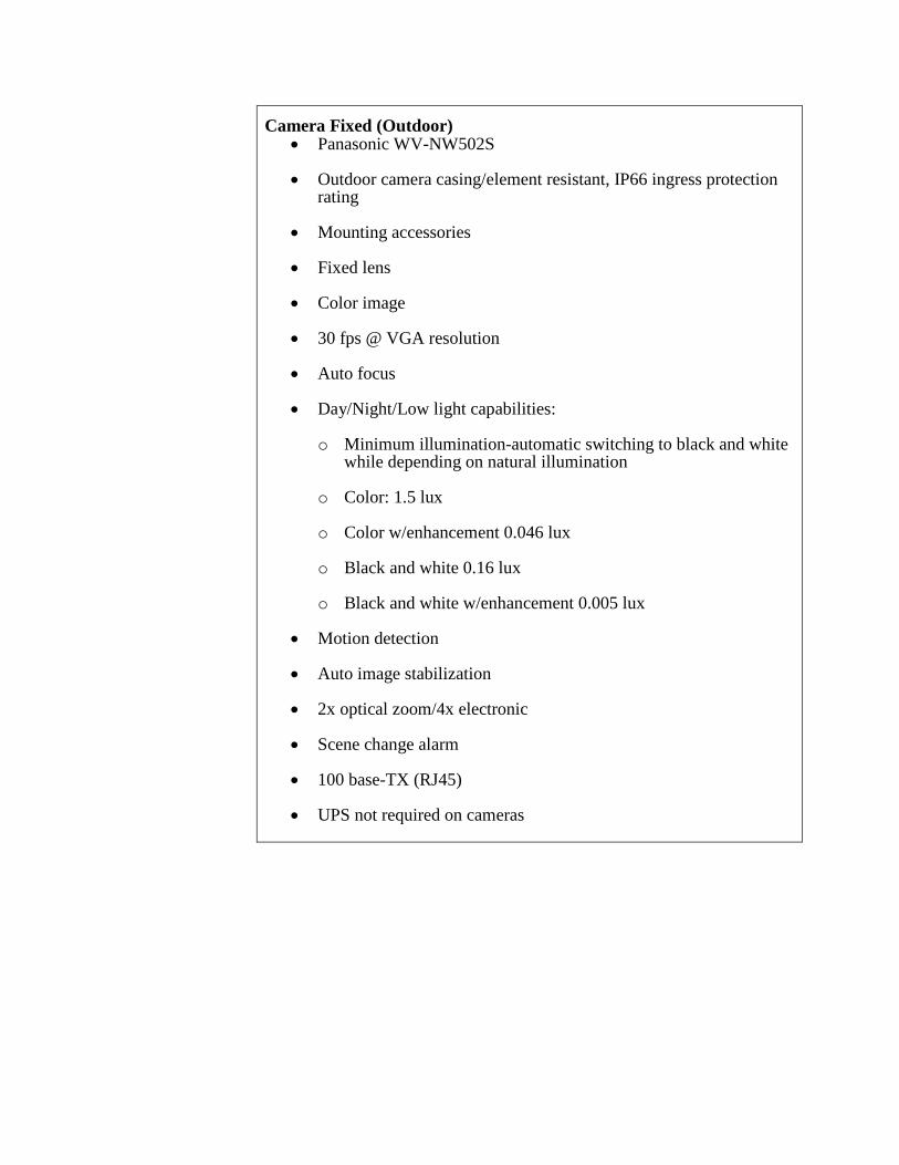
Camera Fixed (Outdoor) • Panasonic WV-NW502S
• Outdoor camera casing/element resistant, IP66 ingress protection rating
• Mounting accessories
• Fixed lens
• Color image
• 30 fps @ VGA resolution
• Auto focus
• Day/Night/Low light capabilities:
o Minimum illumination-automatic switching to black and white while depending on natural illumination
o Color: 1.5 lux
o Color w/enhancement 0.046 lux
o Black and white 0.16 lux
o Black and white w/enhancement 0.005 lux
• Motion detection
• Auto image stabilization
• 2x optical zoom/4x electronic
• Scene change alarm
• 100 base-TX (RJ45)
• UPS not required on cameras
Camera Fixed (Indoor) • Panasonic WV-NF302 • Indoor casing to prevent tampering • Mounting accessories • Fixed lens • Color image • 30 fps @ VGA resolution • Auto focus • Day/Night/Low light capabilities:
o Minimum illumination o Color: 1.5 lux o Color w/enhancement 0.046 lux o Black and white 0.16 lux o Black and white w/enhancement 0.005 lux
• Motion detection • Auto image stabilization • 3.6x optical zoom/4x electronic • 100 base-TX (RJ45) • UPS not required on cameras •
Centrally managed security system with distributed network based video recording system
• AMAG Symmetry Security Management Software-Video modules and camera device licensing.
• AMAG Symmetry Network Video recording software.
• Concurrent AMAG web client licenses.
• Compatible with the City’s existing AMAG security control software and Microsoft SQL MSDE database. The City will provide Microsoft SQL licensing as needed.
• Capable of recording at 15 fps minimum.
• Ability to add cameras and data storage for additional security camera sites.
• The system must integrate seamlessly with the cameras described herein.
• The system must record all video feeds in a standard digital file format for playback compatibility on any desktop or server computer without any special proprietary video player software required.
• Ability to save video file(s) onto portable media (CD-R, DVD-R, flash drive).
• The system must be securely accessible both locally and remotely via the City’s network to search and play back video files and perform administrative functions. No client software install required for web clients.
• Ability to manage all aspects of camera controls and recording.
• Ability to place video storage device either locally or centrally based on configured storage destination.
• Ability to view multiple cameras at a time from both live feed and recorded video.
Control Room NVR server and storage • Dell Poweredge R330 rack server with 5 year warranty.
• Intel Xeon 12403.5GHz, 8M cache, turbo.
• 16.4GB (2x8GB), UDIMM.
• Two 200 GB SSD hard drive (Raid 1).
• PERC H330/H730 (SAS/SATA controller) 2 hard drives Raid 1.
• PERC H330 RAID Controller.
• PERCH830 Raid Adapter for external MD1420.
• On-board dual Gigabit Ethernet.
• DVD-ROM drive.
• Power supply redundant 400W.
• Sliding ready rails with cable management arm.
• Windows Server 2012 R2
• MD1420 power vault with 24 x 2Tb 7.2K rpm NLSAS 12 Gbps 2.5-inch hotplug hard drives, rapid rails for square hole racks.
• Standard power cords for all power supplies, NEMA 5-15p to C13.
• 5 years ProSupport 4HR 7x24 onsite: Non mission critical for all equipment.
• Must record and store video from all cameras for thirteen (13) months of video running 24 hours/day, 7 days/week recording when activated by motion detection. No file archive is required.
Control Room Terminal/Web Server • Dell R330 rack server.
• Intel Xeon 1240,3.5GHz, 8M cache, turbo.
• 16.4GB (2x8GB), UDIMM.
• WindowsServer 2012 R2.
• Windows terminal server license.
• Six terminal server Microsoft terminal server client access licenses.
• Two 200 GB SSD hard drive (Raid 1).
• PERC H330/H730 (SAS/SATA controller) 2 hard drives Raid 1.
• PERC H330 RAID Controller
• PERCH830 Raid Adapter for external MD1420.
• On-board dual Gigabit Ethernet.
• DVD-ROM drive.
• Power supply redundant 400W.
• Standard power cords for all power supplies, NEMA 5-15p to C13.
• Sliding ready rails with cable management arm.
• Five years ProSupport 4HR 7x24 onsite: Non mission critical for all equipment.
SCADA, Controls, and Telemetry Requirements
Facility SCADA System Overview
Facilities and wells shall be designed to allow for automatic operation with remote monitoring and supervision.
Each well will be controlled by a local PLC. All PLCs shall be tied together with the SCADA workstations via a fiber-optic network. Controls of existing Well No. 9 will be modified to interface it to the new facility via fiber-optic cable.
SCADA system shall be Wonderware.
Provisions shall be made allowing the City’s existing SCADA system to access the NTWFP plant SCADA via radio, which shall be compatible with City’s existing
radio system (spread spectrum, serial interface) project SCADA via fiber-optic network, new and existing. The fiber-optic cable demarcation point between the plant site and existing networks shall be a fiber-optic cable pull box near the property line. The location of the demarcation pull box needs to be coordinated with the City. Modifications to the existing City SCADA system are included in this the current project. See Appendix J of Volume III-A for the pre-negotiated Scope-of-Work and fee to be incorporated in to the DB effort.
A design objective is to have all PLCs by Allen-Bradley Logix platform (ControlLogix and/or CompactLogix).
Controls
Controls for manual and automatic equipment operation will be located in the MCC compartment containing switchgear for the respective equipment. Minimum requirements for equipment control are described herein under the section entitled "MCC."
Pumping units operating in the "auto" mode will receive the start/stop and speed signals from the plant control system. PLCs will transmit alarm and status signals from remote locations to the treatment plant SCADA and will receive control signals and set points for pumping unit operation. All alarm, status, and control signal wires will be terminated on a terminal block within the instrument control panel. If the PLC fails, the only mode of pump operation will be manual via the pump HOA switch.
PLC
PLCs will receive all alarm and status signals and all analog signals from field instrumentation. In addition, PLCs will provide output signals to the respective MCC pump starter which will start/stop pumping units and cause pumping unit shutdown under various alarm conditions (e.g., low flow rate, high discharge pressure, and low discharge pressure).
Preferred Manufacturers
The following manufacturers have been preapproved by the City. Any proposed alternatives are subject to City approval:
Equipment Approved Manufacturer Well or booster pump Flowserve, Goulds, Peerless
Pump motor US (no equals)
Propeller flowmeter McCrometer (no equals)
Resilient wedge gate valve Mueller
Butterfly valve Mueller
Air/vacuum valve APCO, Crispin, Val-Matic
Wafer check valve K-F Industries
VFD ABB, Cutler-Hammer
MCC Allen Bradley, Cutler-Hammer, General Electric, Siemens
PLC Allen Bradley (no equals)
E/G unit Caterpillar, Cummins-Onan
Chemical feed pump Prominent, Pulsafeeder
Chlorine residual analyzer Hach (no equals)
Ammonia residual analyzer Hach (no equals)
Signage The Company shall include in its design, the location and types of signage including, but not limited to, entrance sign to the facility, descriptive signs for each building and process, chemical classification and safety signs, plus any required OSHA safety signs, and pipe labeling.
Fire Alarm System
The Company shall provide a plant-wide fire detection and alarm system, with audible as well as visual alarm signals, conforming to the requirements of the local fire marshall, NFPA, and Factory Mutual requirements. Fire extinguishers rated for A, B and C type fires shall be located in all buildings. System shall be connected to SCADA and through the SCADA System, be capable of calling the City’s security service.
Geotechnical Analysis and Recommendation Requirements
The Company shall provide a geotechnical engineering report, which provides specific recommendations for the design and construction of the structures, pipelines, and other facilities proposed by the Company. The geotechnical report shall address the subjects outlined in the
Preliminary Geotechnical Report (Appendix 9), and may utilize data taken from the preliminary report. The Geotechnical Report shall also utilize data obtained from supplementary site exploration and testing performed by the Company, if such data are needed.
The recommendations of the Geotechnical Report shall be used in the design of grading, foundations, backfill, retaining walls, and subgrade remediation. Settlement calculations from the Geotechnical Report shall be used when setting the hydraulic profile and in the design of structures and pipelines. The Geotechnical Report shall address specifically how the risk of seismically induced settlement is to be mitigated. The Report shall be signed by a California licensed geotechnical engineer, and shall be submitted to the City for its review.
Construction Documents (Plans, Specifications, and Equipment Submittals)
The Company shall generate and maintain lists showing the status of the documents. The Company shall generate a drawing list, specification list, and an equipment list and submit to the City monthly.
Six copies of the construction documents shall be submitted to the City, signed and sealed by a registered engineer in the state of California, for review of compliance with codes, regulations and conformance to the contract. The City will review the documents within 30 working days after receipt. Comments, if any, will be provided to the Company. The lack of any comments by the City does not relieve the Company of responsibility for accuracy and content.
Drawings shall be prepared full-size (22” x 34”), but shall be submitted as half-size (11” x 17”), unless full-size is needed for legibility. Drawings shall be prepared using scales that are typical for the type of drawing that is provided. Plan, specifications and equipment submittals shall be submitted to the City at 50% design, 95% design, released for construction stages and record documents. The released for construction and record documents shall be signed and sealed by the Engineer of Record.
No construction activities shall be performed prior to the concurrence and approval that the associated plan, specifications, and equipment submittals have been released for construction.
Design Quality Control and Quality Assurance Requirements
Company shall submit, no later than 30 days after award of contract, six (6) copies of a plan for design QA/QC. Minimum requirements are:
• Who is the QA/QC manager for the project • Provide a log showing review and approval process
• Provide log and description of how design revisions, RFIs, and Shop Drawings are to be tracked, reviewed, and distributed
• Include in the process City review and approval of drawings, drawing revisions, and RFIs.
• Every submittal to the City shall be accompanied by the QC checklists compiled during the Company’s review process.
Equipment Submittal Document
The Company shall submit to the City, drawings, diagrams, schematics of all significant equipment associated with the operation of the project. Those drawings will be reviewed by the City for conformance with the contract. The submittal of these drawings shall precede any submittals of construction documents for plan check. The City will review all equipment submittal documents within 10 working days, and submit comments, if any, related to the drawings. At the completion of construction the Company shall submit to the City, complete set of operations and maintenance manuals which shall include, as a minimum, all certified equipment drawings, descriptive information on the equipment’s operation, maintenance schedules, maintenance instructions and parts list.