C.3 Specifications for the 10XAS-Series 7 C.3.a Power Requirements 7 C.3.b Signal Output 7 C.3.c Physical Characteristics 7 C.3.d Functionality Specifications 8 C.3.e Options Available with the 10XAS-Series 8
The SCAN-A-LINE� Auto-Sync Sensor � 10XAS-Series is a non- contact, electro-optical sensor designed primarily for the edge position detection of strip material edges. Over the years, it has been found to be fully capable of various measurement and guiding applications. The 10XAS-Series sensor is compatible with a variety of SCAN-A-LINE� processing units (typically up to two sensors per processing unit). Because of its versatility and reliability, the 10XAS-Series is one of the most cost effective edge position detection sensor systems on the market today. The Model 10XAAS of the 10XAS-Series is an upgrade to the Model 10XAS, providing improved fluid an easily replaced Lexan® bezel.
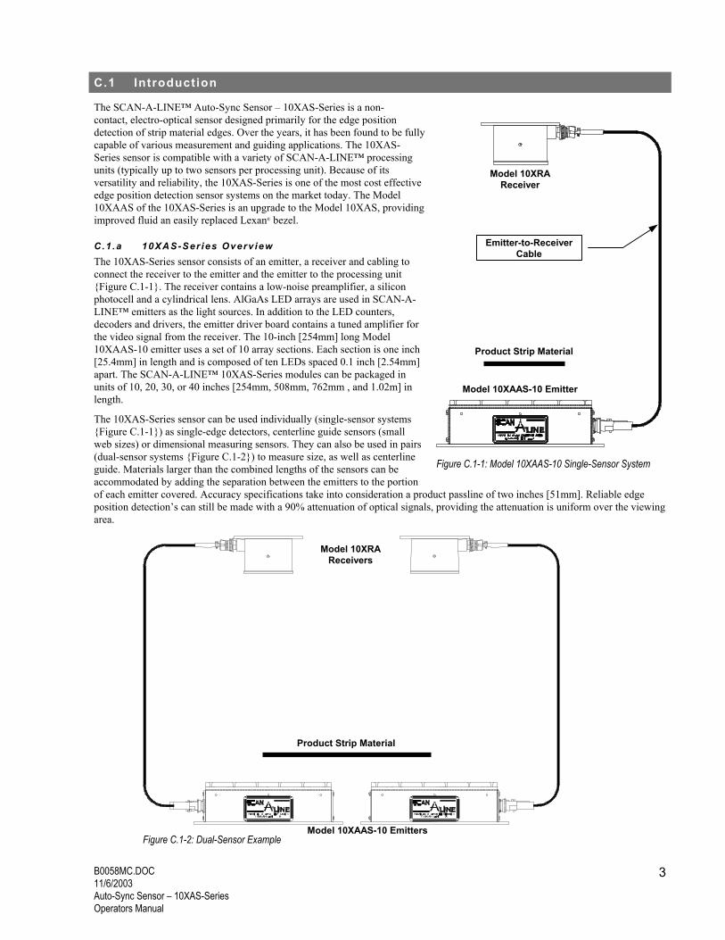
C.1 .a 10XAS-Ser ies Overv iew The 10XAS-Series sensor consists of an emitter, a receiver and cabling to connect the receiver to the emitter and the emitter to the processing unit {Figure C.1-1}. The receiver contains a low-noise preamplifier, a silicon photocell and a cylindrical lens. AlGaAs LED arrays are used in SCAN-A-LINE� emitters as the light sources. In addition to the LED counters, decoders and drivers, the emitter driver board contains a tuned amplifier for the video signal from the receiver. The 10-inch [254mm] long Model 10XAAS-10 emitter uses a set of 10 array sections. Each section is one inch [25.4mm] in length and is composed of ten LEDs spaced 0.1 inch [2.54mm] apart. The SCAN-A-LINE� 10XAS-Series modules can be packaged in units of 10, 20, 30, or 40 inches [254mm, 508mm, 762mm , and 1.02m] in length.
The 10XAS-Series sensor can be used individually (single-sensor systems {Figure C.1-1}) as single-edge detectors, centerline guide sensors (small web sizes) or dimensional measuring sensors. They can also be used in pairs (dual-sensor systems {Figure C.1-2}) to measure size, as well as centerline guide. Materials larger than the combined lengths of the sensors can be accommodated by adding the separation between the emitters to the portion of each emitter covered. Accuracy specifications take into consideration a product passline of two inches [51mm]. Reliable edge position detection�s can still be made with a 90% attenuation of optical signals, providing the attenuation is uniform over the viewing area.
Figure C.1-1: Model 10XAAS-10 Single-Sensor System
Figure C.1-2: Dual-Sensor Example
Model 10XRA Receivers
Model 10XAAS-10 Emitters
Product Strip Material
Model 10XRA Receiver
Model 10XAAS-10 Emitter
Emitter-to-Receiver Cable
Product Strip Material
B0058MC.DOC 11/6/2003
Auto-Sync Sensor � 10XAS-Series Operators Manual
4
When used in dual-sensor systems, the 10XAS-Series emitters will �Auto-Synchronize� when power is applied, eliminating the need for primary and secondary emitters. The 10XAS-Series emitters are functionally the same as the older, 10X-Series emitters, although the latter are unable to �Auto Sync� when incorporated into a system. An upgrade is available to convert 10X-Series emitters to auto-sync capability. Contact Harris Instrument Service for more information on upgrading 10X-Series sensors.
C.1 .b Funct iona l Descr ip t ion Each SCAN-A-LINE� 10XAS-Series sensor (emitter, receiver and cabling) operate as a complete position sensing sub-system. The emitter driver board in the emitter, containing a tuned amplifier, employs a 2mHz crystal oscillator and a series of counters, decoders and drivers that generate a signal to light LEDs one through ten {Figure C.1-4}. Every time ten sequential diodes are lighted, a pulse is sent to the LED array boards to advance their counters. The array boards also contain counters that are decoded and used to select LED block 10, 20, 30, etc. At the 100th counted pulse (the end of a ten inch [254mm] emitter LED array board), LED array board #1
is turned off. The last diode triggers the same sequence in the next board if more than one array board is used (a Model 10XAAS-20 has two LED array boards, a Model 10XAAS-30 has three LED array boards, etc.). When the last diode in the last board is turned off, a reset pulse is sent back to the emitter driver to generate the SYNC pulse, reset all counters, and begin the LED lighting sequence again. The scanning direction is from the two-connector end of the emitter to the other end of the emitter.
The receiver is positioned to �see� each diode in the emitter array as it is lit. A cylindrical lens in the receiver gathers light from each of the emitter LEDs and focuses it onto one or more silicon cell(s) {Figure C.1-5}. The emitter LED light focused by the receiver lens onto the photocells generates an electrical current. Because the light from the emitter LEDs in the array is pulsed at a 20kHz rate, the current generated in the receiver is modulated at the same frequency. The receiver preamplifier is tuned to this frequency (20kHz) to help reject signals generated by other sources of light.
Because the light is not actually imaged onto the photocell, placement of the receiver in standard systems is rather non-critical, although in several circumstances (detection of clear materials, end alignment of the receiver, small emitter-to-receiver separation), the positioning of the receiver can be very important. Since the light from each of the emitter diodes is emitted in the form of an expanding cone rather than a beam, it is possible to detect the attenuation of a particular diode by an object long before it completely blocks the light. It is important to note that the edge position is a statistical analysis of the receiver LED detection signal. The amplified signal from the receiver is sampled in the emitter at the peak of each LED pulse. The resulting signal is sent through a low-pass filter into a peak detector and comparator circuit. Whenever the filtered sampled video signal drops to a level equal to one-half the peak level, the comparator outputs a +12VDC signal. This output is buffered and sent from the emitter as the output VIDEO signal. By using sample-and-average techniques, the position of the object with respect to the array can be determined to a resolution 10 or 20 times finer than the spacing between the diodes in the array. The resolution of the system is related to and limited by the diode-to-diode uniformity and the signal-to-noise ratios of the receiver photocell amplifiers.
When the video signal is received in the processing unit, it is translated to the position or measurement information and can be
Figure C.1-4: Model 10XAAS-10 Emitter Interior Views
converted into an analog signal by an analog output device for processing and/or routing to the customer process controlling equipment. A simple processing unit counter can also be used to determine if the proper number of edges have been sensed. In a single-edge application (typically a dual-sensor system, as each sensor only detects one edge), the lack of an edge transition or the presence of more than one edge indicates a sensor FAULT event. The video signal is then converted into an analog signal by the processing unit with an analog output device.
The SCAN-A-LINE� 10XAS-Series receivers are to allow a uniform wide angle view of the emitter. When using a pair of 10XAS-Series sensors with a large measurement or centerline guiding system, it is important to insure that the light from one emitter is not seen by the other receiver. This is most easily accomplished by using a small sheet metal �blinder� to block light coming from the opposite emitter {Figure C.1-6}[Section C.4.f]. Several types of blinders are available for the 10XAS-Series receiver; please contact Harris Instrument Corporation for more information.
C.1 .c Sensor Ba lanc ing All SCAN-A-LINE� 10XAS-Series sensors are computer balanced for optimum performance of the emitter LED�s. Because of the slight differences in intensities of the AlGaAs light emitting diodes in the emitter, the emitter and receiver are individually tested for the light intensity that reaches the receiver photocell. Also, the linear distance between the receiver photocell and the emitter LEDs varies across the entire range of the sensor. To achieve optimum sensor performance, a computer �evens� out the individual LED outputs and stores the results (the sensor balance) in the on-board Erasable Programmable Read-Only Memory (EPROM) chip {Figure C.1-4}.
Balancing of the sensor must be performed at the factory by Harris Instrument Corporation trained personnel (the Service Department can also balance sensors in the field on service calls when necessary). Balancing of the sensor requires the information on the separation between the emitter and the receiver, as well as the alignment of the receiver over the emitter and possibly the product passline spacing. Unless specified when ordered, ALL 10XAS-Series sensors are balanced at the recommended emitter-to-receiver separation and the receiver in the center aligned position (the receiver centered over the middle LED of the emitter) {Table C.1-1}.
NOTE: Any time the receiver(s) and/or emitter(s) physical positioning changes, the sensor MUST BE
REBALANCED. Contact Harris Instrument Corporation Service for information on balancing the sensor(s).
The 10XAS-Series is highly resistant to most of the industrial environments that can cause problems with edge sensing equipment. The operating temperature for the 10XAS-Series is 32°F to 122°F [0°C to 50°C]. Operations outside this range are possible with special provisions made to protect the equipment, such as heat shields and water jackets.
A reasonably uniform buildup of dust, dirt or oil will not affect the operation or accuracy of a SCAN-A-LINE� sensor. Dust, dirt and oil build-up can attenuate the sensor signal by over 90% before any loss of accuracy occurs. Large pieces of material or opaque coatings of paint or heavy grease can completely block the beam or attenuate it below tolerable limits. To avoid erratic readings or maintenance difficulty, care should be taken to install the emitter and receiver where the danger of such contamination is minimized. A simple air wipe installed over the emitter window can be helpful where contamination cannot be avoided.
Since sensing an edge position is a factor of time and not of signal amplitude with SCAN-A-LINE� sensors, vibration is of little or no consequence. In very high vibration applications, simple vibration dampening will solve most vibration problems encountered.
Because the 10XAS-Series is producing and looking for light modulated at approximately 20kHz, it is unlikely that most ambient light sources will be a problem. It is best to avoid placing a direct light source in the receiver view path. A bright light source can overload the receiver photocell and prevent it from detecting the emitter light. When special conditions require them, special filters can be provided to reduce the problem. Special filters are also required when measuring incandescent, hot worked metals to remove the infrared spectrum energy.
Even though the 10XAS-Series sensor is tolerant of most ambient light situations, high-intensity strobe lights can also cause receiver cell overload, producing false detection�s. Because of the high frequency pulsing of strobe lights, the receiver can interpret the strobe pulses as an extra edge or trigger a sensor FAULT detection. Care should be taken when installing the 10XAS-Series sensor to locate the sensor as far as possible from any strobe light(s). If operational constraints require that the SCAN-A-LINE� sensor be mounted in close proximity to a strobe light, horn blinders [HBLD Option � Section C.6 {Figure C.2-1}] are available for 10XR-Series receivers that may assist in preventing strobe or reciprocating light interference.
In applications where the sensor may be exposed to mechanical damage, the receiver and emitter are available in ULTRA-TOUGH� enclosures − UT Option. ULTRA-TOUGH� enclosures are designed to withstand most industrial conditions.
Power for the 10XAS-Series sensor must be supplied by a SCAN-A-LINE� processing unit, with up to two sensors per processing unit. The tolerance for power on the 10XAS-Series is very good, but the voltage MUST BE STABLE.
Model Name Description Function Model DCPU Digital Processing Unit Strip position control Model GPU General Processing Unit Sensor power & analog output Model PCPU PID Control Processing Unit Strip position control Model TCPU Time Proportional Control Processing Unit Strip position control Model UCPU Universal Control Processing Unit Rewind strip control Model UMPU Universal Measurement Processing Unit Strip measurement Model MPPU Multi-Purpose Processing Unit Strip measurement Table C.3-1: 10XAS-Series Sensor Compatible Processing Units
A good system earth ground is essential in reducing the possibility of interference from other electrical equipment. Care should be taken to insure that the SCAN-A-LINE� earth ground is separate from the grounds used by other electrical systems. This is most important when high current (i.e., welding equipment) and high voltage is involved.
C.3 .a Power Requi rements Power Supply (rated at 50°C):
+12VDC ±0.25VDC @ 250mA -12VDC ±0.25VDC @ 50mA
C.3 .b S igna l Output The output signal from the 10XAAS sensor is a 12VDC CMOS signal that goes to the logic high state any time the emitter light is detected by the receiver. The position of edges and number of edges encountered by the sensor during a scan can be determined by observing the output signal from the emitter. Signal output is the same whether using the sensor for edge guiding, centerline guiding or dimensional measurement. Figure C.3-1 shows the receiver signal as viewed on an oscilloscope when an Alignment Adapter Model AA10X [Section AA] is attached to the sensor system.
C.3 .c Phys ica l Character is t ics The 10XAS-Series emitter measures 4.125 inches [105mm] tall by 3 inches [76mm] wide in lengths from 14.2 inches [361mm] (Model 10XAAS-10) to 44.2 inches [1123mm] (Model 10XAAS-40). It is constructed of extruded aluminum tube for the housing with an rolled aluminum base plate and a machined aluminum bezel mounting plate with a Lexan® bezel as the emitter window. The emitter cable is attached to the emitter with a seven-pin MS-style circular connector. The receiver measures 6.6 inches [168mm] long by 3 inches [76mm] wide by 3.6 inches [91mm] tall. It is constructed of a cast aluminum housing with extruded aluminum mounting plate and bezel containing the borosilicate glass viewing window. The receiver pigtail cable (section one) for the Model 10XRA receiver is wired via a 6-pin connector to the receiver process board and is routed through a ½ inch [12.7mm] IMC conduit fitting. This cable attaches to a receiver extension cable (section two) and the other end of the receiver extension cable connects to the emitter with a 6-pin MS-style circular connector.
The 10XAS-Series emitter and receiver are also available in ULTRA-TOUGH� enclosures (Model 10XAS-UT) for high collision environments). The ULTRA-TOUGH� emitter measures 4.5 inches [114mm] tall by 4 inches [102mm] wide in lengths from 16 inches [406mm] (Model 10XAS-10-UT) up to 46 inches [1168mm] (Model 10XAS-40-UT). The emitter is constructed of cast aluminum housings over 0.625 inches [159mm] thick, a rolled aluminum bezel 0.75 inches [191mm] thick with a borosilicate glass emitter window approximately 0.375 inches [95mm] thick. The ULTRA-TOUGH� receiver measures 8 inches [203mm] long by 4 inches [102mm] wide by 4.6 inches [117mm] tall. They are also constructed of cast aluminum housings with aluminum bezels and borosilicate glass viewing windows similar to the ULTRA-TOUGH� emitters. Included with the Model 10XAS-UT sensors is a 20 foot [6.1m] watertight emitter cable and a 15 foot [7.6m] watertight receiver cable. All cable connections for the ULTRA-TOUGH� are identical to the standard 10XAS-Series sensor, except for the use of the watertight connectors that attach in the same fashion as standard connectors (standard and sealed connectors are interconnectable).
Figure C.3-1: Oscilloscope Output of 10XAS-Series Sensor
C.3 .d Funct iona l i ty Spec i f ica t ions The following specifications {Table C.3-2} for the 10XAS-Series sensors are based upon a Model 10XAAS-10 emitter with standard LEDs detecting an opaque material at an emitter-to-receiver separation of twenty inches [508mm] with a product passline of three inches [76mm]. Operating conditions are optimal (no ambient light interference, 25°C operating temperature, proper alignment, etc.) for the sensor and processing unit. Receiver is center-aligned. All specifications are obtained by operating with a Multi-Purpose Processing Unit (Model MPPU) that is capable of 12-bit resolution. Actual sensor performance may vary depending upon application conditions and processor capabilities (IR LEDs, detecting clear, translucent or loosely woven materials, improper alignment, extended separation and/or passline spacing, etc.).
Specification Value Accuracy ±0.005 inches [±0.127mm] Repeatability ±0.005 inches [±0.127mm] Reproducibility ±0.010 inches [±0.254mm] Stability Better than ±0.005 inches [±0.127mm] Linearity ±0.024 inches [±0.61mm] standard at 2-sigma
±0.016 inches [±0.41mm] enhanced at 2-sigma ±0.03125 inches [±0.794mm] at 2-sigma length measurement
Table C.3-3: 10XAS-Series Sensor Specifications
C.3 .e Opt ions Ava i lab le for the 10XAS-Ser ies The 10XAS-Series is available in several optional configurations to meet a variety of application requirements. The emitter and the receiver may be housed in the standard aluminum housings or in the ULTRA-TOUGH� enclosures. The connections between the emitter and receiver are by flexible electrical cable. Please review the Configuration Checklist (page iv) for the specific options ordered with your system. The various options and configurations are specified as follows:
Option Description 10XRA Designates a 10XAS-Series receiver. 10XRA-UT Designates a 10XAS-Series receiver housed in the ULTRA-TOUGH� enclosures. CLR Designates that the emitter is configured for the Clear Materials Option. Installation and setup of the
sensor is modified as per Section C.5.b. BLD Indicates that the unit is configured with long blinders. These blinders are typically used only with dual-
sensor systems and are supplied at no extra charge. HBLD Indicates that the unit is configured with horn blinders. These blinders are used with systems that will be
installed in lines that may have interference from strobe or other pulsing light sources. LRR Long Range Receiver for extended emitter-to-receiver separations. POL Indicates the sensor is protected with polane painted surfaces and stainless steel screws to resist
corrosion (included with the UT Option at no extra charge). Improves corrosion resistance. XCB Indicates that the cables supplied with the system are longer than the standard cables (15 feet [4.6m] to
20 feet [6.1m] up to 50 feet [15.2m]). Table C.3-4: Options available for 10XAS-Series sensors
The 10XAS-Series sensor is designed for operation with almost all the SCAN-A-LINE� processing units (see Table C.3-1). Each application may have slightly different installation requirements. The three basic applications for 10XAS-Series sensors are:
Edge Guiding or Control Centerline Guiding or Control Measurement When installing the 10XAS-Series sensor, some commonsense procedures to protect the sensor from any line collision should be taken. Damage to sensors from line collisions is the primary cause of SCAN-A-LINE� sensor failures. Install the sensor in a position on the line where it is protected as much as possible from strip collisions. Many times, a simple deflection bar or plate mounted above the sensor components will prevent such collisions. Once properly installed and protected, the 10XAS-Series sensor will provide a lifetime of reliable operation.
NOTE: If any welding is to be performed near the 10XAS-Series sensor,
COVER THE VIEWING WINDOW with a protective material (i.e., metal plate, wood sheet, etc.) to prevent the welding flash from
coming in contact with the Lexan® bezel or the glass in the window. Such welding flash is hot enough to melt the viewing window causing
pitting of the window that shows up as incorrect readings.
C.4 .a Bas ic Ins ta l la t ion Guide l ines The 10XAS-Series emitter and receiver are typically mounted parallel with the receiver directly above the center of the emitter unless otherwise specified [Section C.4.c]. The centerline of the emitter and receiver should be perpendicular to the strip, with a suggested tip of less than ±5°. The wedge of light from the emitter is approximately 30° wide. The receiver lens has a more narrow angle and may require mounting adjustment. A greater emitter-to-receiver spacing increases the requirement for proper aim adjustment {Figure C.4-1}.
Emitter-to-Receiver Separation Emitter-to-receiver spacing for the 10XAS-Series is generally one-and-one-half times the emitter length up to seventy-two inches [1829mm]{Figure C.4-2 and Table C.4-1 next page}. This offers well-balanced receiver viewing sensitivity. The optimum emitter-to-receiver separation depends upon the length of the emitter and several other factors. Close emitter-to-receiver separation will limit the inspection range of the sensor and may cause a loss of sensitivity at the outside edges when long emitters are used. Although ambient light sources are largely rejected by the 20kHz tuning of the video signal processing circuits and the IR filtering in the silicon cells, some interference may be experienced. Strobe lights or any pulsed IR light source can pose special problems for the 10XAS-Series sensor. Shielding the receiver from interfering light sources to reduce such ambient light interference will improve performance [such as horn blinders � Section C.??].
1 ½ Times Emitter Length Minimum up to 72 inches [1829mm]
B0058MC.DOC 11/6/2003
Auto-Sync Sensor � 10XAS-Series Operators Manual
10
NOTE: Unless specified by the customer (or dealer representative) at time of purchase, ALL 10XAS-Series
sensors are computer balanced for emitter-to-receiver separations at recommended separation for that size of sensor [Section C.1.c].
Lateral Strip Deviation The dynamic measurement range for the 10XAS-Series varies depending upon the length of the emitter. However, operational considerations, such as lateral strip deviation {Figure C.4-3} and product passline (distance from the emitter face to the strip bottom face) can lessen that range {Figure C.4-4}. The 10XAS-Series sensor should be placed on the line where the strip lateral position deviation is relatively stable to prevent loss of range caused by such deviation. Typically, the detection range is approximately two inches [50.8mm] less than the length designation of the sensor (i.e. a 10XAAS-10 sensor will have a range of eight inches [229mm]) to allow for unavoidable lateral strip deviation.
NOTE: Larger emitter-to-receiver separations and product passlines are available with special configurations for the 10XAS-Series sensor. Please contact Harris Instrument Corporation for more information on
extended separations and larger or smaller passlines.
Product Passline Product passline is the position deviation of the strip in relation to the emitter face {Figure C.4-4}. Product passline spacing for the 10XAS-Series is recommended at one inch [25mm] minimum up to 1/3 emitter-to-receiver spacing maximum, with optimal spacing of two inches [51mm] to four inches [102mm] typical {Figure C.4-4}. Product passline deviation should be kept at a minimum (i.e. no changes in product passline greater than 0.25 inch [6mm]) with center-aligned receivers on 10XAS-Series sensors (note that centerline guiding applications are less susceptible to product passline deviation). As the product passline increases the active inspection range of the sensor decreases, so any passline spacing greater than four inches [102mm] may cause a loss of overall sensor inspection range.
NOTE: When used for measurement and/or edge guide applications, the product passline must be stable. Any change in product passline may cause inaccurate position or measurement readings. Contact Harris
Instrument Corporation for more information on varying product passline. C.4 .b Emi t ter Pos i t ion ing The positioning of the emitter(s) in a 10XAS-Series sensor system is, as described in Section C.4.a, typically one inch [25mm] to 1/3 of the emitter length below the strip, with two inches to four inches [51mm to 102mm] the recommended product passline {Figure C.4-4}. The emitter lateral positioning should typically be with the emitter connectors facing outward from the centerline of the strip {Figure C.4-5}.
Because of physical constraints of the installation (not enough side-to-side room under the line), the connectors can be faced inwards {Figure C.4-6}. Note that on installations with First Edge Detection [Section AC], this configuration may not be applicable. Review Section AC, if applicable, to determine the proper emitter positioning for such installations.
Figure C.4-3: Strip Lateral Deviation Example
Figure C.4-4: Nominal Passline Specification
Lateral Strip Deviation
Strip Direction
Recommended Product Passline Spacing: 1" [25mm] to 1/3 Emitter-to-Receiver Separation Max. 2" [51mm] to 4" [102mm] Recommended
NOTE: First Edge Detection systems [Section AC] may REQUIRE
that the 10XAS-Series connectors be facing outwards from the centerline of the line
for proper operation. C.4 .c Rece iver Pos i t ion A l ignment The receiver for the 10XAS-Series sensor is typically mounted, faces parallel, with the receiver photocell directly over the center-point (or mid-point) of the emitter {Figure C.4-6}. This position allows for the best �view� of the all the emitter LEDs by the receiver. All SCAN-A-LINE� sensors are configured and the sensor balanced with a center-aligned receiver unless otherwise specified by the customer or the application.
But like the entire SCAN-A-LINE� product line, the 10XAS-Series sensor is very flexible. Different applications may require a receiver position that varies from the typical center-aligned positioning.
Applications such as thickness independent width or dynamic cut-length measurement as well as thickness independent edge guiding with 10XAS-Series sensors [Section C.5.c] require alignment of the receiver photocell above the outside-end LED (connector end) of the emitter. In the same fashion, length measurement with 10XAS-Series sensors [Section C.5.a] requires end-alignment of the receiver, but over the opposite end of the emitter from the connectors with the connectors facing inwards. The reason for these alignment configurations is so the receiver will always see the bottom edge of the strip. If the receiver detects the top edge of the strip, measurement and edge guiding applications are adversely affected by the strip thickness.
Receiver Positioning � Center Alignment The following procedure will assist in the positioning of the receivers for center-aligned 10XAS-Series sensor configurations.
1) Determine the mid-point of the emitter LED array {Figure C.4-8}. If not already marked from the factory, mark this point of the emitter housing side 1.15 inches [29mm] from the emitter face.
2) Fixture the emitter(s) on the line in the position required for detection of the strip (maximum & minimum). a) For a single-sensor centerline guiding installation, find the centerline of the mill and position the mid-point of the emitter LED array directly on the mill centerline [Section C.4.c]. b) For a single-sensor edge guide application, find the median edge position of the strip(s) and mount the emitter so the mid-point of the emitter LED array is directly aligned with the centerline of the median strip material(s) edge position [Section C.4.d]. c) For a dual-sensor centerline guiding installation, find the centerline of the mill and position the mid-point of the emitter-to-emitter separation directly aligned with the centerline of the mill [Section C.4.e].
3) Determine the mid-point of the receiver photocell {Figure C.4-9}. If not already marked from the factory, mark this point on the receiver housing side approximately 1.7 inches [43mm] from the receiver face.
4) Using a plumb line, measure from the mid-point of the receiver photocell array to the emitter face the total emitter-to-receiver separation (typically one-and-one-half times the emitter length up to 72 inches [1829mm]). Locate the mid-point of the receiver photocell array at the point where the receiver photocell mid-point is directly over the emitter LED mid-point.
5) Fixture the receivers in this position with the receiver face parallel to the emitter face with a tolerance of ±5°.
Figure C.4-8: Emitter LED Mid-point for Model 10XAAS-10 Emitter
Figure C.4-9: Receiver Photocell Mid-Point for Model 10XRA Receiver
1.15" [29mm]
7.10" [180mm]
6.00" [152mm]
6.20" [158mm]
Model 10XAAS-10 Emitter Top View
Model 10XAAS-10 Emitter Side View
Mid-Point ofEmitter LED
Array
Mid-Point of Emitter LED
Array
1.50" [38mm] 1.50"
[38mm]
Dimensions Listed Here for Model 10XAAS-10 Emitter ONLY
2.00" [51mm]
2.00" [51mm]
2.30" [58mm]
1.70" [43mm]
Mid-Point of Receiver
Photocell Array
Mid-Point of Receiver
Photocell Array
Model 10XRA Receiver Top View
Model 10XRA Receiver Side View
Dimensions Listed Here for Model 10XRA Receiver ONLY
Receiver Positioning � End Alignment The following procedure will assist in the positioning of the receivers for end-aligned Model 10XAAS sensor configurations typically used for thickness independent operation.
1) Determine the mid-point of the emitter end LED {Figure C.4-10} nearest to the connectors (typically the end of the emitter facing the outer side of the line). If the emitter connectors are to face inward towards the centerline of the strip, determine the mid-point of the opposite emitter end LED. If not already marked from the factory, mark this point on the emitter housing side approximately 1.15 inches [29mm] from the top of the emitter face.
2) Fixture the emitter(s) on the line in the position required for complete detection of the strip (maximum & minimum). a) For a single-sensor centerline guiding or measurement installation, find the centerline of the mill and position the mid-point of the LED array directly aligned with the centerline of the mill [Section C.4.d]. b) For a single-sensor edge guide application, find the median edge position of the strip and position the emitter so the mid-point of the emitter is directly aligned with the centerline of the median size strip material [Section C.4.e]. c) For a dual-sensor centerline guiding or measurement installation, find the centerline of the mill and position the mid-point of the emitter-to-emitter separation directly aligned with the centerline of the mill [Section C.4.d].
3) Determine the mid-point of the receiver photocell {Figure C.4-9}. If not already marked from the factory, mark this point on the receiver housing side approximately 1.7 inches [43mm] from the receiver face.
4) Using a plumb line, measure from the middle of the emitter end LED up to the receiver face the total emitter-to-receiver separation (typically one-and-one-half times the emitter length up to 72 inches [1829mm]). Locate the mid-point of the receiver photocell array at the point where the receiver photocell mid-point is directly over the mid-point of the emitter end LED.
5) Fixture the receivers in this position with the receiver face parallel to the emitter face.
6) Tilt the receiver on the receiver photocell array mid-point until the mid-point of the receiver photocell points directly at the emitter middle LED. Tighten the receiver fixture in place with a tolerance angle of -2°/+5°.
C.4 .d S ing le -Sensor Ins ta l la t ion Single-sensor installation of 10XAS-Series sensors is relatively straight forward. The emitter should be placed below the strip at an optimal product passline of two inches [50.8mm] to four inches [102mm] {Figure C.4-4}. The receiver should be mounted directly over the centerpoint of the emitter in applications where material thickness does not exceed 1/16th of an inch [1.6mm] {Figure C.4-7}. In cases of variable thickness materials or materials thicker than 0.0625 inch [1.6mm], see Section C.5.c.
The field-of-view for a single-sensor application is defined by the last LED on each end of the emitter as the base of a triangle to the receiver photocells as the apex of the triangle {Figure C.4-11}. Though the sensor can detect material edges anywhere within this field of view, dynamic range is reduced as product passline increases.
Figure C.4-10: Emitter End LED Location for Model 10XAAS-10 Emitter ONLY
Figure C.4-11: Typical Single-Sensor Field of View
Dimensions Listed Here for Model 10XAAS-10 Emitter ONLY 1.04" [26mm]
4.95" [126mm] 1.15"
[29mm]
2.15" [55mm] 4.95" [126mm]
1.25" [32mm]
1.50"[38mm]
1.50"[38mm]
Emitter End LED Mid-points
Emitter End LED Mid-point
Sensor Field-of-
View
Model 10XRA
Receiver
Model 10XAAS-10 Emitter
B0058MC.DOC 11/6/2003
Auto-Sync Sensor � 10XAS-Series Operators Manual
14
Edge Guide Applications In edge guide applications, only one edge of the strip should be located over the emitter. This edge should ideally be located over the centerpoint of the emitter {Figure C.4-12} with the median size strip material. This allows lateral strip deviation to vary over the entire range of the sensor. The single edge position information is then routed to the system processing unit for position calculation and control of the strip.
Centerline Guide Applications Centerline guide applications can utilize a single-sensor system when material sizes are small and product passline is relatively little. Typically, the material sizes to be centerline guided must be at least two inches [51mm] narrower than the emitter length (i.e. if the emitter is a Model 10XAAS-30, then material sizes should not exceed 28 inches [711mm]), though product passline can affect the measurement). The emitter typically should be located below the strip with the optimal centerline of the emitter LED array aligned with the centerline of the mill {Figure C.4-13 previous page}. The sensor in a centerline guide application will be attempting to detect two edges. The two edge positions are then routed to the system
processing unit for calculation of the strip position and correction of the centerline position if necessary.
Measurement Applications Measurement applications are almost identical to centerline guide applications, though they can deal with either the width of the material or its length [Section C.5.a]. Typically, the material sizes to be measured must also be at least two inches [51mm] smaller than the emitter length, though the application may reduce material size. The emitter is typically located below the strip with the optimal centerline of the emitter LED array aligned directly with the centerline of the mill. The sensor in a single-sensor measurement application will attempt to detect two edges. The two edge positions are then routed to the system
processing unit for calculation of the material size and for possible routing to a control processing unit (Models PCPU, TCPU or UCPU) for centerline or edge position control.
NOTE: With edge guide and measurement applications, it is important that the sensors be located on the line
where product passline (distance between the emitter and the product) DOES NOT FLUCTUATE. Centerline guiding and control applications are not greatly affected by variations in product passline.
C.4 .e Dua l -Sensor Ins ta l la t ion When the material sizes exceed 38 inches [965mm], generally a dual-sensor system is needed. A dual-sensor system allows for the centerline guiding or measurement of materials up to an almost unlimited size. The main concern with a dual-sensor system is the variation of material sizes. For example, if with a width measurement application the line sometimes runs 34 inch [864mm] wide strips and other times runs 72 inch [1829mm] wide strips, the sensor system must be able to detect both strip widths (for this example, a dual-sensor Model 10XAAS-40 system must be used). The size of sensors and the emitter-to-emitter separation of this dual-sensor system has already been determined upon the purchase of the dual-sensor system.
Emitter A mid-point to emitter B mid-point spacing is based on the following formula:
S=[(W-N)/2]+N
S = Emitter A mid-point to Emitter B mid-point spacing W = Maximum Material Size N = Minimum Material Size
The emitters in a dual-sensor systems should be placed below the strip at a passline typically no greater than six inches [152mm], with two inches [51mm] to four inches [102mm] optimal {Figure C.4-4}. The receiver should be mounted directly over the centerpoint of the emitter in applications where material thickness does not exceed 1/16th of an inch [1.6mm] {Figure C.4-7}. In cases of variable thickness materials or materials thicker than 0.0625 inch [1.6mm], see Section C.5.c.
Figure C.4-12: Typical Neutral Strip Edge Position for Edge Guide Application
Figure C.4-13: Typical Neutral Strip Position for Centerline Guiding or Measurement Applications
The field of view for a dual-sensor application is defined by the last LED on each end of each emitter as the base of a triangle to the receiver photocell as the apex of the triangle {Figure C.4-14}. Though the sensor can detect material edges anywhere within these fields of view, usable inspection range is affected by extended product passlines. Refer to Section C.5.a for information on length measurement dual-sensor installations.
C.4 . f B l inder Adjustment In dual-sensor system installations, the physical geometry of the set-up may require the use of receiver blinders to prevent one receiver from viewing the light produced by the other emitter. These blinders are sheet metal tabs mounted to the face of each receiver. They must be adjusted to their final positions once the system is fixtured on-line.
The easiest way to determine whether or not a receiver is viewing the other emitter in a dual-sensor system is to connect a DC voltmeter to the appropriate �VIDEO� signal in the processing unit. The following steps outline the procedure:
NOTE: The voltmeter will integrate the digital signal produced by the sensor and read 12VDC (11.6 to 12.4,
depending on power supply voltage) when the emitter is fully UNCOVERED and will read 0VDC when the emitter is completely COVERED.
1) Locate the terminal strip connectors for the signals VIDEO A and VIDEO B in the processing unit used with the dual-sensor system. (Refer to the Operators Manual of the appropriate processing unit for the exact location of the terminal strip connectors.). 2) Connect the voltmeter to one of the VIDEO signals. To determine which sensor is being viewed, cover one of the emitters completely and check to see which VIDEO signal is at 0VDC. This sensor will be referred to as Sensor A, and the other as Sensor B, for the remainder of this adjustment procedure. 3) Uncover the emitter and check to see that the DC voltmeter reads 12VDC (11.6VDC to 12.4VDC). If the voltage is not within limits, check the alignment between the Receiver A and the Emitter A and proceed to Step 4. 4) Cover Emitter A and check whether the voltage goes to 0VDC. If any voltage is present, adjust the blinder on Receiver A until a reading of 0VDC is displayed. This will ensure that no light from Emitter B affects Receiver A. 5) Now uncover Emitter A again and check that the voltage reading is 12VDC and that no light from Emitter A is being blocked by the blinder. 6) Repeat steps 3 through 5 for the other sensor (Sensor B) after the voltmeter is connected to the other VIDEO signal. This completes the blinder adjustment procedure.
Figure C.4-14: Typical Centerline or Width Measurement Dual-Sensor Field of View
Sensor BField-of-
View
Sensor A Field-of-
View
Model 10XRA Receivers
Model 10XAAS-10 Emitters
B0058MC.DOC 11/6/2003
Auto-Sync Sensor � 10XAS-Series Operators Manual
16
C.4 .g Cab le Connect ions No matter which application the sensor is targeted for, the sensor connects to the processing unit in the same fashion. Single-sensor systems connect to the top-right circular bulkhead on the bottom panel of the processing unit. Dual-sensor systems connect one sensor (Sensor A) to the top-right circular bulkhead and the second sensor (Sensor B) to the bottom-right bulkhead {Figure C.4-15} on the bottom panel of the unit.
1) Connect the receiver cable female 6-pin MS-style Inline circular to the receiver circular bushing connector and tighten securely.
2) Connect the male connector end of receiver extension cable to the emitter via the 6-pin MS-style circular bulkhead and tighten securely {Figure C.4-16}. Repeat steps 1 and 2 above on the second sensor for a dual-sensor system.
3) If the application is a single-sensor system, connect the emitter cable with the female 7-pin MS-style circular connector to the emitter 7-pin MS-style circular bulkhead. Then connect the male 7-pin MS-style circular connector to the upper-right 7-pin MS-style circular bulkhead on the bottom panel of the processor and tighten securely {Figure C.4-15}.
4) For a dual-sensor application, perform step three for Sensor A. Repeat the procedure for Sensor B, except connect the male 7-pin MS-style circular connector end of Sensor A emitter cable to the lower-right 7-pin female MS-style circular bulkhead on the bottom panel of the processing unit and tighten securely.
Figure C.4-15: Emitter Connections to Processing Unit
The installation of SCAN-A-LINE� 10XAS-Series sensors may have extra requirements that are dependent upon the application. Clear materials (CLR Option), thick materials and length measurement all have specific requirements when installing the sensors.
C.5 .a Length Measurement Length measurement systems that utilize 10XAS-Series sensors in conjunction with the Model MPPU require special installation considerations. The following table details some of the specifications for using 10XAS-Series sensors with length measurement systems.
Specification Value Sensor Type 10XAS-Series Dual-Sensor Material Length Variability 1 60" [1524mm] 1 Minimum Part Length 12" [305mm] Minimum Spacing Between Parts ½" [13mm] Maximum Line Speed 2 150'/minute [45.7m/minute] 2
Linearity ±0.03125" [0.794mm] at 2 sigma
Sensor Scans per Second 10XAAS-10 = 200, 10XAAS-20 = 100, 10XAAS-30 = 66, 10XAAS-40 = 50
Table C.5-1: Length Measurement Specifications
1 Material Length Variability is the difference between the shortest part and the longest part to measure.. 2 Maximum Line Speed is measuring 10" [254mm] part. Larger parts or smaller sensors may vary this value.
Typically, Model 10XAAS-40 sensors are used in length measurement systems to provide for the most counts (or product views) as the material is passing down the line. Smaller sensors can be used if the line speed and material length variability allow.
Sensor Positioning In the majority of cases, 10XAS-Series emitters scan from the connector end to the opposite end of the emitter. On most width measurement or guiding applications, the connectors face towards the outside of the line. But with length measurement applications and especially flying length measurement, the scanning of the emitters must be done from the middle of the material to the ends of the emitters{Figure C.5-1}. The connectors must face inwards towards each other, allowing the sensor scanning to be performed from the center of the sensor system outwards.
The length measurement is independent of line speed, though it is preferred that the line speed remain as constant as possible. Product passlines for length measurement are the same as for standard installations [Sections C.4.a and C.5.c]. Emitter-to-receiver separations are also identical to standard installations. Length measurement is currently not available with the Clear Materials Option (CLR Option). Thick product length measurement is available [also refer to Section C.5.c].
Figure C.5-1: Sensor Configuration for Length Measurement
Scan Direction
Model 10XAAS-10 Dual-Sensor System for Length Measurement
B0058MC.DOC 11/6/2003
Auto-Sync Sensor � 10XAS-Series Operators Manual
18
Material Handling One of the most difficult aspects of a length measurement system is ensuring that the measurement point on the material is repeatable. This means that the sensor MUST measure the same point on different material pieces. Repeatable material positioning over the sensors is required for proper operation of the length measurement system.
For example, in the tire tread industry, the tread length must be measured. The profile of the tread is odd and the method of cutting the ends of the tread (skyving) causes unusually shaped ends on each material piece to be measured {Figure C.5-2}. To accurately measure the length of these tread pieces, each piece must be presented to the sensor in the same position. The sensor viewing windows must be located in the same position on each piece {Figure C.5-3}.
C.5 .b C lear Mater ia ls Opt ion The Clear Materials Option (CLR Option) is used for the measurement and position sensing of transparent, translucent or loosely
woven materials. SCAN-A-LINE� systems measure the peak video amplitude each time a complete scan of the emitter array is made. This peak value is used to determine the trigger voltage level which, in turn is used to define the edge of the material being measured. When opaque materials are being measured, the trigger voltage level for one scan is 50% of the peak video detected on the previous scan. When the material being measured is not opaque, the trigger voltage level should be that voltage which is half-way between the minimum and maximum video signal voltages being encountered. (i.e., If peak video voltage is 10.0VDC and minimum video voltage is 8.0VDC [as attenuated by a piece of clear material], then the trigger voltage should be set to 9.0VDC).
When the CLR Option is added to a SCAN-A-LINE� system, the video trigger voltage is set to a point half-way between the minimum and maximum video voltages encountered. This permits the accurate measurement of a wide variety of materials without the need for a manual trigger-level adjustment. Uniform build-ups of dust or dirt on sensor lenses can be tolerated without affecting the reliability of the measurement.
Figure C.5-2: Tire Tread End View (left) and Top View After Skyving (right)
Figure C.5-3: Material Placement on Sensors for Length Measurement
Installation of the sensors for a clear material application require that the sensor be mounted at a 30 to 45 degree angle to the strip {Figure C.5-4}. This assists in producing better edge detection of the material for the receiver. Other factors (product passline and emitter-to-receiver spacing) remain similar to normal single- and dual-sensor installations.
Printing & Other Marking The CLR Option always detects the most opaque section of the material. For this reason, no portions of the material may be more opaque than the edges. Printing or other markings can set the minimum video voltage detected to a value near 0.0VDC, Consequently making the video signal read from the material edge fall considerably above the trigger voltage. Applications of this sort require a manual trigger adjustment provision.
NOTE: Because maximum and minimum video
voltage levels are the same when no material is present, the Clear Materials
Option (CLR Option) will produce a random noise output in these situations.
This is normal and does not indicate system malfunction.
Receiver Alignment for Clear Materials The LEDs in SCAN-A-LINE� emitters are computer-balanced so as to insure optimum performance [Section C.1.c]. This balancing is particularly critical when the CLR Option is used. An uneven balancing can lead to intermittent triggering of the sensor VIDEO signal (noise). When the attenuation from transparent material may be only 10% or so, non-uniform LED output creates an unacceptable noise factor. Unless otherwise specified, SCAN-A-LINE� emitters are balanced with the receiver positioned over the exact center of the emitter at a distance equal to twice the length of the emitter. Under this condition, an unobscured view of the emitter array by the receiver should produce a very even video signal. The video signal can be viewed during installation of the system by using the SCAN-A-LINE� Alignment Adapter [Model AA10X � Section AA if applicable] and an oscilloscope. Minor position adjustments may be necessary to obtain the most even video signal for the least noise interference.
C.5 .c Th ick Mater ia ls When installing 10XAS-Series sensors for materials typically thicker than 0.0625 inches [1.6mm], or for lines that run products of varying thickness, the receiver(s) typically should be aligned over the outside-end LED of the emitter(s) instead of over the center LED. Also, the receiver(s) should be tilted so the centerline of the receiver points towards the middle LED of the emitter. This alignment applies in both single- and dual-sensor configurations {Figure C.5-5}. This allows the receiver to always detect the �bottom� edge of the material instead of the �top� edge. The sensor will be balanced for thick materials and end alignment when required.
NOTE: When installing receivers for
thick materials (over the end of the emitters) it is very
important to not space the receiver closer than 1½ times the emitter length (i.e. for a Model 10XAAS-20, do not
locate the receiver closer than 15 inches [381mm] from the
Model 10XRA receivers photocell midpointsaligned over emitter
end LED's.
Centerlines of receivers pointed
towards the middleLED of the emitter.
Thick Material
B0058MC.DOC 11/6/2003
Auto-Sync Sensor � 10XAS-Series Operators Manual
20
NOTE: When installing for thick materials on a length measurement application, the sensors must be positioned with the connector ends facing each other under the middle of the material and the receivers end-aligned
over the opposite ends of the emitters from the connectors [See Section C.5.a & Figure C.5-1].
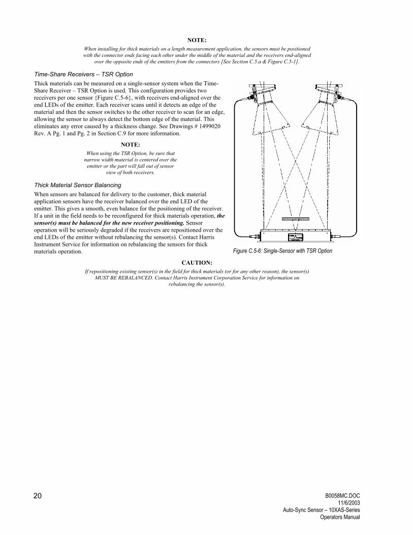
Time-Share Receivers � TSR Option Thick materials can be measured on a single-sensor system when the Time-Share Receiver � TSR Option is used. This configuration provides two receivers per one sensor {Figure C.5-6}, with receivers end-aligned over the end LEDs of the emitter. Each receiver scans until it detects an edge of the material and then the sensor switches to the other receiver to scan for an edge, allowing the sensor to always detect the bottom edge of the material. This eliminates any error caused by a thickness change. See Drawings # 1499020 Rev. A Pg. 1 and Pg. 2 in Section C.9 for more information.
NOTE: When using the TSR Option, be sure that
narrow width material is centered over the emitter or the part will fall out of sensor
view of both receivers.
Thick Material Sensor Balancing When sensors are balanced for delivery to the customer, thick material application sensors have the receiver balanced over the end LED of the emitter. This gives a smooth, even balance for the positioning of the receiver. If a unit in the field needs to be reconfigured for thick materials operation, the sensor(s) must be balanced for the new receiver positioning. Sensor operation will be seriously degraded if the receivers are repositioned over the end LEDs of the emitter without rebalancing the sensor(s). Contact Harris Instrument Service for information on rebalancing the sensors for thick materials operation.
CAUTION: If repositioning existing sensor(s) in the field for thick materials (or for any other reason), the sensor(s)
MUST BE REBALANCED. Contact Harris Instrument Corporation Service for information on rebalancing the sensor(s).
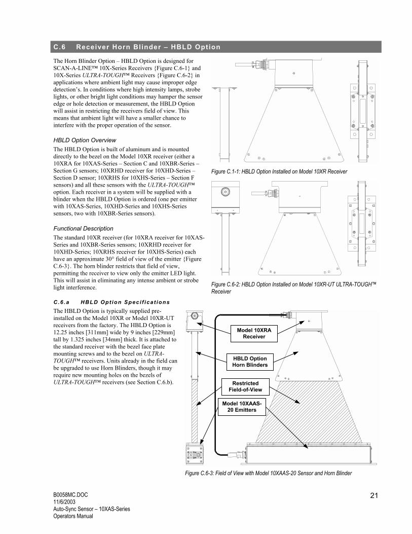
The Horn Blinder Option � HBLD Option is designed for SCAN-A-LINE� 10X-Series Receivers {Figure C.6-1} and 10X-Series ULTRA-TOUGH� Receivers {Figure C.6-2} in applications where ambient light may cause improper edge detection�s. In conditions where high intensity lamps, strobe lights, or other bright light conditions may hamper the sensor edge or hole detection or measurement, the HBLD Option will assist in restricting the receivers field of view. This means that ambient light will have a smaller chance to interfere with the proper operation of the sensor.
HBLD Option Overview The HBLD Option is built of aluminum and is mounted directly to the bezel on the Model 10XR receiver (either a 10XRA for 10XAS-Series � Section C and 10XBR-Series � Section G sensors; 10XRHD receiver for 10XHD-Series � Section D sensor; 10XRHS for 10XHS-Series � Section F sensors) and all these sensors with the ULTRA-TOUGH� option. Each receiver in a system will be supplied with a blinder when the HBLD Option is ordered (one per emitter with 10XAS-Series, 10XHD-Series and 10XHS-Series sensors, two with 10XBR-Series sensors).
Functional Description The standard 10XR receiver (for 10XRA receiver for 10XAS-Series and 10XBR-Series sensors; 10XRHD receiver for 10XHD-Series; 10XRHS receiver for 10XHS-Series) each have an approximate 30° field of view of the emitter {Figure C.6-3}. The horn blinder restricts that field of view, permitting the receiver to view only the emitter LED light. This will assist in eliminating any intense ambient or strobe light interference.
C.6 .a HBLD Opt ion Spec i f ica t ions The HBLD Option is typically supplied pre-installed on the Model 10XR or Model 10XR-UT receivers from the factory. The HBLD Option is 12.25 inches [311mm] wide by 9 inches [229mm] tall by 1.325 inches [34mm] thick. It is attached to the standard receiver with the bezel face plate mounting screws and to the bezel on ULTRA-TOUGH� receivers. Units already in the field can be upgraded to use Horn Blinders, though it may require new mounting holes on the bezels of ULTRA-TOUGH� receivers (see Section C.6.b).
Figure C.1-1: HBLD Option Installed on Model 10XR Receiver
Figure C.6-2: HBLD Option Installed on Model 10XR-UT ULTRA-TOUGH� Receiver
Figure C.6-3: Field of View with Model 10XAAS-20 Sensor and Horn Blinder
Model 10XRAReceiver
HBLD OptionHorn Blinders
Restricted Field-of-View
Model 10XAAS-20 Emitters
B0058MC.DOC 11/6/2003
Auto-Sync Sensor � 10XAS-Series Operators Manual
22
Separation Settings The SCAN-A-LINE� emitter and receiver can typically be mounted with a separation anywhere from one times the emitter length up to 72 inches [1829mm] (extended separations are available under an Engineering Variance Order only). Depending upon the emitter-to-receiver separation, the HBLD Option has mounting holes for the blinder end bars to restrict the field of view. The settings {Figure C.6-4} on the blinder are:
A) One times emitter length emitter-to-receiver separation {minimum separation} (i.e. Model 10X-10 with emitter-to- receiver separation of 15 inches [381mm]); B) Two times emitter length emitter-to-receiver separation {suggested separation}(i.e. 10X-10 with emitter-to-receiver separation of 20 inches [508mm]); C) Over two times emitter length emitter-to-receiver separation up to 72 inches [1829mm] {maximum separation} (i.e. 10X-10 with emitter-to-receiver separation of 70 inches [1778mm] {optional separation}).
Finishes The HBLD Option is typically supplied with all surfaces black anodized and the interior of the blinder painted in flat black (to reduce reflected glare). When supplied with an ULTRA-TOUGH� sensor (UT Option), the horn blinder may be painted with nitro blue polane paint at the customers request.
C.6 .b Ins ta l la t ion Usually, the HBLD Option is supplied with the sensor when it is ordered. Sometimes though the HBLD Option must be ordered after the sensor has been installed. The following sections detail the installation of the HBLD Option on both the standard Model 10XR receiver and the Model 10XR-UT ULTRA-TOUGH� receiver.
10XR-Series Receiver The installation of 10XR-Series receivers can be performed with the receiver on-line IF your company policies allow and/or IF the receiver is easily accessible. If either of these cases exist, remove the receiver from the line BEFORE performing the following procedure. Kit should contain the assembled horn blinder and four screws, flat washers and lock washers.
1) Remove any existing blinder from the receiver, if applicable.
2) Determine the separation of the emitter-to-receiver and set the end bars for that separation (Section C.6.a & Figure C.6-5) by loosening the �A� screws and removing the �B� screws. Rotate the end bars until �B� holes line up and insert the �A� screws. Tighten all screws securely.
3) Remove the four bezel retaining screws {Figure C.6-6}. Be sure to hold the bezel in place when the screws are removed.
4) Exchange the four bezel retaining screws with the new screws, lockwashers and flat washers supplied with the horn blinder.
5) Align the Horn Blinder with the outer holes over the bezel retaining holes {Figure C.6-7}.
6) Assembly the screws with a lock washer first and the flat washer second {Figure C.6-
8}.
7) Insert the four mounting screws into the bezel and finger tighten {Figure C.6-8}.
8) Visually inspect that the horn blinder is aligned properly {Figure C.6-9} and tighten the mounting screws securely (be careful not to over-tighten the screws, as they are stainless steel screws threading into cast aluminum).
If necessary, use the Model AA10X Alignment Adapter (Section AA) and an
oscilloscope to check the view of the emitter and the receiver output. Review the sensor manual section to verify proper operation of the sensor with the horn blinder attached.
10XR-Series ULTRA-TOUGH� Receiver The installation for 10XR-Series ULTRA-TOUGH� receivers can be performed with the receiver on-line IF your company policies allow and/or IF the receiver is easily accessible. If either of these cases exist, remove the receiver from the line BEFORE performing the following procedure. Kit should contain the assembled horn blinder and four screws, flat washers and lock washers.
1) Remove any existing blinder from the receiver, if applicable.
2) Determine the separation of the emitter-to-receiver and set the end bars for that separation (Section C.6.a & Figure C.6-5) by loosening the �A� screws and removing the �B� screws. Rotate the end bars until �B� holes line up and insert the �A� screws. Tighten all screws securely.
3) Align the Horn Blinder with the inner holes over the bezel retaining holes {Figure C.6-10}.
4) Assemble the screws with a lock washer first and the flat washer second {Figure HH.3-4 next page}.
5) Insert the four mounting screws into the bezel and finger tighten {Figure C.6-11}.
6) Visually inspect that the horn blinder is aligned properly {Figure C.6-12} and tighten the mounting screws securely (be careful not to over-tighten the screws, as they are stainless steel screws threading into aluminum).
If necessary, use the Model AA10X Alignment Adapter (Section AA) and an oscilloscope to check the view of the emitter and the receiver output. Review the sensor manual section to verify proper operation of the sensor with the horn blinder attached.
NOTE:
Figure C.6-6: Model 10XR Bezel Retaining Screws
Figure C.6-7: Blinder Mounting Holes
Figure C.6-9: Horn Blinder Properly Aligned on Model 10XR Receiver
Figure C.6-8: Horn Blinder Screw Assembly on Model 10XR Receiver
Figure C.6-10: Model 10XR-UT Blinder Mounting Holes
Figure C.6-11: Horn Blinder Screw Assembly on Model 10XR-UT ULTRA-TOUGH� Receiver
Bezel Retaining Screws
Mounting Holes
Mounting Holes
MountingHoles
B0058MC.DOC 11/6/2003
Auto-Sync Sensor � 10XAS-Series Operators Manual
24
Older Model 10XR-UT receiver bezels may not have the mounting holes drilled and tapped on the bezel for the Horn Blinder mounting screws. These bezels must be machined to accept the
Horn Blinder.
C.6 .c T rouble Shoot ing Trouble shooting the HBLD Option is relatively simple. First, verify that all screws of the unit are secure. The alignment of the receiver to the emitter is fairly critical because of the restricted field-of-view. Review the sensor section of this manual for information on the alignment of the receiver and the emitter.
Figure C.6-12: Horn Blinder Properly Aligned on Model 10XR-UT ULTRA-TOUGH� Receiver
All SCAN-A-LINE� sensors are highly reliable and tolerant to most industrial environments. Maintenance of the 10XAS-Series after installation is extremely limited. Since there are no moving parts in the 10XAS-Series, there is nothing to lubricate. If any form of maintenance is performed on the line near the 10XAS-Series sensor, be sure to cover the sensors view windows to protect the viewing window from hot or falling objects.
Internal maintenance and repair of SCAN-A-LINE� sensors is NOT RECOMMENDED by Harris Instrument Corporation and MAY VOID THE WARRANTY. Please contact Harris Instrument Corporation Service for information on board and component maintenance of 10XAS-Series sensors.
WARNING: If welding is to be performed anywhere on the process line where the 10XAS-Series is installed,
disconnect ALL cables from the 10XAS-Series. This prevents system overload from the current generated by the welding equipment.
The only typical maintenance for the 10XAS-Series sensor is:
1) Check all cable connections. All connections should be snug. 2) Check all cables for cuts, crimps or other damage that could cause short circuits. 3) Clean the viewing window. Even though the 10XAS-Series can operate with an almost 90% attenuation of the light source,
cleaning the window will insure constant and reliable edge detection�s. 4) Check all mounting fixtures. Tighten if necessary. In high vibration environments, mounting plates can vibrate loose, which
may change the emitter-to-receiver alignment. If vibration is still causing problems, simple vibration dampening can solve most cases of vibration interference.
C.7 .a Lexan ® Beze l Replacement The Lexan® bezel on Model 10XAAS emitters are designed to be field replaceable. If the Lexan® bezel has been damaged (scratched or pitted), contact Harris Instrument Corporation Service for a replacement bezel and instructions for replacing the bezel.
C.7 .b Cab le Bui ld ing & Repa i r In many applications, the cables that are supplied with SCAN-A-LINE� sensor systems need to be modified for installation; or repaired because of incidental damage. Harris Instrument Corporation can supply custom cables for special situations and we suggest that you order the cables directly from Harris Instrument Corporation. Installation of customer-built cables that are improperly wired is one of the major causes of malfunction of SCAN-A-LINE� systems (next to strip collisions). Improperly built cables can CAUSE SERIOUS DAMAGE to the SCAN-A-LINE� system and the installation of customer-supplied cables MAY VOID THE WARRANTY of the SCAN-A-LINE� equipment. For further information on customer-supplied and/or built cables, please contact Harris Instrument Corporation Sales or Service.
In many cases, the customers electrical maintenance personnel will be modifying the cables for routing through conduit or direct wiring of power. Please review the processing unit Section [Sections P through Z] for more information on direct wiring of system power. The current section describes the proper procedures for building and/or repairing cables. Be aware that this section only covers the standard cables supplied with all SCAN-A-LINE� sensors and processors. It does not necessarily pertain to cables supplied with Engineering Variance Orders (EVO�s). Contact Harris Instrument Corporation Engineering for further information on cabling instructions for EVO installations.
B0058MC.DOC 11/6/2003
Auto-Sync Sensor � 10XAS-Series Operators Manual
26
General Cable-Building Procedures Please review this section BEFORE attempting to build a custom cable. These specifications, if followed fully and correctly, will help ensure that the cable is built to operate properly with 10XAS-Series sensors.
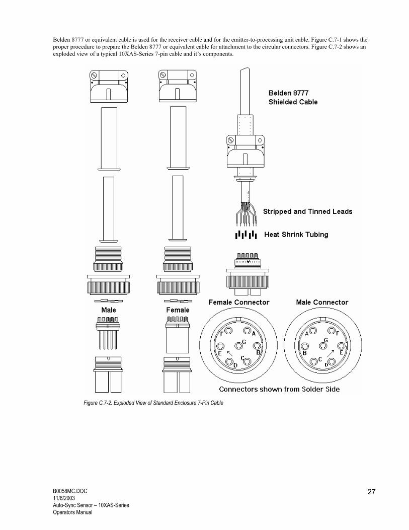
Belden 8777 or equivalent cable is used for the receiver cable and for the emitter-to-processing unit cable. Figure C.7-1 shows the proper procedure to prepare the Belden 8777 or equivalent cable for attachment to the circular connectors. Figure C.7-2 shows an exploded view of a typical 10XAS-Series 7-pin cable and it�s components.
Figure C.7-2: Exploded View of Standard Enclosure 7-Pin Cable
B0058MC.DOC 11/6/2003
Auto-Sync Sensor � 10XAS-Series Operators Manual
28
NOTE: ULTRA-TOUGH� enclosures utilize watertight versions of the 6- and 7-pin cables listed below. Contact
Harris Instrument Corporation for information on building watertight cables if necessary.
Receiver Cable The MS-style circular connectors on the standard receiver cable are of two different types. On the end that attaches to the receiver, the shell is a 97-3101A-14S inline connector with 97-3057-6 strain relief, 97-79-513-6 rubber boot and a 97-14S-6S female insert. The standard connector that attaches to the 6-pin bulkhead on the emitter is a 97-3106A-14S shell, 97-3059-6 strain relief, 97-79-513-6 rubber boot and a 97-14S-06P male plug insert. Drawing number 3495104 Rev A shows the pinouts of the circular Inline connectors for both ends of the receiver cable.
The ULTRA-TOUGH� (UT Option) option require a sealed circular connector MS3106E14S-6P on the end of the cable that attaches to the emitter 6-pin circular bulkhead. Drawing number 3495109 Rev A shows the pinouts of the sealed receiver cable.
Emitter-to-Processing Unit Cable The standard enclosure emitter-to-processing unit cable also has two circular connectors. On the end that attaches to the emitter is a 97-3106A-16S shell, 97-3057-8 strain relief, 97-79-513-8 rubber boot and a 97-16S-1S female insert. The end that attaches to the processing unit is a 97-3106A-16S shell, 97-3057-8 strain relief, 97-79-513-8 rubber boot and a 97-16S-1P male plug insert. Drawing number 3486060 Rev A shows the pinouts of the circular connectors for both ends of the emitter-to-processing unit cable. The ULTRA-TOUGH� (UT Option) option requires a sealed circular connector MS3106E16S-1S on the end of the cable that attaches to the emitter 7-pin circular bulkhead. The inline connector is the same as the standard enclosure emitter-to-processor cable. Drawing number 3495109 Rev A shows the pinouts of the sealed emitter-to-processing unit cable.
Typical Cable Building Tutorial Review Figure C.7-1 and C.7-2 for information on building a typical SCAN-A-LINE� cable. The following tutorial will assist, in association with these pictures, in assuring that the cable is properly built.
1) Determine the length of the cable to be cut. Use only Belden 8777 cable or equivalent. Cut the cable to the proper length. 2) Starting on one end, cut the outer (gray) insulation, being sure not to cut the internal wire insulation, approximately two
inches [51mm] from the end of the cable. Remove the cut insulation. Pull back the gray outer insulation approximately four inches [102mm].
3) Peel back the foil on the internal wire pairs and remove down to the insulation cut point. 4) Separate the shields. Separate out the three pairs of wires (green & black, white & black, red & black) and twist each pair
together (twist the green & black together, etc.). 5) Cut a four inch [102mm] 24-guage wire in gray. Cut shields to approximately one inch [25mm] in length. Strip the ends of
the four inch [102mm] gray wire approximately one inch [25mm]. Connect shields and the gray wire with a Western Union splice, solder and shrink wrap.
6) Tuck shrink wrapped shields back into cable bundle and push gray outer insulation back up to cover the shields. 7) Strip and tin all wire ends approximately one-half inch [13mm]. 8) Check the wiring diagram for the cable being built (i.e., if receiver extension cable, check drawing #3495104 Rev A) for the
wire connections, circular connector pinouts, circular connector shell type and circular connector insert type. Run the cable through the appropriate rubber boot, strain relief, and circular connector shell.
9) Verify the pinout locations on the back of the circular connector insert with the proper drawing. Run the wires through a small piece of heat shrink tubing (approximately 0.375 inch [10mm]) and solder the correct wires to their corresponding circular connector pinouts. Heat the heat shrink tubing.
10) Attach the circular connector insert to the circular connector shell with the split retaining ring. Assemble the circular connector and tighten all connections securely.
C.7 .c Reposi t ion ing Sensors If at any time the sensor(s) is repositioned, or the receiver position over the emitter is changed, the sensor(s) MUST BE REBALANCED for the new position or configuration. Even instances where the product passline is altered, the sensor may need rebalanced (for edge guide or measurement applications). Contact Harris Instrument Corporation Service for more information on rebalancing the sensor(s).
The following procedures are designed to isolate problems that may occur in systems that are installed and have been operating properly. For installation problems, see the installation portion of this manual, or contact your SCAN-A-LINE� representative or Harris Instrument Corporation for more information.
1) Begin with a thorough visual inspection of the system under test. Before testing for circuit malfunctions, ensure the power switch is on and that power is supplied to the system.
2) Verify that the emitter and receiver lenses are unbroken, reasonably clean and free of foreign material. Cracked lenses, excessive dirt and foreign material on the lens can cause the system to perform incorrect edge detection�s.
3) Examine all cables for cuts, nicks or crimps that could cause open or short circuits. Ensure that all connectors are secure and free of foreign material. If in doubt, replace the cable(s) with known, good spare cables.
For this next trouble shooting procedure, refer to the processing unit�s Operators Manual section for the locations of the �VIDEO A�, �VIDEO B� and �COMMON� positions on the processing unit�s main board.
4) Measure the voltage from the �VIDEO A� (and �VIDEO B� if a dual-sensor system) to �COMMON� on the processing unit�s emitter cable connection {Figure C.8-1 for Model HDPU Level 1, Model PCPU, Model TCPU; Figure C.8-2 for Model DCPU and Model MPPU; for Model GPU, Model HDPU Level 2, refer to their respective manual sections}. With a digital voltmeter, these should read 12VDC (11.6VDC to 12.4VDC) with the emitters uncovered and 0VDC (0VDC to 0.4VDC) with the emitters covered. If these voltages are incorrect, check all cables and cable connections again to verify there are no loose or shorted cables. Then replace the entire incorrect sensor with a know good spare and recheck the voltages. If the voltages read correctly with the spare, the original sensor was malfunctioning. If the voltages still read incorrect with the know good spare, the cable is possibly malfunctioning. Contact Harris Instrument Corporation Service immediately for more information.
Further trouble shooting of the sensors is only possible with the sensor connected to the processing unit. All diagnostics for the sensor rely upon the diagnostic circuitry in the processing unit. See the processing unit�s Operators Manual for more information.
Figure C.8-1: Model HDPU Level 1, Model PCPU & Model TCPU VIDEO & COMMON Test Points
Figure C.8-2: Model DCPU & Model MPPU VIDEO & COMMON Test Points
B0058MC.DOC 11/6/2003
Auto-Sync Sensor � 10XAS-Series Operators Manual
30
C.9 Related Drawings
The following pages contain various drawings for the components used in and with the 10XAS-Series. All mechanical drawings are available as AutoCAD® .DWG files for a minimal charge. Please contact Harris Instrument Corporation Sales for more information.