Java 3D is a high level, scene graph based Application Programming Interface (API). It can use either DirectX or OpenGL to take advantage of 3D hardware acceleration. The best source of information regarding Java 3D is the Sun Microsystems Java 3D API pages.
Installation
To run and install the Java 3D, Java 2 (JDK 1.3.1 minimum) and the Java 3D API 1.3 are required (other information and system requirements are discussed elsewhere). The Java 3D API and associated documentation are available as follows:
• Java 3D API 1.3 Implementation (java3d-1_3_1-windows-i586-opengl-sdk.exe) *This is the implementation that will be used for this course.
• Java 3D API 1.3 Specification (java3d-1_3-fr-guide.zip = 2,281,562 bytes) • Java 3D API 1.3 Implementation (java3d-1_3-windows-i586-directx-sdk.exe =
6,760,406 bytes) • Java 3D 1.3 Implementation Documentation (java3d-1_3_1-doc.zip) • Java 3D 1.3 API Documentation (does not include documentation for com.sun.j3d
utilities j3dapi.zip = 1,191 kB)
• Java 3D API Tutorial (j3d_tutorial.zip = 3,003 kB) • Java 3D API Examples (examples1_6.jar = 318 kB) • Java 3D Class Hierarchy Diagram Sun
Once the Java 3D has been obtained 'Click' the java3d-1_3-i586-opengl-sdk.exe and the 'installanywhere.exe' will upgrade your current Java 2 installation with the Java 3D optional package. The installer locates your current JVM (Java Virtual Machine) to upgrade with Java 3D (default location is C:/j2sdk1.4.0/jre (for JRE) and C:/j2sdk1.4.0 (for JDK)).
Exercise 3D1: Installation
Install the following:
• Java 3D API 1.3 Implementation (java3d-1_3-windows-i586-opengl-sdk.exe = 6,667,270 bytes)
• Java 3D API 1.3 Specification (java3d-1_3-fr-guide.zip = 2,281,562 bytes) • Java 3D 1.3 Implementation Documentation (java3d-1_3-doc.zip = 1,843,021 bytes)
Documentation: G:/j2sdk1.4.2/html
Getting Started
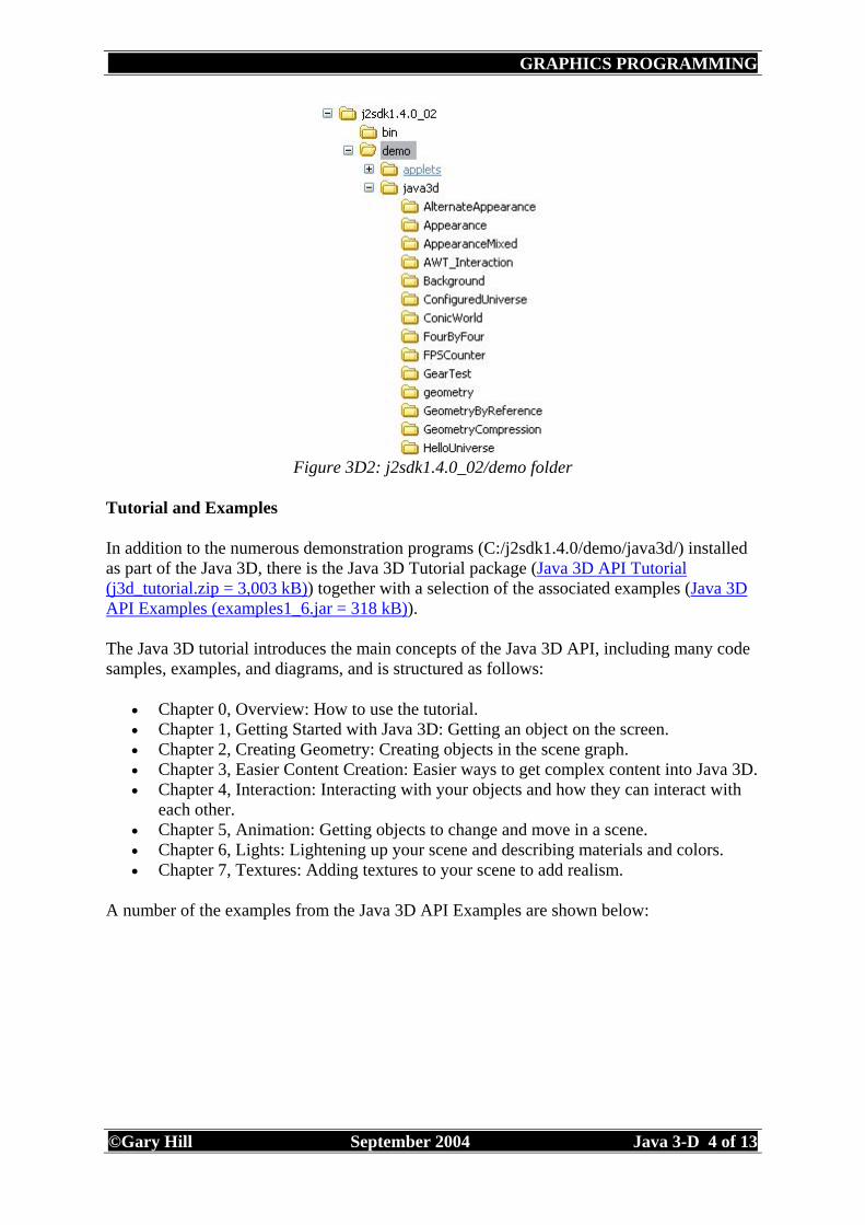
The Java 3D API implementation installs a number of demonstration programs (C:/jdk1.4.0/demo/java3d/). It is useful to run one of these to check the installation has worked correctly. The recommended program in the README file (C:/j2sdk1.4.0/README.java3d.win32ogl) is HelloUniverse.java (C:/j2sdk1.4.0/demo/java3d/). All demonstration programs can be run from your browser using index.html or by selecting thm from within the SunOne IDE (Integrated Development Environment).
Figure 3D1: HelloUniverse.java
Exercise 3D2: Demonstartion Examples
Run a selection of the demo programs using the SunOne IDE. In particular compile and run HelloUniverse.java and then look at the code
In addition to the numerous demonstration programs (C:/j2sdk1.4.0/demo/java3d/) installed as part of the Java 3D, there is the Java 3D Tutorial package (Java 3D API Tutorial (j3d_tutorial.zip = 3,003 kB)) together with a selection of the associated examples (Java 3D API Examples (examples1_6.jar = 318 kB)). The Java 3D tutorial introduces the main concepts of the Java 3D API, including many code samples, examples, and diagrams, and is structured as follows:
• Chapter 0, Overview: How to use the tutorial. • Chapter 1, Getting Started with Java 3D: Getting an object on the screen. • Chapter 2, Creating Geometry: Creating objects in the scene graph. • Chapter 3, Easier Content Creation: Easier ways to get complex content into Java 3D. • Chapter 4, Interaction: Interacting with your objects and how they can interact with
each other. • Chapter 5, Animation: Getting objects to change and move in a scene. • Chapter 6, Lights: Lightening up your scene and describing materials and colors. • Chapter 7, Textures: Adding textures to your scene to add realism.
A number of the examples from the Java 3D API Examples are shown below:
As with the demo programs, run a selection of the tutorial programs using the SunOne IDE. Compile and run a selection and then look at the code.
Introduction to Java 3D Resourses:
Selman (2002) Chapter 1: What is Java 3D and is it for me? Walsh, Gehringer (2002) Java 3D API Jump Start, Prentice Hall, Chapter 1: Java 3D Overview Slater, Steed, Chrysanthou () Computer Graphics and Virtual Environments From Realism to Real-Time, Pearson, Chapter 1: Introduction.
It was mentioned in the introduction that Java 3D is a high level, scene graph based Application Programming Interface (API) (together with VRML, XML, Inventor, Performer, Optimizer) that uses OpenGL or DirectX for rendering. Before writing a Java 3D aplication it is useful to define the term 'scene graph'.
Scene Graph Defined
'There are a number of hallmarks of scene graph software. First is the concept that the scene graph data structures are designed to be optimal for rendering, as opposed to optimal for searching or editing once created. Second is that the scene graph software provides some additional value above and beyond the graphics platform itself. The graphics platform is a rendering engine or platform, such as OpenGL [and Direct3D, Glide]. The interface to graphics platforms is often simplistic and detail oriented, reflecting design goals that emphasize maximum rendering performance. Programming interfaces to graphics platforms are often verbose in terms of the number of lines of code needed to draw a pixel. Scene graph software is often characterized as a set of tools that extend the base functionality of a graphics platform in a number of ways, most often by providing complex services that are encapsulated behind a simpler and more compact interface. Additionally, there may be fundamental primitive types present in the scene graph model that are not present in the graphics platform, such as procedural surfaces or volumetric objects. A powerful use of scene graph models stems from the ability to create a pseudo-framework for performing view-dependent operations, such as changing the object database as a function of viewpoint. From a design perspective, scene graph models are often thought of as trees. Leaf nodes in the tree contain renderable data, such as triangles or line segments. Interior nodes contain render state information, such as object color, light sources, cameras and so forth.
Figure 3D6: 3D Theory Scene Graph: Tree (Martin Baker)
The fundamental usage model for scene graph systems is that applications first create a "scene graph" using tools provided by the system, populate the tree with data, then ask the system to render the tree. Such a model is intuitive and easy to use. Applications developers benefit from this model because they have a single interface to regardless of the underlying platform or of the specific application domain'. (Bethel (1999) RM Scene Graph Technical White Paper). A scene graph is a hierarchical approach to describing objects and their relationship to each other. For example, you would describe the connection of your hand relative to your arm. That way, when moving your arm, the hand moves with it. However, you can describe the angle of rotation of the hand in an angle that is relative to the arm. This description of information relative to the parent object is termed a local coordinate system, and is the heart of the scene graph approach to 3D graphics.
As you descend each level, there is a grouping structure. Typically this grouping structure contains objects of similar characteristics and always has something useful from the parent. Our hand/arm example is typical. Usually at each group there is the ability to move the object relative to the parent. (Couch (1999) Raw J3D).
Java 3D Scene Graph
The figure below illustrates the scene graph model for Java 3D. The object hierarchy shows that all Java 3D scene graphs start with a VirtualUniverse as the root node, which in turn connects to a Locale object. The scene graph below the Locale splits into two 'branch graphs' i.e. BranchGraph. The left hand BranchGraph contains a BranchGroup for the content (sometimes called the content branch) and the right hand BranchGraph contains a BranchGroup for the view (sometimes called the view branch).
The coordinate system for Java 2D places the origin for x and y at the top left hand corner of the screen. However, the default origin position in Java 3D for x, y and z is at the center of the screen. To confuse matters the y axis is now positive upwards from the screen and positive z is out of the screen toward the viewer (right hand rule). Additionally, any units specified are all in metres.
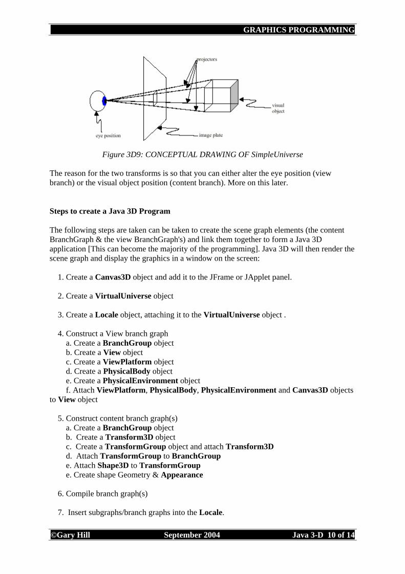
NB: Vertices: A vertex is a 3 dimensional, x, y, z, co-ordinate of a point. Therefore vertices are a collection of points. Both the view branch and the content branch within a scene graph contain transforms (TransformGroup's). The view looks at the visual object through the image plate (as below).
The reason for the two transforms is so that you can either alter the eye position (view branch) or the visual object position (content branch). More on this later.
Steps to create a Java 3D Program
The following steps are taken can be taken to create the scene graph elements (the content BranchGraph & the view BranchGraph's) and link them together to form a Java 3D application [This can become the majority of the programming]. Java 3D will then render the scene graph and display the graphics in a window on the screen: 1. Create a Canvas3D object and add it to the JFrame or JApplet panel. 2. Create a VirtualUniverse object 3. Create a Locale object, attaching it to the VirtualUniverse object . 4. Construct a View branch graph a. Create a BranchGroup object b. Create a View object c. Create a ViewPlatform object d. Create a PhysicalBody object e. Create a PhysicalEnvironment object f. Attach ViewPlatform, PhysicalBody, PhysicalEnvironment and Canvas3D objects to View object 5. Construct content branch graph(s) a. Create a BranchGroup object b. Create a Transform3D object c. Create a TransformGroup object and attach Transform3D d. Attach TransformGroup to BranchGroup e. Attach Shape3D to TransformGroup e. Create shape Geometry & Appearance 6. Compile branch graph(s) 7. Insert subgraphs/branch graphs into the Locale.
The steps 1,2,3,4,and 7 create a Simple Universe( code for creating a SimpleUniverse: SimpleUniverse ( ) )
Figure 3D10: Object Hierarchy (sun)
Figure 3D11: Application Scene Graph Model (sun)
Code for the Scene Graph
The Java 3D code within a constructor class would look like below: VirtualUniverse yourUniverse = new VirtualUniverse(); //create VU Locale yourLocale = new Locale(yourUniverse); //create Locale yourLocale.addBranchGraph(constructViewBranchGroup(myCanvas3D)); //add view branch yourLocale.addBranchGraph(constructContentBranchGroup(myShape()));//add content branch The VirtualUniverse is often referred to as the three dimensional virtual space that the Java 3D objects populate.
The Locale establishes the Cartesian coordinate system within the VirtualUniverse. Here we will be considering one Locale, which equates to one coordinate system for the VirtualUniverse.
View Branch
The View Branch (BranchGroup) will specify the viewing parameters, such as viewing location and direction.
Note: BranchGroup - 'The BranchGroup serves as a pointer to the root of a scene graph branch; BranchGroup objects are the only objects that can be inserted into a Locale's set of objects'. TransformGroup - 'Group node that contains a transform. The TransformGroup node specifies a single spatial transformation, via a Transform3D object, that can position, orient, and scale all of its children'. ViewPlatform - 'The ViewPlatform leaf node object controls the position, orientation and scale of the viewer. It is the node in the scene graph that a View object connects to. A viewer navigates through the virtual universe by changing the transform in the scene graph hierarchy above the ViewPlatform'. View - 'A view contains a list of Canvas3D objects that the view is rendered into. It exists outside of the scene graph, but attaches to a ViewPlatform leaf node object in the scene graph. It also contains a reference to a PhysicalBody and a PhysicalEnvironment object' (Sun - Java 3D 1.3 Implementation Documentation).
The Content Branch (BranchGroup) will specify the geometry, appearance, behaviour, location, sound and lights, which comprise the content of the Virtual Universe.
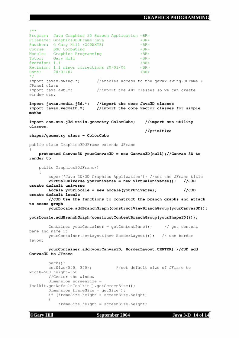
The example below shows a ColorCube (com.sun.j3d.utils.geometry package, which includes primitive shapes/geometry classes of standard shapes) rotated 30 degrees about the x and y axes (Content Branch) and viewed back 10 units (metres) along the z axis (View Branch). This example is shown to illustrate a simple Java 3D program following the steps listed above. Various sections of the program will be considered in more detail later in the notes.
public static void main(String[] args) { Graphics3DJFrame test = new Graphics3DJFrame();//instantiate Graphics3DJFrame object test.setDefaultCloseOperation(JFrame.EXIT_ON_CLOSE); //close frame Swing way } }
Exercise 3D4: Graphics3DJFrame
Within the SunOne IDE, compile and run the Graphics3DJFrame.java application above. Carefully read through the code and add verbose comments to assist your understanding. Then alter some of the parameters such as the ColorCube scaling factor, the Transform3D 'viewObjectFrom' view position and the Transform3D 'rotateShape' x, y, z and rotation for the content. Attempt to discover what each does and its affect on the content and view.
Scene Graph Resourses:
Barrilleaux (2001) 3D User Interfaces with Java 3D, Chapter 11: UI spaces and the scene graph
The ColorCube class may be one of the easiest classes to use when demonstrating Java 3D, but it is very limited in its use (it extends Shape3D). The shape (Geometry) and colour (Appearance) are fixed. From the Scene Graph figures above (Figure 3D11) it can be seen that each Shape3D can have a Geometry and Appearance node, or just a Geometry node. To investigate Shapes here a default Appearance wil be used.
Within the Sun utility classes (com.sun.j3d.utils.geometry) are classes for creating Box, Cone, Cylinder and Sphere as geometric primitives (they extend Pimitive).
Box
By default, the Box has length, width and height of 2 metres, with the origin at its centre [0, 0, 0] and the corresponding corners at [1, 1, 1] and [-1, -1, -1]. The constructor details are as follows:
• Box() - Constructs a default box • Box(float x, float y, float z, Appearance ap) - Constructs a box of a given
dimension and appearance. • Box(float x, float y, float z, int primflags, Appearance ap, int numTextUnit) -
Constructs a box of a given dimension, flags and appearance. • Box(float x, float y, float z, int primflags, Appearance ap) - Constructs a box of a
The Cone is defined with a radius and height. It is a capped cone centered at the origin with its central axis aligned along the Y-axis. The center of the cone is defined to be the center of its bounding box (rather than its centroid). The constructor details are as follows:
• Cone() - Constructs a default Cone of radius of 1.0 and height of 2.0. Resolution defaults to 15 divisions along X and axis and 1 along the Y axis.
• Cone(float radius, float height) - Constructs a default Cone of a given radius and height.
• Cone(float radius, float height, Appearance ap) - Constructs a default cone with appearance.
• Cone(float radius, float height, int primflags, Appearance ap) - Constructs a default with primitive flags and appearance.
• Cone(float radius, float height, int primflags, int xdivision, int ydivision, Appearance ap) - Constructs a customized Cone of given flags, resolution (X and Y dimensions), and appearance.
The Cylinder is defined with a radius and height. It is a capped cylinder centered at the origin with its central axis aligned along the Y-axis. The constructor details are as follows:
• Cylinder() - Constructs a default cylinder of radius of 1.0 and height of 2.0. Resolution defaults to 15 divisions along X axis and 1 along the Y axis.
• Cylinder(float radius, float height) - Constructs a default cylinder of a given radius and height.
• Cylinder(float radius, float height, Appearance ap) - Constructs a default cylinder of a given radius, height, and appearance.
• Cylinder(float radius, float height, int primflags, Appearance ap) - Constructs a default cylinder of a given radius, height, primitive flags and appearance.
• Cylinder(float radius, float height, int primflags, int xdivision, int ydivision, Appearance ap) - Constructs a customized cylinder of a given radius, height, resolution (X and Y dimensions), and appearance.
The Sphere is created with a given radius and resolution. It is centered at the origin. The constructor details are as follows:
• Sphere(float radius) - Constructs a Sphere of a given radius. The resolution defaults to 15 divisions along sphere's axes. Appearance defaults to white.
• Sphere() - Constructs a default Sphere of radius of 1.0. Resolution defaults to 15 divisions. Appearance defaults to white.
• Sphere(float radius, Appearance ap) - Constructs a Sphere of a given radius and appearance.
• Sphere(float radius, int primflags, Appearance ap) - Constructs a Sphere of a given radius and appearance with additional parameters specified by the Primitive flags.
• Sphere(float radius, int primflags, int divisions) - Constructs a Sphere of a given radius and number of divisions with additional parameters specified by the Primitive flags. Appearance defaults to white.
• Sphere(float radius, int primflags, int divisions, Appearance ap) - Constructs a customized Sphere of a given radius, number of divisions, and appearance, with additional parameters specified by the Primitive flags. The resolution is defined in terms of number of subdivisions along the sphere's axes.
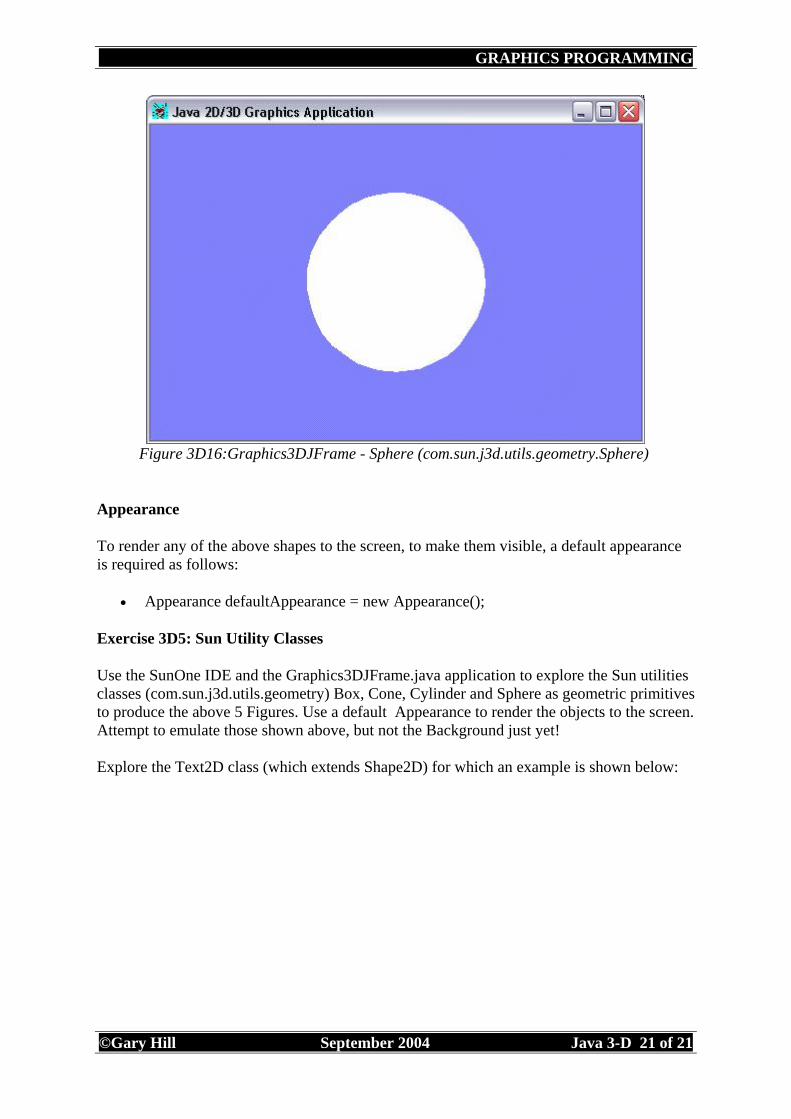
To render any of the above shapes to the screen, to make them visible, a default appearance is required as follows:
• Appearance defaultAppearance = new Appearance();
Exercise 3D5: Sun Utility Classes
Use the SunOne IDE and the Graphics3DJFrame.java application to explore the Sun utilities classes (com.sun.j3d.utils.geometry) Box, Cone, Cylinder and Sphere as geometric primitives to produce the above 5 Figures. Use a default Appearance to render the objects to the screen. Attempt to emulate those shown above, but not the Background just yet! Explore the Text2D class (which extends Shape2D) for which an example is shown below:
This section will consider the creation of geometric shapes using the GeometryArray class (javax.media.j3d.GeometryArray) and its subclasses GeometryStripArray, IndexedGeometryArray, LineArray, PointArray, QuadArray, TriangleArray.
Figure 3D18:GeometryArray (javax.media.j3d.GeometryArray) Sun
PointArray, LineArray, TriangleArray and QuadArray all possess the same basic constructor as follows:
• PointArray(int vertexCount, int vertexFormat) • LineArray(int vertexCount, int vertexFormat) • TriangleArray(int vertexCount, int vertexFormat) • QuadArray(int vertexCount, int vertexFormat)
Figure 3D19:GeometryArray Subclasses (javax.media.j3d.GeometryArray) Sun
The first subclass to consider in detail is QuadArray:
QuadArray
The constructor details are as follows:
• public QuadArray(int vertexCount, int vertexFormat) • public QuadArray(int vertexCount, int vertexFormat, int texCoordSetCount, int[]
texCoordSetMap)
To demonstrate the use of QuadArray, yet another cube will be created as below:
Then a QuadArray object is created with the vertex count as an integer (24) and the vertex format (QuadArray.COORDINATES, to indicate that vertice coordinates will be given). The code will be as follows: QuadArray shapeData = new QuadArray(24, QuadArray.COORDINATES); shapeData.setCoordinates(0, shapeCoordinates); The setCoordinates method has two parameters. The first is the index, which is the starting destination vertex index in the geometry array and the second refers to the coordinates, which is the source for the array of points containing the new coordinates.
Exercise 3D6: TriangleArray
Attempt to create a Triangular pyramid using TriangleArray. TriangleArray has a similar contructor to QuadArray (TriangleArray(int vertexCount, int vertexFormat)). The base vertices should be (-1.0f, -1.0f, 1.0f), (1.0f, -1.0f, 1.0f), (1.0f, -1.0f, -1.0f), (-1.0f, -1.0f, -1.0f) and the point (0.0f, 1.0f, 0.0f).
Hint: The base rectangle will need to be created from two triangles. This will give the equivalent of 6 faces.
Note: This will appear as a solid white shape (see Appearance later)
IndexedGeometryArray
IndexedGeometryArray includes the useful subclasses of IndexedGeometryStripArray, IndexedLineArray, IndexedPointArray, IndexedQuadArray, IndexedTriangleArray (see below).
Having already concentrated on the cube, the use of IndexedQuadArray and IndexedTriangleArray will be used to demonstrate two of the IndexedGeometryArray subclasses.
IndexedQuadArray
The constructors for IndexedQuadArray take the the same form as QuadArray as follows:
• IndexedQuadArray(int vertexCount, int vertexFormat, int indexCount) • IndexedQuadArray(int vertexCount, int vertexFormat, int texCoordSetCount, int[]
texCoordSetMap, int indexCount)
The main difference is the addition of the indexCount for the number of coodinates. For a cube the vertexCount will be 8 for each of the corner points/vertices and then the index count will be 24 for the number of points required to contruct the shape. See code below:
The second of the three parameters in the IndexedQuadArray, vertexFormat will always include COORDINATES, but could include a number of others that can be OR'd ('|') together:
• NORMALS, to signal the inclusion of per vertex normals • COLOR_3 or COLOR_4 - colour per vertex • TEXTURE_COORDINATE_2 or TEXTURE_COORDINATE_3 or
TEXTURE_COORDINATE_4 - texture coordinates 2D, 3D or 4D per vertex.
IndexedQuadArray.COORDINATES and IndexedQuadArray.NORMALS are included above. Although the normals are not specified in this case (A normal is a vertex which faces away from a face at right angles. This will be covered later).
IndexedTriangleArray
The constructors for IndexedTriangleArray take the the same form as IndexedQuadArray:
• IndexedTriangleArray(int vertexCount, int vertexFormat, int indexCount) • IndexedTriangleArray(int vertexCount, int vertexFormat, int texCoordSetCount,
int[] texCoordSetMap, int indexCount)
For a cube, made from triangles, the vertexCount will still be 8, but the number of triangles and hence the index count will need to be 36 vertices.
Exercise 3D7: IndexedTriangleArray
Attempt to create a cube made from triangles as below.
Note: The cube will be not appear as shown below, but as a solid white shape as in previous examples. The wire frame type appearance will be discussed later.
Figure 3D23:IndexedTriangleArray
Exercise 3D8: IndexedGeometryArray
Within the IndexedGeometryArray class only the subclasses of IndexedQuadArray and IndexedTriangleArray have been introduced. Using the Java 3D Specification attempt examples illustrating the use of the remaining subclasses: IndexedGeometryStripArray, IndexedLineArray and IndexedPointArray.
The earlier Scene Graphs have clearly shown the two BranchGraphs. The left hand BranchGraph, as previously discussed, contains a BranchGroup for the content (sometimes called the content branch). The content branch includes a Shape3D Node that requires information about the shape (Geometry) and colour (Appearance) of the content. From the partial Scene Graph figure below (Figure 3D24) it can be seen that each Shape3D will have a Geometry and Appearance Node. In the previous section we have dealt with the Geometry Node. Here we will discuss the Appearance.
Figure 3D24:Shape3D/Node Geometry and Appearance.
The Appearance object can define a number of rendering effects for our content, as follows:
The above list is extensive, therefore polygon attributes will be used to illustrate one of the Appearance attributes. The wire frame effect from the previous section will be created.
PolygonAttributes
The simplest way to instantiate PolygonAttributes is to create an object using the default constructor:
• PolygonAttributes()
Then use the setPolygonMode and setPolygonAttributes methods. The PolygonAttributes define how a polygon is drawn, this relates to the rasterization mode, for which there are three options:
• POLYGON_FILL - renders/draws by filling the interior between the vertices. The default mode.
• POLYGON_POINT - renders/draws as points at the vertices. • POLYGON_LINE - renders/draws as lines drawn between consecutive vertices.
To create a wire frame type appearance the POLYGON_LINE would be used. An instance of Appearance and PolygonAttributes are first created, then the setPolygonMode method used to set the PolygonAttributes to POLYGON_LINE and finally, the setPolygonAttributes method used to set the Appearance. The code to create this wire frame type appearance is as follows:
Figure 3D25:PolygonAttributes and ColoringAttributes
ColoringAttributes
The default line colouring used would be white. To change the line colouring, an instance of ColoringAttributes would need to be created, followed by a setColor method (for the ColoringAttributes instance) and finally the setColoringAttributes method used to set the Appearance again.
Use com.sun.j3d.utils.geometry primitive examples of Box, Cone, Cylinder and Sphere previously created. Alter them to use POLYGON_LINE. It is interesting to see how these geometric primitives are constructed.
PolygonAttributes
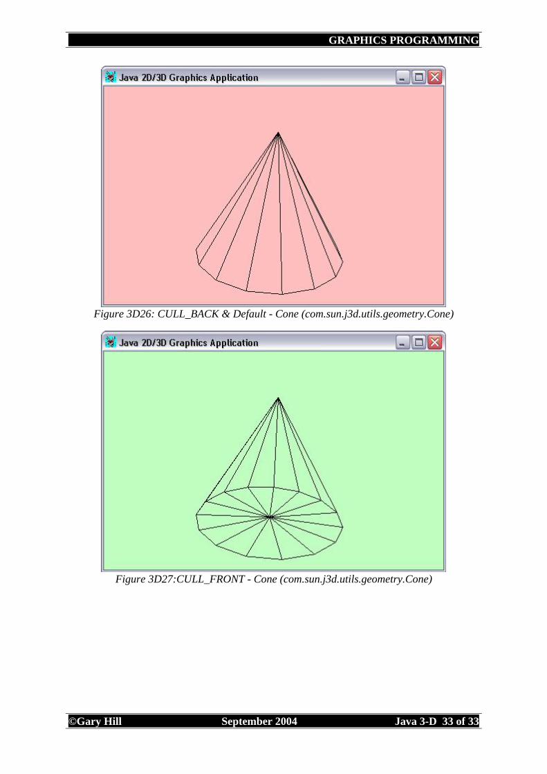
The PolygonAttributes used to define which polygons/faces are culled(discarded/removed) before they are converted to screen coordinates, has three options:
• CULL_BACK - culls all back-facing polygons. The default. • CULL_NONE - disables face culling. • CULL_FRONT - culls all front-facing polygons.
To use any of the above options it is best to create an instance of Appearance, as before, and use the setCullFace method for the PolygonAttributes instance: polyAttrib.setCullFace(PolygonAttributes.CULL_BACK); To illustrate the use of face culling a Cone is used (from the Sun utility classes (com.sun.j3d.utils.geometry, com.sun.j3d.utils.geometry.Cone) and POLYGON_LINE to create a black wire frame appearance.
Note: If your backround is set the default black you will need to change the line colouring to
Using the com.sun.j3d.utils.geometry primitive examples of Box, Cone, Cylinder and Sphere previously created, alter them to discover and appreciate the effect of the three setCullFace options.
ambientColor - the ambient colour affects all surfaces equally. It is an all round lighting. emissiveColor - the emissive colour is the light emitted from a surface similar to a glow. diffuseColor - the diffuse colour is light evenly reflected from the surface when illuminated by a light.
shininess - the material's shininess in a range [1.0, 128.0] 1.0 = not shiny and 128.0 = very shiny. The default Material constructor creates an object with the following paramaters:
Color3f takes three parameters of type float. These are for Red, Green & Blue:
Figure 3D31:sRGB standard Red, Green & Blue Colours (sun)
Some of the common colours, in Java 3D, are specified using combinations of Red Green and Blue (RGB) see below: Color3f white = new Color3f(1.0f, 1.0f, 1.0f); Color3f black = new Color3f(0.0f, 0.0f, 0.0f); Color3f red = new Color3f(1.0f, 0.0f, 0.0f); Color3f green = new Color3f(0.0f, 1.0f, 0.0f); Color3f blue = new Color3f(0.0f, 0.0f, 1.0f); Color3f yellow = new Color3f(1.0f, 1.0f, 0.0f); Color3f cyan = new Color3f(0.0f, 1.0f, 1.0f); Color3f magenta = new Color3f(1.0f, 0.0f, 1.0f); For a more detailed colour chart using RGB 0 to 1 (decimal) values see the following RGB.html
ColoringAttributes can, again, be used to set the colour of an object as previously:
Figure 3D32:ColoringAttributes
To see the effect of altering an objects Material properties there must be external lighting to see the object (unless emissive light is used which would have the effect of lighting the object in the dark). Lighting will be covered in the next section, which in turn will enable a greater appreciation of Material properties.
Again, using the com.sun.j3d.utils.geometry primitive examples of Box, Cone, Cylinder and Sphere previously created, alter them see how they are effected by either the ColoringAttributes or emissive coloured lighting.
Lights are covered in detail within Sun's Java 3D Tutorial - Chapter 6, Lights: Lightening up your scene and describing materials and colors, although lights are briefly discussed here. The four types of light source within Java 3D are:
| +--javax.media.j3d.SpotLight For lighting to be applied to a scene the following have to be present, otherwise the content/object will appear bright white. Light source details:
• set bounds (the boundary within which the light affects). • add to the scene graph
Content/Object
• normals (vectors perpendicular to its surfaces). • Material properties
AmbientLight
To introduce AmbientLight to a scene the following default code would be used:
The default constructor can be altered to incorporate the ambient light colour using the set method: AmbientLight ambientLight = new AmbientLight(); Color3f green = new Color3f(0.0f, 1.0f, 0.0f); ambientLight.setColor(green); The second constructor incorporates the ambient light colour when instantiated: Color3f green = new Color3f(0.0f, 1.0f, 0.0f); AmbientLight ambientLight = new AmbientLight(green); The first two constructors have the light set to 'on' as default. The Light can be set to 'on' or 'off' using: ambientLight.setEnabled(true); ambientLight.setEnabled(false); The BoundingSphere object defines a spherical bounding volume within which geometry objects are affected by a light source. This spherical boundery has two values: the center point and the radius of the sphere. This restricts the influence of lighting to a defined boundary (see also Bounds and BoundingLeaf).
• BoundingSphere(Point3d center, double radius) • BoundingSphere() • BoundingSphere(Bounds boundsObject)
Once a BoundingSphere is created the light source to which this has influence needs to be set using: BoundingSphere ambientBoundingSphere = new BoundingSphere(); ambientLight.setInfluencingBounds(ambientBoundingSphere);
DirectionalLight
To improve the lit scene DirectionalLight can be added to the scene with the default code:
The obvious difference for DirectionalLight from AmbientLight is the requirement for a Vector3f direction in which the light is shined toward the object. The default constructor has
lightOn set to true; color set to white (1.0f, 1.0f, 1.0f) and the direction as a Vector3f point from the light to the object as (0.0f, 0.0f, -1.0f). It may help to consider the direction as a light shining from the origin (0.0f, 0.0f, 0.0f) to the Vector3f as a point. Therefore (0.0f, 0.0f, -1.0f) would give a DirectionalLight shining straight onto the object as in Figure 3D33. The DirectionalLight default constructor can be altered to incorporate the light direction using the set method: Vector3f lightDirection = new Vector3f(-1.0f, -1.0f, -1.0f); directionalLight.setDirection(lightDirection); or directionalLight.setDirection(-1.0f, -1.0f, -1.0f);
Exercise 3D12: AmbientLight with DirectionalLight
Using the blue sphere (from Figure 3D30) with its original Material and Appearance determine the Vector3f values required for a DirectionalLight from the top right, top left, bottom left and bottom right (see figure below). Hint: Start with the Vector3f(-1.0f, -1.0f, -1.0f) and see the effect.
Figure 3D36: AmbientLight with DirectionalLight Top L, R and Bottom L, R.
PointLight
A PointLight radiates light equally in all directions away from the light source. PointLight has three constructors:
• PointLight() - Constructs a PointLight node with default parameters of position (0, 0, 0) and attenuation (1, 0, 0).
• PointLight(boolean lightOn, Color3f color, Point3f position, Point3f attenuation) - Constructs and initializes a point light.
• PointLight(Color3f color, Point3f position, Point3f attenuation) - Constructs and initializes a point light.
The main difference between the constructor for PointLight and that of DirectionalLight is the requirement for the attenuation and the position to both be given as Point3f. The position is simply the position of the light. The attentuation/weakening of the light is more complicated. Attenutation takes three parameters of the light for:
• Constant attenuation • Linear attenuation • Quadratic attenuation
These parameters make up the attenuation factor which causes the brightness of a PointLight to decrease as distance from the light source increases. A PointLight, therefore, is attenuated by the reciprocal of the sum of:
• The constant attenuation factor • The Linear attenuation factor times the distance between the light and the vertex
being illuminated • The quadratic attenuation factor times the square of the distance between the light and
the vertex
The default attentuation factor uses a constant attenuation value of 1 and the linear and quadratic values as 0. This results in no attenuation/weakness of the PointLight.
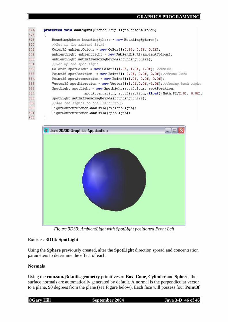
• SpotLight(Color3f color, Point3f position, Point3f attenuation, Vector3f direction, float spreadAngle, float concentration) - Constructs and initializes a SpotLight node using the specified parameters.
Figure 3D38: SpotLight (Sun)
A SpotLight extends PointLight and therefore has the same attributes as a PointLight node, with the addition of the following:
• Direction • Spread angle • Concentration
Direction - The axis of the cone of light. The default direction is (0.0, 0.0, -1.0). The spot light direction is significant only when the spread angle is not PI radians (which it is by default). Spread angle - The angle in radians between the direction axis and a ray along the edge of the cone. Note that the angle of the cone at the apex is then twice this value. The range of values is [0.0,PI/2] radians, with a special value of PI radians. Values lower than 0 are clamped to 0 and values over PI/2 are clamped to PI. The default spread angle is PI radians. Concentration - Specifies how quickly the light intensity attenuates as a function of the angle of radiation as measured from the direction of radiation. The light's intensity is highest at the center of the cone and is attenuated toward the edges of the cone by the cosine of the angle between the direction of the light and the direction from the light to the object being lit, raised to the power of the spot concentration exponent. The higher the concentration value, the more focused the light source. The range of values is [0.0,128.0]. The default concentration is 0.0, which provides uniform light distribution. Java 3D 1.3 API Documentation
Figure 3D39: AmbientLight with SpotLight positioned Front Left
Exercise 3D14: SpotLight
Using the Sphere previously created, alter the SpotLight direction spread and concentration parameters to determine the effect of each.
Normals
Using the com.sun.j3d.utils.geometry primitives of Box, Cone, Cylinder and Sphere, the surface normals are automatically generated by default. A normal is the perpendicular vector to a plane, 90 degrees from the plane (see Figure below). Each face will possess four Point3f
with the corresponding four normals which define the surface normal. These normals are then used to evaluate the lighting to determine which side of a face is rendered. Normals are defined using Vector3f which indicate the direction the object/face is facing. A Vector3f for a Point3f/face given as (0.0f, 0.0f, -1.0f) would mean that this surface was facing away/backwards from the origin (0.0f, 0.0f, 0.0f).
Figure 3D40: Surface normal Ray Optics, Light Reflection (id.mind.net)
IndexedQuadArray
To illustrate the inclusion of normals for created objects, the cube generated from IndexedQuadArray will be used. First an array of Vector3f normals would need to be defined, for which there are 6, one for each face. Then an array of indices for the Point3f coordinates defining each of the faces (24 in total). Finally the normals and normal indices are set to the cube/shape. See code below:
Remember that the second of the three parameters in the IndexedQuadArray, is vertexFormat which always includes COORDINATES, but can include a number of others parameters that can be OR'd ('|') together. The second parameter is where the normals are incorporated in the object created: IndexedQuadArray indexedShape = new IndexedQuadArray (8, IndexedQuadArray.COORDINATES|IndexedQuadArray.NORMALS, 24);
Figure 3D41: Normals, IndexedQuadArray with AmbientLight and DirectionalLight
positioned top right
Exercise 3D15: Normals & IndexedQuadArray
Using the IndexedQuadArray cube previously created, incorporate the surface normals as above. The lighting should be AmbientLight and DirectionalLight as in Exercise 3D12. Also the same Material properties should be used. Hint: Add one face at a time starting from the back face to see the affect of the normals.
The key classes used for transformations are TransformGroup and Transform3D. Both classes include a multitude of methods and as a result are versatile classes, therefore only a brief overview will be given here. Reference should be made to the Java 3D 1.3 API Documentation for more information. All the previous examples have used a transformation. The object in each of the examples was rotated slightly to help illustrate its 3D nature. The Scene Graph contains two TransformGroups, one for the content branch BranchGroup and the other for the view branch BranchGroup. Here we will concentrate on the former.
Figure 3D42: Application Scene Graph Model (sun)
The stages neccessary to create a transformation are as follows: Create a new BranchGroup and a new TransformGroup to contain the content. When the TransformGroup is created a Transform3D is passed to its constructor. This enables Transform3D to set any transformations that are to be carried out on the children of the TransformGroup. The TransformGroup is finally added to its parent (addChild) the content branch and the content (shape/s) are added (addChild) to the TransformGroup (See code below).
Therefore, the children of the TransformGroup will be the shapes. The TransformGroup acts as the container for any transformations. These transformations are instances of the Transform3D class. The Transform3D class enables the positioning and orientation of any shape/s within the usual 3D coordinate system. In turn a transformation within Transform3D is set using either AxisAngle4d(orAxisAngle4f) as above, and/or Vector3d (or Vector3f). AxisAngle4d(orAxisAngle4f) A four-element axis angle represented by double-precision floating point x, y, z, angle components. An axis angle is a rotation of angle (radians) about the vector (x, y, z). Java 3D, as with the 2D Graphics class AffineTransform, offers the ability to translate, rotate, scale or perform a combination (concatenation) of these manipulations on graphics:
• translate: specify a translation offset in the x, y and z directions. • rotate: specify an angle of rotation in radians about the x, y and/or z axis. • scale: specify a scaling factor in the x , y and z directions.
Tranform3D methods
setTranslation
setToTranslation takes 1 argument, the translation (offset) for all axes as a Vector3d (or Vector3f).
Figure 3D43: setTranslation 1m to the left (x = -1.0)
setRotation, rotX, rotY, rotZ
setRotation(AxisAngle4f) setRotation(Quat4f) setRotation(Matrix3f) takes 1 argument, the angle of rotation in radians (theta) as either a AxisAngle4f, Quat4f or Matrix3f. rotX(double), rotY(double) and rotZ(double) all take 1 argument, the angle of rotation in radians (theta) as a double.
Example using setRotation
Here setRotation will be demonstrated, however rotX, rotY & rotZ give greater flexibilty and control.
Figure 3D45: setScale to half in all directions (x = 0.5, y=0.5, z=0.5)
transform
setTransform takes 1 or 2 arguments. See Java 3D 1.3 API Documentation for more information.
Combining transformations
To combine (concatenate) more than one transform they can all be set one after the other. These can be set in any order, but the TransformGroup will, by default, apply them in the following order:
Remember that the transformations may be set in any order, but the TransformGroup will, by default, apply them in the following order:
• scale • rotation • translation
Figure 3D46: setTranslate, setRotation and setScale.
Exercise 3D16: Transform3D
Using the Box cube previously created, use the Tranform3D methods of setTranslation, setRotation, rotX, rotY, rotZ, and setScale to investigate the behaviour and implementation of each. Use the same Material, AmbientLight and DirectionalLight as in Exercise 3D12.
Animation is covered in detail within Sun's Java 3D Tutorial - Chapter 5 Animation. However, one of the texts recommended for this module is the Essential Java 3D fast and the publisher (Springer) have made available the Animation Chapter as a sample on their site. Therefore, this Chapter will be used for this section. The code for two of the three examples used in this Chapter are also available from the publishers web site. The examples are:
Interaction is covered in detail within Sun's Java 3D Tutorial - Chapter 4 Interaction.
Interaction with JButtons (AWT/Swing)
The simplest interaction to incorporate within Java 3D makes use of the standard AWT and Swing Button/JButton components. The type of Graphical User Interface GUI can be varied i.e. It would be possible to add a JMenuBar/JPopupMenu (with its associated JMenus and drop-down JMenuItems) or a JToolBar to an application to achieve the same interaction. However, there are known issues with the integration of Java 3D and Swing - the mixing of heavy and light-weight components (Integrating Java 3D and Swing, by Karl Meissner). The easiest way to combine the two is to add a Canvas3D to a JPanel. The example illustrated below allows the content to be rotated either clockwise (<LEFT) or anti-clockwise (RIGHT>). Obviously, the same affect could be achieved by rotating the view.
Note: JButton's are declared and created globally. BranchGroup contentBranch and the TransformGroup are also declared globally. import java.awt.event.*; //import the event listener public class G3DRotateCube extends JFrame implements ActionListener //implements ActionListener required to listern Amendment to lines 22 & 23 that removes the NULL warning at run time.
Behaviour, like Interaction, is covered in detail within Sun's Java 3D Tutorial - Chapter 4 Interaction. There are various types of behaviour that could be considered.
MouseBehavior
java.lang.Object | +--javax.media.j3d.SceneGraphObject | +--javax.media.j3d.Node | +--javax.media.j3d.Leaf | +--javax.media.j3d.Behavior | +--com.sun.j3d.utils.behaviors.mouse.MouseBehavior MouseBehavior and in particular its subclasses MouseRotate, MouseTranslate and MouseZoom enable mouse driven interaction. To demonstrate the use of MouseBehavior the previous example will be used.
• create a MouseBehavior object i.e. MouseRotate, MouseTranslate and MouseZoom
• set the target TransformGroup • set the scheduling bounds (or BoundingLeaf) for the MouseBehavior object • add the content to the MouseBehavior • add the MouseBehavior and TransformGroup objects to the scene graph
To incorporate all three of the behaviors MouseRotate, MouseTranslate and MouseZoom would require the following:
The required behaviours (MouseBehavior) are initiated by the user as follows:
• MouseRotate press, hold and move the left button, whilst moving the mouse. • MouseTranslate press, hold and move the right button, whilst moving the mouse. • MouseZoom press and hold the middle button or press and hold both Alt + the left
button, whilst moving the mouse.
KeyNavigatorBehavior
java.lang.Object | +--javax.media.j3d.SceneGraphObject | +--javax.media.j3d.Node | +--javax.media.j3d.Leaf | +--javax.media.j3d.Behavior | +--com.sun.j3d.utils.behaviors.keyboard.KeyNavigatorBehavior The type of movement and key presses required are shown in the figure below:
To demonstrate the use of KeyNavigatorBehavior the previous example will be used. The KeyNavigatorBehavior can be added to the content branch or view branch (as with all behaviours). First, the KeyNavigatorBehavior will be added to the content branch:
KeyNavigatorBehavior would be added to the view branch as follows:
Whilst Java 3D supports the inclusion of collision detection, usually a programmer is looking for collision prevention/avoidance, e.g. In games programming attempting to prevent the player walking through walls or objects. There are two ways of providing collision prevention. The simplest implementation builds upon the JButton (AWT/Swing) principle above.
Collision Prevention with JButtons (AWT/Swing)
The simplest collision prevention is limited in its application and is only practical in simple situations. The principle will be introduced here. To implement collision prevention it is necessary to look at the Transform3D class in more detail.
Transform3D
A Transform3D is created to perform transformations (translations, rotations, scaling, shearing) which is represented within Java 3D as a 4x4 double-precision floating point matrix: [ m00 m01 m02 m03 ] [ x ] [ x' ] [ m10 m11 m12 m13 ] . [ y ] = [ y' ] [ m20 m21 m22 m23 ] [ z ] [ z' ] [ m30 m31 m32 m33 ] [ w ] [ w' ] x' = m00 . x+m01 . y+m02 . z+m03 . w y' = m10 . x+m11 . y+m12 . z+m13 . w z' = m20 . x+m21 . y+m22 . z+m23 . w w' = m30 . x+m31 . y+m32 . z+m33 . w To access the Transform3D a System.out.println(transform3DInstance); moving from a view position of Z= -8.0f after 5 translations will give:
Figure 3D50: Collision Prevention on Blue Cube (1.0, 1.0, 1.0) from Figure 3D45.
Each time the 'forward' button is pressed the following translation takes place: tempDelta.setTranslation(new Vector3f(0.0f, 0.0f, -1.0f)); //[x] [y] [z] [w] The result of multiplying (mul) the original Transform3D by the new translation is to decrement the element relating to the z translation in position 2, 3 (row 2, column 3). To access this matrix the Transform3D method get(float[] matrix) can be used. This method will extract the elements of the Transform3D and place them in a single precision 16 element array. We need to access the 11th element of this array. See the code below for the final implementation:
Modify the program above to incorporate buttons to move up, down, left and right. Observe the effect of each of these movements. Which element in the Transform3D is altered?
Collision Detection
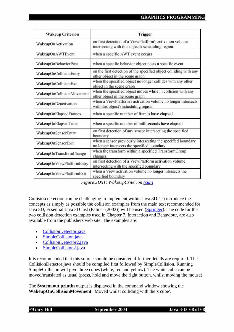
Java 3D supports inclusion of collision detection through the Java 3D Behavior node. There are three WakeupCriterion objects that can be used to activate a behavior:
Collision detection can be challenging to implement within Java 3D. To introduce the concepts as simply as possible the collision examples from the main text recommended for Java 3D, Essential Java 3D fast (Palmer (2002)) will be used (Springer). The code for the two collision detection examples used in Chapter 7, Interaction and Behaviour, are also available from the publishers web site. The examples are:
It is recommended that this source should be consulted if further details are required. The CollisionDetector.java should be compiled first followed by SimpleCollision. Running SimpleCollision will give three cubes (white, red and yellow). The white cube can be moved/translated as usual (press, hold and move the right button, whilst moving the mouse). The System.out.println output is displayed in the command window showing the WakeupOnCollisionMovement 'Moved whilst colliding with the x cube',
Another exercise demonstrating the use of collision detection is available from the demonstration programs installed with the Java 3D API. In the directory C:\j2sdk1.4.0_02\demo\java3d\TickTockCollision> is the TickTockCollision example. The programs uses the following three files:
Barrilleaux (2001) Chapter 13, section 13.3.4 (See Resources) Selman (2002) Section 16.8 (See Resources) Palmer (2002) Chapter 7 (See Resources) Couch (2002) Collision Detection System http://www.j3d.org/implementation/collision.html [Accessed 10/03/03] Couch (2002) Implementing Terrain Following and Collision Detection in Java 3D http://www.j3d.org/tutorials/collision/index.html [Accessed 24/03/03] Sun Java 3D Tutorial - Chapter 4 Interaction.
Figure 3D55: Creating a scene using translations: Box, Ground and Back Wall
Background
java.lang.Object | +--javax.media.j3d.SceneGraphObject | +--javax.media.j3d.Node | +--javax.media.j3d.Leaf | +--javax.media.j3d.Background To add a Background colour to a scene, the following code would need to be added to the view branch (of the scene graph):
Barrilleaux (2001) 3D User Interfaces with Java 3D, Chapter 8, Manipulation Barrilleaux (2001) 3D User Interfaces with Java 3D, Chapter 13, Actions and Interactions Barrilleaux (2001) 3D User Interfaces with Java 3D, Chapter 17, Control basics Barrilleaux (2001) 3D User Interfaces with Java 3D, Chapter 19, Control Intuition