E1 E32 STATE PROJECT SHEET TOTAL 1--~~-.:_-----11----PH_0_0_28-(3-7)-32_9 __ --I NO. SHEETS Section E: Structure Plans INDEX OF SHEETS - Sheet El Sheet E2 Sheet E3 to E7 Sheet EB to E15 Sheet E17 to E27 Sheet E28 to E32 Layout Map and Index Estimate of St,uctu,e Quantities St,. No. 29-077-150 2 - 12' x 5' Box Culve,t CP,ecast) St,. No. 29-082-150 10' x 7' Box Culve,t Str. No. 29-092-150 2 - 12' x 5' Box Culve,t St,. No. 29-115-150 3 - 10' x 9' Box Culve,t Extension CP,ecast) END SHOULDER WIDENING BEGIN GRADING END EXCEPTION Station 162+56.57 Station 324+25 BEGIN PH 0028 37 329 BEGIN EXCEPTION Station 160+49.52 Sta. 250 + 75.00 str. No. 29-115-150 3 - 10' x 9' Box Culvert Extension (Precast) Station 10+50 z rt) ..- ..- I- R55W R55W R54W END SHOULDER WIDENING BEGIN GRADING Station 254+25 END GRADING BEGIN SHOULDER WIDENING Station 264+66.00 END GRADING BEGIN SHOULDER WIDENING Station 335+50 N BEGIN EXCEPTION Station 435+12.00 R53W LAKE ST. R53W END SHOULDER WIDENING BEGIN GRADING Station 442+34.01 END GRADING BEGIN SHOULDER WIDENING Station 462+00.00 w CX) ..... ('") 14 0 Ol Ol + (") -q-- I!) w END EXCEPTION Station 440+66.00 R 52 W END PH 0028 37 329 R52W END GRADING Station 596+00 z (\') ..- ..- I- BEGIN SHOULDER WIDENING Station 516+00.00 END SHOULDER WIDENING BEGIN GRADING Station 479+50
460E0120 Class A45 Concrete, Box Culvert 306.2 CuYd
480E0100 Reinforcing Steel 42,330 Lb
700E0210 Class B Riprap 115.3 Ton
831E0110 Type B Drainage Fabric 161 SaYd
E3 E32The elevations shown in these plans are based on the National Geodetic Survey (NGS) North American Vertical Datum of 1988 (NA VDBB).
LEGEND
W = Width of Opening H = Height of Opening Tt = Thickness of Top Slab Tb = Thickness of Bottom Slab Ts = Thickness of Side Wall
12'-0"
* Dimension may vary with fabricator and/or installation. See Shop Plans for actual installation length. * Minimum distance to satisfy clear zone. 6 Based on dimensions shown. □ Based on 8" side walls and 8" middle wall.
NOTE: Box Culvert ffowline has been depressed 1' - O" below channel ffowline to accommodate aquatic organisms. The 1' - O" depression will be allowed to fill in naturally over time.
HYDRAULIC DA TA Qd 389 cfs
Ad 60sq. ft.
Vd 6.5 fps
QF 389 cfs
o,oo 660 cfs
Oar 873 cfs
Vmax 9.1 fps
6F. L. Elev. 1733.46
Qd = Design discharge for the proposed culvert based on 25 year frequency. El. 1738.4. Q0 r = Overlapping discharge and frequency> Q 100 year recurrence interval. El. 1741.3@ Sta. 46 + 43.00.
Q F = Designated peak discharge for the basin approaching proposed project based on 25 year frequency.
0 100 = Computed discharge for the basin approaching proposed project based on 100 year frequency. El. 1739.9.
V max = Maximum computed outlet velocity for the proposed culvert, based on 100 year frequency.
22'-0" 12.6: 1
Finished Shoulder Match Existing
=~;~, -= --:c ---- -
20'-0" Match Existing
PLAN
20'-0"
'1 · 't Finished Match Existing
20'-0" 22'-0" 2:1 Match Existing 14.9: 1
20'-0"
I H. W. Elev. 1739.9 (100 Year) ..,,,. I D.H.W Elev. 1738.4 (25 Year)
6 F. L. Elev. 1733. 55
F. L. Elev. 1733.50 ° Bottom Limits of Undercut 0:,
-------------------------w--------------, ELEVATION (See Typical Section on Notes
and Undercut Details Sheet.)
ESTIMATED QUANTITIES ITEM UNIT
Structure Excavation, Box Culvert Cu. Yd. Box Culvert Undercut Cu. Yd. Class B Riprap Ton Type B Drainage Fabric Sq. Yd. 2 - 12' X 5' Precast Concrete Box Culvert, Furnish Ft. 2 - 12' X 5' Precast Concrete Box Culvert, Install Ft. 2 - 12' X 5' Precast Concrete Box Culvert End Section, Furnish Each 2 - 12' X 5' Precast Concrete Box Culvert End Section, Install Each
tj. Quantity is based on 9" bottom slab, 9" top slab and B" walls.
* For estimating purposes only, a factor of 1.4 tons/cu. yd. was used to convert Cu. Yd. to Tons.
QUANTITY
77 241
53 67 80 80 2 2
-X028-
INDEX OF CULVERT SHEETS Sheet No. 1 - General Drawing and Quantities Sheet No. 2 - Notes and Undercut Details Sheet No. 3 - Details of Standard Plate No's. 460.02 & 560.01 Sheet No. 4 - Details of Standard Plate No's. 560.21 & 560.20 Sheet No. 5 - Details of Standard Plate No. 620. 16
PLANS BY: OFFICE OF BRIDGE DESIGN, SOUTH DAKOTA DEPARTMENT OF TRANSPORTATION
GENERAL DRAWING AND QUANTITIES
FOR
2 - 12' X 5' BOX CULVERT (PRECAST) OVER TRIB. TO DOLPH CREEK STA. 44 + 95.00 STR. NO. 29-077-150 PCN 04JY
2. Construction Specifications: South Dakota Standard Specifications for Roads and Bridges, 2015 Edition and required Provisions, Supplemental Specifications, and Special Provisions as included in the Proposal.
GENERAL NOTES Design shall be in accordance with Section 560 of the South Dakota Specifications with the following criteria:
1. Box culvert and box culvert end section design shall conform to the AASHTO LRFD Bridge Design Specifications, 8th Edition.
2. Design Live Load: HL-93. No construction loading in excess of legal load is anticipated. If construction loading in excess of legal load is anticipated by the Contractor, the Contractor will submit a proposal including a design analysis for the anticipated construction loading, through the proper channels, to the Office of Bridge Design for approval. Upon approval, the construction load will not be applied until the depth of fill over the box culvert as required by analysis has been placed. At a minimum, 4 feet of fill will be placed over the box culvert prior to applying the construction load All costs associated with accommodating any construction loads will be borne by the Contractor.
3. The box culvert shall be load rated in accordance with the AASHTO Manual for Bridge Evaluation, 2011 Edition with latest Interim Revisions using the LRFR method. The rating shall include evaluation of the Design HL-93 truck at both Inventory and Operating levels and a Legal Load rating for the three SD legal trucks (Type 3, 3S2 and 3-2) as well as the notional rating load and four specialized hauling vehicles. The structure shall also be evaluated for the emergency vehicles, EV2 and EV3, at the legal load rating level. All sections of the box culvert shall rate at HL-93 or better (Inventory Level). The three SD Legal Loads, the notional rating load, the four specialized hauling vehicles, and two emergency vehicles shall rate greater than 1. 0 at legal load rating level. Submit Load Rating calculations with the Design and Check Design calculations or shop plans, as appropriate.
4. The design of the barrel sections shall be based on a minimum fill height of 2 feet and include all subsequent fill heights up to and including the maximum fill height of 5 ft. over the box culvert.
5. Minimum inside comer fillet shall be 6 in.
6. Minimum precast barrel section length will be 6 foot sections; however, no more than two 4 foot sections are allowed in any one length of precast barrel.
7. Lift holes shall be plugged with an approved nonshrinkable grout.
8. The Fabricator shall imprint on the structure the date of construction as specified and detailed on Standard Plate No. 460.02.
9. Alternate end section details will be allowed, subject to the approval of the Bridge Construction Engineer. No additional payment will be made for any change in the barrel/end section configuration.
10. Installation of the precast sections shall be in accordance with the final approved shop plans.
11. Care shall be taken when placing sections. Sections shall be only moved using the lifting holes by approved equipment.
12. Dewatering will be required for construction of the box culvert.
SUBSURFACE INVESTIGATION (June 2019J
Station Offset Elevation Material Description
1740.4 - 1738.4 Gravel
44+85 19.0 ft R t. 1738.4 - 1734.9 Brown silt clay with sand
1734.9 - 1733.9 Gravel
1733.9 - 1721.4 Brown to Qray c lay si lt 1740.4 - 1738.4 Gravel 1738.4 - 1735.4 Brown silt clay with sand
45+05 19. 0 ft Lt. 1735.4 - 1734.4 Gravel
1734.4 - 1732.4 Black si lt clay (organics) 1732.4 - 1721.4 Brown to gray c lay si lt
DESIGN MIX OF CONCRETE
Groundwater
Elevation
1737. 1
1736.7
1. Mix shall be as per fabricator's design, however minimum compressive strength shall not be less than 4500 p.s.i. at 28 days.
2. Type II cement is required.
SHOP PLANS The fabricator shall submit shop plans in accordance with the specifications. Include design and check design, if applicable, with initial submittal.
6 b ""
b
6
I STATE I PROJECT I SHEET I TOTAL OF 1---------------1 NO. SHEETS
r/J For payment, quantity is based on plan shown undercut dimensions and will not be measured unless the Engineer orders a change.
NOTES AND UNDERCUT DETAILS
FOR
2 - 12' X 5' BOX CULVERT (PRECAST) OVER TRIB. TO DOLPH CREEK STA. 44 + 95.00 STR. NO. 29-077-150
0° SKEW SEC. 17/20-T113N-R54W
PH 0028(37)329 HL-93
HAMLIN COUNTY
S. D. DEPT. OF TRANSPORTATION
MAY 2018 0 OF 0 □Es1;5N0E□ BY I cK.~~s.Bv 1 □RAF8TTEDsvI4~,4~ ~ ~- _
HAML04JY 04JYGA02 I '"t<IDGE ENGINEER
E5 E32
¾" 1 ¼"
Year Plate See Note 2 (c)
17"
2½" 1" 2 ½" 1" 2½" 1" 2½"
g [OJ PLACE PLACE
APPROPRIATE APPROPRIATE
NUMBER NUMBER
HERE HERE
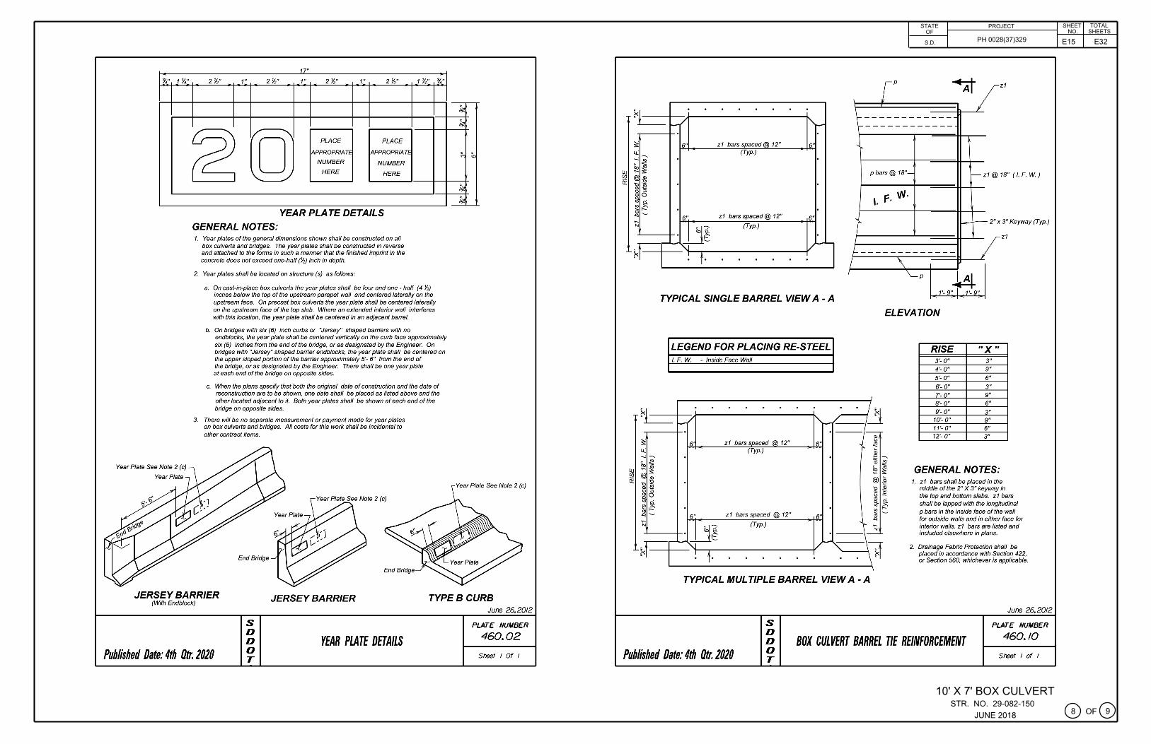
YEAR PLATE DETAILS
GENERAL NOTES: 1. Year plates of the general dimensions shown shall be constructed on all
box culverts and bridges. The year plates shall be constructed in reverse and attached to the forms in such a manner that the finished imprint in the concrete does not exceed one-half(½) inch in depth.
2. Year plates shall be located on structure (s) as follows:
1 ¼"
a. On cast-in-place box culverts the year plates shall be four and one - half (4 1/2) inches below the top of the upstream parapet wall and centered laterally on the upstream face. On precast box culverts the year plate shall be centered laterally on the upstream face of the top slab. Where an extended interior wall interferes with this location, the year plate shall be centered in an adjacent barrel.
b. On bridges with six (6) inch curbs or "Jersey" shaped barriers with no
¾"
endb/ocks, the year plate shall be centered vertically on the curb face approximately six (6) inches from the end of the bridge, or as designated by the Engineer. On bridges with "Jersey" shaped barrier endb/ocks, the year plate shall be centered on the upper sloped portion of the barrier approximately 5'- 6" from the end of the bridge, or as designated by the Engineer. There shall be one year plate at each end of the bridge on opposite sides.
c. When the plans specify that both the original date of construction and the date of reconstruction are to be shown, one date shall be placed as fisted above and the other located adjacent to it. Both year plates shall be shown at each end of the bridge on opposite sides.
3. There will be no separate measurement or payment made for year plates on box culverts and bridges. All costs for this work shall be incidental to other contract items.
End Bridge
End Bridge
~
~
1--: ~
~
~
Year Plate See Note 2 (c)
JERSEY BARRIER (With Endblock)
JERSEY BARRIER TYPEBCURB
Published Date: 4th Otr. 2020
s D D 0 T
YEAR PLATE DETAILS
June 26.2012
PLATE NUMBER
460.02
Sheet I Of I
Cf Hofe
I 16" 16" ·r~~,.
2" long 1 ½" ¢ (nominal pipe size) double extra strong pipe sleeve or approved equal. (Typ.)
STATE OF
S.D.
I. ~t~ 32" (Adj. ± 1 ½" Min.)
TIE BOLT ASSEMBLY
GENERAL NOTES: 1. All holes for tie bolts shall be cast-in-place, 16 inches from
outside edge of joint. Cast in inserts or sleeves, if used, shall be made of a corrosion resistant material.
2. Ties shall be 1 inch C1S and conform to the requirements of ASTM A36, ASTM A307, or ASfM Ft 554, Gr. 36. Nuts shall be heavy hex in conformance with ASTM A563. Washers shall conform to ASTM F436, Type 1. The welded pipe sleeve shall conform to ASTM A53, Grade B.
3. Welding and weld inspection shall be in conformance with AWSIANSI 01 .1 - (Current Year) Structural Welding Code - Steel.
4. Tie Bolt Assembly shall be galvanized in accordance with ASTM A 153 or ASTM F2329 as applicable.
5. Tie Bolt Assembly details may va,y from that shown, but alternate tie bolt assemblies are subject to testing to demonstrate equal strength. Submit details, through proper channels, to the Office of Bridge Design for approval.
6. All costs for furnishing and instaffing the precast box culvert tie bolt assembly shall be incidental to the contract unit price per Foot for "Precast Concrete Box Culvert, Furnish".
Published Date: 4th Otr. 2020
s D D 0 T
PRECAST BOX CULVERT TIE BOLT ASSEMBLY DETAILS
Cf Hofe
. I
PROJECT
PH 0028(37)329
March 21, 2016
PLATE NUMBER
560.01
Sheet I of I
SHEET TOTAL NO. SHEETS
2 - 12' X 5' BOX CULVERT (PRECAST)
G)oFG) STR. NO. 29-077-150
MAY 2018
E6 E32
1"¢ Tie (Typ.)
PLAN (Inlet or Outlet)
ELEVATION (Inlet or Outlet)
Tm
' ' ' ' ' ' ' ' ' ' ai : -----~--~ ===~=a::!
)( ' -----o·--, Ill :
' ' ' ' ' ' ' '
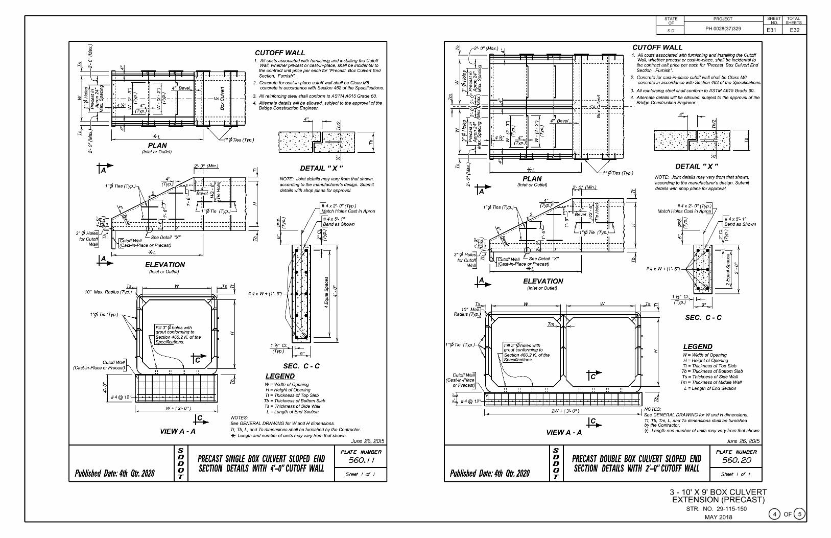
CUTOFF WALL 1. All costs associated with furnishing and installing the Cutoff
Wall, whether precast or cast-in-place, shall be incidental to the contract unit price per each for "Precast Box Culvert End Section, Furnish".
2. Concrete for cast-in-place cutoff wall shall be Class M6 concrete in accordance with Section 462 of the Specifications.
3. All reinforcing steel shall conform to ASTM A615 Grade 60.
4. Alternate details will be allowed, subject to the approval of the Bridge Construction Engineer.
4" r
DETAIL "X " 1"¢Ties (Typ.)
NOTE: Joint details may vary from that shown, according to the manufacturer's design. Submit details with shop plans for approval.
:i::
w
~
1 ½" Cl. I---
~ SEC. C-C
LEGEND W = Width of Opening H = Height of Opening Tt = Thickness of Top Slab
Tb = Thickness of Bottom Slab Ts = Thickness of Side Wall
Tm = Thickness of Middle Wall
L = Length of End Section
I 2W + ( 3'- O") I NOTES: ,--.,------------~-~----------..,,..., See GENERAL DRAWING for Wand H dimensions.
VIEW A-A
Tt, Tb, Tm, L, and Ts dimensions shall be furnished by the Contractor. * Length and number of units may vary from that shown.
June 26. 2015
PLATE NUMBER
560.20
Published Date: 4th Otr. 2020
s D D 0 T
PRECAST DOUBLE BOX CULVERT SLOPED END SECTION DETAILS WITH 2'-0" CUTOFF WALL
Sheet I of I
~ri __ _ ~ f--------'*-'-'L=---------"
0 PLAN ~ (Inlet or Outlet)
tr
~ID 3" ¢Holes ,J"
for Cutoff ~ I Wall
ELEVATION
10" M Radius (T
Ts
~ yp. 11y ~
1"¢Tie (Typ ,, . II CutoffWa
(Cast-in-Plac orPrecas
e t)
12" E . '
\
(Inlet or Outlet)
w
Tm'<_
Fifi 3" ¢ holes with grout conforming to ~
\ Section 460.2 K. of the ~lions.
~ ~
" " " "
1/
"
' ' ' ' ' ' ' ' ' ~ : -----< -~ ==~~8 :=:
----- ~--~ Ill :
w
~ "
' ' ' ' ' ' ' ' I '
" "
STATE OF
S.D.
PROJECT
PH 0028(37)329
CUTOFF WALL 1. All costs associated with furnishing and installing the Cutoff
Wall, whether precast or cast-in-place, shall be incidental to the contract unit price per each for "Precast Box Culvert End Section, Furnish".
2. Concrete for cast-in-place cutoff wall shall be Class M6 concrete in accordance with Section 462 of the Specifications.
3. All reinforcing steel shall conform to ASTM A615 Grade 60.
4. Alternate details will be allowed, subject to the approval of the Bridge Construction Engineer.
:i::
"( I
/
DETAIL "X " NOTE: Joint details may vary from that shown, according to the manufacturer's design. Submit details with shop plans for approval.
"' <l> 0
"' ~ ~ cii :,
r~i ,z ...
~= •
~=- :c:
•
~ . )
d
1 ½" Cl. I--
~ SEC. C-C
LEGEND W = Width of Opening H = Height of Opening Tt = Thickness of Top Slab
Tb = Thickness of Bottom Slab Ts = Thickness of Side Wall
Tm = Thickness of Middle Wall
NOTES: L = Length of End Section
I 2W + (3'- O") I i--•------------~--~-------------t See GENERAL DRAWING for Wand H dimensions.
Published Date: 4th Otr. 2020
Tl, Tb, Tm, L, and Ts dimensions shall be furnished by the Contractor.
VIEW A-A * Length and number of units may vary from that shown.
June 26. 2015
s D D 0 T
PRECAST DOUBLE BOX CULVERT SLOPED END SECTION DETAILS WITH 4'-0" CUTOFF WALL
PLATE NUMBER
560.21
Sheet I of I
SHEET TOTAL NO. SHEETS
2 - 12' X 5' BOX CULVERT (PRECAST)
0oFG) STR. NO. 29-077-150
MAY 2018
E7 E32
Eyebolt (See EYEBOL T DETAILS)
x--x--x--x x--x--x--x ==~~:.._ ______ _
- " x--:----"I,. "
Flowline Box Culvert
' ·-- _.J
DETAIL FOR FENCE ANCHORS
GENERAL NOTES:
1. The fence and post details shown are for illustrative purpose only. The fence shall be as specified elsewhere in the plans.
2. Eyeballs shall be placed on all of the box culvert wing walls.
3. Eyeballs shall be r,, inch diameter and shall conform to AS TM A307. VIEWA -A 4. Eyeballs, nuts, and concrete inserts shall be galvanized in accordance
with AASHTO M232 (ASTM A 153). Concrete inserts of corrosion resistant material need not be galvanized. Len th of E ebolt
5. Cast-in-place eyebolts shall have a nut attached, be 4 ½ inches (Min.) in length and shall be embedded such that the eye of the bolt is flush with the concrete surface. (See Eyeball Details) As an alternate, cast-in-place concrete inserts, capable of developing the full strength of the r,, inch diameter threaded eyeball, may be used and shall be set in the concrete in accordance with the manufacturer's recommendations. The eyeball shall be of sufficient length to develop its full strength. The eye of the eyebolt shall be flush with the concrete surface.
6. The cost for furnishing and instaffing eyeballs and/or concrete inserts shall be incidental to various contract items. EYEBOL T DETAILS
Published Date: 4th Otr. 2020
s D D 0 T
FENCE ANCHORS FOR BOX CULVERT WING WALLS
December 23.2012
PLATE NUMBER
620.16
Sheet I of I
STATE OF
S.D.
PROJECT
PH 0028(37)329
SHEET TOTAL NO. SHEETS
2 - 12' X 5' BOX CULVERT (PRECAST)
G)oFG) STR. NO. 29-077-150 MAY 2018
E8 E32The elevations shown in these plans are based on the National Geodetic Survey (NGS) North American Vertical Datum of 1988 (NAVD88).
NOTE: Box culvert flow line has been depressed 1' - O" below channel flow line to accommodate aquatic organisms. The 1' - O" depression will be allowed to fill in naturally over time.
H. W. Elev. 1730.7 (100 Year)~
D.H.W. Elev. 1728.5 (25 Year)~ .,... .,...
\\
I
I I
I
~--'l:::::c:!:::::=====r---f-!-L------1 -
PLAN
23' - 1 Ye"
62'-9"
F5 = 48' - 0"
I
,?, F "'11:r
/ 1 Finished Shoulder~
1'- 1 ¼"
, (See Typical Section on Notes / i ~i' / jop Limits of Undercut. 1
Structure Excavation, Box Culvert Cu. Yd. Box Culvert Undercut Cu. Yd. Type B Drainage Fabric Sq. Yd. Class B Riprap Ton * For estimating purposes only, a factor of 1.4 tons/cu. yd. was
used to convert Cu. Yds. to Tons.
PLANS BY:
128.6
21711
51 207 77
62.0
16'-0"
OFFICE OF BRIDGE DESIGN, SOUTH DAKOTA DEPARTMENT OF TRANSPORTATION
STATE OF
S.D.
PROJECT
PH 0028(37)329
00
INDEX OF CULVERT SHEETS-sheet No. 1 - General Drawing and Quantities Sheet No. 2 - Notes and Undercut Details Sheet No. 3 - Inlet Details (A) Sheet No. 4 - Inlet Details (B)
Sheet No. 5 - Outlet Details (A) Sheet No. 6 - Outlet Details (B) Sheet No. 7 - F5 Barrel End Section Details (48' - 0'? Sheet No. 8 - Details of Standard Plate No's 460.02 and 460.10
Sheet No. 9 - Details of Standard Plate No. 620.16
SHEET TOTAL NO. SHEETS
GENERAL DRAWING AND QUANTITIES
FOR
10' X 7' BOX CULVERT OVER TRIB. TO DOLPH CREEK STA. 73 + 84.00 STR. NO. 29-082-150 PCN 04JY
30° RHF SKEW SEC. 16/21-T113N-R54W
PH 0028(37)329 HL-93
HAMLIN COUNTY
S. D. DEPT. OF TRANSPORTATION
JUNE 2018 0 OF 0 DESIGNED BY CK. DES. BY DRAFTED BY
2. Construction Specifications: South Dakota Standard Specifications for Roads and Bridges, 2015 Edition and required Provisions, Supplemental Specifications, and Special Provisions as included in the Proposal.
GENERAL NOTES 1. Design Live Load: HL-93. No construction loading in excess oflegal load was
considered.
2. The design of the barrel section is based on a minimum fill height of 2 foot and includes all subsequent fill heights up to and including the maximum fill height of 5 ft. (F5).
3. Design Material Strengths: Concrete re = 4500 p.s.i. Reinforcing Steel fy = 60000 p.s.i.
4. High sulfate levels are likely to be encountered on this project. All concrete shall be Class A45 conforming to section 460, with the following modifications: the type of cement shall be either a type Vora type II with 20 to 25 percent Class F Modified Fly Ash substituted for cement in accordance with section 605.
5. All reinforcing steel shall conform to ASTM A615 Grade 60.
6. All lap splices shown are contact lap splices unless noted otherwise.
7. All exposed edges shall be chamfered¾ inch.
8. Use 1 inch clear cover on all reinforcing steel EXCEPT as shown.
9. The Contractor shall imprint on the structure the date of construction as specified and detailed on Standard Plate No. 460.02.
10. Care shall be taken to establish Working Points (WP.) as shown on the wings.
11. Circled numbers in PLAN and ELEVATION views on the General Drawing are section I.D. Numbers (see SDDOT Materials Manual).
12. Cost of Preformed Expansion Joint Filler used in apron construction will be incidental to the other contract items.
13. Dewatering will be required to construct the box culvert.
SUBSURFACE INVESTIGATION (June 2019)
Elevation Material Description Groundwater
Station Offset Elevation
1730.2 - 1726.7 Gravel
73+36 18.0ftLt. 1726.7 - 1724.2 Black silt clay (organics)
PLAN (Outlet End shown, Inlet End similar by rotation.)
p50orp60 t-t-------1@18"
k--+--+...-+-r---h5
ELEVATION
,- -
-,- -
~
,- -,- -
~ p50 orp60
'"""
k5
1c ¼-II
~ ~ p50 orp60
co (§) 0) ., '-' "' ~
O')
-,... -,...
'"""
n0-10 Sp. 6" @ 6" = 5' - 0"
6" m0 - 11 Spaces @6"= 5'-6"
18" j0 - 2 Spaces
@18"=3'-0"
1'-1 ¼"
h5
LEGEND FOR PLACING RE-STEEL T. T.S. - Top of Top Slab
B. T.S. - Bottom of Top Slab T.B.S. - Top of Bottom Slab
B.B.S. - Bottom of Bottom Slab O.F. W. - Outside Face of Wall
I.FW. - Inside Face of Wall
OPTIONAL FILLET DETAIL ( At Bottom Slab)
NOTE: Contractor may form the optional full fillet, with 2" Chamfer, as detailed. The cost of the additional concrete shall be borne by the Contractor.
OPTIONAL POUR - BOTTOM SLAB The Bottom Slab may be poured continuously, at the option of the Contractor, with the use of a Preformed Metal keyway conforming to the keyway dimensions and location as shown on the plans. The keyway length shall be full width of the bottom slab. Care shall be taken to maintain proper alignment of the keyway during the pour sequence. All additional costs of this option shall be borne by the Contractor.
t:,. Place z1 bars thru construction joint between barrel sections as shown on Standard Plate No. 460. 10. Quantity of z1 bars are for one construction joint.
11' - 2"
10'-0"
8 Spaces@ 12" = 8' - 0" ·1· ,.:1::1
k5
p50orp60
6" 9 Spaces@ 12" = 9' - 0" (Typ.) 6"
2'-1" 8 Spaces@ 12" = 8' - 0" 2'- 1"
12'-2"
F5 BARREL HALF SECTION (5' - 0" Maximum Fill)
r/J
r/J
r/J
r/J
t:,.
STATE OF
PROJECT SHEET TOTAL NO. SHEETS
S.D. PH 0028(37)329
REINFORCING SCHEDULE For 2 - F5 Barrel End Sections
Mk. No. Size Len th T e Bending Details
h5 224 4 8'-9" 17A
6 4 11' - 3" Str. j0 j5 124 4 10' -0" Str.
p55 45' - 8" 50' - 10"
tll I • • I • • I k5 334 5 mo 12 6 m5 182 6
no 11 6 n5 182 6
13' -3" 17 12'-3" Str. 12' - 0" Str.
12' -3" Str.
11' - 0" Str. t,1 _,,,._ rn; I.,,._,: I p50 24 4 45'-0" Str. p55 38 4 96'-6" Str. p60 24 4 51' -3" Str. mo - ., - 2 1' 4 ½" 10' 10 ½" z1 28 5 3'-6" Str.
no 1' - 9" 10'-6"
j0 3'-0" 8'-3" 2'- 7" k5
0 I • • I 0 E: c::
~ -,... -"i[ :i :i
~i (.) (.)
O')
:i (.)
j0 8'-3" 3'-0"
no 10'- 6" 1' - 9"
Type 17 mo 10'-10 ½" 1' -4 ½"
L ~~ I ,2'-7'; lk5
(Typ.)
l~Oflh5 Type 17A
OPTIONAL k5 SPLICE DETAIL
Contractor may use optional reinforcing steel splice, as shown. The cost of the additional reinforcing steel shall be borne by the Contractor.
NOTES:
All dimensions are out to out of bars.
r/J See cutting diagram.
Request for additional reinforcing steel splices at points other than those shown, must be submitted to the Engineer for prior approval. If additional splices are approved, no payment will be allowed for the added quantity of reinforcing steel.
EST/MA TED QUANTITIES ClassA45 Reinforcing
ITEM Concrete, Steel Box Culvert
UNIT Cu.Yd. Lb.
2 - F5 Barrel End Sections 48'-0" 87.9 17604 1 - Construction Joint 102
Structure Excavation, Box Culvert
Cu.Yd.
28.8
F5 BARREL END SECTION DETAILS (48' - O")
FOR
10' X 7' BOX CULVERT OVER TRIB. TO DOLPH CREEK STA. 73 + 84.00
30° RHF SKEW SEC. 16/21-T113N-R54W
PH 0028(37)329 HL-93
STR. NO. 29-082-150 PCN 04JY
HAMLIN COUNTY
S. D. DEPT. OF TRANSPORTATION
JUNE 2018 0 OF 0 DESIGNED BY CK. DES. BY DRAFTED BY
CL CH BT HAML04JY 04JYGB07
E15 E32
¾" 1 ¼"
Year Plate See Note 2 (c)
17"
2½" 1" 2 ½" 1" 2½" 1" 2½"
g [OJ PLACE PLACE
APPROPRIATE APPROPRIATE
NUMBER NUMBER
HERE HERE
YEAR PLATE DETAILS
GENERAL NOTES: 1. Year plates of the general dimensions shown shall be constructed on all
box culverts and bridges. The year plates shall be constructed in reverse and attached to the forms in such a manner that the finished imprint in the concrete does not exceed one-half(½) inch in depth.
2. Year plates shall be located on structure (s) as follows:
1 ¼"
a. On cast-in-place box culverts the year plates shall be four and one - half (4 1/2) inches below the top of the upstream parapet wall and centered laterally on the upstream face. On precast box culverts the year plate shall be centered laterally on the upstream face of the top stab. Where an extended interior wall interferes with this location, the year plate shall be centered in an adjacent barrel.
b. On bridges with six (6) inch curbs or "Jersey" shaped barriers with no
¾"
endb/ocks, the year plate shall be centered vertically on the curb face approximately six (6) inches from the end of the bridge, or as designated by the Engineer. On bridges with "Jersey" shaped barrier endb/ocks, the year plate shall be centered on the upper sloped portion of the barrier approximately 5'- 6" from the end of the bridge, or as designated by the Engineer. There shall be one year plate at each end of the bridge on opposite sides.
c. When the plans specify that both the original date of construction and the date of reconstruction are to be shown, one date shall be placed as fisted above and the other located adjacent to it. Both year plates shall be shown at each end of the bridge on opposite sides.
3. There will be no separate measurement or payment made for year plates on box culverts and bridges. All costs for this work shall be incidental to other contract items.
End Bridge
End Bridge
~
~
1-, ~
=-~
~
Year Plate See Note 2 (c)
JERSEY BARRIER (With Endblock)
JERSEY BARRIER TYPEBCURB
Published Date: 4th Otr. 2020
s D D 0 T
YEAR PLATE DETAILS
June 26.2012
PLATE NUMBER
460.02
Sheet I Of I
t=------s: u:
. ------ "'
6" z1 bars spaced@ 12" (Typ.)
6'
LU ~ i (/)
ii
z1 bars spaced@ 12" 6" (Typ.)
TYPICAL SINGLE BARREL VIEW A - A
LEGEND FOR PLACING RE-STEEL I. F. W - Inside Face Wall
t=------6' z1 bars spaced @ 12"
(Typ.)
z1 bars spaced @ 12"
(Typ.)
I
\ [
p
STATE OF
S.D.
\--------------~------------
,-.
pbars@ 18"-
,. F. ""· "
I I
A
I
-
PROJECT
PH 0028(37)329
z1
-z1@
- 2" X
18" ( /. F. W. )
3" Keyway (Typ.)
z1
!--------------I \
\__p w 1'-9" I 1'-9"
7
ELEVATION
RISE ,, X,,
3'- O" 3" 4'- O" 9"
5'- O" 6"
6'- O" 3" 7'- O" 9"
8'-0" 6"
9'-0" ~" 10'- O" 9" 11'- O" 6" 12'- O" 3"
GENERAL NOTES: 1. z1 bars shall be placed in the
middle of the 2" X 3" keyway in the top and bottom slabs. z1 bars shall be lapped with the longitudinal p bars in the inside face of the wall for outside walls and in either face for interior walls. z1 bars are listed and included elsewhere in plans.
2. Drainage Fabric Protection shall be placed in accordance with Section 422, or Section 560, whichever is applicable.
1. The fence and post details shown are for illustrative purpose only. The fence shall be as specified elsewhere in the plans.
2. Eyeballs shall be placed on all of the box culvert wing walls.
3. Eyeballs shall be r,, inch diameter and shall conform to AS TM A307. VIEWA -A 4. Eyeballs, nuts, and concrete inserts shall be galvanized in accordance
with AASHTO M232 (ASTM A 153). Concrete inserts of corrosion resistant material need not be galvanized. Len th of E ebolt
5. Cast-in-place eyebolts shall have a nut attached, be 4 ½ inches (Min.) in length and shall be embedded such that the eye of the bolt is flush with the concrete surface. (See Eyebolt Details) As an alternate, cast-in-place concrete inserts, capable of developing the full strength of the r,, inch diameter threaded eyebolt, may be used and shall be set in the concrete in accordance with the manufacturer's recommendations. The eyeball shall be of sufficient length to develop its full strength. The eye of the eyebolt shall be flush with the concrete surface.
6. The cost for furnishing and instaffing eyeballs and/or concrete inserts shall be incidental to various contract items. EYEBOL T DETAILS
Published Date: 4th Otr. 2020
s D D 0 T
FENCE ANCHORS FOR BOX CULVERT WING WALLS
December 23.2012
PLATE NUMBER
620.16
Sheet I of I
STATE OF
PROJECT
S.D. PH 0028(37)329
1 O' X 7' BOX CULVERT STR. NO. 29-082-150
JUNE 2018
SHEET TOTAL NO. SHEETS
G)oFG)
E17 E32The elevations shown in these plans are based on the National Geodetic Survey (NGS) North American Vertical Datum of 1988 (NAVD88).
12'-0"
71'-8½"
13'-8½" F5 = 38'-0" (Outlet)
138'-2 ¼"
F5 = 40'-0"
20'-0" Offset
66'-5¾"
F5 = 38'-0"
ee Typical Section on Notes d Undercut Details sheet.)
Sheet No. 7 - F5 Baffel End Section Details (38' - 0'? (A) Sheet No. 8 - F5 Barrel End Section Details (38' - 0'? (B) Sheet No. 9 - F5 Barrel Interior Section Details (40' - 0'? Sheet No. 10 - Details of Standard Plate No's 460.02 and 460.10
Sheet No. 11 - Details of Standard Plate No. 620. 16
NOTE: Box culvert flow line has been depressed 1' - O" below channel flow line to accommodate aquatic organisms. The 1' - O" depression will be allowed to fill in naturally over time.
HYDRAULIC DATA Qd = Design discharge for the proposed culvert based on 25 year frequency. El. 1695.0. Qd
Ad
Vd
QF
Q,oo
QOT
Vmax
512 cfs
97 sq. ft.
5.3 fps
512 cfs
872 cfs
>Qsoo yr
6.5 fps
Q0 T = Overlapping discharge and frequency> Q500 yr. recurrence interval. El. 1697.6@Sta. 126 + 64.00.
QF = Designated peak discharge for the basin approaching proposed project based on 25 year frequency.
Q100 = Computed discharge for the basin approaching proposed project based on 100 year frequency. El. 1695.8.
V max = Maximum computed outlet velocity for the proposed culverl based on a 100 year frequency.
2. Construction Specifications: South Dakota Standard Specifications for Roads and Bridges, 2015 Edition and required Provisions, Supplemental Specifications, and Special Provisions as included in the Proposal.
GENERAL NOTES 1. Design Live Load: HL-93. No construction loading in excess of legal load was
considered .
2. The design of the barrel section is based on a minimum fill height of 2 foot and includes all subsequent fill heights up to and including the maximum fill height of 5 ft. (F5).
3. Design Material Strengths: Concrete re = 4500 p.s.i. Reinforcing Steel fy = 60000 p.s.i.
4. All concrete will be Class A45 conforming to Section 460 of the Construction Specifications.
5. All reinforcing steel will conform to ASTM A615 Grade 60.
6. All lap splices shown are contact lap splices unless noted otherwise.
7. All exposed edges will be chamfered¾ inch unless noted otherwise in the plans.
8. Use 1 inch clear cover on all reinforcing steel EXCEPT as shown.
9. The Contractor will imprint on the structure the date of construction as specified and detailed on Standard Plate No. 460. 02.
10. Care will be taken to establish Working Points (WP.) as shown on the wings.
11. Circled numbers in PLAN and ELEVATION views on the General Drawing are section I.D. Numbers (see SDDOT Materials Manual).
12. Cost of Preformed Expansion Joint Filler used in apron construction will be incidental to the other contract items.
13. Dewatering will be required to construct the box culvert.
r/J
SUBSURFACE INVESTIGATION (June 2019)
Station Offset Elevation Material Description Grounm<ater
OPTIONAL k5 SPLICE DETAIL Contractor may use optional reinforcing steel splice, as shown. The cost of the additional reinforcing steel shall be bome by the Contractor.
no 1'-3½" 24' 8½" -
mo 1'-4 ½" 25'- 7 ½"
j0 1'-7½" 23' - 7 ½"
Q, c:, E
c:, <:
~~E L j0 23'-7½" 1'- 7 ½"
mo 25'-7½" 1'-4 ½"
no 24'-8 ½" 1'-3 ½"
0J "" "' "' IO IO
a a a
p22 39' - 3" 50' - 3"
p111 :26•-9--: I: 37•_9 .. : I
E'.,_j ~ p11 37'-9"
p22 50' - 3" Type S11A
NOTES: r/J See cutting diagram. All dimensions are out to out of bars.
Request for additional reinforcing steel splices at points other than those shown, must be submitted to the Engineer for prior approval. If additional splices are approved, no payment will be allowed for the added quantity of reinforcing steel.
ESTIMATED QUANTITIES
26'-9"
39' - 3"
ClassA45 Reinforcing ITEM Concrete,
Box Culvert Steel
UNIT Cu.Yd. Lb.
2 - F5 Barrel End Sections @ 38' - 0" 176.6 24759
LEGEND FOR PLACING RE - STEEL O.F.O.W. - Outside Face of Outside Wall
I.F. 0. W. - Inside Face of Outside Wall M. W. - Middle Wall
Structure Excavation, Box Culvert
Cu.Yd.
75.3
F5 BARREL END SECTION DETAILS (38' - O") (B)
FOR
2 - 12' X 5' BOX CULVERT OVER TRIB. TO DOLPH CREEK STA. 126 + 93.00
Note: Contractor may form the optional full fillet, with 2" Chamfer, as detailed. The cost of the additional concrete shall be borne by the Contractor.
t:,.Place z1 bars thru construction joint between barrel sections as shown on Standard Plate No. 460. 10. Number of z1 bars shown is for 2 construction joints.
FS BARREL HALF SECTION SECTION (5' - 0" Maximum Fill)
t:,.
Mk. No.
h5 92 j5 80 k5 138 m5 87 n5 87
p5 121 s5 78 w5 46 z1 114
STATE OF
SD.
PROJECT
PH 0028(37)329
SHEET TOTAL NO. SHEETS
REINFORCING SCHEDULE Size Len h
4 7' - 3"
6 24'-6"
4 11' - O"
4 26'-6"
5 25'-6"
4 39'-9"
6 6'-9"
4 15' -9"
5 3'-6"
L
Type
17A Str. 17
Sir. Str. Str. Str.
S11A
Str.
Bending Details
I r-ot: l(Typ.)
OPTIONAL k5 SPLICE DETAIL Contractor may use optional reinforcing steel splice, as shown. The cost of the additional reinforcing steel shall be borne by the Contractor.
_u:_J hM ~FJ-Ir" o:, al (Exact)
2'-0W k5
I' · I Type 17A ~