SECTION I INTRODUCTION AND DESCRIPTION 1-1 INTRODUCTION We are pleased to have you as a Bush Hog cus- tomer. Your Model 2415 Flex Wing Rotary Cutter has been carefully designed to give maximum ser- vice with minimum down time. This manual is pro- vided to give you the necessary operating and main- tenance instructions for keeping your rotary cutter in top operating condition. Please read this manual thoroughly. Understand what each control is for and how to use it. Observe all safety precautions decaled on the machine and noted throughout the manual for safe operation of implement. If any assistance or additional information is needed, con- tact your authorized Bush Hog dealer. NOTE All references made in this manual to right, left, front, rear, top or bottom is as viewed facing the direction of forward travel with implement properly attached to tractor. 1-2 DESCRIPTION The Model 2415 Rotary Cutter (Figure 1-1) consists of a center unit with two variable position wings together having a cutting width of 15 feet (4.5m). Wing operating angles and machine cutting height are independently controlled using hydraulic cylin- ders. A self-leveling linkage maintains a level cutter at all cutting heights. Power from the tractor PTO is split at the center gearbox and supplied to each of the blade gearboxes. Each blade gearbox has two free-swinging uplift blades designed for light mow- ing. Free-swinging blades reduce the shock of impact when a stationary object is hit. Slip clutches are installed on each gearbox for additional protec- tion. Front and rear center discharge shields are included as standard equipment. (Note: Dealer or purchaser may elect to delete the front shields at their option.) Machine specifications are given in Table 1-1. TABLE 1-1 SPECIFICATIONS Length . . . . . . . . . . . . . . . . . . . . . . . . . . . . . .183 in. Transport Width @ Tire in Transport . . . . . . .114 in. Transport Height . . . . . . . . . . . . . . . . . . . . . . . .81 in. Working Width . . . . . . . . . . . . . . .186 in. (472.4 cm) Cutting Height . . . . . . . . . . . .2-14 in. (5.1 - 35.6 cm) Cutting Capacity . . . . . . . . . .Through 2 in. diameter Varies according to cutting conditions Blades . . . . . . . . .1/2 x 4 in. (12.7 x 101.6 mm) uplift Blade Overlap . . . . . . . . . . . . . . . . . .6 in. (15.2 cm) Blade Tip Speed . . . . .15,268 rpm @ 540 PTO rpm Gearbox Horsepower . . . . . Power Divider - 160 hp Center & Wing Gearbox - 80 hp Minimum Required Tractor Horsepower . . . . .50 hp Maximum Tractor Horsepower . . . . . . . . . . . .100 hp Working Angles w/Driveline Engagement . . . .90° up to 22° down Wing Angles . . . . . . . . . . . . . . . .90° up to 22° down Hitch . . . . . . . . . . . . . . . . . . . . .Clevis type standard Clevis Jackstand CV-Joint Hose Holder Rod Power Divider & Center Gearbox Shields Wing Cylinder Height Adjustment Cylinder Axle Axle Arm Laminated Tire Replaceable Wing Skid Wing Gearbox Tongue Height Adjustment Driveline Retainer Tongue Discharge Shield (Belting) Wing Transport Lock Figure 1-1 6
Transcript
SECTION IINTRODUCTION AND DESCRIPTION
1-1 INTRODUCTIONWe are pleased to have you as a Bush Hog cus-tomer. Your Model 2415 Flex Wing Rotary Cutterhas been carefully designed to give maximum ser-vice with minimum down time. This manual is pro-vided to give you the necessary operating and main-tenance instructions for keeping your rotary cutter intop operating condition. Please read this manualthoroughly. Understand what each control is for andhow to use it. Observe all safety precautionsdecaled on the machine and noted throughout themanual for safe operation of implement. If anyassistance or additional information is needed, con-tact your authorized Bush Hog dealer.
NOTEAll references made in this manual to right, left, front,rear, top or bottom is as viewed facing the directionof forward travel with implement properly attached totractor.
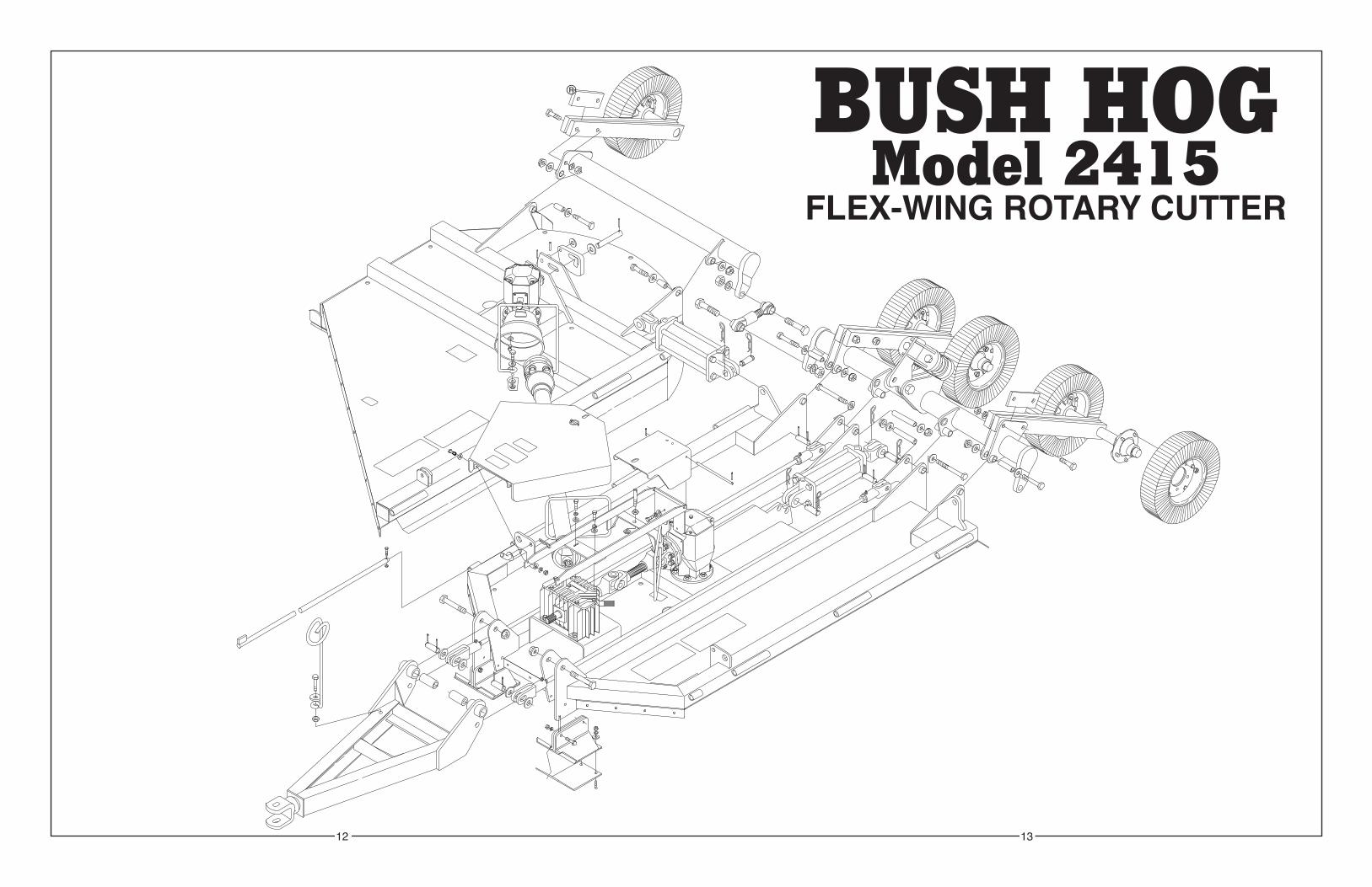
1-2 DESCRIPTIONThe Model 2415 Rotary Cutter (Figure 1-1) consistsof a center unit with two variable position wingstogether having a cutting width of 15 feet (4.5m).Wing operating angles and machine cutting heightare independently controlled using hydraulic cylin-ders. A self-leveling linkage maintains a level cutterat all cutting heights. Power from the tractor PTO issplit at the center gearbox and supplied to each ofthe blade gearboxes. Each blade gearbox has two
free-swinging uplift blades designed for light mow-ing. Free-swinging blades reduce the shock ofimpact when a stationary object is hit. Slip clutchesare installed on each gearbox for additional protec-tion. Front and rear center discharge shields areincluded as standard equipment. (Note: Dealer orpurchaser may elect to delete the front shields attheir option.) Machine specifications are given inTable 1-1.
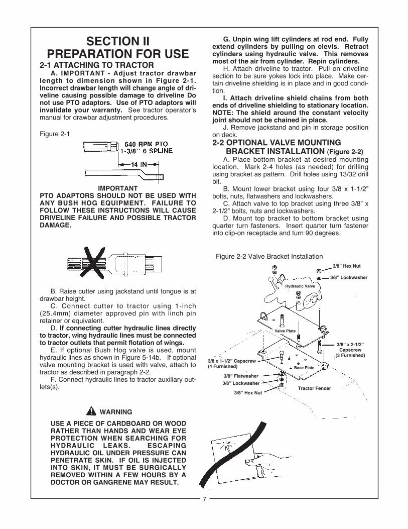
2-1 ATTACHING TO TRACTORA. IMPORTANT - Adjust tractor drawbar
length to dimension shown in Figure 2-1.Incorrect drawbar length will change angle of dri-veline causing possible damage to driveline Donot use PTO adaptors. Use of PTO adaptors willinvalidate your warranty. See tractor operator’smanual for drawbar adjustment procedures.
IMPORTANTPTO ADAPTORS SHOULD NOT BE USED WITHANY BUSH HOG EQUIPMENT. FAILURE TOFOLLOW THESE INSTRUCTIONS WILL CAUSEDRIVELINE FAILURE AND POSSIBLE TRACTORDAMAGE.
B. Raise cutter using jackstand until tongue is atdrawbar height.
C. Connect cutter to tractor using 1-inch(25.4mm) diameter approved pin with linch pinretainer or equivalent.
D. If connecting cutter hydraulic lines directlyto tractor, wing hydraulic lines must be connectedto tractor outlets that permit flotation of wings.
E. If optional Bush Hog valve is used, mounthydraulic lines as shown in Figure 5-14b. If optionalvalve mounting bracket is used with valve, attach totractor as described in paragraph 2-2.
F. Connect hydraulic lines to tractor auxiliary out-lets(s).
USE A PIECE OF CARDBOARD OR WOOD RATHER THAN HANDS AND WEAR EYE PROTECTION WHEN SEARCHING FOR HYDRAULIC LEAKS. ESCAPING HYDRAULIC OIL UNDER PRESSURE CAN PENETRATE SKIN. IF OIL IS INJECTED INTO SKIN, IT MUST BE SURGICALLY REMOVED WITHIN A FEW HOURS BY A DOCTOR OR GANGRENE MAY RESULT.
G. Unpin wing lift cylinders at rod end. Fullyextend cylinders by pulling on clevis. Retractcylinders using hydraulic valve. This removesmost of the air from cylinder. Repin cylinders.
H. Attach driveline to tractor. Pull on drivelinesection to be sure yokes lock into place. Make cer-tain driveline shielding is in place and in good condi-tion.
I. Attach driveline shield chains from bothends of driveline shielding to stationary location.NOTE: The shield around the constant velocityjoint should not be chained in place.
J. Remove jackstand and pin in storage positionon deck.2-2 OPTIONAL VALVE MOUNTING
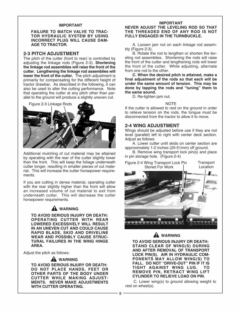
BRACKET INSTALLATION (Figure 2-2)A. Place bottom bracket at desired mounting
location. Mark 2-4 holes (as needed) for drillingusing bracket as pattern. Drill holes using 13/32 drillbit.
B. Mount lower bracket using four 3/8 x 1-1/2”bolts, nuts, flatwashers and lockwashers.
C. Attach valve to top bracket using three 3/8” x2-1/2” bolts, nuts and lockwashers.
D. Mount top bracket to bottom bracket usingquarter turn fasteners. Insert quarter turn fastenerinto clip-on receptacle and turn 90 degrees.
Figure 2-1
Figure 2-2 Valve Bracket Installation3/8” Hex Nut
3/8” Lockwasher
Hydraulic Valve
3/8” x 2-1/2”Capscrew
(3 Furnished)
Tractor Fender
Base Plate
Valve Plate
3/8 x 1-1/2” Capscrew(4 Furnished)
3/8” Flatwasher
3/8” Lockwasher
3/8” Hex Nut
7
WARNING
FAILURE TO MATCH VALVE TO TRAC-TOR HYDRAULIC SYSTEM BY USING INCORRECT PLUG WILL CAUSE DAM-AGE TO TRACTOR.
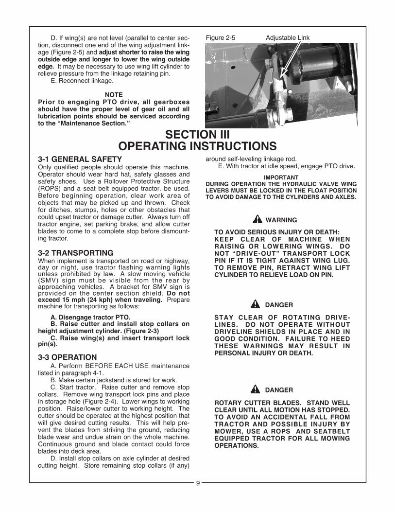
2-3 PITCH ADJUSTMENTThe pitch of the cutter (front to rear) is controlled byadjusting the linkage rods (Figure 2-3). Shorteningthe linkage rod assemblies will raise the front of thecutter. Lengthening the linkage rod assemblies willlower the front of the cutter. The pitch adjustment isprimarily for compensating for the different height oftractor drawbar. As described in the following, it canalso be used to alter the cutting performance. Notethat operating the cutter at any pitch other than par-allel to the ground will produce a slightly uneven cut.
Additional mulching of cut material may be attainedby operating with the rear of the cutter slightly lowerthan the front. This will keep the foliage underneathcutter longer, resulting in smaller pieces of cut mate-rial. This will increase the cutter horsepower require-ments.
If you are cutting in dense material, operating cutterwith the rear slightly higher than the front will allowan increased volume of cut material to exit fromunderneath cutter. This will decrease the cutterhorsepower requirements.
TO AVOID SERIOUS INJURY OR DEATH:OPERATING CUTTER WITH REARLOWERED EXCESSIVELY WILL RESULT IN AN UNEVEN CUT AND COULD CAUSE RAPID BLADE, SKID AND DRIVELINEWEAR AND POSSIBLY CAUSE STRUC-TURAL FAILURES IN THE WING HINGEAREA.
Adjust the pitch as follows:
TO AVOID SERIOUS INJURY OR DEATH:DO NOT PLACE HANDS, FEET OR OTHER PARTS OF THE BODY UNDER CUTTER WHILE MAKING ADJUST-MENTS. NEVER MAKE ADJUSTMENTS WITH CUTTER OPERATING.
IMPORTANT
WARNING
WARNING
IMPORTANTNEVER ADJUST THE LEVELING ROD SO THATTHE THREADED END OF ANY ROD IS NOTFULLY ENGAGED IN THE TURNBUCKLE.
A. Loosen jam nut on each linkage rod assem-bly (Figure 2-3).
B. Rotate the rod to lengthen or shorten the lev-eling rod assemblies. Shortening the rods will raisethe front of the cutter and lengthening rods will lowerthe front of the cutter. While adjusting, alternatefrom one rod to the other.
C. When the desired pitch is attained, make afinal adjustment of the rods so that each will beunder the same amount of tension. This may bedone by tapping the rods and “tuning” them tothe same sound.
D. Re-tighten jam nut.
NOTEIf the cutter is allowed to rest on the ground in orderto relieve tension on the rods, the tongue must bedisconnected from the tractor to allow it to move.
2-4 WING ADJUSTMENTWings should be adjusted before use if they are notlevel (parallel) left to right with center deck section.Adjust as follows:
A. Lower cutter until skids on center section areapproximately 1-2 inches (25-51mm) off ground.
B. Remove wing transport lock pin(s) and placein pin storage hole. (Figure 2-4)
WARNING
TO AVOID SERIOUS INJURY OR DEATH:STAND CLEAR OF WING(S) DURING AND AFTER REMOVAL OF TRANSPORT LOCK PIN(S). AIR IN HYDRAULIC COM-PONENTS MAY ALLOW WING(S) TO FALL. DO NOT “DRIVE-OUT” PIN IF IT IS TIGHT AGAINST WING LUG. TO REMOVE PIN, RETRACT WING LIFT CYLINDER TO RELIEVE LOAD ON PIN.
Figure 2-3 Linkage Rods
Figure 2-4 Wing Transport Lock PinStored For Work
C. Lower wing(s) to ground allowing weight torest on wheel(s).
8
TransportLocation
D. If wing(s) are not level (parallel to center sec-tion, disconnect one end of the wing adjustment link-age (Figure 2-5) and adjust shorter to raise the wingoutside edge and longer to lower the wing outsideedge. It may be necessary to use wing lift cylinder torelieve pressure from the linkage retaining pin.
E. Reconnect linkage.
NOTEPrior to engaging PTO drive, all gearboxesshould have the proper level of gear oil and alllubrication points should be serviced accordingto the “Maintenance Section.”
SECTION IIIOPERATING INSTRUCTIONS
3-1 GENERAL SAFETYOnly qualified people should operate this machine.Operator should wear hard hat, safety glasses andsafety shoes. Use a Rollover Protective Structure(ROPS) and a seat belt equipped tractor. be used.Before beginning operation, clear work area ofobjects that may be picked up and thrown. Checkfor ditches, stumps, holes or other obstacles thatcould upset tractor or damage cutter. Always turn offtractor engine, set parking brake, and allow cutterblades to come to a complete stop before dismount-ing tractor.
3-2 TRANSPORTINGWhen implement is transported on road or highway,day or night, use tractor flashing warning lightsunless prohibited by law. A slow moving vehicle(SMV) sign must be visible from the rear byapproaching vehicles. A bracket for SMV sign isprovided on the center section shield. Do notexceed 15 mph (24 kph) when traveling. Preparemachine for transporting as follows:
A. Disengage tractor PTO.B. Raise cutter and install stop collars on
height adjustment cylinder. (Figure 2-3)C. Raise wing(s) and insert transport lock
pin(s).
3-3 OPERATIONA. Perform BEFORE EACH USE maintenance
listed in paragraph 4-1.B. Make certain jackstand is stored for work.C. Start tractor. Raise cutter and remove stop
collars. Remove wing transport lock pins and placein storage hole (Figure 2-4). Lower wings to workingposition. Raise/lower cutter to working height. Thecutter should be operated at the highest position thatwill give desired cutting results. This will help pre-vent the blades from striking the ground, reducingblade wear and undue strain on the whole machine.Continuous ground and blade contact could forceblades into deck area.
D. Install stop collars on axle cylinder at desiredcutting height. Store remaining stop collars (if any)
around self-leveling linkage rod.E. With tractor at idle speed, engage PTO drive.
IMPORTANTDURING OPERATION THE HYDRAULIC VALVE WINGLEVERS MUST BE LOCKED IN THE FLOAT POSITIONTO AVOID DAMAGE TO THE CYLINDERS AND AXLES.
TO AVOID SERIOUS INJURY OR DEATH:KEEP CLEAR OF MACHINE WHENRAISING OR LOWERING WINGS. DO NOT “DRIVE-OUT” TRANSPORT LOCK PIN IF IT IS TIGHT AGAINST WING LUG. TO REMOVE PIN, RETRACT WING LIFT CYLINDER TO RELIEVE LOAD ON PIN.
STAY CLEAR OF ROTATING DRIVE-LINES. DO NOT OPERATE WITHOUT DRIVELINE SHIELDS IN PLACE AND IN GOOD CONDITION. FAILURE TO HEED THESE WARNINGS MAY RESULT IN PERSONAL INJURY OR DEATH.
ROTARY CUTTER BLADES. STAND WELL CLEAR UNTIL ALL MOTION HAS STOPPED.TO AVOID AN ACCIDENTAL FALL FROM TRACTOR AND POSSIBLE INJURY BY MOWER, USE A ROPS AND SEATBELTEQUIPPED TRACTOR FOR ALL MOWING OPERATIONS.
WARNING
DANGER
DANGER
Figure 2-5 Adjustable Link
9
F. Place tractor in gear and proceed forward.Advance tractor throttle to correct PTO speed forimplement (540 RPM). Tractor forward speedshould be controlled by gear selection, not enginespeed. For maximum cutting efficiency, forwardspeed should allow cutter to maintain a con-stant, maximum blade speed. Failure to maintainproper blade RPM will result in poor cutting perfor-mance and excessive blade and blade bolt wear. IfPTO drive is disengaged due to cutter stalling ortractor engine bogging, cutter must be raised tomaximum cutting height and tractor throttle reducedto idle before re-engaging. When in areas with tall,dense material, the front skids may push materialover and hold it down long enough to prevent bladesfrom cutting it. This will be evidenced by streaking inthe skid area. To alleviate this problem, removethe front skids.
IMPORTANTDURING OPERATION, STOP AT REGULARINTERVALS AND CLEAN ACCUMULATEDDEBRIS FROM THE TOP OF CUTTER DECK,ESPECIALLY AROUND DRIVELINES AND GEAR-BOXES. THIS WILL HELP PREVENT MATERIALFROM CATCHING FIRE.
ALL ROTARY CUTTERS HAVE THE ABILITY TO DISCHARGE OBJECTS AT HIGH SPEEDS WHICH COULD RESULT IN SERIOUS INJURYTO BYSTANDERS OR PASSERS-BY.
THEREFORE, THIS CUTTER IS NOT TO BE OPERATED ALONG HIGHWAYS OR IN ANY AREA WHERE PEOPLE MAY BE PRESENT UNLESS ALL SIDES OF THE UNIT ARE ENCLOSED BY PERMANENT BANDS, SAFE-TY CHAINS, OR OTHER FACTORY APPROVED SAFETY SHIELDS THAT ARE IN GOOD REPAIR.
WARNING
SECTION IVMAINTENANCE
4-1 MAINTENANCE CHECK LISTPerform scheduled maintenance as outlined below.Lower machine to ground, turn off tractor and setparking brake before doing maintenance, inspec-tions, or work. Some checks may require raisingmachine off ground and supporting with blocks. Allbolts should be torqued as recommended in TorqueChart unless otherwise indicated.
THE CUTTER CAN FALL FROM HYDRAULIC SYSTEM FAILURE . TO AVOID SERIOUS INJURY OR DEATH, SECURELY SUPPORT CUTTER BEFORE WORKING UNDERNEATH.
BEFORE EACH USE
1. Make certain driveline shields are in place and ingood repair to minimize entanglement injuries to persons by rotating drivelines. Driveline shields should be chained for non-rotation.
2. Make certain deflector shields (chains, bands,etc.) are in good repair to minimize injuries to person by the discharge of high speed thrown objects.
3. Inspect blades for wear. Replace if necessary per paragraph 4-3. Always replace both blades on spindle with two blades equal inweight. Use only genuine Bush Hog replace-ment blades.
4. Check blade bolts for tightness.Tighten to 450 ft./lbs.
5. Check blades and spindles to be sure that no for-eign objects such as wire or steel strapping bands are wrapped around them.
6. Inspect hydraulic lines and fittings for wear orleaks. Repair or replace if needed.
WARNING
USE A PIECE OF CARDBOARD OR WOOD RATHER THAN HANDS AND WEAR EYE PROTECTION WHEN SEARCHING FORHYDRAULIC LEAKS. ESCAPING HYDRAULIC OIL UNDER PRESSURE CAN PENETRATE THE SKIN. IF OIL IS INJECTED INTO THE SKIN, IT MUST BE SURGICALLY REMOVED WITHIN A FEW HOURS BY A DOCTOR ORGANGRENE MAY RESULT.
7. Inspect wheel(s) for wear, damage or foreignobjects. Repair or replace if necessary.
8. Check tractor tire air pressure. Refer to tractoroperator’s manual.
9. Perform BEFORE EACH USE lubrication perparagraph 4-2.
10. During operation, listen for abnormal sounds which might indicate loose parts, damaged bear-ings or other damage.
11. Check tapered pin retaining each end of each driveline for tightness. Tighten nut to 30 ft./lbs. Use only genuine Bush Hog replacement parts.
AFTER EACH USE
1. Clean all debris from machine and affixed safetydecals. Replace any missing or illegible decals.
2. Inspect cutter for worn or damaged components. Repair or replace before next use. Any replace-ment components installed during repair shall include the components current safety decalsspecified by the manufacturer to be affixed to the component.
3. Store cutter in a dry place.
10
WARNING
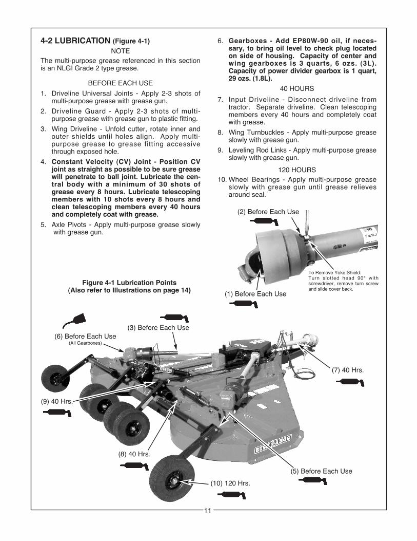
4-2 LUBRICATION (Figure 4-1)NOTE
The multi-purpose grease referenced in this sectionis an NLGI Grade 2 type grease.
BEFORE EACH USE
1. Driveline Universal Joints - Apply 2-3 shots of multi-purpose grease with grease gun.
2. Driveline Guard - Apply 2-3 shots of multi-purpose grease with grease gun to plastic fitting.
3. Wing Driveline - Unfold cutter, rotate inner and outer shields until holes align. Apply multi-purpose grease to grease fitting accessive through exposed hole.
4. Constant Velocity (CV) Joint - Position CV joint as straight as possible to be sure greasewill penetrate to ball joint. Lubricate the cen-tral body with a minimum of 30 shots ofgrease every 8 hours. Lubricate telescopingmembers with 10 shots every 8 hours andclean telescoping members every 40 hoursand completely coat with grease.
Figure 4-1 Lubrication Points(Also refer to Illustrations on page 14)
(2) Before Each Use
(1) Before Each Use
To Remove Yoke Shield:Turn slotted head 90° withscrewdriver, remove turn screwand slide cover back.
11
(9) 40 Hrs.
(5) Before Each Use
6. Gearboxes - Add EP80W-90 oil, if neces-sary, to bring oil level to check plug located on side of housing. Capacity of center and wing gearboxes is 3 quarts, 6 ozs. (3L). Capacity of power divider gearbox is 1 quart,29 ozs. (1.8L).
40 HOURS
7. Input Driveline - Disconnect driveline fromtractor. Separate driveline. Clean telescoping members every 40 hours and completely coat with grease.
slowly with grease gun until grease relieves around seal.
BUSH HOGModel 2415
FLEX-WING ROTARY CUTTER
12 13
®
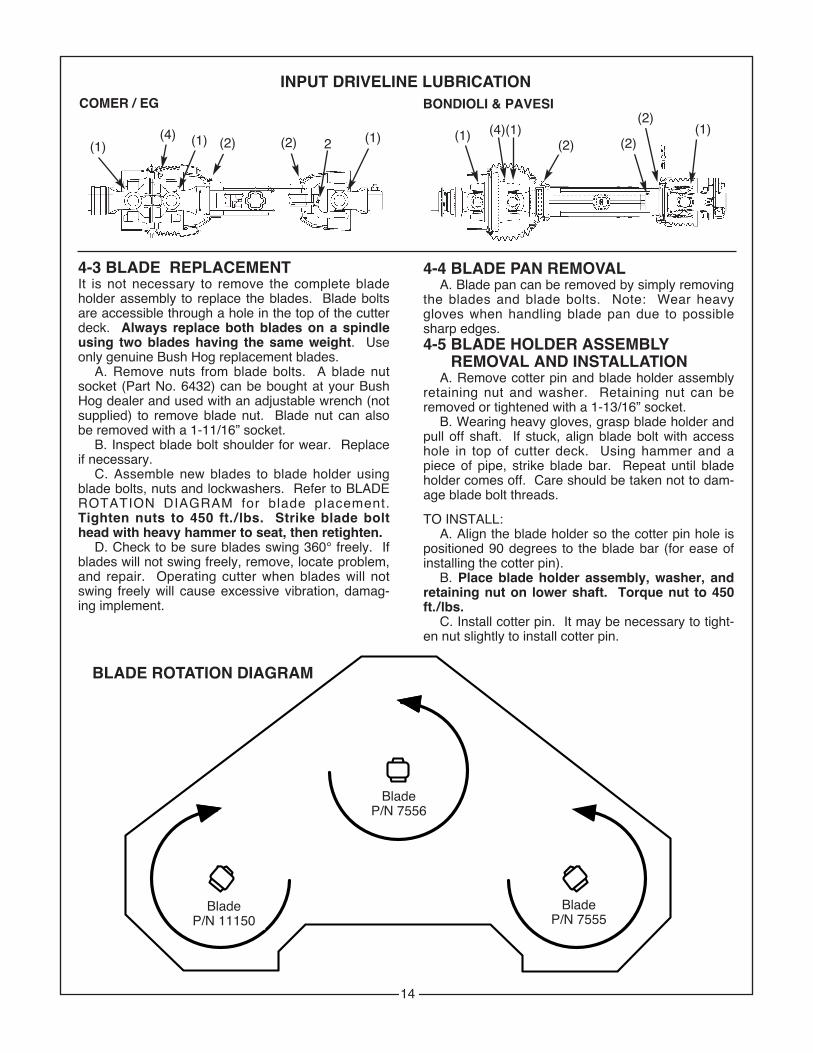
4-3 BLADE REPLACEMENTIt is not necessary to remove the complete bladeholder assembly to replace the blades. Blade boltsare accessible through a hole in the top of the cutterdeck. Always replace both blades on a spindleusing two blades having the same weight. Useonly genuine Bush Hog replacement blades.
A. Remove nuts from blade bolts. A blade nutsocket (Part No. 6432) can be bought at your BushHog dealer and used with an adjustable wrench (notsupplied) to remove blade nut. Blade nut can alsobe removed with a 1-11/16” socket.
B. Inspect blade bolt shoulder for wear. Replaceif necessary.
C. Assemble new blades to blade holder usingblade bolts, nuts and lockwashers. Refer to BLADEROTATION DIAGRAM for blade placement.Tighten nuts to 450 ft. / lbs. Strike blade bolthead with heavy hammer to seat, then retighten.
D. Check to be sure blades swing 360° freely. Ifblades will not swing freely, remove, locate problem,and repair. Operating cutter when blades will notswing freely will cause excessive vibration, damag-ing implement.
4-4 BLADE PAN REMOVALA. Blade pan can be removed by simply removing
the blades and blade bolts. Note: Wear heavygloves when handling blade pan due to possiblesharp edges.4-5 BLADE HOLDER ASSEMBLY
REMOVAL AND INSTALLATIONA. Remove cotter pin and blade holder assembly
retaining nut and washer. Retaining nut can beremoved or tightened with a 1-13/16” socket.
B. Wearing heavy gloves, grasp blade holder andpull off shaft. If stuck, align blade bolt with accesshole in top of cutter deck. Using hammer and apiece of pipe, strike blade bar. Repeat until bladeholder comes off. Care should be taken not to dam-age blade bolt threads.
TO INSTALL:A. Align the blade holder so the cotter pin hole is
positioned 90 degrees to the blade bar (for ease ofinstalling the cotter pin).
B. Place blade holder assembly, washer, andretaining nut on lower shaft. Torque nut to 450ft./lbs.
C. Install cotter pin. It may be necessary to tight-en nut slightly to install cotter pin.
IMPORTANTDO NOT OVER-TIGHTEN NUT AND CAUSESPRING TO BECOME SOLID AS THIS WILLCAUSE SHAFT TO FAIL.
4-8 TROUBLESHOOTINGTroubleshooting procedures are listed in Table 4-1.If the problem cannot be solved or replacement partsare necessary, contact your authorized Bush Hogdealer. Please have ready your machine name,model number, serial number, purchase date andexact cause or description of problem.
TABLE 4-1 GENERAL TROUBLESHOOTINGPROBLEM PROBABLE CAUSE REMEDYUneven cut Cutter not level side to side or front to rear. Refer to Section II.
Worn or bent blades. Replace blades per paragraph 4-3.
Streaking or Windrowing. Possible build-up of material under cutter. Clean cutter.Cutter not level. Refer to SECTION II.Worn blades. Replace per paragraph 4-3.Cutter not being operated at RPM speed. Set tractor throttle for proper PTO
speed during operation.Front skids holding tall material down. Remove front skids.
Noisy cutter. Loose components. Check all bolts for tightness.
Low oil in gearboxes. Check for proper oil level. Refer toparagraph 4-2.
Rapid blade wear. Blade contacting the ground. Adjust cutter to operate at a height(cutting edge) that will eliminate ground contact.
Rapid blade wear. Cutter not being operated at rated Set tractor throttle for proper PTO(bolt hole) RPM speed. speed during operation.
Cutter vibration. Cutter not being operated at rated Set tractor throttle for proper PTORPM speed. speed during operation.Blades on same spindle have unequal wgt. Replace blades with matched set.
Wings wil not raise. Valve plumbed wrong. Plumb as shown in Figure 5-12.Reverse hoses to tractor auxiliaryhydraulics outlets.
Shields failing. Excess debris accumulation. Clean debris from cutter.No grease. Lubricate shields per para. 4-2.Not chained. Fasten shield chain to stationary location.
Figure 4-2 Spring Length
15
After implement has been stored for 30 days ormore, perform the following operational check:
A. Loosen eight nuts retaining clutch springs 1/3turn or until spring can be turned with fingers.
B. With tractor at idle speed, engage tractor PTOdrive for 2-3 seconds. Clutch should slip withoutturning blades. If clutch does not slip, contact yourauthorized Bush Hog dealer.
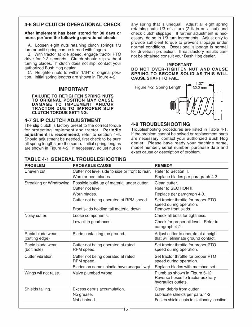
C. Retighten nuts to within 1/64” of original posi-tion. Initial spring lengths are shown in Figure 4-2.
IMPORTANTFAILURE TO RETIGHTEN SPRING NUTS TO ORIGINAL POSITION MAY CAUSE DAMAGE TO IMPLEMENT AND/OR TRACTOR DUE TO IMPROPER SLIP CLUTCH TORQUE SETTING.
4-7 SLIP CLUTCH ADJUSTMENTThe slip clutch is factory preset to the correct torquefor protecting implement and tractor. Periodicadjustment is recommend; refer to section 4-6.Should adjustment be needed, first check to be sureall spring lengths are the same. Initial spring lengthsare shown in Figure 4-2. If necessary, adjust nut on
any spring that is unequal. Adjust all eight springretaining nuts 1/3 of a turn (2 flats on a nut) andcheck clutch slippage. If further adjustment is nec-essary, do so in 1/3 turn increments. Adjust only toprovide sufficient torque to prevent slippage undernormal conditions. Occasional slippage is normalfor drivetrain protection. If satisfactory results can-not be obtained consult your Bush Hog dealer.