PG-1 POWER SUPPLY, GROUND & CIRCUIT ELEMENTS K ELECTRICAL CONTENTS C D E F G H I J L M SECTION A B PG Revision: July 2005 2005 Maxima PRECAUTIONS ......................................................... 3 Precautions for Supplemental Restraint System (SRS) “AIR BAG” and “SEAT BELT PRE-TEN- SIONER” ................................................................. 3 Wiring Diagrams and Trouble Diagnosis ................. 3 POWER SUPPLY ROUTING CIRCUIT ..................... 4 Schematic ............................................................... 4 Wiring Diagram — POWER — ................................ 6 BATTERY POWER SUPPLY — IGNITION SW. IN ANY POSITION ............................................... 6 ACCESSORY POWER SUPPLY — IGNITION SW. IN ACC OR ON ........................................... 10 IGNITION POWER SUPPLY — IGNITION SW. IN ON .................................................................. 11 IGNITION POWER SUPPLY — IGNITION SW. IN ON AND/OR START ...................................... 12 IPDM E/R (INTELLIGENT POWER DISTRIBUTION MODULE ENGINE ROOM) ..................................... 15 System Description ............................................... 15 SYSTEMS CONTROLLED BY IPDM E/R .......... 15 CAN COMMUNICATION LINE CONTROL ........ 15 IPDM E/R STATUS CONTROL .......................... 16 Function of Detecting Ignition Relay Malfunction ... 16 CONSULT-II Function (IPDM E/R) ........................ 17 CONSULT-II BASIC OPERATION ...................... 17 SELF-DIAGNOSTIC RESULTS ......................... 18 DATA MONITOR ................................................ 18 ACTIVE TEST .................................................... 20 Auto Active Test .................................................... 21 DESCRIPTION ................................................... 21 OPERATION PROCEDURE .............................. 21 INSPECTION IN AUTO ACTIVE TEST MODE ... 21 Schematic ............................................................. 23 IPDM E/R Terminal Arrangement .......................... 24 IPDM E/R Power/Ground Circuit Inspection ......... 25 Inspection with CONSULT-II (Self-Diagnosis) ....... 26 Removal and Installation of IPDM E/R .................. 27 REMOVAL .......................................................... 27 INSTALLATION .................................................. 27 GROUND CIRCUIT .................................................. 28 Ground Distribution ................................................ 28 MAIN HARNESS ................................................ 28 ENGINE ROOM HARNESS ............................... 31 ENGINE CONTROL HARNESS ......................... 33 BODY HARNESS ............................................... 34 BODY NO. 2 HARNESS .................................... 35 HARNESS ................................................................ 37 Harness Layout ..................................................... 37 HOW TO READ HARNESS LAYOUT ................ 37 OUTLINE ............................................................ 38 MAIN HARNESS ................................................ 39 ENGINE ROOM HARNESS (LH VIEW) ............. 41 ENGINE ROOM HARNESS (RH VIEW) ............ 44 ENGINE CONTROL HARNESS ......................... 46 BODY HARNESS AND TAIL HARNESS ............ 48 BODY NO. 2 HARNESS AND BODY NO. 3 HAR- NESS .................................................................. 50 ROOM LAMP HARNESS ................................... 52 FRONT DOOR LH HARNESS ........................... 53 FRONT DOOR RH HARNESS ........................... 53 REAR DOOR LH HARNESS .............................. 54 REAR DOOR RH HARNESS ............................. 54 Wiring Diagram Codes (Cell Codes) ..................... 55 ELECTRICAL UNITS LOCATION ........................... 58 Electrical Units Location ........................................ 58 ENGINE COMPARTMENT ................................. 58 PASSENGER COMPARTMENT ........................ 59 Fuse ....................................................................... 61 Fusible Link ........................................................... 61 Circuit Breaker (Built Into BCM) ............................ 61 HARNESS CONNECTOR ........................................ 62 Description ............................................................. 62 HARNESS CONNECTOR (TAB-LOCKING TYPE) ................................................................. 62 HARNESS CONNECTOR (SLIDE-LOCKING TYPE) ................................................................. 63 HARNESS CONNECTOR (DIRECT-CONNECT SRS COMPONENT TYPE) ................................ 63
Transcript
PG-1
POWER SUPPLY, GROUND & CIRCUIT ELEMENTS
K ELECTRICAL
CONTENTS
C
D
E
F
G
H
I
J
L
M
SECTION
A
B
PG
Revision: July 2005 2005 Maxima
PRECAUTIONS .......................................................... 3Precautions for Supplemental Restraint System (SRS) “AIR BAG” and “SEAT BELT PRE-TEN-SIONER” .................................................................. 3Wiring Diagrams and Trouble Diagnosis .................. 3
POWER SUPPLY ROUTING CIRCUIT ...................... 4Schematic ................................................................ 4Wiring Diagram — POWER — ................................. 6
BATTERY POWER SUPPLY — IGNITION SW. IN ANY POSITION ................................................ 6ACCESSORY POWER SUPPLY — IGNITION SW. IN ACC OR ON ............................................ 10IGNITION POWER SUPPLY — IGNITION SW. IN ON ...................................................................11IGNITION POWER SUPPLY — IGNITION SW. IN ON AND/OR START ....................................... 12
IPDM E/R (INTELLIGENT POWER DISTRIBUTION MODULE ENGINE ROOM) ...................................... 15
System Description ................................................ 15SYSTEMS CONTROLLED BY IPDM E/R ........... 15CAN COMMUNICATION LINE CONTROL ......... 15IPDM E/R STATUS CONTROL ........................... 16
Function of Detecting Ignition Relay Malfunction ... 16CONSULT-II Function (IPDM E/R) ......................... 17
Auto Active Test ..................................................... 21DESCRIPTION .................................................... 21OPERATION PROCEDURE ............................... 21INSPECTION IN AUTO ACTIVE TEST MODE ... 21
Schematic .............................................................. 23IPDM E/R Terminal Arrangement ........................... 24IPDM E/R Power/Ground Circuit Inspection .......... 25Inspection with CONSULT-II (Self-Diagnosis) ........ 26Removal and Installation of IPDM E/R ................... 27
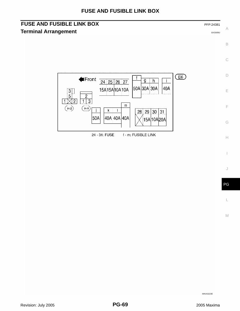
FUSE AND FUSIBLE LINK BOX ..............................69Terminal Arrangement .............................................69
PRECAUTIONS
PG-3
C
D
E
F
G
H
I
J
L
M
A
B
PG
Revision: July 2005 2005 Maxima
PRECAUTIONS PFP:00011
Precautions for Supplemental Restraint System (SRS) “AIR BAG” and “SEAT BELT PRE-TENSIONER” EKS00FSH
The Supplemental Restraint System such as “AIR BAG” and “SEAT BELT PRE-TENSIONER”, used alongwith a front seat belt, helps to reduce the risk or severity of injury to the driver and front passenger for certaintypes of collision. This system includes seat belt switch inputs and dual stage front air bag modules. The SRSsystem uses the seat belt switches to determine the front air bag deployment, and may only deploy one frontair bag, depending on the severity of a collision and whether the front occupants are belted or unbelted.Information necessary to service the system safely is included in the SRS and SB section of this Service Man-ual.WARNING:● To avoid rendering the SRS inoperative, which could increase the risk of personal injury or death
in the event of a collision which would result in air bag inflation, all maintenance must be per-formed by an authorized NISSAN/INFINITI dealer.
● Improper maintenance, including incorrect removal and installation of the SRS, can lead to per-sonal injury caused by unintentional activation of the system. For removal of Spiral Cable and AirBag Module, see the SRS section.
● Do not use electrical test equipment on any circuit related to the SRS unless instructed to in thisService Manual. SRS wiring harnesses can be identified by yellow and/or orange harnesses orharness connectors.
Wiring Diagrams and Trouble Diagnosis EKS00FSI
When you read wiring diagrams, refer to the following:● Refer to GI-13, "How to Read Wiring Diagrams" in GI section. ● Refer to PG-4, "POWER SUPPLY ROUTING CIRCUIT" for power distribution.When you perform trouble diagnosis, refer to the following:● Refer to GI-10, "HOW TO FOLLOW TEST GROUPS IN TROUBLE DIAGNOSES" in GI section.● Refer to GI-25, "How to Perform Efficient Diagnosis for an Electrical Incident" in GI section.
PG-4
POWER SUPPLY ROUTING CIRCUIT
Revision: July 2005 2005 Maxima
POWER SUPPLY ROUTING CIRCUIT PFP:24110
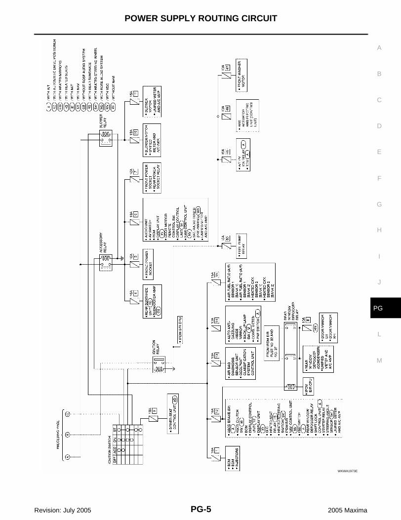
Schematic EKS009HX
For detailed ground distribution, refer to PG-28, "Ground Distribution" .
WKWA1972E
POWER SUPPLY ROUTING CIRCUIT
PG-5
C
D
E
F
G
H
I
J
L
M
A
B
PG
Revision: July 2005 2005 Maxima
WKWA1973E
PG-6
POWER SUPPLY ROUTING CIRCUIT
Revision: July 2005 2005 Maxima
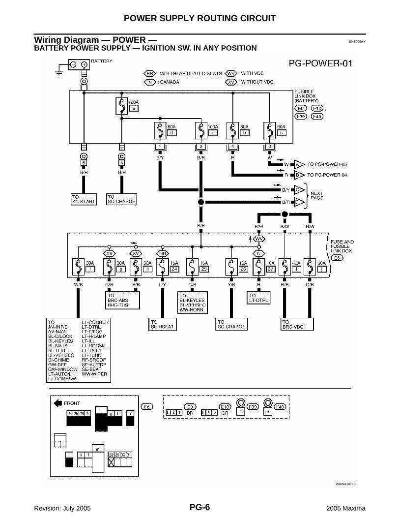
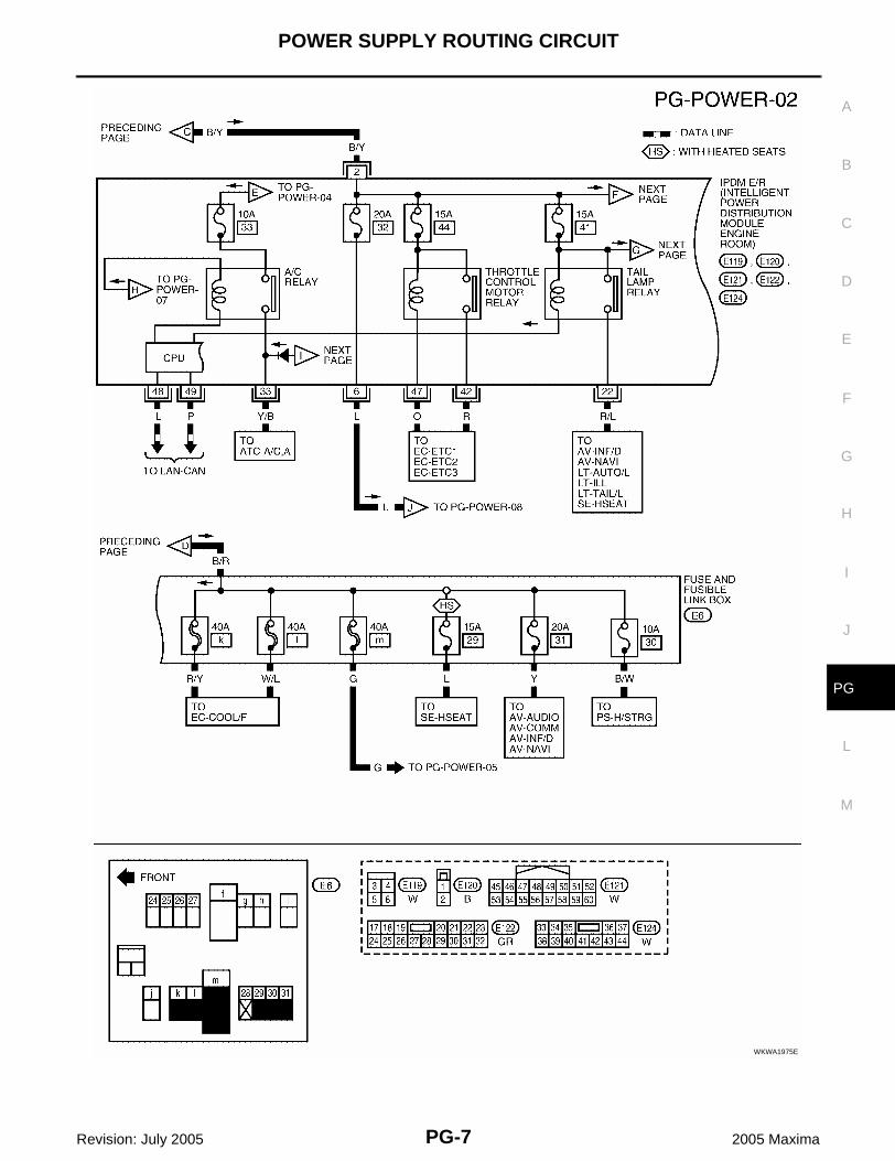
Wiring Diagram — POWER — EKS009HY
BATTERY POWER SUPPLY — IGNITION SW. IN ANY POSITION
WKWA1974E
POWER SUPPLY ROUTING CIRCUIT
PG-7
C
D
E
F
G
H
I
J
L
M
A
B
PG
Revision: July 2005 2005 Maxima
WKWA1975E
PG-8
POWER SUPPLY ROUTING CIRCUIT
Revision: July 2005 2005 Maxima
WKWA3246E
POWER SUPPLY ROUTING CIRCUIT
PG-9
C
D
E
F
G
H
I
J
L
M
A
B
PG
Revision: July 2005 2005 Maxima
WKWA3247E
PG-10
POWER SUPPLY ROUTING CIRCUIT
Revision: July 2005 2005 Maxima
ACCESSORY POWER SUPPLY — IGNITION SW. IN ACC OR ON
WKWA3248E
POWER SUPPLY ROUTING CIRCUIT
PG-11
C
D
E
F
G
H
I
J
L
M
A
B
PG
Revision: July 2005 2005 Maxima
IGNITION POWER SUPPLY — IGNITION SW. IN ON
WKWA3249E
PG-12
POWER SUPPLY ROUTING CIRCUIT
Revision: July 2005 2005 Maxima
IGNITION POWER SUPPLY — IGNITION SW. IN ON AND/OR START
WKWA3250E
POWER SUPPLY ROUTING CIRCUIT
PG-13
C
D
E
F
G
H
I
J
L
M
A
B
PG
Revision: July 2005 2005 Maxima
WKWA3251E
PG-14
POWER SUPPLY ROUTING CIRCUIT
Revision: July 2005 2005 Maxima
WKWA3252E
IPDM E/R (INTELLIGENT POWER DISTRIBUTION MODULE ENGINE ROOM)
PG-15
C
D
E
F
G
H
I
J
L
M
A
B
PG
Revision: July 2005 2005 Maxima
IPDM E/R (INTELLIGENT POWER DISTRIBUTION MODULE ENGINE ROOM)PFP:284B7
System Description EKS009HZ
● IPDM E/R (Intelligent Power Distribution Module Engine Room) integrates the relay box and fuse blockwhich were originally placed in engine compartment. It controls integrated relays via IPDM E/R control cir-cuit.
● IPDM E/R-integrated control circuit performs ON-OFF operation of relays, CAN communication control, oilpressure switch signal reception, etc.
● It controls operation of each electrical component via BCM and CAN communication lines.CAUTION:None of the IPDM E/R-integrated relays can be removed.
SYSTEMS CONTROLLED BY IPDM E/R1. Lamp control
Using CAN communication lines, it receives signal from BCM and controls the following lamps:● Head lamps (Hi, Lo)● Parking lamps● Tail lamps● Cornering lamps● Front fog lamps
2. Wiper controlUsing CAN communication lines, it receives signals from BCM and controls the front wipers.
3. Rear window defogger relay controlUsing CAN communication lines, it receives signals from BCM and controls the rear window defoggerrelay.
4. A/C compressor controlUsing CAN communication lines, it receives signals from ECM and controls the A/C compressor (mag-netic clutch).
5. Cooling fan controlUsing CAN communication lines, it receives signals from ECM and controls cooling fan.
6. Horn controlUsing CAN communication lines, it receives signals from BCM and controls horn relay.
CAN COMMUNICATION LINE CONTROLWith CAN communication, by connecting each control unit using two communication lines (CAN L-line, CANH-line), it is possible to transmit a maximum amount of information with minimum wiring. Each control unit cantransmit and receive data, and reads necessary information only.1. Fail-safe control
● When CAN communication with other control units is impossible, IPDM E/R performs fail-safe control.After CAN communication returns to normal operation, it also returns to normal control.
● Operation of control parts by IPDM E/R during fail-safe mode is as follows:
Controlled system Fail-safe mode
Headlamp● With the ignition switch ON, the headlamp (low) is ON.
● With the ignition switch OFF, the headlamp (low) is OFF.
Tail and parking lamps ● With the ignition switch ON, the tail and parking lamps are ON.
● With the ignition switch OFF, the tail and parking lamps are OFF.
Cooling fan● With the ignition switch ON, the cooling fan HI operates.
● With the ignition switch OFF, the cooling fan stops.
Front wiperUntil the ignition switch is turned off, the front wiper LO and HI remains in the same status it was in just before fail−safe control was initiated.
Rear window defogger Rear window defogger relay OFF
A/C compressor A/C compressor OFF
Front fog lamps Front fog lamp relay OFF
PG-16
IPDM E/R (INTELLIGENT POWER DISTRIBUTION MODULE ENGINE ROOM)
Revision: July 2005 2005 Maxima
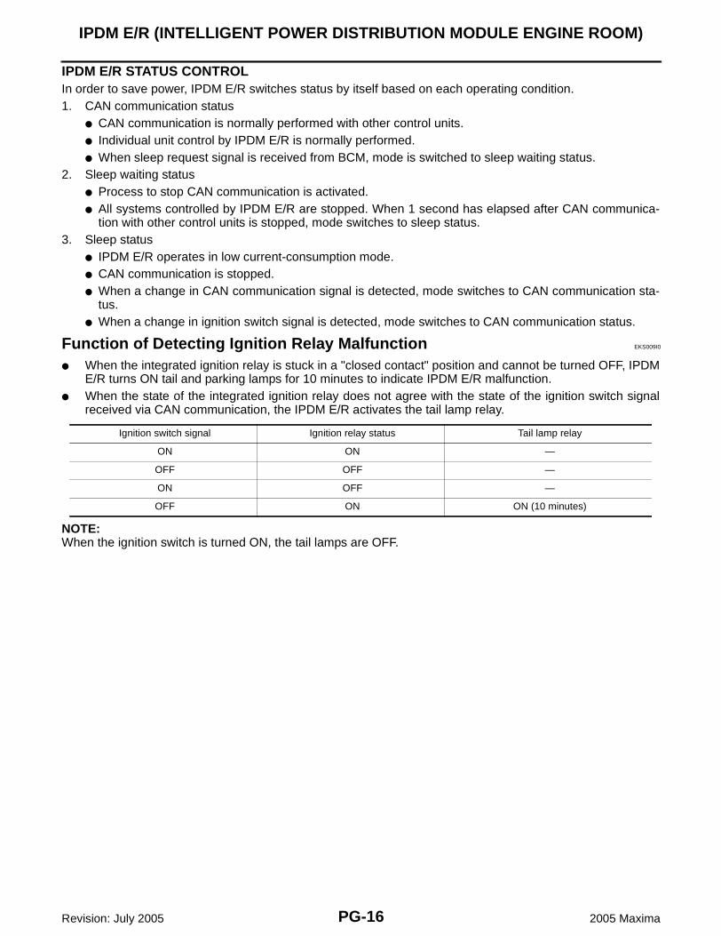
IPDM E/R STATUS CONTROLIn order to save power, IPDM E/R switches status by itself based on each operating condition.1. CAN communication status
● CAN communication is normally performed with other control units.● Individual unit control by IPDM E/R is normally performed.● When sleep request signal is received from BCM, mode is switched to sleep waiting status.
2. Sleep waiting status● Process to stop CAN communication is activated.● All systems controlled by IPDM E/R are stopped. When 1 second has elapsed after CAN communica-
tion with other control units is stopped, mode switches to sleep status.3. Sleep status
● IPDM E/R operates in low current-consumption mode.● CAN communication is stopped.● When a change in CAN communication signal is detected, mode switches to CAN communication sta-
tus.● When a change in ignition switch signal is detected, mode switches to CAN communication status.
Function of Detecting Ignition Relay Malfunction EKS009I0
● When the integrated ignition relay is stuck in a "closed contact" position and cannot be turned OFF, IPDME/R turns ON tail and parking lamps for 10 minutes to indicate IPDM E/R malfunction.
● When the state of the integrated ignition relay does not agree with the state of the ignition switch signalreceived via CAN communication, the IPDM E/R activates the tail lamp relay.
NOTE:When the ignition switch is turned ON, the tail lamps are OFF.
Ignition switch signal Ignition relay status Tail lamp relay
ON ON —
OFF OFF —
ON OFF —
OFF ON ON (10 minutes)
IPDM E/R (INTELLIGENT POWER DISTRIBUTION MODULE ENGINE ROOM)
PG-17
C
D
E
F
G
H
I
J
L
M
A
B
PG
Revision: July 2005 2005 Maxima
CONSULT-II Function (IPDM E/R) EKS009I1
CONSULT-II can display each diagnostic item using the diagnostic test modes shown following.
CONSULT-II BASIC OPERATIONCAUTION:If CONSULT-II is used with no connection of CONSULT-II CONVERTER, malfunctions might bedetected in self-diagnosis depending on control unit which carries out CAN communication.1. With the ignition switch OFF, connect CONSULT-II and CON-
SULT-II CONVERTER to the data link connector, then turn igni-tion switch ON.
2. Touch “START (NISSAN BASED VHCL)”.
3. Touch “IPDM E/R” on “SELECT SYSTEM” screen.● If “IPDM E/R” is not displayed, print "SELECT SYSTEM"
screen, then refer to GI-37, "CONSULT-II Data Link Connec-tor (DLC) Circuit" .
DATA MONITOR Displays IPDM E/R input/output data in real time.
CAN DIAG SUPPORT MNTR The result of transmit/receive diagnosis of CAN communication can be read.
ACTIVE TEST Operation of electrical loads can be checked by sending drive signal to them.
BBIA0002E
BCIA0029E
BCIA0030E
PG-18
IPDM E/R (INTELLIGENT POWER DISTRIBUTION MODULE ENGINE ROOM)
Revision: July 2005 2005 Maxima
4. Select the desired part to be diagnosed on the “SELECT DIAGMODE” screen.
SELF-DIAGNOSTIC RESULTSOperation Procedure1. Touch “SELF-DIAG RESULTS” on “SELECT DIAG MODE”
screen.2. Self-diagnosis results are displayed.
Display Item List
NOTE:The details for display of the period are as follows:● CRNT: Error currently detected with IPDM E/R.● PAST: Error detected in the past and placed in IPDM E/R memory.
DATA MONITOROperation Procedure1. Touch “DATA MONITOR” on “SELECT DIAG MODE” screen.2. Touch "ALL SIGNALS”, “MAIN SIGNALS” or “SELECTION FROM MENU” on the “DATA MONITOR”
screen.
3. Touch “START”.4. Touch the required monitoring item on "SELECTION FROM MENU".
BCIA0031E
SKIA4956E
Display itemsCONSULT-II display code
Error return conditionTIME Possible
causesCRNT PAST
NO DTC IS DETECTED. FURTHER TESTING MAY BE REQUIRED.
— — — — —
CAN COMM CIRC U1000
● If CAN communication reception/transmission data has an error, or if any of the control units fail, data reception/transmission cannot be confirmed.
● When the data in CAN communication is not received before the specified time.
X X
Any of items listed below have errors:
● TRANSMIT DIAG
● ECM
● BCM/SEC
ALL SIGNALS All signals will be monitored.
MAIN SIGNALS Monitors the predetermined item(s).
SELECTION FROM MENU
Selects and monitors individual signal(s).
IPDM E/R (INTELLIGENT POWER DISTRIBUTION MODULE ENGINE ROOM)
PG-19
C
D
E
F
G
H
I
J
L
M
A
B
PG
Revision: July 2005 2005 Maxima
5. Touch “RECORD” while monitoring to record the status of the item being monitored. To stop recording,touch “STOP”.
PG-20
IPDM E/R (INTELLIGENT POWER DISTRIBUTION MODULE ENGINE ROOM)
Revision: July 2005 2005 Maxima
All Signals, Main Signals, Selection From Menu
NOTE:Perform monitoring of IPDM E/R data with the ignition switch ON. When the ignition switch is in ACC position,display may not be correct.
ACTIVE TESTOperation Procedure1. Touch “ACTIVE TEST” on “SELECT DIAG-MODE” screen.2. Touch item to be tested, and check operation.3. Touch “START”.4. Touch "STOP" while testing to stop the operation.
Item nameCONSULT-II
screen display Display or unit
Monitor item selection
DescriptionALLSIGNALS
MAIN SIGNALS
SELECTION FROM MENU
Motor fan request MOTOR FAN REQ 1/2/3/4 X X XSignal status input from ECM
Compressor request
AC COMP REQ ON/OFF X X XSignal status input from ECM
Position lights request
TAIL & CLR REQ ON/OFF X X XSignal status input from BCM
Headlamp LO request
HL LO REQ ON/OFF X X XSignal status input from BCM
Headlamp HI request
HL HI REQ ON/OFF X X XSignal status input from BCM
Front fog lights request
FR FOG REQ ON/OFF X X XSignal status input from BCM
FR wiper request FR WIP REQ STOP/1LO/LO/HI X X XSignal status input from BCM
Wiper auto stop WIP AUTO STOP ACT P/STOP P X X X Output status of IPDM E/R
Wiper protection WIP PROT OFF/LS/HS/Block X X Control status of IPDM E/R
Starter request ST RLY REQ ON/OFF X X Status of input signal NOTE
Ignition relaystatus
IGN RLY ON/OFF X X XIgnition relay status moni-tored with IPDM E/R
Rear defogger request
RR DEF REQ ON/OFF X X XSignal status input from BCM
Oil pressure switch OIL P SW OPEN/CLOSE X XSignal status input from IPDM E/R
Theft warning horn request
THFT HRN REQ ON/OFF X XSignal status input from BCM
Horn chirp HORN CHIRP ON/OFF X X Output status of IPDM E/R
Cornering lamp request
CRNRNG LMP REQ
OFF/LEFT/RIGHT X XSignal status input from BCM
Test name CONSULT-II screen display Description
Tail lamp output TAIL LAMP With a certain ON-OFF operation, the tail lamp relay can be operated.
Rear defogger output REAR DEFOGGERWith a certain ON-OFF operation, the rear defogger relay can be oper-ated.
Front wiper (HI, LO) output FRONT WIPERWith a certain operation (OFF, HI ON, LO ON), the front wiper relay (Lo, Hi) can be operated.
Cooling fan output MOTOR FAN With a certain operation (1, 2, 3, 4), the cooling fan can be operated.
Lamp (HI, LO, FOG) output LAMPSWith a certain operation (OFF, HI ON, LO ON, FOG ON), the lamp relay (Lo, Hi, Fog) can be operated.
IPDM E/R (INTELLIGENT POWER DISTRIBUTION MODULE ENGINE ROOM)
PG-21
C
D
E
F
G
H
I
J
L
M
A
B
PG
Revision: July 2005 2005 Maxima
Auto Active Test EKS009I2
DESCRIPTION● In auto active test mode, operation inspection can be performed when IPDM E/R sends a drive signal to
the following systems:– Rear window defogger– Front wipers– Tail and parking lamps– Cornering lamps– Front fog lamps– Headlamps (Hi, Lo)– A/C compressor (magnetic clutch)– Cooling fan
OPERATION PROCEDURE1. Close hood and front door RH, and lift wiper arms away from windshield (to prevent glass damage by
wiper operation).NOTE:When auto active test is performed with hood opened, sprinkle water on windshield beforehand.
2. Turn ignition switch OFF.3. Turn ignition switch ON and, within 20 seconds, press front door switch LH 10 times. Then turn ignition
switch OFF.4. Turn ignition switch ON within 10 seconds after ignition switch OFF. 5. When auto active test mode is actuated, horn chirps once.6. After a series of operations is repeated three times, auto active test is completed.
NOTE:When auto active test mode has to be cancelled halfway, turn ignition switch OFF.CAUTION:Be sure to perform BL-29, "Door Switch Check" when the auto active test cannot be performed.
INSPECTION IN AUTO ACTIVE TEST MODE● When auto active test mode is actuated, the following nine steps are repeated three times.
Cornering lamp output CORNERING LAMP With a certain operation (OFF, ON), the cornering lamp relay (RH, LH) can be operated.
Horn output HORN With a certain ON-OFF operation, the horn relay can be operated.
Test name CONSULT-II screen display Description
LKIA0317E
PG-22
IPDM E/R (INTELLIGENT POWER DISTRIBUTION MODULE ENGINE ROOM)
Revision: July 2005 2005 Maxima
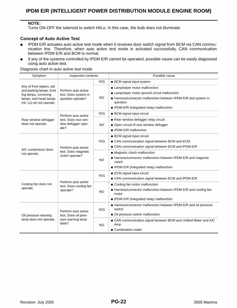
NOTE:Turns ON-OFF the solenoid to switch Hi/Lo. In this case, the bulb does not illuminate.
Concept of Auto Active Test● IPDM E/R actuates auto active test mode when it receives door switch signal from BCM via CAN commu-
nication line. Therefore, when auto active test mode is activated successfully, CAN communicationbetween IPDM E/R and BCM is normal.
● If any of the systems controlled by IPDM E/R cannot be operated, possible cause can be easily diagnosedusing auto active test.
Diagnosis chart in auto active test mode
Symptom Inspection contents Possible cause
Any of front wipers, tail and parking lamps, front fog lamps, cornering lamps, and head lamps (Hi, Lo) do not operate.
Perform auto active test. Does system in question operate?
YES ● BCM signal input system
NO
● Lamp/wiper motor malfunction
● Lamp/wiper motor ground circuit malfunction
● Harness/connector malfunction between IPDM E/R and system in question
● IPDM E/R (integrated relay) malfunction
Rear window defogger does not operate.
Perform auto active test. Does rear win-dow defogger oper-ate?
YES ● BCM signal input circuit
NO
● Rear window defogger relay circuit
● Open circuit of rear window defogger
● IPDM E/R malfunction
A/C compressor does not operate.
Perform auto active test. Does magnetic clutch operate?
YES
● BCM signal input circuit
● CAN communication signal between BCM and ECM.
● CAN communication signal between ECM and IPDM E/R
NO
● Magnetic clutch malfunction
● Harness/connector malfunction between IPDM E/R and magnetic clutch
● IPDM E/R (integrated relay) malfunction
Cooling fan does not operate.
Perform auto active test. Does cooling fan operate?
YES● ECM signal input circuit
● CAN communication signal between ECM and IPDM E/R
NO
● Cooling fan motor malfunction
● Harness/connector malfunction between IPDM E/R and cooling fan motor
● IPDM E/R (integrated relay) malfunction
Oil pressure warning lamp does not operate.
Perform auto active test. Does oil pres-sure warning lamp blink?
YES● Harness/connector malfunction between IPDM E/R and oil pressure
switch
● Oil pressure switch malfunction
NO● CAN communication signal between BCM and Unified Meter and A/C
Amp
● Combination meter
IPDM E/R (INTELLIGENT POWER DISTRIBUTION MODULE ENGINE ROOM)
PG-23
C
D
E
F
G
H
I
J
L
M
A
B
PG
Revision: July 2005 2005 Maxima
Schematic EKS009I3
WKWA2066E
PG-24
IPDM E/R (INTELLIGENT POWER DISTRIBUTION MODULE ENGINE ROOM)
Revision: July 2005 2005 Maxima
IPDM E/R Terminal Arrangement EKS009I4
LKWA0247E
IPDM E/R (INTELLIGENT POWER DISTRIBUTION MODULE ENGINE ROOM)
PG-25
C
D
E
F
G
H
I
J
L
M
A
B
PG
Revision: July 2005 2005 Maxima
IPDM E/R Power/Ground Circuit Inspection EKS009I5
1. FUSE AND FUSIBLE LINK INSPECTION
Check that the following fusible links or IPDM E/R fuses are not blown.
OK or NGOK >> GO TO 2.NG >> Replace fuse or fusible link.
2. POWER CIRCUIT INSPECTION
1. Disconnect IPDM E/R harness connector E120.2. Check voltage between IPDM E/R harness connector E120 terminals 1 (R), 2 (B/Y) and ground.
OK or NGOK >> GO TO 3.NG >> Repair or replace IPDM E/R power circuit harness.
3. GROUND CIRCUIT INSPECTION
1. Disconnect IPDM E/R harness connectors E121 and E124.2. Check continuity between IPDM E/R harness connector (A)
OK or NGOK >> Inspection End.NG >> Repair or replace ground circuit harness of IPDM E/R.
Terminal No. Signal name Fuse, fusible link No.
1, 2 Battery power a, b, d
Battery voltage should exist
SKIA1987E
Continuity should exist
WKIA4257E
PG-26
IPDM E/R (INTELLIGENT POWER DISTRIBUTION MODULE ENGINE ROOM)
Revision: July 2005 2005 Maxima
Inspection with CONSULT-II (Self-Diagnosis) EKS009I6
CAUTION:If a CONSULT-II is used with no connection of CONSULT-II CONVERTER, malfunctions might bedetected in self-diagnosis depending on which control unit(s) carry out CAN communication.
1. SELF-DIAGNOSIS RESULT CHECK
1. Connect CONSULT-II and select "IPDM E/R" on the Diagnosis System Selection screen.2. Select "SELF-DIAG RESULTS" on the diagnosis mode selection screen.3. Check display content in self-diagnosis results.
NOTE:The Details for Display for the Period are as follows:● CRNT: Error currently detected by IPDM E/R.● PAST: Error detected in the past and stored in IPDM E/R memory.Contents displayedNO DTC DETECTED. FURTHER TESTING MAY BE REQUIRED.>>INSPECTION END.CAN COMM CIRC>>Print out the self diagnosis results and refer to LAN-7, "CAN COMMUNICATION" .
CONSULT-II DisplayCONSULT-II display code
TIMEDetails of diagnosis result
CRNT PAST
NO DTC IS DETECTED.FURTHER TESTING MAY BE REQUIRED.
— — — No malfunction
CAN COMM CIRC U1000 X X
Any of items listed below have errors:
● TRANSMIT DIAG
● ECM
● BCM/SEC
IPDM E/R (INTELLIGENT POWER DISTRIBUTION MODULE ENGINE ROOM)
PG-27
C
D
E
F
G
H
I
J
L
M
A
B
PG
Revision: July 2005 2005 Maxima
Removal and Installation of IPDM E/R EKS009I7
REMOVAL1. Disconnect negative battery cable.2. Remove engine side cover RH. 3. Remove 2 bolts and position coolant reservoir aside. 4. Remove IPDM E/R upper cover.
5. Remove IPDM E/R harness cover.
6. Release 2 clips and pull IPDM E/R up from case.7. Disconnect IPDM E/R connectors and remove the IPDM E/R.
INSTALLATIONInstallation is in the reverse order of removal.
WKIA0120E
WKIA0121E
WKIA0122E
PG-28
GROUND CIRCUIT
Revision: July 2005 2005 Maxima
GROUND CIRCUIT PFP:24080
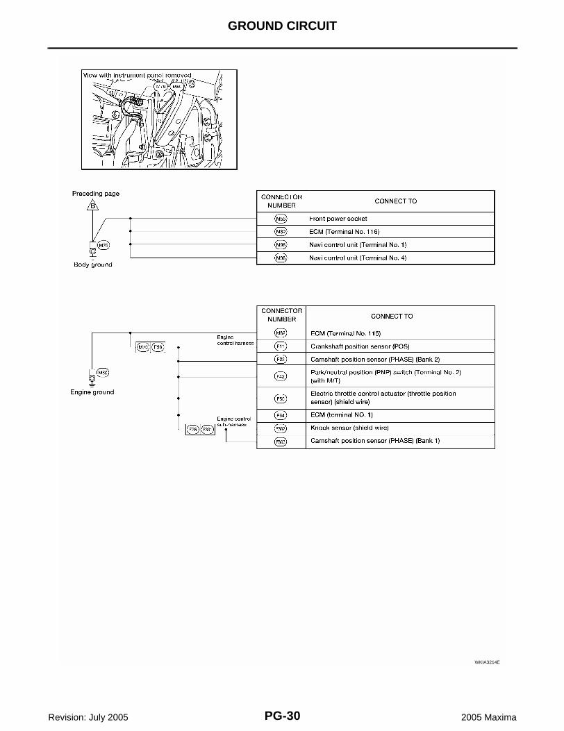
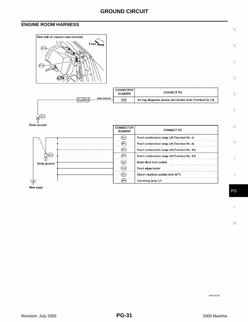
Ground Distribution EKS009I8
MAIN HARNESS
WKIA3211E
GROUND CIRCUIT
PG-29
C
D
E
F
G
H
I
J
L
M
A
B
PG
Revision: July 2005 2005 Maxima
WKIA3212E
PG-30
GROUND CIRCUIT
Revision: July 2005 2005 Maxima
WKIA3214E
GROUND CIRCUIT
PG-31
C
D
E
F
G
H
I
J
L
M
A
B
PG
Revision: July 2005 2005 Maxima
ENGINE ROOM HARNESS
WKIA3213E
PG-32
GROUND CIRCUIT
Revision: July 2005 2005 Maxima
WKIA3215E
GROUND CIRCUIT
PG-33
C
D
E
F
G
H
I
J
L
M
A
B
PG
Revision: July 2005 2005 Maxima
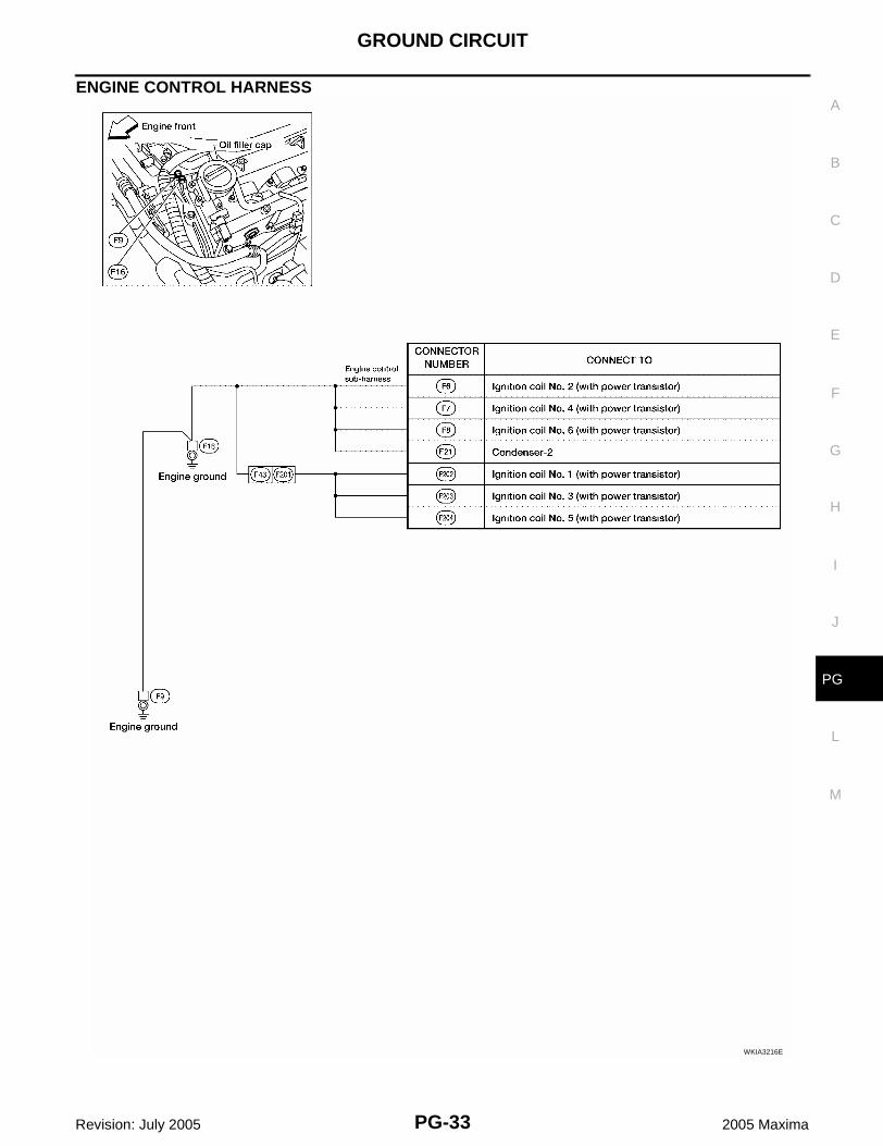
ENGINE CONTROL HARNESS
WKIA3216E
PG-34
GROUND CIRCUIT
Revision: July 2005 2005 Maxima
BODY HARNESS
WKIA3217E
GROUND CIRCUIT
PG-35
C
D
E
F
G
H
I
J
L
M
A
B
PG
Revision: July 2005 2005 Maxima
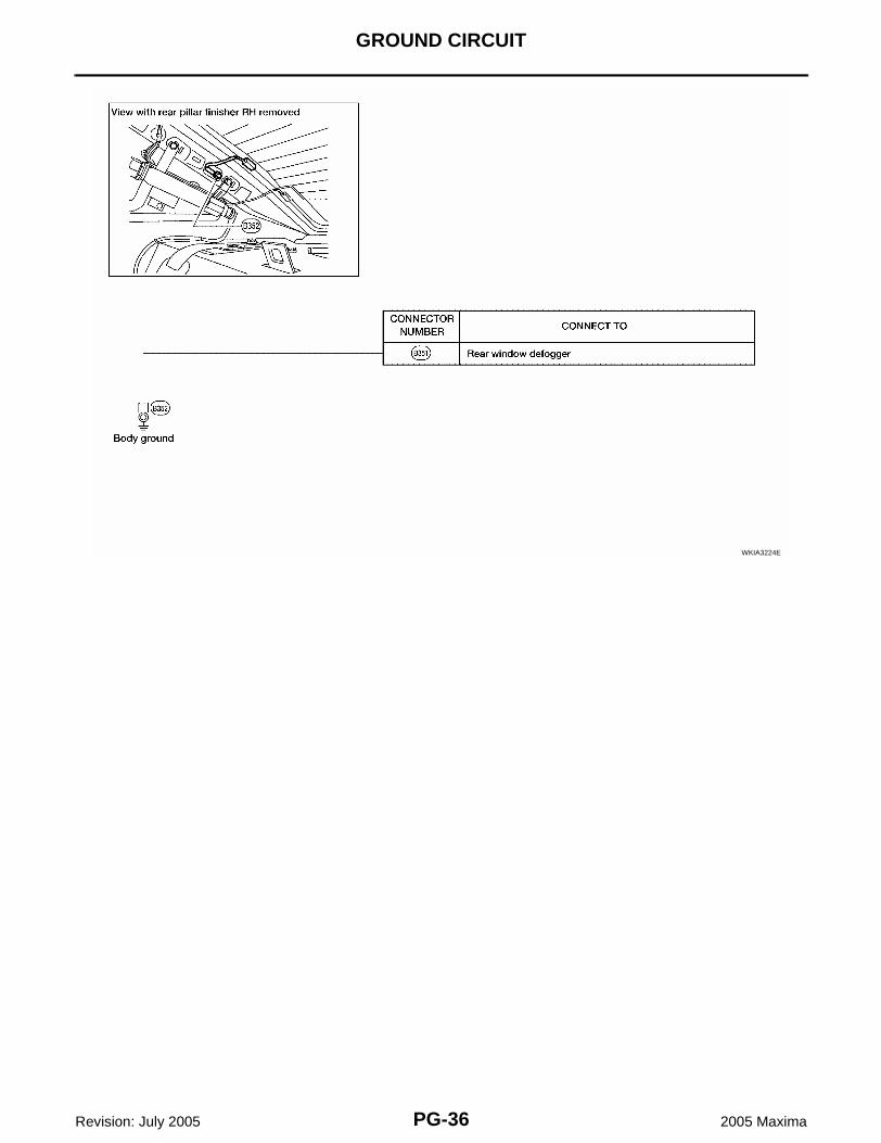
BODY NO. 2 HARNESS
WKIA3218E
PG-36
GROUND CIRCUIT
Revision: July 2005 2005 Maxima
WKIA3224E
HARNESS
PG-37
C
D
E
F
G
H
I
J
L
M
A
B
PG
Revision: July 2005 2005 Maxima
HARNESS PFP:24010
Harness Layout EKS009I9
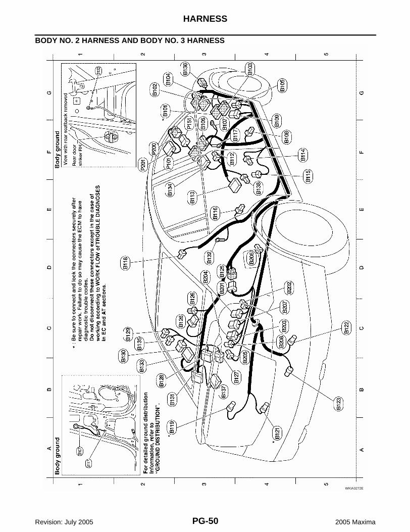
HOW TO READ HARNESS LAYOUT The following Harness Layouts use a map style grid to help locateconnectors on the drawings:● Main Harness● Engine Room Harness LH View (Engine Compartment)● Engine Room Harness RH View (Engine Compartment)● Engine Control Harness● Body Harness and Tail Harness● Body No. 2 Harness and Body No. 3 HarnessTo use the grid reference1. Find the desired connector number on the connector list.2. Find the grid reference.3. On the drawing, find the crossing of the grid reference letter column and number row.4. Find the connector number in the crossing zone.5. Follow the line (if used) to the connector.
CONNECTOR SYMBOLMain symbols of connector (in Harness Layout) are indicated below.
SEL252V
Connector typeWater proof type Standard type
Male Female Male Female
● Cavity: 4 or Less
● Relay connector
● Cavity: From 5 to 8
● Cavity: 9 or More
● Ground terminal etc. —
PG-38
HARNESS
Revision: July 2005 2005 Maxima
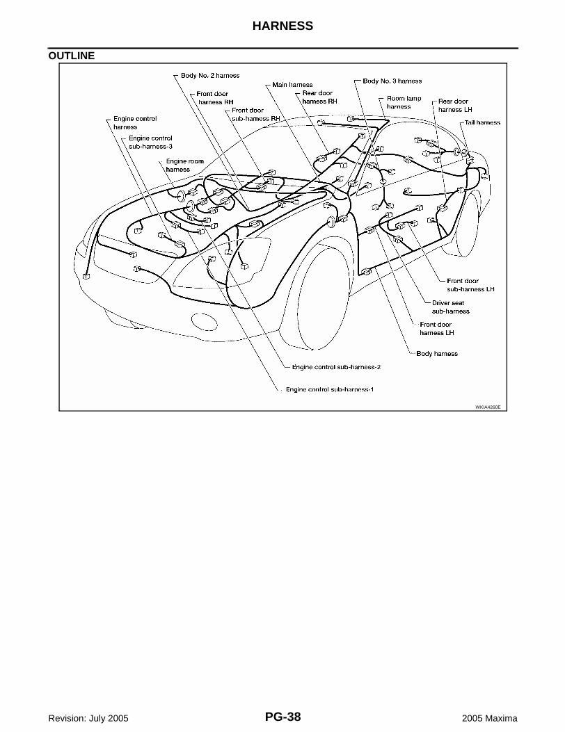
OUTLINE
WKIA4260E
HARNESS
PG-39
C
D
E
F
G
H
I
J
L
M
A
B
PG
Revision: July 2005 2005 Maxima
MAIN HARNESS
WKIA3262E
PG-40
HARNESS
Revision: July 2005 2005 Maxima
WKIA3263E
HARNESS
PG-41
C
D
E
F
G
H
I
J
L
M
A
B
PG
Revision: July 2005 2005 Maxima
ENGINE ROOM HARNESS (LH VIEW)Engine Compartment
Refer to PG-44, "ENGINE ROOM HARNESS (RH VIEW)" for continuation of engine room harness.WKIA3264E
PG-42
HARNESS
Revision: July 2005 2005 Maxima
WKIA3265E
HARNESS
PG-43
C
D
E
F
G
H
I
J
L
M
A
B
PG
Revision: July 2005 2005 Maxima
Passenger Compartment
WKIA3266E
PG-44
HARNESS
Revision: July 2005 2005 Maxima
ENGINE ROOM HARNESS (RH VIEW)Engine Compartment
Refer to PG-41, "ENGINE ROOM HARNESS (LH VIEW)" for continuation of engine room harness.WKIA0503E
HARNESS
PG-45
C
D
E
F
G
H
I
J
L
M
A
B
PG
Revision: July 2005 2005 Maxima
WKIA3267E
PG-46
HARNESS
Revision: July 2005 2005 Maxima
ENGINE CONTROL HARNESS
WKIA3268E
HARNESS
PG-47
C
D
E
F
G
H
I
J
L
M
A
B
PG
Revision: July 2005 2005 Maxima
WKIA4258E
PG-48
HARNESS
Revision: July 2005 2005 Maxima
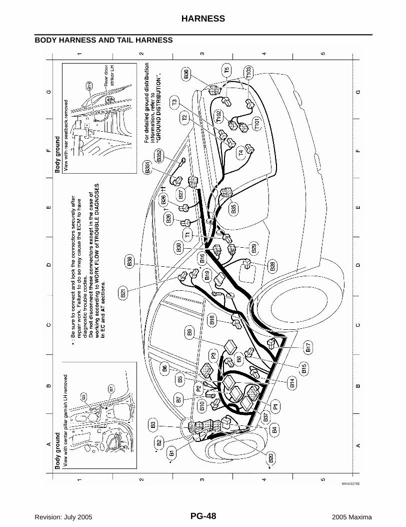
BODY HARNESS AND TAIL HARNESS
WKIA3270E
HARNESS
PG-49
C
D
E
F
G
H
I
J
L
M
A
B
PG
Revision: July 2005 2005 Maxima
WKIA4259E
PG-50
HARNESS
Revision: July 2005 2005 Maxima
BODY NO. 2 HARNESS AND BODY NO. 3 HARNESS
WKIA3272E
HARNESS
PG-51
C
D
E
F
G
H
I
J
L
M
A
B
PG
Revision: July 2005 2005 Maxima
WKIA3273E
PG-52
HARNESS
Revision: July 2005 2005 Maxima
ROOM LAMP HARNESS
WKIA3274E
HARNESS
PG-53
C
D
E
F
G
H
I
J
L
M
A
B
PG
Revision: July 2005 2005 Maxima
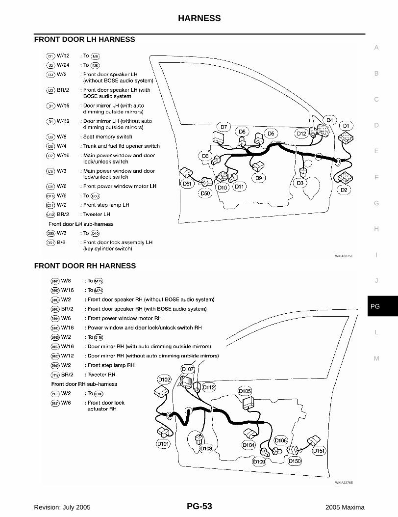
FRONT DOOR LH HARNESS
FRONT DOOR RH HARNESSWKIA3275E
WKIA3276E
PG-54
HARNESS
Revision: July 2005 2005 Maxima
REAR DOOR LH HARNESS
REAR DOOR RH HARNESSWKIA3277E
WKIA0515E
HARNESS
PG-55
C
D
E
F
G
H
I
J
L
M
A
B
PG
Revision: July 2005 2005 Maxima
Wiring Diagram Codes (Cell Codes) EKS009IA
Use the chart below to find out what each wiring diagram code stands for.Refer to the wiring diagram code in the alphabetical index to find the location (page number) of each wiringdiagram.
PGC/V EC EVAP Canister Purge Volume Control Solenoid Valve
PHSB1 EC Camshaft Position Sensor (PHASE) (Bank 1)
PHSB2 EC Camshaft Position Sensor (PHASE) (Bank 2)
PNP/SW AT Park/Neutral Position Switch
PNP/SW EC Park/Neutral Position Switch
POS EC Crankshaft Position Sensor (CKPS) (POS)
POWER PG Power Supply Routing
PRE/SE EC EVAP Control System Pressure Sensor
P/SCKT WW Power Socket
PS/SEN EC Power Steering Oil Pressure Sensor
PWR/IN AT TCM Ignition Power
ROOM/L LT Interior Room Lamp
RP/SEN EC Refrigerant Pressure Sensor
S/SIG EC Start Signal
SEAT SE Power Seat
SEN/PW EC Sensor Power Supply
HARNESS
PG-57
C
D
E
F
G
H
I
J
L
M
A
B
PG
Revision: July 2005 2005 Maxima
SFTFNC AT Unusual Shifting
SHADE EI Rear Sunshade
SHIFT AT A/T Shift Lock System
SROOF RF Sunroof
SRS SRS Supplemental Restraint System
SSV/A AT Shift Solenoid Valve A
SSV/B AT Shift Solenoid Valve B
SSV/C AT Shift Solenoid Valve C
SSV/CS AT Shift Solenoid Valve C Failure
SSV/D AT Shift Solenoid Valve D
SSV/E AT Shift Solenoid Valve E
START SC Starting System
STOP/L LT Stop Lamp
TLID BL Trunk Lid Opener
TAIL/L LT Parking, License and Tail Lamps
TCCSIG AT A/T TCC Signal (Lock Up)
TCS BRC Traction Control System
TPS1 EC Throttle Position Sensor
TPS2 EC Throttle Position Sensor
TPS3 EC Throttle Position Sensor
TRNSCV BL HOMELINK® Universal Transceiver
TRSC AT Turbine Revolution Sensor
TURN LT Turn Signal and Hazard Warning Lamps
VDC BRC Vehicle Dynamic Control System
VEHSEC BL Vehicle Security System
VENT/V EC EVAP Canister Vent Control Valve
VIAS EC Variable Air Induction Control System
VIAS/V EC Variable Air Induction Control System Valve
VSSATC AT Revolution Sensor
W/ANT AV Audio Antenna
WARN DI Warning Lamps
WINDOW GW Power Window
WIPER WW Front Wiper and Washer
PG-58
ELECTRICAL UNITS LOCATION
Revision: July 2005 2005 Maxima
ELECTRICAL UNITS LOCATION PFP:25230
Electrical Units Location EKS009IB
ENGINE COMPARTMENT
WKIA4273E
ELECTRICAL UNITS LOCATION
PG-59
C
D
E
F
G
H
I
J
L
M
A
B
PG
Revision: July 2005 2005 Maxima
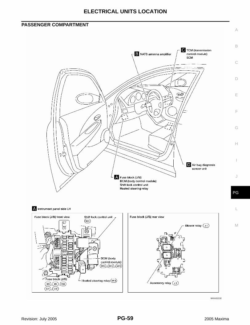
PASSENGER COMPARTMENT
WKIA3221E
PG-60
ELECTRICAL UNITS LOCATION
Revision: July 2005 2005 Maxima
WKIA0476E
ELECTRICAL UNITS LOCATION
PG-61
C
D
E
F
G
H
I
J
L
M
A
B
PG
Revision: July 2005 2005 Maxima
Fuse EKS009IC
● If fuse is blown, be sure to eliminate cause of incident beforeinstalling new fuse.
● Use fuse of specified rating. Never use fuse of more than speci-fied rating.
● Do not partially install fuse; always insert it into fuse holder prop-erly.
● Remove fuse for “ELECTRICAL PARTS (BAT)” if vehicle is notused for a long period of time.
Fusible Link EKS009ID
A melted fusible link can be detected either by visual inspection or by feeling with finger tip. If its condition isquestionable, use circuit tester or test lamp.CAUTION:● If fusible link should melt, it is possible that critical circuit (power supply or large current carrying
circuit) is shorted. In such a case, carefully check and eliminate cause of incident.● Never wrap outside of fusible link with vinyl tape. ● Never let fusible link touch any other wiring harness, vinyl or rubber parts.
Circuit Breaker (Built Into BCM) EKS009IE
For example, when current is 30A, the circuit is broken within 8 to 20seconds.A circuit breaker is used for the following systems:● Power seat● Power windows● Power door locks● Remote keyless entry system
CEL083
SBF284E
PG-62
HARNESS CONNECTOR
Revision: July 2005 2005 Maxima
HARNESS CONNECTOR PFP:B4341
Description EKS009IF
HARNESS CONNECTOR (TAB-LOCKING TYPE)● The tab-locking type connectors help prevent accidental looseness or disconnection.● The tab-locking type connectors are disconnected by pushing or lifting the locking tab(s). Refer to the
illustration below.Refer to the next page for description of the slide-locking type connector.CAUTION:Do not pull the harness or wires when disconnecting the connector.[Example]
SEL769DA
HARNESS CONNECTOR
PG-63
C
D
E
F
G
H
I
J
L
M
A
B
PG
Revision: July 2005 2005 Maxima
HARNESS CONNECTOR (SLIDE-LOCKING TYPE)● A new style slide-locking type connector is used on certain systems and components, especially those
related to OBD.● The slide-locking type connectors help prevent incomplete locking and accidental looseness or discon-
nection.● The slide-locking type connectors are disconnected by pushing or pulling the slider. Refer to the illustra-
tion below.CAUTION:● Do not pull the harness or wires when disconnecting the connector.● Be careful not to damage the connector support bracket when disconnecting the connector.[Example]
HARNESS CONNECTOR (DIRECT-CONNECT SRS COMPONENT TYPE)● SRS direct-connect type harness connectors are used on certain SRS components such as air bag mod-
ules and seat belt pre-tensioners.● Always pull up to release black locking tab prior to removing connector from SRS component.● Always push down to lock black locking tab after installing connector to SRS component. When locked,
the black locking tab is level with the connector housing.
AEL299C
PG-64
HARNESS CONNECTOR
Revision: July 2005 2005 Maxima
CAUTION:● Do not pull the harness or wires when removing connectors
from SRS components.
WHIA0103E
ELECTRICAL UNITS
PG-65
C
D
E
F
G
H
I
J
L
M
A
B
PG
Revision: July 2005 2005 Maxima
ELECTRICAL UNITS PFP:23710
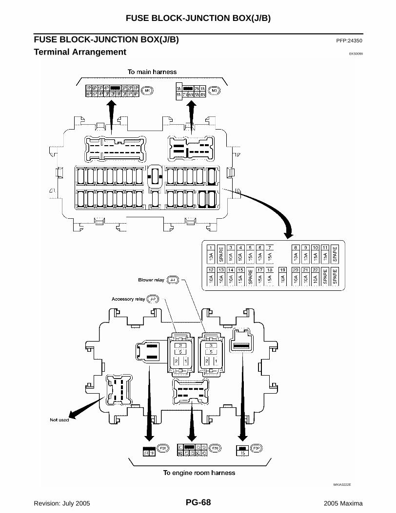
Terminal Arrangement EKS009IG
WKIA4261E
PG-66
STANDARDIZED RELAY
Revision: July 2005 2005 Maxima
STANDARDIZED RELAY PFP:25230
Description EKS009IH
NORMAL OPEN, NORMAL CLOSED AND MIXED TYPE RELAYSRelays can mainly be divided into three types: normal open, normal closed and mixed type relays.


![ELECTRICAL & POWER CONTROL PCSB A - boredmderboredmder.com/FSMs/Nissan/Altima/2008/PCS.pdf · PCS-4 < FUNCTION DIAGNOSIS > [IPDM E/R] RELAY CONTROL SYSTEM System Description](https://static.documents.pub/doc/80x56/5e1a60bde0ab0c6c750fa6d2/electrical-power-control-pcsb-a-pcs-4-function-diagnosis-ipdm.jpg)


![ELECTRICAL & POWER CONTROL PCSB A - The Nissan Path · PCS-10 < FUNCTION DIAGNOSIS > [IPDM E/R] DIAGNOSIS SYSTEM (IPDM E/R) DIAGNOSIS SYSTEM (IPDM E/R) Diagnosis Description](https://static.documents.pub/doc/80x56/5c03522109d3f2a5198cdbf0/electrical-power-control-pcsb-a-the-nissan-pcs-10-function-diagnosis-.jpg)


