CA 12-12a 23 FEBRUARY 2006 Page 1 of 23 Section/division Accident and Incident Investigation Division Form Number: CA 12-12a AIRCRAFT ACCIDENT REPORT AND EXECUTIVE SUMMARY Reference: CA18/2/3/8745 Aircraft Registration ZS-HWH Date of Accident 1 February 2010 Time of Accident 1000Z Type of Aircraft Hughes 269C (Helicopter) Type of Operation Training Pilot-in-command Licence Type Commercial (H) Age 21 Licence Valid Yes Pilot-in-command Flying Experience Total Flying Hours 202.9 Hours on Type 176.3 Last point of departure Wonderboom Aerodrome (FAWB) Gauteng Next point of intended landing Wonderboom Aerodrome (FAWB) Gauteng Location of the accident site with reference to easily defined geographical points (GPS readings if possible) Helicopter landing zone at Wonderboom Aerodrome (GPS coordinates S 25°39’35.24” E 028°12’57.52”) Meteorological Information Wind: southerly at 5 kts; Visibility: >10 km; Temperature: 28 °C; Cloud cover: nil Number of people on board 2+0 No. of people injured 1+0 No. of people killed 0 Synopsis On 01 February 2010 at approximately 1000Z the pilot, accompanied by a flight instructor, were preparing for take-off on a training flight to assess the skills level of the pilot for a game rating. During the magneto-check at approximately 3200 engine RPM, while still on the ground, the aircraft started resonating on the ground. The pilot immediately closed the throttle. The helicopter then became uncontrollable and the tail rotor blades made contact with the ground. The helicopter spun in a clockwise direction and the main rotor blades severed the tail boom from the helicopter. The rest of the helicopter was destroyed during the sequence of the accident. No damage was caused to the helicopter landing pad. The flight instructor sustained minor injuries during the sequence of the accident. Probable Cause Severe ground resonance as a result of incorrect landing gear damper pressures rendered the helicopter uncontrollable and rotor contact followed. Contributing factor Failure of the landing gear damper attachment points owing to the severe ground resonance. IARC Date Release Date
Transcript
CA 12-12a 23 FEBRUARY 2006 Page 1 of 23
Section/division Accident and Incident Investigation Division Form Number: CA 12-12a
AIRCRAFT ACCIDENT REPORT AND EXECUTIVE SUMMARY
Reference: CA18/2/3/8745
Aircraft Registration ZS-HWH Date of Accident 1 February 2010 Time of Accident 1000Z
Type of Aircraft Hughes 269C (Helicopter) Type of Operation Training
Pilot-in-command Licence Type Commercial (H) Age 21 Licence Valid Yes
Pilot-in-command Flying Experience Total Flying Hours 202.9 Hours on Type 176.3
Last point of departure Wonderboom Aerodrome (FAWB) Gauteng
Next point of intended landing Wonderboom Aerodrome (FAWB) Gauteng
Location of the accident site with reference to eas ily defined geographical points (GPS readings if possible)
Helicopter landing zone at Wonderboom Aerodrome (GPS coordinates S 25°39’35.24” E 028°12’57.52”)
Meteorological Information Wind: southerly at 5 kts; Visibility: >10 km; Temperature: 28 °C; Cloud cover: nil
Number of people on board 2+0 No. of people injured 1+0 No. of people killed 0
Synopsis
On 01 February 2010 at approximately 1000Z the pilot, accompanied by a flight instructor, were preparing for take-off on a training flight to assess the skills level of the pilot for a game rating. During the magneto-check at approximately 3200 engine RPM, while still on the ground, the aircraft started resonating on the ground. The pilot immediately closed the throttle. The helicopter then became uncontrollable and the tail rotor blades made contact with the ground. The helicopter spun in a clockwise direction and the main rotor blades severed the tail boom from the helicopter. The rest of the helicopter was destroyed during the sequence of the accident. No damage was caused to the helicopter landing pad. The flight instructor sustained minor injuries during the sequence of the accident.
Probable Cause Severe ground resonance as a result of incorrect landing gear damper pressures rendered the helicopter uncontrollable and rotor contact followed. Contributing factor Failure of the landing gear damper attachment points owing to the severe ground resonance. IARC Date Release Date
CA 12-12a 23 FEBRUARY 2006 Page 2 of 23
Section/division Accident and Incident Investigation Division Form Number: CA 12-12a Telephone number: 011-545-1000
AIRCRAFT ACCIDENT REPORT
Name of Owner/Operator : G W A Eiendomme CC Manufacturer : HUGHES HELICOPTER CO. (Schweizer) Model : 269C Nationality : South African Registration Marks : ZS-HWH Place : Wonderboom Aerodrome Date : 1 February 2010 Time : 10:00Z All times given in this report are Co-ordinated Universal Time (UTC) and will be denoted by (Z). South African Standard Time is UTC plus 2 hours. Purpose of the investigation: In terms of Regulation 12.03.1 of the Civil Aviation Regulations (1997) this report was compiled in the interest of the promotion of aviation safety and the reduction of the risk of aviation accidents or incidents and not to establish legal liability. Disclaimer: This report is produced without prejudice to the rights of the CAA, which are reserved.
1. FACTUAL INFORMATION 1.1 History of flight 1.1.1 On 1 February 2010 at approximately 1000Z, the pilot accompanied by an instructor
was preparing for take-off on a training flight from Wonderboom Aerodrome (FAWB) to assess the skills level of the pilot for game rating.
1.1.2 While completing the before take-off checklist, at the point where they had to check
the magnetos for serviceability, the engine RPM of the helicopter was increased to 3200 RPM. At this point, the pilot experienced excessive resonance of the helicopter.
1.1.3 The instructor immediately instructed the pilot to close the throttle, as there was no
time for the instructor to take over control of the aircraft. The resonance made the helicopter uncontrollable for the pilot.
1.1.4 The tail rotor blades then made contact with the landing surface, the helicopter spun
around and the main rotor blades severed the tail boom. The helicopter was destroyed during the sequence of the accident.
CA 12-12a 23 FEBRUARY 2006 Page 3 of 23
1.2 Injuries to persons
Injuries Pilot Crew Pass. Other Fatal - - - - Serious - - - - Minor 1 - - - None - 1 - -
1.3 Damage to aircraft 1.3.1 The helicopter was destroyed during the sequence of the accident. 1.4 Other damage 1.4.1 No other damage was caused during the sequence of the accident. 1.5 Personnel information 1.5.1 Instructor pilot
Nationality South African Gender Male Age 33 Licence Number **************** Licence Type Commercial (H) License valid Yes Type Endorsed Yes Ratings Instructor, instrument rating, under sling rating Medical Expiry Date 30 June 2010 Restrictions Corrective lenses Previous Accidents None
Flying experience
Total hours 3900 Total past 90 days 120 Total on type past 90 days 0 Total on type 70
1.5.2 Pilot
Nationality South African Gender Male Age 21 Licence number **************** License type Commercial (H) Licence valid Yes Type endorsed Yes Ratings None Medical expiry date 31 December 2010 Restrictions None Previous accidents None reported
CA 12-12a 23 FEBRUARY 2006 Page 4 of 23
Flying experience:
Total hours 202.9 Total past 90 days 3.3 Total on type past 90 days 0.7 Total on type 176.3
1.6 Aircraft information
Airframe: Type Hughes 269C Serial number 700023 Manufacturer Hughes Helicopter CO. Year of manufacture 1987 Total airframe hours (at time of accident) 10901.4 Last MPI (hours & date) 10808.3 9 September 2009 Hours since last MPI 93.1 C of A (issue date) 14 March 1990 C of R (issue date) (present owner) 22 September 2008 Operating categories Standard
Engine: Type Lycoming HIO-360-D1A Serial number L-21307-51A Hours since new 2131.4 Hours since overhaul 842.4
1.7 Meteorological information
Wind direction Southerly Wind speed 5 kts Visibility >10 km Temperature 28 °C Cloud cover Clear Sky Cloud base Nil Dew point Unknown
1.7.1 The meteorological information was obtained from the pilot questionnaire after the
accident. 1.8 Aids to navigation 1.8.1 The aircraft was equipped with the standard navigational equipment as per the
minimum equipment list approved by the Regulator. There were no recorded defects reported prior to the accident.
1.9 Communications 1.9.1 The helicopter was equipped with standard communications equipment as per the
minimum equipment list by the Regulator. There were no recorded defects to
CA 12-12a 23 FEBRUARY 2006 Page 5 of 23
communications equipment prior to the flight. The pilot communicated his intentions to Wonderboom Tower on VHF radio frequency 120.6 before the accident.
1.10 Aerodrome information
Aerodrome location 6 km north of Pretoria Aerodrome Co-ordinates S 25°39’19.1” E028°13’16.8” Aerodrome elevation 4095 feet Runway designations 11/29 06/24 Runway dimensions 1828 m x 30 m 1280 m x 22 m Runway used Helicopter landing zone Runway surface Paved bricks (Helipad) Approach facilities Not applicable
1.11 Flight recorders 1.11.1 The helicopter was not fitted with a cockpit voice recorder (CVR) or a flight data
recorder (FDR) and neither was required by regulations to be fitted to this type of helicopter.
1.12 Wreckage and impact information 1.12.1 Impact damage The aircraft was on the ground when the accident occurred. Marks on the ground
indicated that the tail rotor blades had made contact with the brick paved surface of the helicopter landing pad. Broken pieces of the tail rotor blades were found in line and approximately 20 metres away from the marks on the ground. Marks on the landing surface clearly indicated the helicopter had spun clockwise on the helicopter landing zone. Small pieces of debris were found in a radius of approximately 25 metres from the main wreckage.
1.12.2 Fuselage The fuselage was destroyed during the sequence of the accident. (See Figure 1.)
The tail boom was severed from the fuselage and was found approximately 2 metres from the main wreckage. The left-hand rear landing gear damper’s bottom attachment point on the landing gear skid was broken while the left-hand front gear damper’s top attachment point on the damper was broken. (See Figure 2.) These broken attachment points were caused by the accident sequence.
CA 12-12a 23 FEBRUARY 2006 Page 6 of 23
Figure 1 Damage caused to the fuselage of the helicopter
(a) (b)
Figure 2 Damage to the left-hand rear (a) and left-hand front (b) damper attachment points
1.12.3 Main rotor blades The rotor blades were still attached to the rotor mast although all three main rotor
drag dampers were destroyed. Damage to the main rotor blade tips indicated that the main rotor blades had made contact with the brick-paved helicopter landing pad. Impact damage marks were visible on all three main rotor blades. The tail rotor blades were destroyed during the accident sequence. Marks indicating that the tail rotor blades had made contact with the landing surface were clearly visible on the landing surface. (See Figure 3.)
CA 12-12a 23 FEBRUARY 2006 Page 7 of 23
(a) (b)
Figure 3 Damage to the tail rotor blades (a) and contact marks (b) with the landing surface
1.12.4 Engine There was no visible damage to the engine. 1.12.5 Cockpit seats There was no damage to either of the helicopters seats. 1.13 Medical and pathological information 1.13.1 The flight instructor sustained a laceration to his head but was discharged from
hospital on the same day. 1.14 Fire 1.14.1 There was no pre- or post-impact fire. 1.15 Survival aspects 1.15.1 This accident was regarded as survivable due to the low impact forces on the
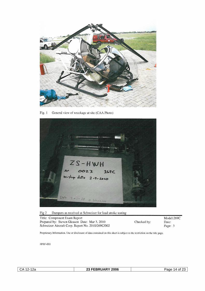
cockpit area and because the occupants were both wearing safety harnesses. 1.16 Tests and research 1.16.1 The four landing gear dampers were removed from the wreckage and were
forwarded to the helicopter manufacturer for load stroke tests. The tests were conducted under supervision of the Federal Aviation Administration (FAA). A load stroke test is a compression test of the dampers. It is essentially a static test since it takes about a minute and a half to make the compression from free, extended, to fully compressed. The compression dimensional change (stroke) is measured and the compression load during the stroke cycle and extension cycle is documented and graphed. Comparison of standard dampers and mishap units shows if the subject units were properly serviced.
1.16.2 The tests revealed that all four landing gear dampers were improperly charged.
CA 12-12a 23 FEBRUARY 2006 Page 8 of 23
Three of the four dampers were in excess of full stroke limits and the fourth was out of limits for the intermediate range. The effect of excessive pressure in the dampers is a loss of damping and a lack of attenuation of main rotor oscillations. (See Appendix A for complete report.)
1.16.3 For a description of the damper operation see Appendix B . 1.17 Organizational and management information 1.17.1 This was a training flight. 1.17.2 The last mandatory Inspection was certified on 10 September 2009 at 10808.3
hours by a CAA-approved Aircraft Maintenance Organization (AMO) in possession of a valid approval certificate.
1.18 Additional information 1.18.1The pilot operating handbook (POH) page 7-14 paragraph 7-12 recommends the
following daily inspection on the landing gear dampers: “7-12 LANDING GEAR DAMPERS – INSPECTION
“Four poppet type nitrogen charged hydraulic units in the landing gear assembly dampen landing shock and prevent ground resonance. The dampers are mounted between the helicopter centerframe section and the landing gear skids (two for each skid, left- and right-hand sides). Perform the following check during each Daily Inspection to ensure proper extension of dampers.
Note: Ensure that the helicopter is in an empty-weight configuration (no passengers or cargo aboard) but with full fuel load. Visually inspect landing gear dampers for leakage. Replace damper if loss of hydraulic oil is noted. Observe stance of the helicopter. If stance is nose down or if extension of the aft dampers appears to be unusual, perform the following checks. Raise and lower the tail boom above and below the normal at-rest position three times. On the last cycle, slowly lower the tail boom to an at-rest position and observe stance of helicopter. If stance of helicopter or extension of aft dampers still appears unusual, perform the following steps. Measure distance from shoulder of damper upper cap to top edge of damper bottom cap on all dampers. Replace any damper measuring less than the following dimensions in Table 7-3.”
1.18.2 The four landing gear dampers are attached between the outboard ends of the
crossbeams and the skid strut assembly. The landing gear dampers absorb and dissipate landing shocks and recoil shocks that are produced when the helicopter takes off; they also help prevent ground resonance and serve as structural
CA 12-12a 23 FEBRUARY 2006 Page 9 of 23
members to support the weight of the helicopter during engagement, disengagement and while static.
1.18.3 The pilot mentioned to the investigator on the last landing before the accident that
he experienced some resonance during landing. The pilot then inspected the helicopter after the landing but could not find any abnormalities.
1.18.4 Damper operation
See Appendix B for a description of the damper operation.
Figure 4 Damper cross section
Table 7-3. Landing Gear Damper Dimensions
With main tank only With Auxiliary Tank Kit Installed Left Right Left Right
Aft 8.4 8.0* 8.0* 8.0* Forward 9.1 8.7 8.7 8.7
* When dimensions are less than 8.0 inches, recheck extension per 100-hour inspection method (Refer to HMI) before replacing aft damper. 1.18.4 This prescribed inspection was not done before the accident flight.
CA 12-12a 23 FEBRUARY 2006 Page 10 of 23
1.19 Useful or effective investigation techniques 1.18.1 None 2. ANALYSIS 2.1 Verification of the pilot’s personal file confirms he was in possession of a valid
commercial pilot license (helicopter). The pilot had a total of 176.3 hours on the Hughes 269 helicopter. At the time of the accident, the pilot was in possession of a valid medical certificate that imposes no restrictions.
2.2 Both occupants survived the accident with only the instructor sustaining a head
laceration during the sequence of the accident. 2.3 The accident helicopter was properly certified, equipped, and maintained in
accordance with prescribed regulations. The recovered components showed no evidence of any pre-existing system, structural or power plant failure.
2.4 A landing gear damper load stroke test done on all four dampers after the accident
revealed all four dampers were improperly charged. The left-hand front and rear damper mounting points were broken after the accident because of the accident sequence.
2.5 The effect of excessive pressure in the dampers is a loss of damping and a lack of
attenuation of main rotor oscillations. 2.6 Marks indicating that the tail rotor blade had made contact with the landing surface
were clearly visible on the scene of the accident. 2.7 The engine was found attached to the helicopter with no evidence of fire, structural
damage or foreign object damage. 2.8 According to the weather information obtained from the pilot’s questionnaire, the
weather was fine with clear sky at the time of the accident. 3. CONCLUSION 3.1 Findings 3.1.1 The pilot was properly certified and qualified according to current regulations. 3.1.2 The accident aircraft was properly certified, equipped and maintained in accordance
with current regulations. Recovered components showed no evidence of structural, engine or system failure other than those as a result of the accident sequence.
3.1.3 Although the aircraft was destroyed during the sequence of the accident, the
accident was regarded as survivable due to the low impact forces on the cockpit area.
3.1.4 It would appear that the incorrect pressure of the landing gear dampers caused the
out of control resonance of the helicopter. The effect of incorrect pressures in the dampers is a loss of damping and a lack of attenuation of main rotor oscillations.
CA 12-12a 23 FEBRUARY 2006 Page 11 of 23
During this resonance, the left-hand dampers both failed, causing the tail rotor blades to make contact with the landing surface. This contact destroyed the tail rotor blades, causing the helicopter to spin around, out of control, with the resultant damage to the helicopter.
3.1.5 The weather did not contribute to the accident.
3.2 Probable cause/s
Severe ground resonance as a result of incorrect landing gear damper pressures rendered the helicopter uncontrollable and rotor contact followed.
3.3 Contributing factor
Failure of the landing gear damper attachment points as a result of the severe ground resonance.
4. SAFETY RECOMMENDATIONS 4.1 It is recommended the Airworthiness Department within the SACAA inform all
maintenance providers of the Hughes 296 Helicopter to completely overhaul the dampers and not “recharge” them. (This was recommended by the manufacturer within the report after the load stroke tests.) Overhaul facilities need to ensure that the fluid levels and gas pressures are matched and appropriate for the damper configuration being assembled.
5. APPENDICES 5.1 Appendix A Component Examination Report. 5.2 Appendix B Description of the damper operation.
Report reviewed and amended by the Advisory Safety Panel on18 May 2010
-END-
CA 12-12a 23 FEBRUARY 2006 Page 12 of 23
Appendix A
CA 12-12a 23 FEBRUARY 2006 Page 13 of 23
CA 12-12a 23 FEBRUARY 2006 Page 14 of 23
CA 12-12a 23 FEBRUARY 2006 Page 15 of 23
CA 12-12a 23 FEBRUARY 2006 Page 16 of 23
CA 12-12a 23 FEBRUARY 2006 Page 17 of 23
CA 12-12a 23 FEBRUARY 2006 Page 18 of 23
CA 12-12a 23 FEBRUARY 2006 Page 19 of 23
CA 12-12a 23 FEBRUARY 2006 Page 20 of 23
CA 12-12a 23 FEBRUARY 2006 Page 21 of 23
CA 12-12a 23 FEBRUARY 2006 Page 22 of 23
CA 12-12a 23 FEBRUARY 2006 Page 23 of 23
Appendix B
Landing Gear Damper operation: Service Training Manual Chapter 4 page 9.


![12a -OilFieldSafetyNEO1[1]..](https://static.documents.pub/doc/80x56/55cf97e3550346d03394398e/12a-oilfieldsafetyneo11.jpg)


