Secure PLC Coding Practices: Top 20 List Version 1.0 (15 June 2021) 1 / 2 1. Modularize PLC Code Split PLC code into modules, using different function blocks (sub-routines). Test modules independently. 2. Track operating modes Keep the PLC in RUN mode. If PLCs are not in RUN mode, there should be an alarm to the operators. 3. Leave operational logic in the PLC wherever feasible Leave as much operational logic e.g., totalizing or integrating, as possible directly in the PLC. The HMI does not get enough updates to do this well. 4. Use PLC flags as integrity checks Put counters on PLC error flags to capture any math problems. 5. Use cryptographic and / or checksum integrity checks for PLC code Use cryptographic hashes, or checksums if cryptographic hashes are unavailable, to check PLC code integrity and raise an alarm when they change. 6. Validate timers and counters If timers and counters values are written to the PLC program, they should be validated by the PLC for reasonableness and verify backward counts below zero. 7. Validate and alert for paired inputs / outputs If you have paired signals, ensure that both signals are not asserted together. Alarm the operator when input / output states occur that are physically not feasible. Consider making paired signals independent or adding delay timers when toggling outputs could be damaging to actuators. 8. Validate HMI input variables at the PLC level, not only at HMI HMI access to PLC variables can (and should) be restricted to a valid operational value range at the HMI, but further cross-checks in the PLC should be added to prevent, or alert on, values outside of the acceptable ranges which are programmed into the HMI. 9. Validate indirections Validate indirections by poisoning array ends to catch fence-post errors. 10. Assign designated register blocks by function (read/write/validate) Assign designated register blocks for specific functions in order to validate data, avoid buffer overflows and block unauthorized external writes to protect controller data. 11. Instrument for plausibility checks Instrument the process in a way that allows for plausibility checks by cross-checking different measurements. 12. Validate inputs based on physical plausibility Ensure operators can only input what’s practical or physically feasible in the process. Set a timer for an operation to the duration it should physically take. Consider alerting when there are deviations. Also alert when there is unexpected inactivity.
Transcript
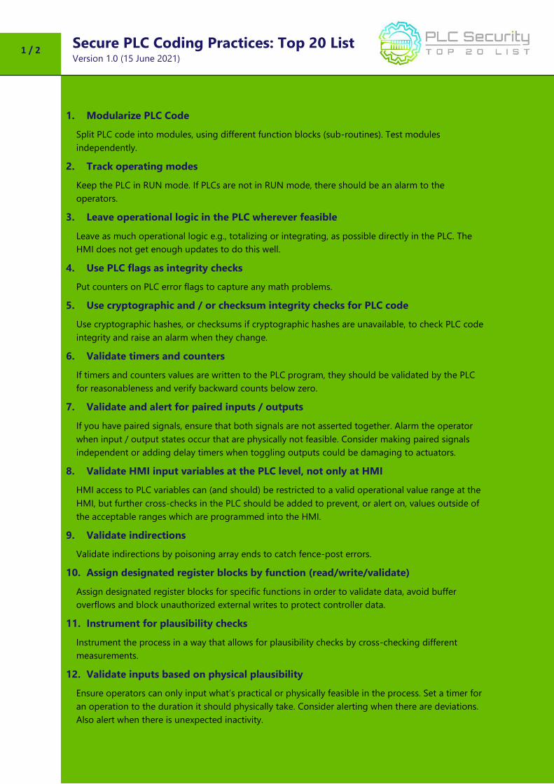
Secure PLC Coding Practices: Top 20 List Version 1.0 (15 June 2021)
1 / 2
1. Modularize PLC Code
Split PLC code into modules, using different function blocks (sub-routines). Test modules
independently.
2. Track operating modes
Keep the PLC in RUN mode. If PLCs are not in RUN mode, there should be an alarm to the
operators.
3. Leave operational logic in the PLC wherever feasible
Leave as much operational logic e.g., totalizing or integrating, as possible directly in the PLC. The
HMI does not get enough updates to do this well.
4. Use PLC flags as integrity checks
Put counters on PLC error flags to capture any math problems.
5. Use cryptographic and / or checksum integrity checks for PLC code
Use cryptographic hashes, or checksums if cryptographic hashes are unavailable, to check PLC code
integrity and raise an alarm when they change.
6. Validate timers and counters
If timers and counters values are written to the PLC program, they should be validated by the PLC
for reasonableness and verify backward counts below zero.
7. Validate and alert for paired inputs / outputs
If you have paired signals, ensure that both signals are not asserted together. Alarm the operator
when input / output states occur that are physically not feasible. Consider making paired signals
independent or adding delay timers when toggling outputs could be damaging to actuators.
8. Validate HMI input variables at the PLC level, not only at HMI
HMI access to PLC variables can (and should) be restricted to a valid operational value range at the
HMI, but further cross-checks in the PLC should be added to prevent, or alert on, values outside of
the acceptable ranges which are programmed into the HMI.
9. Validate indirections
Validate indirections by poisoning array ends to catch fence-post errors.
10. Assign designated register blocks by function (read/write/validate)
Assign designated register blocks for specific functions in order to validate data, avoid buffer
overflows and block unauthorized external writes to protect controller data.
11. Instrument for plausibility checks
Instrument the process in a way that allows for plausibility checks by cross-checking different
measurements.
12. Validate inputs based on physical plausibility
Ensure operators can only input what’s practical or physically feasible in the process. Set a timer for
an operation to the duration it should physically take. Consider alerting when there are deviations.
Also alert when there is unexpected inactivity.
Secure PLC Coding Practices: Top 20 List Version 1.0 (15 June 2021)
2 / 2
13. Disable unneeded / unused communication ports and protocols
PLC controllers and network interface modules generally support multiple communication protocols
that are enabled by default. Disable ports and protocols that are not required for the application.
14. Restrict third-party data interfaces
Restrict the type of connections and available data for 3rd party interfaces. The connections and/or
data interfaces should be well defined and restricted to only allow read/write capabilities for the
required data transfer.
15. Define a safe process state in case of a PLC restart
Define safe states for the process in case of PLC restarts (e.g., energize contacts, de-energize, keep
previous state).
16. Summarize PLC cycle times and trend them on the HMI
Summarize PLC cycle time every 2-3 seconds and report to HMI for visualization on a graph.
17. Log PLC uptime and trend it on the HMI
Log PLC uptime to know when it’s been restarted. Trend and log uptime on the HMI for diagnostics.
18. Log PLC hard stops and trend them on the HMI
Store PLC hard stop events from faults or shutdowns for retrieval by HMI alarm systems to consult
before PLC restarts. Time sync for more accurate data.
19. Monitor PLC memory usage and trend it on the HMI
Measure and provide a baseline for memory usage for every controller deployed in the production
environment and trend it on the HMI.
20. Trap false negatives and false positives for critical alerts
Identify critical alerts and program a trap for those alerts. Set the trap to monitor the trigger
conditions and the alert state for any deviation.
About the Secure PLC Programming project
Secure PLC Coding Practices: Details Version 1.0 (15 June 2021)
1 / 42
1. Modularize PLC Code
Split PLC code into modules, using different function blocks (sub-routines). Test
modules independently.
Security Objective Target Group
Integrity of PLC logic Product Supplier
Guidance
Do not program the complete PLC logic in one place e.g., in the main Organization Block or main
routine. Instead, split it into different function blocks (sub-routines) and monitor their execution time
and their size in Kb.
Create separate segments for logic that functions independently. This helps in input validation,
access control management, integrity verification etc.
Modularized code also facilitates testing and keeping track of the integrity of code modules. If the
code inside the module has been meticulously tested, any modifications to these modules can be
verified against the hash of the original code, e.g., by saving a hash of each of these modules (when
that’s an option in the PLC). This way, modules can be validated during the FAT/SAT or if the integrity
of the code is in question after an incident.
Example
Gas Turbine logic is segregated into “startup”, “Inlet Guide Vanes Control”, “Bleed Valve Control” etc.
so that you can apply standard logic systematically. This also helps in troubleshooting quickly if there
were to be a security incident.
Custom function blocks that are tested rigorously can be re-used without alteration (and alerted if
change attempts are made) and locked against abuse/misuse with a password/digital signature.
Why?
Beneficial for…? Why?
Security Facilitates the detection of newly added portions of code that could be malicious. Helps in logic standardization, consistency, and locking against unauthorized modifications.
Reliability Helps control the program flow sequence and avoid loops, which could cause the logic to not react properly or crash.
Maintenance
Modular code is not only easier to debug (modules can be tested independently) but also easier to maintain and update. Also, the modules may be used for additional PLCs, thus allowing for common code to be used and identified in separate PLCs. This can aid maintenance personnel with quickly recognizing common modules during troubleshooting.
Secure PLC Coding Practices: Details Version 1.0 (15 June 2021)
2 / 42
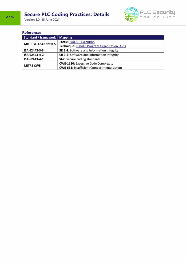
References
Standard / framework Mapping
MITRE ATT&CK for ICS Tactic: TA002 - Execution Technique: T0844 - Program Organization Units
ISA 62443-3-3 SR 3.4: Software and information integrity
ISA 62443-4-2 CR 3.4: Software and information integrity
Secure PLC Coding Practices: Details Version 1.0 (15 June 2021)
3 / 42
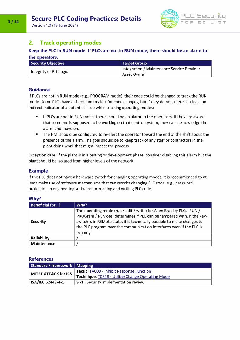
2. Track operating modes
Keep the PLC in RUN mode. If PLCs are not in RUN mode, there should be an alarm to
the operators.
Security Objective Target Group
Integrity of PLC logic Integration / Maintenance Service Provider Asset Owner
Guidance
If PLCs are not in RUN mode (e.g., PROGRAM mode), their code could be changed to track the RUN
mode. Some PLCs have a checksum to alert for code changes, but if they do not, there’s at least an
indirect indicator of a potential issue while tracking operating modes:
If PLCs are not in RUN mode, there should be an alarm to the operators. If they are aware
that someone is supposed to be working on that control system, they can acknowledge the
alarm and move on.
The HMI should be configured to re-alert the operator toward the end of the shift about the
presence of the alarm. The goal should be to keep track of any staff or contractors in the
plant doing work that might impact the process.
Exception case: If the plant is in a testing or development phase, consider disabling this alarm but the
plant should be isolated from higher levels of the network.
Example
If the PLC does not have a hardware switch for changing operating modes, it is recommended to at
least make use of software mechanisms that can restrict changing PLC code, e.g., password
protection in engineering software for reading and writing PLC code.
Why?
Beneficial for…? Why?
Security
The operating mode (run / edit / write; for Allen Bradley PLCs: RUN / PROGram / REMote) determines if PLC can be tampered with. If the key-switch is in REMote state, it is technically possible to make changes to the PLC program over the communication interfaces even if the PLC is running.
Reliability /
Maintenance /
References
Standard / framework Mapping
MITRE ATT&CK for ICS Tactic: TA009 - Inhibit Response Function Technique: T0858 - Utilize/Change Operating Mode
Secure PLC Coding Practices: Details Version 1.0 (15 June 2021)
4 / 42
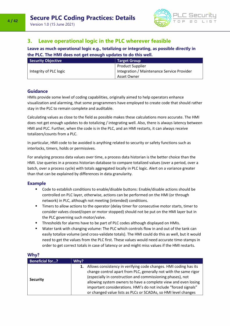
3. Leave operational logic in the PLC wherever feasible
Leave as much operational logic e.g., totalizing or integrating, as possible directly in
the PLC. The HMI does not get enough updates to do this well.
Security Objective Target Group
Integrity of PLC logic Product Supplier Integration / Maintenance Service Provider Asset Owner
Guidance
HMIs provide some level of coding capabilities, originally aimed to help operators enhance
visualization and alarming, that some programmers have employed to create code that should rather
stay in the PLC to remain complete and auditable.
Calculating values as close to the field as possible makes these calculations more accurate. The HMI
does not get enough updates to do totalizing / integrating well. Also, there is always latency between
HMI and PLC. Further, when the code is in the PLC, and an HMI restarts, it can always receive
totalizers/counts from a PLC.
In particular, HMI code to be avoided is anything related to security or safety functions such as
interlocks, timers, holds or permissives.
For analyzing process data values over time, a process data historian is the better choice than the
HMI. Use queries in a process historian database to compare totalized values (over a period, over a
batch, over a process cycle) with totals aggregated locally in PLC logic. Alert on a variance greater
than that can be explained by differences in data granularity.
Example
Code to establish conditions to enable/disable buttons: Enable/disable actions should be
controlled on PLC layer, otherwise, actions can be performed on the HMI (or through
network) in PLC, although not meeting (intended) conditions.
Timers to allow actions to the operator (delay timer for consecutive motor starts, timer to
consider valves closed/open or motor stopped) should not be put on the HMI layer but in
the PLC governing such motor/valve.
Thresholds for alarms have to be part of PLC codes although displayed on HMIs.
Water tank with changing volume: The PLC which controls flow in and out of the tank can
easily totalize volume (and cross-validate totals). The HMI could do this as well, but it would
need to get the values from the PLC first. These values would need accurate time-stamps in
order to get correct totals in case of latency or and might miss values if the HMI restarts.
Why?
Beneficial for…? Why?
Security
1. Allows consistency in verifying code changes. HMI coding has its change control apart from PLC, generally not with the same rigor (especially in construction and commissioning phases), not allowing system owners to have a complete view and even losing important considerations. HMI’s do not include “forced signals” or changed value lists as PLCs or SCADAs, so HMI level changes
Secure PLC Coding Practices: Details Version 1.0 (15 June 2021)
5 / 42
Beneficial for…? Why?
are more difficult to be detected, practically impossible to be part of an authorization change management plan.
2. For an attacker, it is harder to manipulate totals distributed over many PLCs than to manipulate totals all calculated in the HMI.
3. If a portion of the enable/disable functions are not in the PLC, attackers might be able to manipulate the PLC and I/O without having to work the HMI portion as the proper information is already obfuscated on the operator screen.
Reliability
1. Calculations are more efficient and accurate if closer to the field. Also, totals and counts will still be available if HMI restarts (PLCs do not restart as often and usually store these values in non-volatile memory).
2. Different sources for inputs and interlocks may mean non expected failures. There can be different technologies for HMIs in a plant (SCADA layer, but also field controller panels) and changes in one of those will fail to be disseminated through the rest of layers, leading to inconsistences in visualization and possible failures in operation.
Maintenance Coding is easy to understand and transfer from PLC to PLC, not so much from HMIs to HMIs.
References
Standard / framework Mapping
MITRE ATT&CK for ICS Tactic: TA010 - Impair Process Control Technique: T0836 - Modify Parameter
Secure PLC Coding Practices: Details Version 1.0 (15 June 2021)
6 / 42
4. Use PLC flags as integrity checks
Put counters on PLC error flags to capture any math problems.
Security Objective Target Group
Integrity of PLC logic Product Supplier Integration / Maintenance Service Provider
Guidance
If the PLC code was working fine but suddenly does a divide by zero, investigate. If something is
communicating peer to peer from another PLC and the function/logic does a divide by zero when it
wasn’t expected, investigate.
Most programmers will ignore the issue as a math error or worse yet, might presume their code is
perfect and let the PLC enter a hard fault state. During code development, engineers need to test
and validate their code modules (snippets or routines) by inputting data outside of expected bounds.
This may be termed Unit Level Test.
Assign different, locked memory segments for firmware, logic and protocol stack. Test the protocol
stack for abuse cases. Abuse cases could be peculiar flag conditions in a packet header.
Example
PLC faults caused by out of bounds data are very common. This happens, for example, when an input
value causes array indices go out of bounds, or timers with negative presets, or divide by zero
exceptions.
Typical flags of interest are
divide by zero
counter overflow
negative counter or timer preset
I/O scan overrun
Why?
Beneficial for…? Why?
Security
Attacks on PLCs could include changing its logic, activating a new program, testing new code, loading a new process recipe, inserting auxiliary logic to send messages or activating some feature. Since most PLCs do not provide cryptographic integrity checks, flags can be a good indicator if one of the above logic changes happens.
Reliability Flags taken seriously can avoid the PLC running with programming or I/O errors. Also, if an error occurs, the source of the failure is more obvious.
Maintenance /
Secure PLC Coding Practices: Details Version 1.0 (15 June 2021)
7 / 42
References
Standard / framework Mapping
MITRE ATT&CK for ICS Tactic : TA010 - Impair Process Control Technique: T0836 - Modify Parameter
ISA 62443-3-3 SR 3.5: Input Validation SR 3.6: Deterministic Output
ISA 62443-4-2 CR 3.5: Input Validation CR 3.6: Deterministic Output
ISA 62443-4-1 SI-2: Secure coding standards SVV-1: Security requirements testing
MITRE CWE
CWE-128: Wrap-around CWE-190: Integer Overflow CWE-369: Divide by Zero CWE-754: Improper Check for Unusual or Exceptional Conditions
Secure PLC Coding Practices: Details Version 1.0 (15 June 2021)
8 / 42
5. Use cryptographic and / or checksum integrity checks for PLC
code
Use cryptographic hashes, or checksums if cryptographic hashes are unavailable, to
check PLC code integrity and raise an alarm when they change.
Security Objective Target Group
Integrity of PLC logic Product Supplier Integration / Maintenance Service Provider Asset Owner
Guidance
A) Checksums
Where (cryptographic) hashes are not feasible, checksums may be an option. Some PLCs generate a
unique Checksum when code is downloaded into the PLC Hardware. The Checksum should be
documented by the manufacturer / integrator after SAT and be part of warranty / service-conditions.
If the checksum feature is not natively available in the controller, this can also be generated in the
EWS/HMI and probed e.g., once a day to compare with the hash of the original code in the PLC to
verify that they are matching. While this won’t provide real time alerts, it’s good enough to track if
anyone is attempting changes to the PLC code.
The checksum value can also be moved into a PLC register and configured for an alarm when it
changes, the value can be sent to historians etc.
B) Hashes
PLC CPUs generally do not have the processing capacity to generate or check hashes while running.
Attempting a hash might actually cause the PLC to crash. But the PLC’s engineering software might
be able to calculate hashes from the PLC code and save them either in the PLC or somewhere else in
the control system.
Example
PLC vendors that are known to have checksum features:
Siemens (see example)
Rockwell
Also, external software can be used for generating checksums:
Version dog
Asset Guardian
PAS
Siemens implementation example
Example for creating checksums in Siemens S7-1500 PLC:
GetChecksum-Function Block reads actual checksum and with a lightweight script the “SAT-
Checksum” can be stored as reference. A deviance from the Reference-Checksum can be stored with
the Datalog-Function.
Secure PLC Coding Practices: Details Version 1.0 (15 June 2021)
9 / 42
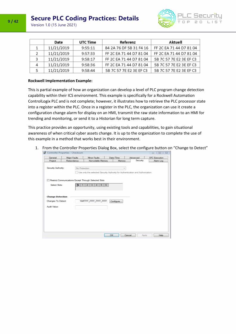
Rockwell Implementation Example:
This is partial example of how an organization can develop a level of PLC program change detection
capability within their ICS environment. This example is specifically for a Rockwell Automation
ControlLogix PLC and is not complete; however, it illustrates how to retrieve the PLC processor state
into a register within the PLC. Once in a register in the PLC, the organization can use it create a
configuration change alarm for display on an HMI, transmit the raw state information to an HMI for
trending and monitoring, or send it to a Historian for long term capture.
This practice provides an opportunity, using existing tools and capabilities, to gain situational
awareness of when critical cyber assets change. It is up to the organization to complete the use of
this example in a method that works best in their environment.
1. From the Controller Properties Dialog Box, select the configure button on “Change to Detect”
Secure PLC Coding Practices: Details Version 1.0 (15 June 2021)
10 / 42
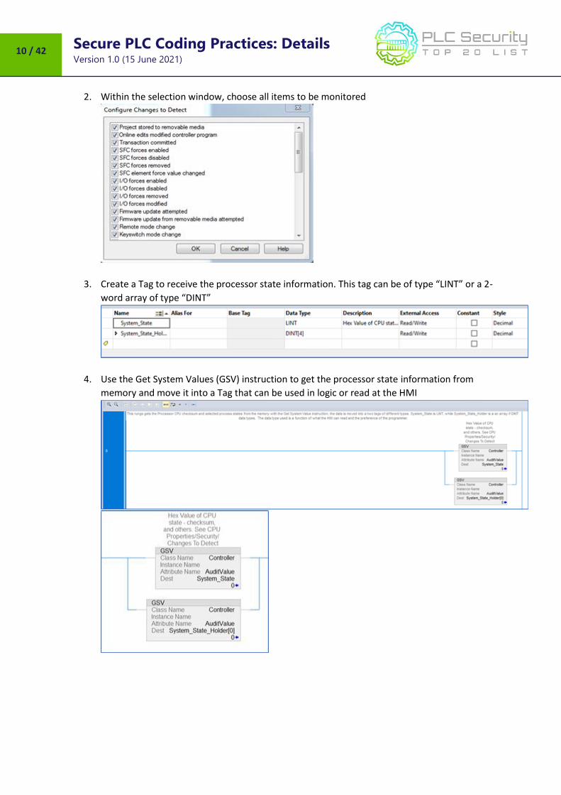
2. Within the selection window, choose all items to be monitored
3. Create a Tag to receive the processor state information. This tag can be of type “LINT” or a 2-
word array of type “DINT”
4. Use the Get System Values (GSV) instruction to get the processor state information from
memory and move it into a Tag that can be used in logic or read at the HMI
Secure PLC Coding Practices: Details Version 1.0 (15 June 2021)
11 / 42
Why?
Beneficial for…? Why?
Security Knowing if PLC code was tampered with is essential for both noticing a compromise and verifying if a PLC is safe to operate after a potential compromise.
Reliability Hashes or checksums can also be a means to verify if the PLC is (still) running code approved by the integrator / manufacturer.
Maintenance /
References
Standard / framework Mapping
MITRE ATT&CK for ICS Tactic: TA002 - Execution, TA010 - Impair Process Control Technique: T0873 - Project File Infection, T0833 - Modify Control Logic
ISA 62443-3-3 SR 3.4 : Software and information integrity
ISA 62443-4-2 CR 3.4 : Software and information integrity EDR 3.12 : Provisioning product supplier roots of trust
Secure PLC Coding Practices: Details Version 1.0 (15 June 2021)
12 / 42
6. Validate timers and counters
If timers and counters values are written to the PLC program, they should be validated
by the PLC for reasonableness and verify backward counts below zero.
Security Objective Target Group
Integrity of PLC variables Integration / Maintenance Service Provider Asset Owner
Guidance
Timers and counters can technically be preset to any value. Therefore, the valid range to preset a
timer or counter needs to should be restricted to meet the operational requirements.
If remote devices such as an HMI write timer or counter values to a program:
do not let the HMI write to the timer or counter directly but go through a validation logic
validate presets and timeout values in the PLC
Validation of timer and counter inputs is easy to directly do in the PLC (without the need for any
network device capable of Deep Packet Inspection), since the PLC “knows” what the process state or
context is. It can validate “what’ it gets and “when” it gets the commands or setpoints.
Example
During PLC startup, timers and counters are usually preset to certain values.
If there is a timer that triggers alarms at 1.3 seconds, but that timer is preset maliciously to 5
minutes, it might not trigger the alarm.
If there is a counter that causes a process to stop when it reaches 10,000 but that is set it to 11,000
from the beginning, the process might not stop.
Why?
Beneficial for…? Why?
Security If I/O, timers, or presets are written directly to I/O, not being validated by the PLC, the PLC validation layer is evaded and the HMI (or other network devices) are assigned an unwarranted level of trust.
Reliability The PLC can also validate when an operator accidentally presets bad timer or counter values.
Maintenance Having valid ranges for timers and counters documented and automatically validated may help when updating logic.
References
Standard / framework Mapping
MITRE ATT&CK for ICS Tactic : TA010 - Impair Process Control Technique: T0836 - Modify Parameter
Secure PLC Coding Practices: Details Version 1.0 (15 June 2021)
13 / 42
7. Validate and alert for paired inputs / outputs
If you have paired signals, ensure that both signals are not asserted together. Alarm the
operator when input / output states occur that are physically not feasible. Consider
making paired signals independent or adding delay timers when toggling outputs
could be damaging to actuators.
Security Objective Target Group
Integrity of PLC variables Resilience
Product Supplier Integration / Maintenance Service Provider
Guidance
Paired inputs or outputs are those that physically cannot happen at the same time; they are mutually
exclusive. Though paired signals cannot be asserted at the same time unless there is a failure or
malicious activity, PLC programmers often do not prevent that assertion from happening.
Validation is easiest to directly do in the PLC, because the PLC is aware of the process state or
context. Paired signals are easier to recognize and track if they have sequential addresses (e.g., input
1 and input 2).
Another scenario where paired inputs or outputs could cause problems is when they are not asserted
at the same time, but toggled quickly in a way that damages actuators.
Example
Examples of paired signals:
START and STOP
o Independent start & stop: Configure start and stop as discrete outputs instead of
having a single output that can be toggled on/off. By design, this does not allow
simultaneous triggers. For an attacker, it is way more complicated to rapidly toggle
on / off if two different outputs have to be set.
o Timer for restart: Also consider adding a timer for a re-start after a stop is issued to
avoid rapid toggling off start/stop signals.
FORWARD and REVERSE
OPEN and CLOSE
Examples for toggling paired signals that could be damaging:
If the PLC / MCC accepts a discrete input, this provides an easy option for an attacker to cause
physical damage on actuators. The well-known scenario for toggling outputs to do damage would be
an MCC, but this practice applies to all scenarios where toggling outputs could do damage. A proof of
concept where rapidly toggling outputs could cause real damage was the Aurora Generator Test in
2007 conducted by the Idaho National Laboratory, where toggling outputs out of sync caused circuit
breaker damage.
Secure PLC Coding Practices: Details Version 1.0 (15 June 2021)
14 / 42
Why?
Beneficial for…? Why?
Security
1. If PLC programs do not account for what is going to happen if both paired input signals are asserted at the same time, this is a good attack vector.
2. Both paired input signals being asserted is a warning that there is an operational error, programming error, or something malicious is going on.
3. This avoids an attack scenario where physical damage can be caused to actuators.
Reliability
1. Paired input signals can point to a sensor being broken or mis-wired or that there is a mechanical problem like a stuck switch.
2. Quickly toggling start and stop could also be done by mistake, so this also prevents damage that might be done inadvertently.
Maintenance /
References
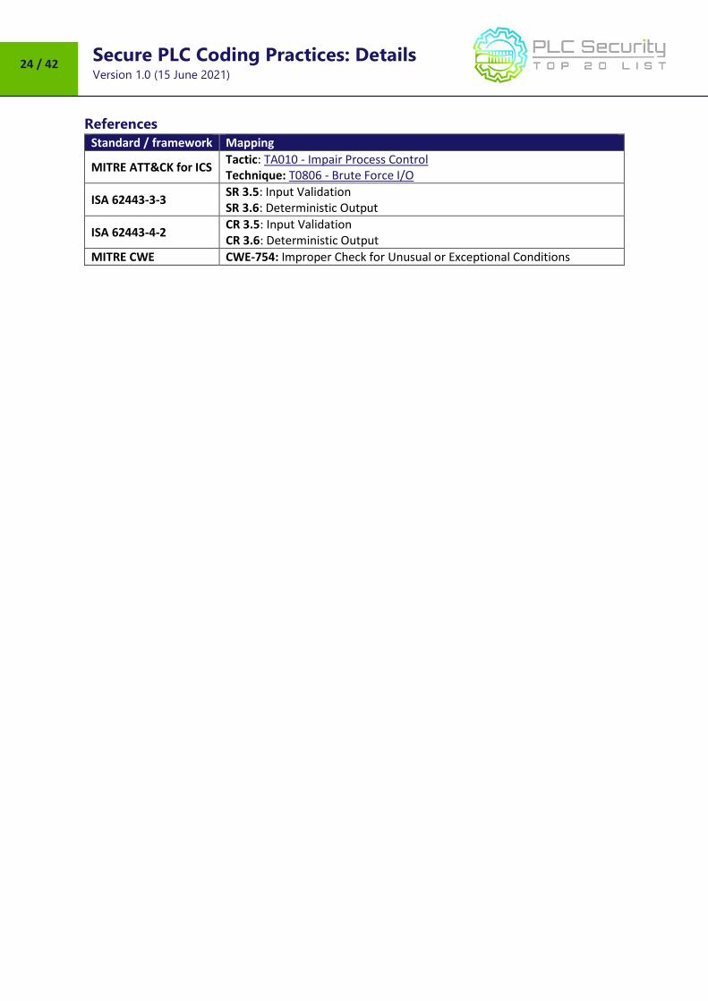
Standard / framework Mapping
MITRE ATT&CK for ICS Tactic: TA010 - Impair Process Control Technique: T0836 - Modify Parameter, T0806 - Brute Force I/O
ISA 62443-3-3 SR 3.5: Input Validation SR 3.6: Deterministic Output
ISA 62443-4-2 CR 3.5: Input Validation CR 3.6: Deterministic Output
ISA 62443-4-1 SI-2: Secure coding standards SVV-1: Security requirements testing
MITRE CWE CWE-754: Improper Check for Unusual or Exceptional Conditions
Secure PLC Coding Practices: Details Version 1.0 (15 June 2021)
15 / 42
8. Validate HMI input variables at the PLC level, not only at HMI
HMI access to PLC variables can (and should) be restricted to a valid operational value
range at the HMI, but further cross-checks in the PLC should be added to prevent, or
alert on, values outside of the acceptable ranges which are programmed into the HMI.
Security Objective Target Group
Integrity of PLC variables Product Supplier Integration / Maintenance Service Provider
Guidance
Input validation could include out-of-bounds checks for valid operational values as well as valid
values in terms of data types that are relative to the process.
If a PLC variable receives a value that is out-of-bounds, provide PLC logic to either
input a default value to that variable which does not negatively affect the process, and can
be used as a flag for alerts, or
input the last correct value to that value and log the event for further analysis.
Example
Example 1
An operation requires a user to input a value on an HMI for valve pressure. Valid ranges for this
operation are 0-100, and the user’s input is passed from the user input function on the HMI to the V1
variable in the PLC. In this case,
1. HMI input to variable V1 has a restricted range of 0-100 (dec.) programmed into the HMI.
2. The PLC has a cross-check logic that states:
IF V1 < 0 OR IF V1 > 100, SET V1 = 0.
This provides a positive response of a presumably safe value to an invalid input to that variable.
Example 2
An operation requires user input for measurement thresholds to a variable which should always be
within an INT2 data range. The user input is passed from the HMI into the V2 variable in the PLC,
which is a 16-bit data register.
1. HMI input to variable V2 has a restricted range of -32768 to 32767 (dec.) programmed into
the HMI.
2. The PLC has data-type cross-check logic that monitors the overflow variable (V3), which
exists just after V2 in the PLC’s memory structure:
IF V2 = -32768 OR IF V2 = 32767 AND V3 != 0,
SET V2 = 0 AND SET V3 = 0 AND SET DataTypeOverflowAlarm = TRUE.
Example 3
Scale PV (Process Value), SP (Set Point) and CV (Control Variable) for PID (Proportional, Integral,
Derivative controller) to consistent or raw units to eliminate scaling errors causing control problem.
Incorrect scaling might lead to inadvertent abuse cases.
Secure PLC Coding Practices: Details Version 1.0 (15 June 2021)
16 / 42
Why?
Beneficial for…? Why?
Security
1. While HMIs typically provide some sort of input validation, a malicious actor can craft or replay modified packets to send arbitrary values to the variables in the PLC which are open to outside influence (open to values passed from an HMI, for example).
2. PLC protocols are typically marketed as “open” protocols and published to the general public, so creating malware that utilizes “open” protocol information can be trivial to develop. PLC variable mapping can typically occur through traffic analysis during the reconnaissance phases of an attack, thus providing the intruder with the necessary information to craft malicious traffic to the target and thereby manipulate a process with unauthorized tools. Cross-checking values passed into the PLC before implementing that data into the process ensures valid data ranges and mitigates an invalid value in those memory locations by forcibly setting safe ranges when a value is detected as out-of-bounds during the course of the PLC scan.
Reliability /
Maintenance /
References
Standard / framework Mapping
MITRE ATT&CK for ICS Tactic: TA010 - Impair Process Control Technique: T0836 - Modify Parameter
ISA 62443-3-3 SR 3.5: Input Validation SR 3.6: Deterministic Output
ISA 62443-4-2 CR 3.5: Input Validation CR 3.6: Deterministic Output
ISA 62443-4-1 SI-2: Secure coding standards SVV-1: Security requirements testing
MITRE CWE CWE-1320: Improper Protection for Out of Bounds Signal Level Alerts
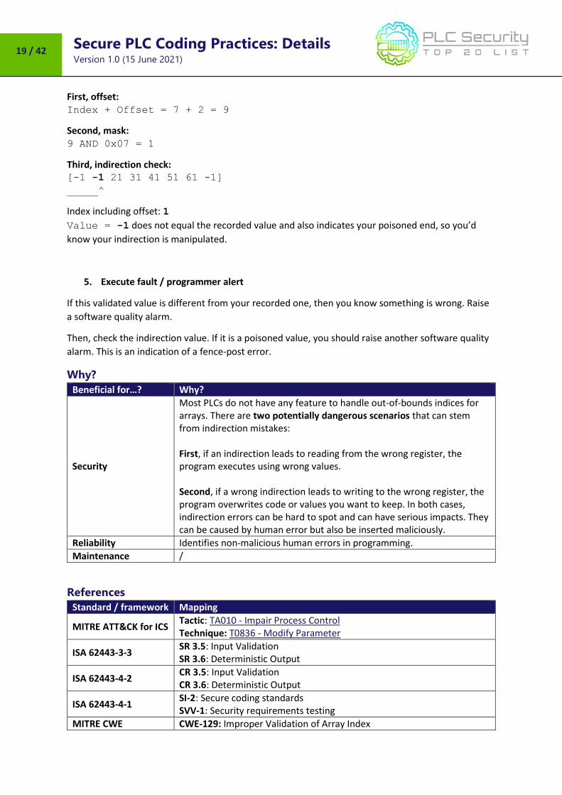
Value = -1 does not equal the recorded value and also indicates your poisoned end, so you’d
know your indirection is manipulated.
5. Execute fault / programmer alert
If this validated value is different from your recorded one, then you know something is wrong. Raise
a software quality alarm.
Then, check the indirection value. If it is a poisoned value, you should raise another software quality
alarm. This is an indication of a fence-post error.
Why?
Beneficial for…? Why?
Security
Most PLCs do not have any feature to handle out-of-bounds indices for arrays. There are two potentially dangerous scenarios that can stem from indirection mistakes: First, if an indirection leads to reading from the wrong register, the program executes using wrong values. Second, if a wrong indirection leads to writing to the wrong register, the program overwrites code or values you want to keep. In both cases, indirection errors can be hard to spot and can have serious impacts. They can be caused by human error but also be inserted maliciously.
Reliability Identifies non-malicious human errors in programming.
Maintenance /
References
Standard / framework Mapping
MITRE ATT&CK for ICS Tactic: TA010 - Impair Process Control Technique: T0836 - Modify Parameter
ISA 62443-3-3 SR 3.5: Input Validation SR 3.6: Deterministic Output
ISA 62443-4-2 CR 3.5: Input Validation CR 3.6: Deterministic Output
ISA 62443-4-1 SI-2: Secure coding standards SVV-1: Security requirements testing
MITRE CWE CWE-129: Improper Validation of Array Index
Secure PLC Coding Practices: Details Version 1.0 (15 June 2021)
20 / 42
10. Assign designated register blocks by function
(read/write/validate)
Assign designated register blocks for specific functions in order to validate data, avoid
buffer overflows and block unauthorized external writes to protect controller data.
Security Objective Target Group
Integrity of PLC variables Product Supplier Integration / Maintenance Service Provider
Guidance
Temporary memory, also known as scratch pad memory, is an easily exploitable area of memory if
this practice is not followed. e.g., simply writing to a “Modbus” register that is out of bounds could
lead to overwriting memory registers used for temporary calculations.
Generally, register memory can be accessed by other devices across the PLC network for read and
write operations. Some registers could be read by an HMI, and others could be written by a SCADA
system etc. Having specific register arrays for a certain application also makes it easier (in the
controller or an external firewall is used) to configure Read only access from another device/HMI.
Examples of functions for which designated register blocks make sense are:
reading
writing (from HMI / Controller / other external device)
validating writes
calculations Ensuring external writes to allowable registers also helps in avoiding main memory reset errors either
due to out of bound execution or malicious attempts. These designated register blocks can be used
as buffers for I/O, timer, and counter writes by validating that the buffer is completely written (does
not contain part old, part new data) and validating all the data in the buffer.
Background:
Main memory and register memory are used differently. Main memory is used for storing currently
executing program logic whereas the register memory is used as a temporary memory by the
currently executing logic. Though register memory is a temporary one, since it is being used by the
executing logic it is bound to contain some important variables that would affect the main logic.
Example
Examples for what could happen if this practice is not implemented:
(Reference: G. P. H. Sandaruwan, P. S. Ranaweera, Vladimir A. Oleshchuk, PLC Security and Critical
Infrastructure Protection):
Siemens typically uses the scratchpad memory in the flag area from flag 200.0 to flag 255.7.
If a bit is changed within this area there is a likelihood of a serious malfunction of the PLC
based on the importance of that bit or byte.
Assume that an attacker can gain access to one of the machines in the PLC network and
infect that machine with a worm which is capable of writing arbitrary values to the register
Secure PLC Coding Practices: Details Version 1.0 (15 June 2021)
21 / 42
memory. Since the register memory values changed arbitrarily, it can change the pressure
value.
Executing logic will set a new value based on the change and that may cause the system to
exceed its safety margins and possibly driven to a failure.
Examples for implementing this practice:
In a scenario where there is a safety zone (but the DCS can read), the firewall can log any
"write’ attempts with a rule that these registers are READ ONLY in the safety zone.
In another scenario, there could be some write-capable registers, and others are read only,
but having all the READ ONLY registers in a single array makes it easier to configure them in
the controller (or a firewall).
Why?
Beneficial for…? Why?
Security
Makes it easier to protect the controller data by function (read/write/validate). Makes it easier for protocol sensitive firewalls to do their job: The rules get simpler because it is very clear what register blocks are allowed for the HMI to access. Makes it easier to manage the (simpler) rules in the firewall. Making unauthorized changes to internal temporary memory is an easily exploitable vulnerability (By-pass Logic Attack). When inputs and outputs to PLC routines are properly validated, any changes (by a malicious actor or by mistake) can be caught easily instead of staying in the logic sequence for long and throwing errors / causing issues later in execution.
Reliability
Makes reads and writes go faster because the number of transactions is reduced. Even authorized changes and programming mistakes can cause a malfunction if temporary memory is not protected. Network and communications errors on long messages can result in unintended errors if the validity of the data is not checked prior to processing.
Maintenance Programming mistakes causing writing to temporary memory can make it hard to find errors, so the problem can be avoided by assigning specific registers for writes.
Secure PLC Coding Practices: Details Version 1.0 (15 June 2021)
22 / 42
References
Standard / framework Mapping
MITRE ATT&CK for ICS Tactic : TA009 - Inhibit Response Function, TA010 - Impair Process Control Technique: T0835 - Manipulate I/O image , T0836 - Modify Parameter
ISA 62443-3-3 SR 3.4 : Software and information integrity SR 3.5 : Input Validation SR 3.6 : Deterministic Output
Secure PLC Coding Practices: Details Version 1.0 (15 June 2021)
25 / 42
12. Validate inputs based on physical plausibility
Ensure operators can only input what’s practical or physically feasible in the process.
Set a timer for an operation to the duration it should physically take. Consider alerting
when there are deviations. Also alert when there is unexpected inactivity.
Security Objective Target Group
Integrity of I/O values Integration / Maintenance Service Provider
Guidance
a) Monitor expected physical durations
If the operation takes longer than expected to go from one extreme to the other, that is worthy of an
alarm. Alternatively, if it does it too quickly, that is worthy of an alarm too.
A simple solution could be a step-timeout alert. This would be useful for sequence/step-controlled
tasks.
For example, the step “move object from A to B” takes 5 sec from start of the step until the transition
condition (sensor: object arrived at B) is met.
If the condition is met significantly too early or too late, the step-timeout is alert triggered.
b) Monitor expected physical repeating activity
Physical plausibility checking can also mean alert for physically implausible inactivity: If there is an
expectation of a regular, repeating cycle of events (e.g., batches, diurnal patterns), an inactivity timer
would alert if something which is expected to change (discrete or analog value) remains static for far
too long.
Example
a) Monitor expected physical durations
The gates on a dam takes a certain time to go from fully closed to fully open
In a wastewater utility, a wet well takes a certain time to fill
b) Monitor expected physical repeating activity
Manufacturing process or pipeline batching should regularly cycle between control ranges or
operating modes.
Municipal wastewater treatment plants typically have a diurnal cycle of activity / pattern of
influent flow rates.
c) Limit operator entry for set points to what’s practical/physically possible.
e.g., Oldsmar Florida case allowed for operator input that’s a) thousands of times more
than what was typically needed b) that’s physically not possible. Try to configure the
operational limits in the PLC code wherever possible instead of using HMI scripts.
Secure PLC Coding Practices: Details Version 1.0 (15 June 2021)
26 / 42
Why?
Beneficial for…? Why?
Security
1. Deviations can indicate an actuator was already in the middle of a travel state or that someone is trying to fake the I/O, e.g., by doing a replay attack.
2. Inactivity alerts facilitate monitoring for frozen or forced constant values which could be the result of system or device tampering.
Reliability
1. Deviations give you an early alert for broken equipment due electrical or mechanical failures.
2. Inactivity alerts help flag measurements or system control loops which may be failing (thus static) due to physical device fault or an issue with the logic control algorithm or failed/improper operator input.
Maintenance
References
Standard / framework Mapping
MITRE ATT&CK for ICS Tactic: TA010 - Impair Process Control Technique: T0806 - Brute Force I/O
ISA 62443-3-3 SR 3.5: Input Validation SR 3.6: Deterministic Output
ISA 62443-4-2 CR 3.5: Input Validation CR 3.6: Deterministic Output
MITRE CWE CWE-754: Improper Check for Unusual or Exceptional Conditions
Secure PLC Coding Practices: Details Version 1.0 (15 June 2021)
27 / 42
13. Disable unneeded / unused communication ports and protocols
PLC controllers and network interface modules generally support multiple
communication protocols that are enabled by default. Disable ports and protocols that
are not required for the application.
Security Objective Target Group
Hardening Integration / Maintenance Service Provider
Guidance
Common protocols usually enabled by default are e.g., HTTP, HTTPS, SNMP, Telnet, FTP, MODBUS,
PROFIBUS, EtherNet/IP, ICMP, etc.
Best practice is to develop a data flow diagram that depicts the required communications between
the PLC and other components in the system.
The data flow diagram should show both the physical ports on the PLC as well as the logical networks
they are connected to. For each physical port, a list of required network protocols should be
identified and all others disabled.
Example
For example, many PLCs include an embedded web server for maintenance and troubleshooting. If
this feature will not be used, if possible, it should be disabled as this could be an attack vector.
Why?
Beneficial for…? Why?
Security Every enabled port and protocol add to the PLC’s potential attack surface. The easiest way to make sure an attacker can’t use them for unauthorized communication is to disable them altogether.
Reliability
If a PLC cannot communicate via a certain port or protocol, this also reduces the potential amount of (malformed) traffic, be it malicious or not, which decreases the chances of the PLC crashing because of unintended / malformed communication packages.
Maintenance Disabling unused ports and protocols also facilitates maintenance, because it reduces the PLC’s overall complexity. What’s not there does not need to be administrated or updated.
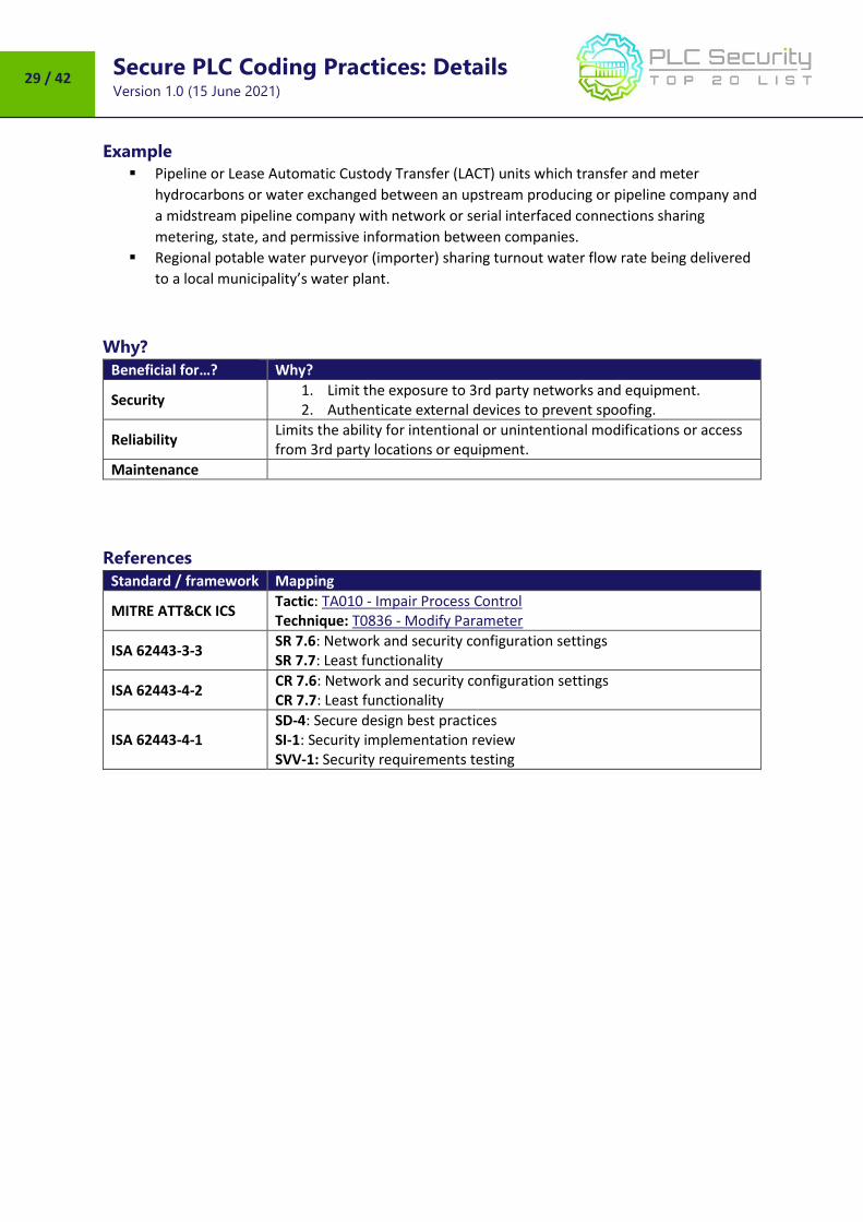
References
Standard / framework Mapping
MITRE ATT&CK for ICS Tactic: TA005 - Discovery Technique: T0808 - Control Device Identification , T0841 - Network Service Scanning, T0854 - Serial Connection Enumeration
ISA 62443-3-3 SR 7.6: Network and security configuration settings SR 7.7: Least functionality
ISA 62443-4-2 EDR 2.13 : Use of physical diagnostic and test interfaces
ISA 62443-4-1 SD-4: Secure design best practices SI-1: Security implementation review SVV-1: Security requirements testing
Secure PLC Coding Practices: Details Version 1.0 (15 June 2021)
30 / 42
15. Define a safe process state in case of a PLC restart
Define safe states for the process in case of PLC restarts (e.g., energize contacts, de-
energize, keep previous state).
Security Objective Target Group
Resilience Product Supplier Integration / Maintenance Service Provider
Guidance
If something commands a PLC to restart in the middle of a working process, we should expect the
program to pick up smoothly with minimal disruption to the process. Make sure that the process it
controls is restart-safe.
If it is not practical to configure the PLC to restart-safely, be sure that it alerts you to this fact and
that it does not issue any new commands. Also, for that case, ensure that the Standard Operating
Procedures (SOP) have very clear instructions for setting the manual controls so that the PLC will
start up the process properly.
Also, document all start-up, shut-down, steady state control, and flying control system restart
procedures.
Example
/
Why?
Beneficial for…? Why?
Security
Eliminates potential unexpected behavior: The most basic attack vector for a PLC is to force it to crash and / or restart. For many PLCs, it is not that hard to do, because many PLCs cannot cope well with unexpected inputs or too much traffic. While there are several diagnostics for controller actions while it is running, how it handles startup up with a running process is usually not clear. This may be uncommon, but it is a basic attack vector if we take into account malicious behavior of an attacker.
Reliability
Avoid unexpected delays: If after a PLC power on, the state machine initializes to a state with some conditions that don’t let the process to start, and the operator cannot normalize the system, a technician would need to enter the PLC program to force the conditions to go to the desired state to be able to start operation. This could cause delays and production losses.
Maintenance /
Secure PLC Coding Practices: Details Version 1.0 (15 June 2021)
Secure PLC Coding Practices: Details Version 1.0 (15 June 2021)
32 / 42
16. Summarize PLC cycle times and trend them on the HMI
Summarize PLC cycle time every 2-3 seconds and report to HMI for visualization on a
graph.
Security Objective Target Group
Monitoring Integration / Maintenance Service Provider
Guidance
Cycle times are usually system variables in a PLC and can be used for summarizing in PLC code.
Summarization should be done to calculate average, peak, and minimum cycle times. The HMI should
trend these values and alert if there are significant changes.
The cycle time is the time it takes to compute each iteration of logic for the PLC. The iterations are
the combination of Ladder Diagrams (LD), Function Block Diagrams (FBD), Instruction List (IL), and
Structured Text (ST). These logic components may be joined together with the Sequential Function
Charts (SFC).
Cycle times should be constant on a PLC unless there are changes to e.g.
network environment
PLC logic
process
Therefore, unusual cycle time changes can be an indicator that PLC logic changed and thus provide
valuable information for integrity checks.
Visualizing values over time using a graph provides an intuitive way to draw attention to anomalies
which would be harder to notice by just having absolute values.
Example
Many PLCs have a “maximum cycle time” monitoring at hardware level. If the cycle time exceeds the
maximum value, the hardware sets the CPU to STOP (5).
Of course, attackers are aware of this and will keep a possible attack code as lean as possible to
minimize the impact on the overall cycle time. In an additional software cycle time monitoring
program, a reference cylce time tref is defined as base cycle time. As small fluctuations are natural,
an acceptable threshold needs to be defined (1,3) The cycle monitoring is triggered, if the threshold
is exceeded (2,4).
Secure PLC Coding Practices: Details Version 1.0 (15 June 2021)
33 / 42
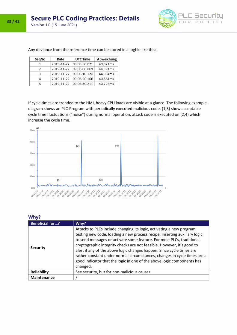
Any deviance from the reference time can be stored in a logfile like this:
If cycle times are trended to the HMI, heavy CPU loads are visible at a glance. The following example
diagram shows an PLC-Program with periodically executed malicious code. (1,3) show acceptable
cycle time fluctuations (“noise”) during normal operation, attack code is executed on (2,4) which
increase the cycle time.
Why?
Beneficial for…? Why?
Security
Attacks to PLCs include changing its logic, activating a new program, testing new code, loading a new process recipe, inserting auxiliary logic to send messages or activate some feature. For most PLCs, traditional cryptographic integrity checks are not feasible. However, it’s good to alert if any of the above logic changes happen. Since cycle times are rather constant under normal circumstances, changes in cycle times are a good indicator that the logic in one of the above logic components has changed.
Reliability See security, but for non-malicious causes.
Maintenance /
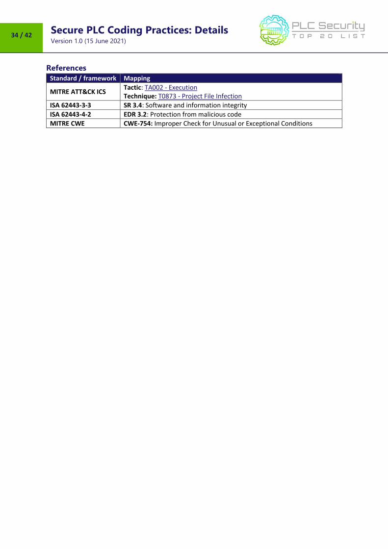
Secure PLC Coding Practices: Details Version 1.0 (15 June 2021)
Secure PLC Coding Practices: Details Version 1.0 (15 June 2021)
35 / 42
17. Log PLC uptime and trend it on the HMI
Log PLC uptime to know when it’s been restarted. Trend and log uptime on the HMI for
diagnostics.
Security Objective Target Group
Monitoring Integration / Maintenance Service Provider
Guidance
Keep track of PLC uptime
in the PLC itself (if uptime is a system variable in the PLC)
in the PLC itself if it has MIB-2 / any SNMP implementation
externally by means of e.g., SNMP
If the PLC has SNMP with MIB-2, which is very common, the OID for uptime “sysUpTimeInstance(0)”
is 1.3.6.1.2.1.1.3. Uptime resets are important indicators for PLC restarts. Make sure the HMI
alerts to any sort of PLC restart.
Uptime correlated with error codes are good diagnostics.
Example
/
Why?
Beneficial for…? Why?
Security
The most basic attack vector for a PLC is to force it to crash and / or restart. For many PLCs, it is not that hard to do, because many PLCs cannot cope well with unexpected inputs or too much traffic. Thus, unexpected restarts can be an indicator that the PLC encounters unusual actions.
Reliability PLC restarts are also good for diagnostics in case of failures and for monitoring which PLCs are being worked on at what time.
Secure PLC Coding Practices: Details Version 1.0 (15 June 2021)
36 / 42
18. Log PLC hard stops and trend them on the HMI
Store PLC hard stop events from faults or shutdowns for retrieval by HMI alarm
systems to consult before PLC restarts. Time sync for more accurate data.
Security Objective Target Group
Monitoring Integration / Maintenance Service Provider
Guidance
Fault events indicate why a PLC shut down so that the issue can be addressed before a restart.
Some PLCs may have error codes from the last case where the PLC faulted or shut down improperly.
Record those errors and then clear them. It might be a good idea to report those errors to the HMI as
informational data or perhaps to a syslog server, if those features and that infrastructure exist.
Most PLCs also have some kind of first scan feature that generates events. It is a behavior that nearly
all PLC equipment have in some form. It is basically one or more flags, or a designated routine that is
executed on the first scan of a PLC after it “wakes up.” This First Scan should be logged and tracked.
Example
/
Why?
Beneficial for…? Why?
Security Logs enable troubleshooting in case of an incident. Before a PLC becomes operational, especially after having experienced problems, it is important to ensure it is trustworthy.
Reliability Logs are also good sources for debugging if the event was not caused maliciously.
Secure PLC Coding Practices: Details Version 1.0 (15 June 2021)
37 / 42
19. Monitor PLC memory usage and trend it on the HMI
Measure and provide a baseline for memory usage for every controller deployed in the
production environment and trend it on the HMI.
Security Objective Target Group
Monitoring Integration / Maintenance Service Provider Asset Owner
Guidance
Since the increase of lines of code in the logic can also lead to increased memory consumption at
runtime, it is recommended for PLC programmers to track any deviation from the baseline and
dedicate an alarm class to this event.
Example
In Rockwell Allen Bradley PLCs, a baseline can be established on a controller and memory usage can
be tracked using the RSLogix 5000 Task Monitor Tool. Not only the main memory but also the I/O
memory and Ladder/Tag memory can be tracked using trends.
Why?
Beneficial for…? Why?
Security Increased memory usage can be an indicator of the PLC running altered code.
Reliability Tracking memory usage for the running programs could be useful in avoiding total memory consumption and eventual fault state for the PLC controller.
Maintenance Tracking memory usage could be used in tuning and finding the best scan time for the monitored controller but also in troubleshooting problems and issues related to faulty states.
Secure PLC Coding Practices: Details Version 1.0 (15 June 2021)
38 / 42
20. Trap false negatives and false positives for critical alerts
Identify critical alerts and program a trap for those alerts. Set the trap to monitor the
trigger conditions and the alert state for any deviation.
Security Objective Target Group
Monitoring Integration / Maintenance Service Provider
Guidance
In most cases, alert-states are boolean (True, False) and triggered by certain conditions as displayed
below. E.g., the trigger bit for the alert ‘overpressure’ becomes TRUE, if Condition 1 ‘pressure switch
1’, Condition 2 ‘pressure sensor value over critical threshold’, through n., are TRUE.
To masquerade an attack, an adversary could suppress the alert trigger bit and cause a false
negative.
A trap for false negatives monitors the conditions for the trigger bit and the negated trigger bit itself.
With this simple setup, a false negative is detected. See the following picture:
In other cases, an adversary could deliberately cause false positives, to wear down the process
operator’s attention.
In the same manner of the false negative trap, false positives can also be detected by monitoring the
alert trigger bit and if the trigger conditions are met. If the conditions are NOT met, but the trigger bit
is active, a false positive is detected: See the following picture:
Secure PLC Coding Practices: Details Version 1.0 (15 June 2021)
39 / 42
Example
Example 1: Siemens offers in their Siemens S7-1200/1500 Products a Webserver with a wide range of
functions, for example display of the PLC-State, cycle time or scope records. It also has the option to
view and modify data tables and variables. The access rights to the Webserver can be modified in the
PLC-Hardware Settings. In case of mis-configured access rights an adversary could gain access to the
PLC Variables and Datablocks. To create a false positive, the adversary selects an alert trigger bit and
alters the state.
Example 2: In the Triton/Trisys/HatMan attack, rogue code suppressed alert states.
Example 3: A bus-injection attack could send a false positive alert to a high-level SCADA client.
Why?
Beneficial for…? Why?
Security
Mitigates false negative or false positives of critical alert messages caused by an adversary obfuscating their attack (i.e., rogue code, bus injection, tampering with accessible PLC state tables on unsecured webservers).