Secure Position and Time Information by Server Side PRS Snapshot Processing Alexander R¨ ugamer, Daniel Rubino, Ivana Lukˇ cin, Simon Taschke, Manuel Stahl, Wolfgang Felber Fraunhofer Institute for Integrated Circuits IIS, Nuremberg, Germany BIOGRAPHY Alexander R¨ ugamer received his Dipl.-Ing. (FH) degree in Electrical Engineering from the University of Applied Sci- ences Wuerzburg-Schweinfurt, Germany, in 2007. Since then he has been working at the Fraunhofer Institute for In- tegrated Circuits IIS in the Field of GNSS receiver devel- opment. He was promoted to Senior Engineer in February 2012. Since April 2013, he is head of a research group deal- ing with secure GNSS receivers and receivers for special applications. His main research interests focus on GNSS multi-band reception, integrated circuits and immunity to interference. Daniel Rubino received his MSc. degree in Industrial En- gineering and Management from the University Erlangen- Nuremberg, Germany, in 2015. Upon graduation he joined the Fraunhofer Institute for Integrated Circuits IIS, where he is involved in signal processing for GNSS receiver in- cluding software and hardware development. Ivana Lukˇ cin received her MSc. degree in Mathematics from the University of Zagreb, Croatia, in 2012. Since then, she has been working at the Fraunhofer Institute for Integrated Circuits IIS in the field of compressed sensing and snapshot positioning. Simon Taschke received his Msc. degree in Geodesy and Geoinformatics from the University of Stuttgart, Germany, in 2015. Since the same year he has been working at the Fraunhofer Institute for Integrated Circuits IIS in the field of GNSS receiver development and testing. Manuel Stahl received his Dipl.-Inf. degree in Computer Sciences from the University of Wuerzburg, Germany, in 2009. Since the same year he has been working at the Fraunhofer Institute for Integrated Circuits IIS in the field of GNSS receiver software development for embedded sys- tems and mobile robotics. Wolfgang Felber received his Dipl.-Ing. degree in electri- cal engineering in 2002 and his doctoral degree Dr.-Ing. in 2006 from Helmut-Schmidt-University of Federal Armed Forces Hamburg, Germany. Since 2014 he is head of the Power Efficient Systems department of Fraunhofer IIS in Nuremberg. The main topics in his department are energy harvesting and low power technologies, hardware develop- ment of satellite navigation receivers and sensor fusion in positioning applications. ABSTRACT An alternative way to benefit from spoofing-resistant Galileo Public Regulated Service (PRS) signals is to use a server side processing concept, where all security-related process- ing steps are outsourced. Having outlined the architec- ture with user terminal, communication channel and re- mote server, the snapshot positioning algorithms with dif- ferent pseudorange reconstruction methods are presented. To reduce the snapshot size, data compression methods are possible, however, degrading the effective C/N 0 . The re- sults are demonstrated, processing E1 Pseudo-PRS signals from an RF constellation simulator and applying differ- ent compression techniques. Multiple raw data snapshots, with sizes from 810 to 10 kByte are evaluated providing Galileo E1 PRS snapshot positioning 1σ accuracy from 1.1 to 6.0 m. Finally, a method to estimate the accuracy from a single snapshot result is outlined. INTRODUCTION Galileo Public Regulated Service (PRS) is a special, cryp- tographically protected satellite navigation service intended for government authorized users. The access to PRS is regulated by decision No 1104/2011/EU of the European Parliament and of the Council and controlled by member states. With the encryption used in Galileo PRS, the manipula- tion of a PRS-obtained time and position is hardly possible. This allows the realization of many demanding or security critical applications that could not be operated using con- ventional GPS or Galileo Global Navigation Satellite Ser- vices (GNSS). However, PRS receivers won’t be available to ordinary users. Moreover, in general, PRS receivers will never be as in- expensive as standard open service (OS) receivers and are Proceedings of the 29th International Technical Meeting of the ION Satellite Division, ION GNSS+ 2016, Portland, Oregon, September 12-16, 2016 3002
Transcript
Secure Position and Time Information byServer Side PRS Snapshot Processing
Alexander Rugamer, Daniel Rubino, Ivana Lukcin, Simon Taschke, Manuel Stahl, Wolfgang FelberFraunhofer Institute for Integrated Circuits IIS, Nuremberg, Germany
BIOGRAPHY
Alexander Rugamer received his Dipl.-Ing. (FH) degree inElectrical Engineering from the University of Applied Sci-ences Wuerzburg-Schweinfurt, Germany, in 2007. Sincethen he has been working at the Fraunhofer Institute for In-tegrated Circuits IIS in the Field of GNSS receiver devel-opment. He was promoted to Senior Engineer in February2012. Since April 2013, he is head of a research group deal-ing with secure GNSS receivers and receivers for specialapplications. His main research interests focus on GNSSmulti-band reception, integrated circuits and immunity tointerference.
Daniel Rubino received his MSc. degree in Industrial En-gineering and Management from the University Erlangen-Nuremberg, Germany, in 2015. Upon graduation he joinedthe Fraunhofer Institute for Integrated Circuits IIS, wherehe is involved in signal processing for GNSS receiver in-cluding software and hardware development.
Ivana Lukcin received her MSc. degree in Mathematicsfrom the University of Zagreb, Croatia, in 2012. Sincethen, she has been working at the Fraunhofer Institute forIntegrated Circuits IIS in the field of compressed sensingand snapshot positioning.
Simon Taschke received his Msc. degree in Geodesy andGeoinformatics from the University of Stuttgart, Germany,in 2015. Since the same year he has been working at theFraunhofer Institute for Integrated Circuits IIS in the fieldof GNSS receiver development and testing.
Manuel Stahl received his Dipl.-Inf. degree in ComputerSciences from the University of Wuerzburg, Germany, in2009. Since the same year he has been working at theFraunhofer Institute for Integrated Circuits IIS in the fieldof GNSS receiver software development for embedded sys-tems and mobile robotics.
Wolfgang Felber received his Dipl.-Ing. degree in electri-cal engineering in 2002 and his doctoral degree Dr.-Ing. in2006 from Helmut-Schmidt-University of Federal ArmedForces Hamburg, Germany. Since 2014 he is head of thePower Efficient Systems department of Fraunhofer IIS in
Nuremberg. The main topics in his department are energyharvesting and low power technologies, hardware develop-ment of satellite navigation receivers and sensor fusion inpositioning applications.
ABSTRACT
An alternative way to benefit from spoofing-resistant GalileoPublic Regulated Service (PRS) signals is to use a serverside processing concept, where all security-related process-ing steps are outsourced. Having outlined the architec-ture with user terminal, communication channel and re-mote server, the snapshot positioning algorithms with dif-ferent pseudorange reconstruction methods are presented.To reduce the snapshot size, data compression methods arepossible, however, degrading the effective C/N0. The re-sults are demonstrated, processing E1 Pseudo-PRS signalsfrom an RF constellation simulator and applying differ-ent compression techniques. Multiple raw data snapshots,with sizes from 810 to 10 kByte are evaluated providingGalileo E1 PRS snapshot positioning 1σ accuracy from1.1 to 6.0 m. Finally, a method to estimate the accuracyfrom a single snapshot result is outlined.
INTRODUCTION
Galileo Public Regulated Service (PRS) is a special, cryp-tographically protected satellite navigation service intendedfor government authorized users. The access to PRS isregulated by decision No 1104/2011/EU of the EuropeanParliament and of the Council and controlled by memberstates.
With the encryption used in Galileo PRS, the manipula-tion of a PRS-obtained time and position is hardly possible.This allows the realization of many demanding or securitycritical applications that could not be operated using con-ventional GPS or Galileo Global Navigation Satellite Ser-vices (GNSS).
However, PRS receivers won’t be available to ordinary users.Moreover, in general, PRS receivers will never be as in-expensive as standard open service (OS) receivers and are
Proceedings of the 29th International Technical Meeting of the ION SatelliteDivision, ION GNSS+ 2016, Portland, Oregon, September 12-16, 2016
3002
more complex in their handling due to their security mod-ule and the necessary key management.
An alternative to these conventional PRS receivers are server-based or remote processing PRS receivers [1]: The generalidea is to outsource the PRS signal processing to a secureserver environment. The user terminal itself samples onlyraw data signals and forwards them to the server, where thePRS information included in the raw samples is processed.
The PRS is only used in a passive, non-real-time way by theuser. The remote PRS server service provider decides if andwhich information is returned to the user. This leads to cer-tain advantages over conventional Galileo PRS receivers:Firstly, users do not have to care about the security require-ments of PRS since there are no PRS security-related func-tions on the user receiver side. Secondly, the Galileo PRSsecurity cannot in any way be endangered by the user, sincethe user terminal does not contain any PRS relevant meth-ods or information (e.g. a security module).
Having outlined the Galileo signals, the architecture of aserver side PRS processing concept with user terminals isdescribed. Then we discuss methods to obtain a positionand time information out of raw snapshot data. We start bydescribing the state of the art of snapshot processing withits requirements and limitations. After that, we introduce anew snapshot position technique that directly resolves theacquisition code phase ambiguity by exploiting pilot sig-nals’ secondary code resulting in unambiguous measure-ments. Finally, we show how the snapshot techniques canbe applied to Galileo PRS signals. The snapshot size gener-ated by the user terminal is crucial for most remote process-ing applications. Therefore, data compression methods andtheir impacts on the probability of detection and accuracyestimation are explained. The experimental setup to recordand evaluate GNSS RF simulator E1 Pseudo-PRS signalsis outlined and the snapshot processing results using differ-ent compression setups are presented. Having discussed amethod with proof of concept results to estimate the accu-racy from a single snapshot, the paper concludes with theoutline of possible applications for server-side PRS snap-shot positioning.
GALILEO PRS
The European GNSS Galileo provides three different globalnavigation services: Open Service (OS), Commercial Ser-vice (CS), and the Public Regulated Service (PRS). GalileoOS is similar to the free services of GPS and GLONASS.The Galileo CS is not yet fully defined. Galileo PRS fea-tures two encrypted signals on two frequency bands andtargets government authorized users, e.g. police, bordercontrol, emergency, armed forces, Search and Rescue, andalso operators of critical infrastructures like telecommuni-cation and energy networks as well as critical transports.
As shown in Fig. 1, the Galileo PRS signals are transmit-
ted in a coherent way together with the OS and CS sig-nals over the E1A and E6A frequency bands, using a binaryoffset carrier (BOC) modulation denoted as BOCc(15,2.5)and BOCc(10,5), respectively. BOCc uses a cosine phasedsubcarrier resulting in higher frequency components thana sine phased subcarrier used in BOCs modulations of e.g.Galileo E1BC OS. As a result, more energy is shifted to theedges of the band. This improves the spectral separationwith the coexisting OS and CS signals and the theoreticaltracking performance [2].
Thanks to the encryption used, Galileo PRS can add a le-gal value on its PRS position, velocity and time (PVT) so-lution since anti-spoofing is guaranteed. This property isa key opener to many critical and demanding applicationsmostly in security-related areas. Although everyone can re-ceive the PRS raw data, only someone having the decryp-tion key is capable of generating the PRS pseudo-random-noise (PRN) sequences to despread the PRS signals and toprocess their messages.
GALILEO OS/PRS SNAPSHOT RECEIVER
Architecture
The concept of a PRS sample and processing snapshot re-ceiver is to outsource the actual acquisition and positioncalculation to a secure server environment. As illustratedin Fig. 2, the architecture consists of a number of user ter-minals and a PRS remote processing server. The autho-rized users can benefit from the PRS without jeopardizingGalileo PRS security. The PRS remote processing serveralone supports all the PRS security processing features,whereas inexpensive and miniaturized end user devices arefeasible as user terminals without an integrated PRS secu-rity module.
Antenna and Data Grabber
The user terminal receives OS/PRS signals from a PRSsuitable antenna on either E1A, E6A, or both frequencybands. Afterwards, a raw OS/PRS data snapshot is recordedusing a front-end also denoted as data grabber. The recordedraw data snapshot can be reduced in size according to theapplication requirements.
To be able to receive the BOCc modulated PRS signals,a reception bandwidth of approx. 40 MHz is required withrespect to the E1 and E6 center frequencies of 1575.42 MHzand 1278.75 MHz. Depending on the intended application,a single band reception of E1 or E6, or even the receptionof a single main lobe of the BOC signal only might be suffi-cient. However, it should be noted that the dual-band capa-bility of PRS provides a significantly higher jamming pro-tection: If one signal band is jammed, the other one mightstill be usable. Moreover, limiting the reception to a singlesideband of the BOC-modulated PRS signal will add someC/N0 reception power loss, as discussed in the ”Data Com-pression Effects” section.
3003
E1A - BOCcos(15,2.5)
Inph
ase
Quadratur-phase
1268,52 MHz10 MHz BW
1263,52...1273,52
1288,98 MHz10 MHz BW
1283,98...1293,98
1560,075 MHz5 MHz BW
1557,92...1562,92
1590,765 MHz5 MHz BW
1588,265...1593,265
E6A - BOCcos(10,5)
E6BCBPSK(5)
E1BCCBOC(6,1,1/11)
1278.75 MHz 1575.42 MHz1278.75 MHz
Figure 1. Galileo PRS signals
Communication link
User terminal
PRS antenna
Data-grabber
recording
PRS remote
processing server
PRN code
provider
Storage
medium
Snapshot size
reduction
Data exchange
Snapshot
algorithms
Combine
snapshot with
measurements
User
authenticationSnapshot + meta data
Position / verification
2
1
Snapshot
signature
Figure 2. System architecture with communication link (1) and data transfer link for postprocessing (2)
3004
Since for most applications the user terminal should besmall and inexpensive, the wideband signals on two fre-quency bands are a challenge. There are some geodeticGNSS antennas capable of receiving the dual-band BOCcmodulated PRS signals, however, they are by far neitherinexpensive nor small. Most mobile end user devices useintegrated antennas or chip antennas. These antennas nor-mally only feature the reception of the E1 frequency band,and are often limited to GPS L1 C/A only using narrow,integrated filters. In general, miniaturized antennas whichcan receive GPS L1 together with the G1 GLONASS sig-nals centered around 1602 MHz are suited to at least alsoreceive the upper Galileo PRS E1 sidelobe. Another down-side of these integrated antennas is their limited efficiencyand linear polarization only leading to additional C/N0 re-ception losses.
Similar restrictions hold for the data grabber. Commer-cial GPS RF front-end chips like the Maxim MAX2769 [3]can be tuned in the frequency range of E1 from 1550 MHzto 1610 MHz, but their overall reception bandwidth is lim-ited to approx. 18 MHz dual-sided bandwidth. This is notenough to receive the full BOCc E1A signal but can be suf-ficient to receive E1 OS together with either the upper orlower E1A sidelobe.
Snapshot Size Reduction
In general, the user terminals’ raw data snapshot size is de-termined by the complex sampling rate fs, quantization bitsQ, and snapshot length l with:
size = fs ·Q · l (1)
Data compression can be applied in terms of resamplingand filtering the received signals (to reduce the fs), reduc-ing the quantization Q or limiting the recording length l orsize in other ways.
For many applications, the trade-offs between snapshot-size, probability of detection (reliability), and accuracy iscrucial. The different data compression effects are dis-cussed in the respective section.
Combination of Snapshot with a Measurement / SnapshotSignature
The raw PRS snapshot can be used as a digital fingerprinton a measurement, file, or document to be authenticatedwith a time and/or georeference.
Depending on the intended application and the required se-curity level, the raw sample snapshot device should be en-capsulated together with the actual measurement device ina tamper-proof housing. Such protected units are alreadystandard for many devices like on-board units, electricitysmart meters, etc.
The goal is to cryptographically combine the raw PRS snap-shot with the measurement to be signed in a way that the
positioning and time information of this measurement canbe authenticated using PRS later on. One way of doing thiscombination is using a public/private key infrastructure. Itis assumed that the user terminal incorporates a private keyand has shared its public key with the customer. The pri-vate key is used to sign a hash value of both the raw PRSsnapshot and the measurement. The public key, hash val-ues, and the actual measurement with raw PRS snapshotare forwarded and stored on a server. The uniqueness ofthe hash functions signed with the user terminal’s privatekey ensures that the raw PRS snapshot is cryptographicallycombined with the measurement.
To verify the measurement with its raw PRS snapshot, a3rd party can generate the same hashes out of the provideddata and compare them to the transmitted hash sums. Theintegrity of the provided hash sums can be verified usingthe user’s device published public key. [1]
Communication Channel
Depending on the actual application, a uni-directional orbi-directional communication link might be used.
The easiest kind of uni-directional link is to store all snap-shots on a local storage volume inside the user terminal andto forward the raw data snapshots only to the PRS remoteprocessing server when convenient. In general, also mobilecommunication links can be used for it. The uni-directionalapproach does not provide real-time tracking functionalitybut still provides the possibility to check or prove that ageoreferenced action or time has taken place at a PRS guar-anteed location and time.
Using the bi-directional link to forward the PRS snapshotwith meta data to the PRS remote processing server, theserver can calculate a snapshot PVT using the raw samplesand send this information back to the user terminal. De-pending on the application, communication channel used,snapshot-length, assisted data and so on, a certain latencyhas to be taken into account.
It is crucial for all mobile communication links to reducethe snapshot size as far as possible, because bandwidth isgenerally limited and expensive. Therefore, the impact ofpossible compressions are discussed in section ”Data Com-pression Effects”. However, experiments with UniversalMobile Telecommunications System (UMTS) communica-tion link modules have shown that the actual mobile net-work login requires much more power than transmittingseveral hundred kBytes of raw data [4]. Therefore, an ex-cessive raw size reduction might not even be needed. Butagain, such statements very much depend on the actual ap-plication and technology used to realize the communicationlink.
OS/PRS Remote Processing Server
First, the server has to authenticate the user terminal to en-sure that only registered devices are allowed to use its re-
3005
mote OS/PRS processing service. Then, the server can usethe full OS/PRS processing capabilities in a secure envi-ronment to calculate the position, velocity and time (PVT)solution on basis of the PRS. In order to do so, the snap-shot algorithm block is connected to a PRN code provider.For PRS the PRN code provider is crucial, since it includesa PRS security modules with the protected and classifiedcryptographic algorithms to generate the PRS PRN streams.The actual snapshot positioning algorithms used are out-lined in the following section.
SNAPSHOT ALGORITHMS
A conventional receiver acquires and tracks the availableGlobal Navigation Satellite Systems (GNSS) signals andobtains all the necessary navigation data during its trackingphase. The snapshot remote processing server has to copewith only a few milliseconds of recorded data. Therefore,a conventional tracking approach is not possible.
Since the broadcasted ephemeris data and correction pa-rameters cannot be decoded from the short raw data snap-shot, a secondary channel has to be used as an external datasource.
For a OS based snapshot receiver, two further challengesexist: the ambiguities in the pseudoranges and the coarsetime error. Both challenges do not exist for a PRS snapshotreceiver, which has some other difficulty to resolve.
Pseudorange Reconstruction based on a priori Positionand Time
The pseudorange computation, which is based on signaltransmission and arrival time, becomes challenging, sincethe signal time of transmission broadcasted by the satelliteis not available. The receiver can only detect the code phasewithin the signal’s code period.
As an example, a Galileo OS signal has a symbol periodor spreading code duration τE1BC of 4 ms, which is about1200 km in the spatial domain. So the known fractional partof the pseudorange PE1BC is restricted to the last 1200 km.Since the traveling time of the signal from satellite to re-ceiver will be approximately 20 to 25 times higher thanthe spreading code duration, an ambiguity term needs to besolved.
Van Diggelen [5] proposes a pseudorange reconstructionalgorithm to resolve the code period integer ambiguity foreach satellite based on an a priori time of transmission tref(XSV (tref )) and user position XRX given within a cer-tain accuracy. With available ephemeris, one can computethe expected geometric range ρ and solve the common biasbref term by setting an arbitrarily chosen integer ambiguityNref for a reference satellite (SVref )
bref = Nref · τE1BC + PE1BC,SVref−
(ρ(XRX , XSVref(tref ))− δtclk,SVref
)− εSVref, (2)
where εSV is the satellite dependent range error and δtclk,SVthe satellite clock error. With the computed common biasbref for the reference satellite the ambiguity for every otheracquired satellite can be solved as
where NSV is rounded to the nearest code duration integer(i.e. 1 unit ms for GPS L1 C/A and 4 ms for Galileo E1 OS)as indicated by b·e.
If the a priori time of transmission and user position havebeen accurate enough, all the ambiguity terms are solvedcorrectly and the so called full pseudorange can be recon-structed. As stated for GPS L1 C/A signal in [5], accurateenough means that the time of transmission may possessan error margin of up to 1 min and user position of up to150 km.
Pilot Secondary Code Pseudorange Reconstruction
Instead of using the pseudorange ambiguity resolution tech-nique described before, we propose a different approachby using the GNSS pilot signals’ secondary code (whereavailable) to directly obtain an unambiguous pseudorangemeasurement.
Modern GNSS have pilot signals, like the Galileo E1C,E5aQ and E5bQ and GPS L5Q, using a secondary code ontop of their primary spreading code to generate a long, socalled tiered code. The overall code duration is the productof primary and secondary code lengths.
For the Galileo pilot signals E1C, E5aQ and E5bQ, theoverall tiered code period is 100 ms. A tiered code lengthof 100 ms can resolve distances of approx. 30.000 km in anunambiguous way which is enough for a direct measure-ment of the distance between satellite and receiver.
However, in the standard acquisition method, one only ac-quires a single primary code sequence to obtain the am-biguous pseudorange measurement. Therefore, one doesnot directly know at which point in the secondary code themeasurement was taken leading to ambiguity one more. Tosolve it we utilize a search method exploiting the fact thatthe secondary code sequences are a priori known.
The secondary code acquisition algorithm reconstructs boththe code phase offset and the secondary code. This enablesthe direct computation of full pseudorange. In the case ofthe secondary code acquisition, full pseudorange computa-tion is not based on the prediction of the user position. Oneadvantage of the procedure is that no matter what a prioriuser position was given, the position converges to the ac-tual, exact user position.
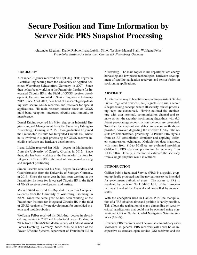
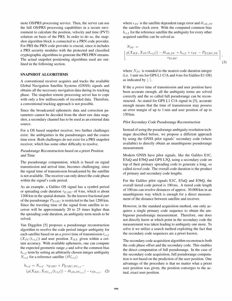
Figure 3 shows a secondary code reconstruction binary tree.In each step, two coherent correlations are done using twoconsecutive replica symbols: the first correlation is donewith both symbols having the same phase (e.g. [0 0]), thesecond correlation with symbols having the opposite phase(e.g. [0 1]). The two resulting correlation peaks are com-pared and the higher one (typical approx. twice as high)is identified as the correct estimation. The height of thisbinary search tree depends on the properties of the recon-structed secondary code. There is no need to go through allnodes. Instead, the decision for the right branch is made ineach step.
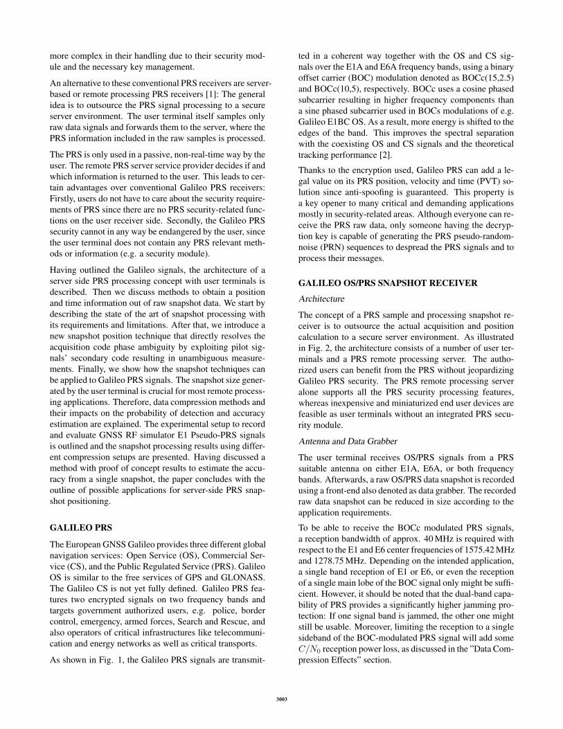
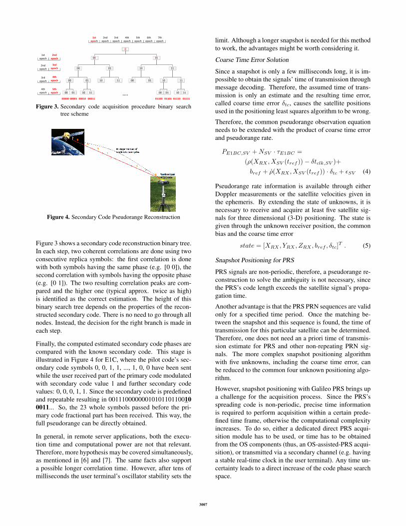
Finally, the computed estimated secondary code phases arecompared with the known secondary code. This stage isillustrated in Figure 4 for E1C, where the pilot code’s sec-ondary code symbols 0, 0, 1, 1, ..., 1, 0, 0 have been sentwhile the user received part of the primary code modulatedwith secondary code value 1 and further secondary codevalues: 0, 0, 0, 1, 1. Since the secondary code is predefinedand repeatable resulting in 00111000000010101101100100011... So, the 23 whole symbols passed before the pri-mary code fractional part has been received. This way, thefull pseudorange can be directly obtained.
In general, in remote server applications, both the execu-tion time and computational power are not that relevant.Therefore, more hypothesis may be covered simultaneously,as mentioned in [6] and [7]. The same facts also supporta possible longer correlation time. However, after tens ofmilliseconds the user terminal’s oscillator stability sets the
limit. Although a longer snapshot is needed for this methodto work, the advantages might be worth considering it.
Coarse Time Error Solution
Since a snapshot is only a few milliseconds long, it is im-possible to obtain the signals’ time of transmission throughmessage decoding. Therefore, the assumed time of trans-mission is only an estimate and the resulting time error,called coarse time error δtc, causes the satellite positionsused in the positioning least squares algorithm to be wrong.
Therefore, the common pseudorange observation equationneeds to be extended with the product of coarse time errorand pseudorange rate.
PE1BC,SV +NSV · τE1BC =
(ρ(XRX , XSV (tref ))− δtclk,SV )+
bref + ρ(XRX , XSV (tref )) · δtc + εSV (4)
Pseudorange rate information is available through eitherDoppler measurements or the satellite velocities given inthe ephemeris. By extending the state of unknowns, it isnecessary to receive and acquire at least five satellite sig-nals for three dimensional (3-D) positioning. The state isgiven through the unknown receiver position, the commonbias and the coarse time error
state = [XRX , YRX , ZRX , bref , δtc]T . (5)
Snapshot Positioning for PRS
PRS signals are non-periodic, therefore, a pseudorange re-construction to solve the ambiguity is not necessary, sincethe PRS’s code length exceeds the satellite signal’s propa-gation time.
Another advantage is that the PRS PRN sequences are validonly for a specified time period. Once the matching be-tween the snapshot and this sequence is found, the time oftransmission for this particular satellite can be determined.Therefore, one does not need an a priori time of transmis-sion estimate for PRS and other non-repeating PRN sig-nals. The more complex snapshot positioning algorithmwith five unknowns, including the coarse time error, canbe reduced to the common four unknown positioning algo-rithm.
However, snapshot positioning with Galileo PRS brings upa challenge for the acquisition process. Since the PRS’sspreading code is non-periodic, precise time informationis required to perform acquisition within a certain prede-fined time frame, otherwise the computational complexityincreases. To do so, either a dedicated direct PRS acqui-sition module has to be used, or time has to be obtainedfrom the OS components (thus, an OS-assisted-PRS acqui-sition), or transmitted via a secondary channel (e.g. havinga stable real-time clock in the user terminal). Any time un-certainty leads to a direct increase of the code phase searchspace.
3007
DATA COMPRESSION EFFECTS
A conventional GNSS receiver first acquires the signal toestimate its coarse code phase and Doppler. Then the codephase and Doppler frequency are refined within the track-ing process.
In contrast to such a conventional GNSS receiver, a snap-shot based receiver cannot track the GNSS signals, sincethe snapshot length is normally much too short for that.Therefore, the remote server can only use an acquisitionto estimate the code phases and pseudoranges of the sig-nals for the following PVT calculation. The direct estima-tion of the code phase and Doppler, without refinement in atracking stage, can add some addition signal-to-noise ratio(SNR) degradation as discussed in the following.
For a successful and accurate snapshot position two prob-lems have to be solved: Firstly, a detection problem of theGNSS signals buried in noise, secondly, the accurate, in-stant estimation of the code phase to derive the pseudor-ange measurement. Both problems are linked to the snap-shot data size which is the product of the complex sam-pling rate fs, quantization bits Q, and snapshot length l,see Eq. 1.
The reduction of the sampling rate fs impacts both theprobability of detection as well as the accuracy, as outlinedin the following, whereas the reduction of the quantiza-tion Q and the snapshot length l only impacts the detectionprobability.
Probability of Detection
In snapshot positioning, the only measurement for the sig-nal detection and pseudorange determination is the acqui-sition detector’s output. The detector output D can be de-fined as
D =
NNI∑k=1
2TintC
N0R2(∆τ)sinc2 (π∆fDTint) , (6)
ignoring the presence of navigation bit transitions. NNIis the number of incoherent integrations, Tint denoting thecoherent integration time,C/N0 being the received signal’scarrier to noise density, R(∆τ) being the cross ambiguityfunction (CAF) depending on the code phase ∆τ , and ∆fDbeing the carrier frequency error.
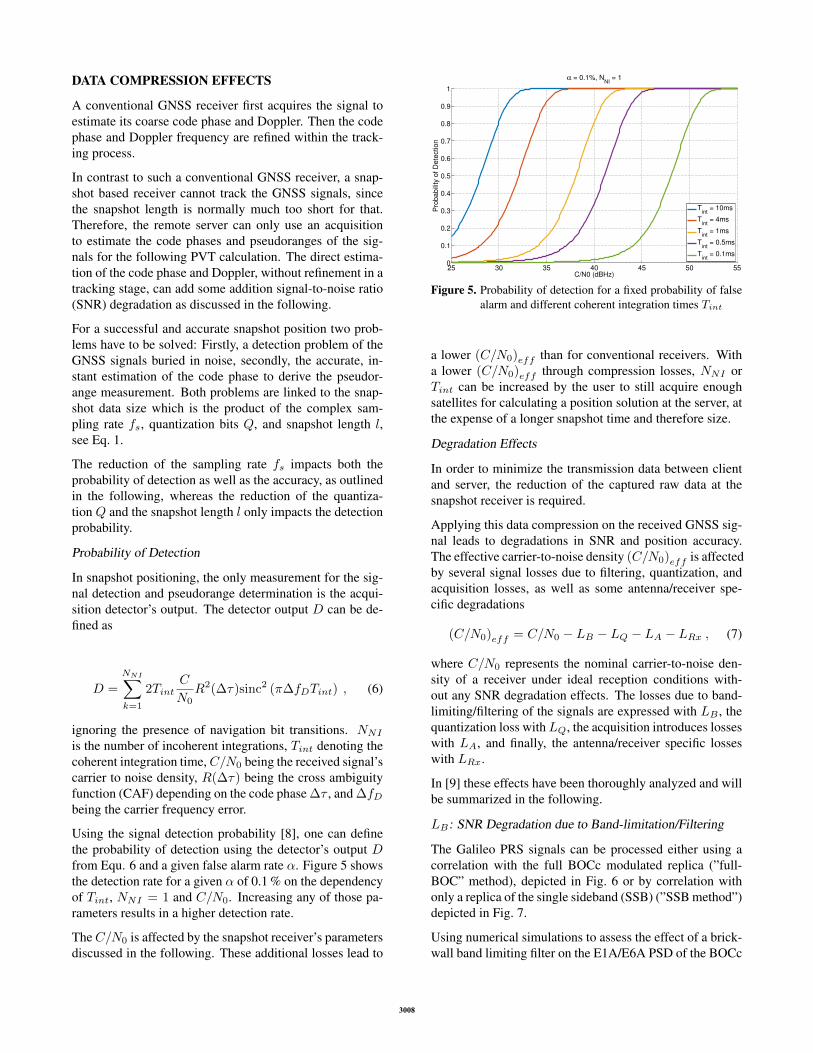
Using the signal detection probability [8], one can definethe probability of detection using the detector’s output Dfrom Equ. 6 and a given false alarm rate α. Figure 5 showsthe detection rate for a given α of 0.1 % on the dependencyof Tint, NNI = 1 and C/N0. Increasing any of those pa-rameters results in a higher detection rate.
TheC/N0 is affected by the snapshot receiver’s parametersdiscussed in the following. These additional losses lead to
25 30 35 40 45 50 550
0.1
0.2
0.3
0.4
0.5
0.6
0.7
0.8
0.9
1
C/N0 (dBHz)
Pro
babili
ty o
f D
ete
ction
α = 0.1%, NNI
= 1
Tint
= 10ms
Tint
= 4ms
Tint
= 1ms
Tint
= 0.5ms
Tint
= 0.1ms
Figure 5. Probability of detection for a fixed probability of falsealarm and different coherent integration times Tint
a lower (C/N0)eff than for conventional receivers. Witha lower (C/N0)eff through compression losses, NNI orTint can be increased by the user to still acquire enoughsatellites for calculating a position solution at the server, atthe expense of a longer snapshot time and therefore size.
Degradation Effects
In order to minimize the transmission data between clientand server, the reduction of the captured raw data at thesnapshot receiver is required.
Applying this data compression on the received GNSS sig-nal leads to degradations in SNR and position accuracy.The effective carrier-to-noise density (C/N0)eff is affectedby several signal losses due to filtering, quantization, andacquisition losses, as well as some antenna/receiver spe-cific degradations
(C/N0)eff = C/N0 − LB − LQ − LA − LRx , (7)
where C/N0 represents the nominal carrier-to-noise den-sity of a receiver under ideal reception conditions with-out any SNR degradation effects. The losses due to band-limiting/filtering of the signals are expressed with LB , thequantization loss withLQ, the acquisition introduces losseswith LA, and finally, the antenna/receiver specific losseswith LRx.
In [9] these effects have been thoroughly analyzed and willbe summarized in the following.
LB : SNR Degradation due to Band-limitation/Filtering
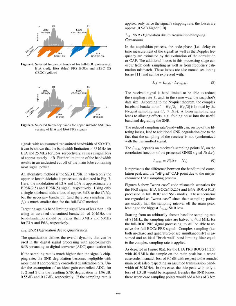
The Galileo PRS signals can be processed either using acorrelation with the full BOCc modulated replica (”full-BOC” method), depicted in Fig. 6 or by correlation withonly a replica of the single sideband (SSB) (”SSB method”)depicted in Fig. 7.
Using numerical simulations to assess the effect of a brick-wall band limiting filter on the E1A/E6A PSD of the BOCc
3008
Inphase
E6BC
BPSK(5)
E6A
BOCc(10,5)
E1A
BOCc(15,2.5)
E1BC
CBOC(6,1,1/11)
1278.75 MHz 1575.42 MHz
E6 E1
Figure 6. Selected frequency bands of for full-BOC processing:E1A (red), E6A (blue) PRS BOCc and E1BC OSCBOC (yellow)
Inphase
E6BC
BPSK(5)
E6A
BPSK(5)
E1A
BPSK(2.5)
E1BC
CBOC(6,1,1/11)
1278.75 MHz 1575.42 MHz
E6 E1
Figure 7. Selected frequency bands for upper sidelobe SSB pro-cessing of E1A and E6A PRS signals
signals with an assumed transmitted bandwidth of 50 MHz,it can be shown that the bandwidth limitation of 33 MHz forE1A and 25 MHz for E6A, respectively, causes a signal lossof approximately 1 dB. Further limitation of the bandwidthresults in an undesired cut off of the main lobe containingmost signal power.
An alternative method is the SSB BPSK, in which only theupper or lower sidelobe is processed as depicted in Fig. 7.Here, the modulation of E1A and E6A is approximately aBPSK(2.5) and BPSK(5) signal, respectively. Using onlya single sideband adds a loss of approx 3 dB to the C/N0,but the necessary bandwidth (and therefore sampling ratefs) is much smaller than for the full-BOC method.
Targeting again a band limiting signal loss of less than 1 dBusing an assumed transmitted bandwidth of 20 MHz, theband-limitation should be higher than 3 MHz and 6 MHzfor E1A and E6A, respectively.
LQ: SNR Degradation due to Quantization
The quantization defines the overall dynamic that can beused in the digital signal processing with approximately6 dB per analog-to-digital converter (ADC) quantization bit.
If the sampling rate is much higher than the signal’s chip-ping rate, the SNR degradation becomes negligible withmore than 3 appropriately controlled quantization bits. Un-der the assumption of an ideal gain-controlled ADC, for1, 2 and 3 bits the resulting SNR degradation is 1.96 dB,0.55 dB and 0.17 dB, respectively. If the sampling rate is
approx. only twice the signal’s chipping rate, the losses areapprox. 0.5 dB higher [10].
LA: SNR Degradation due to Acquisition/SamplingConstraints
In the acquisition process, the code phase (i.e. delay ortime measurement of the signal) as well as the Doppler fre-quency are estimated by the evaluation of the correlationor CAF. The additional losses in this processing stage canoccur from code sampling as well as from frequency esti-mation mismatch. These losses are also named scallopinglosses [11] and can be expressed with:
LA = Lcode · LDoppler (8)
The received signal is band-limited to be able to reducethe sampling rate fs and, in the same way, the snapshot’sdata size. According to the Nyquist theorem, the complexbaseband bandwidth of [−BF /2,+BF /2] is limited by theNyquist sampling rate (fs ≥ BF ). A lower sampling rateleads to aliasing effects, e.g. folding noise into the usefulband and degrading the SNR.
The reduced sampling rate/bandwidth can, on top of the fil-tering losses, lead to additional SNR degradation due to thefact that the sampling of the receiver is not synchronizedwith the transmitted signal.
The Lcode depends on receiver’s sampling pointsNs on thecorrelation function of the processed GNSS signal R(∆τ):
Lcode = R(∆τ −Ns) (9)
It represents the difference between the bandlimited corre-lation peak and the ”off-grid” CAF point due to the unsyn-chronized CAF sampling process.
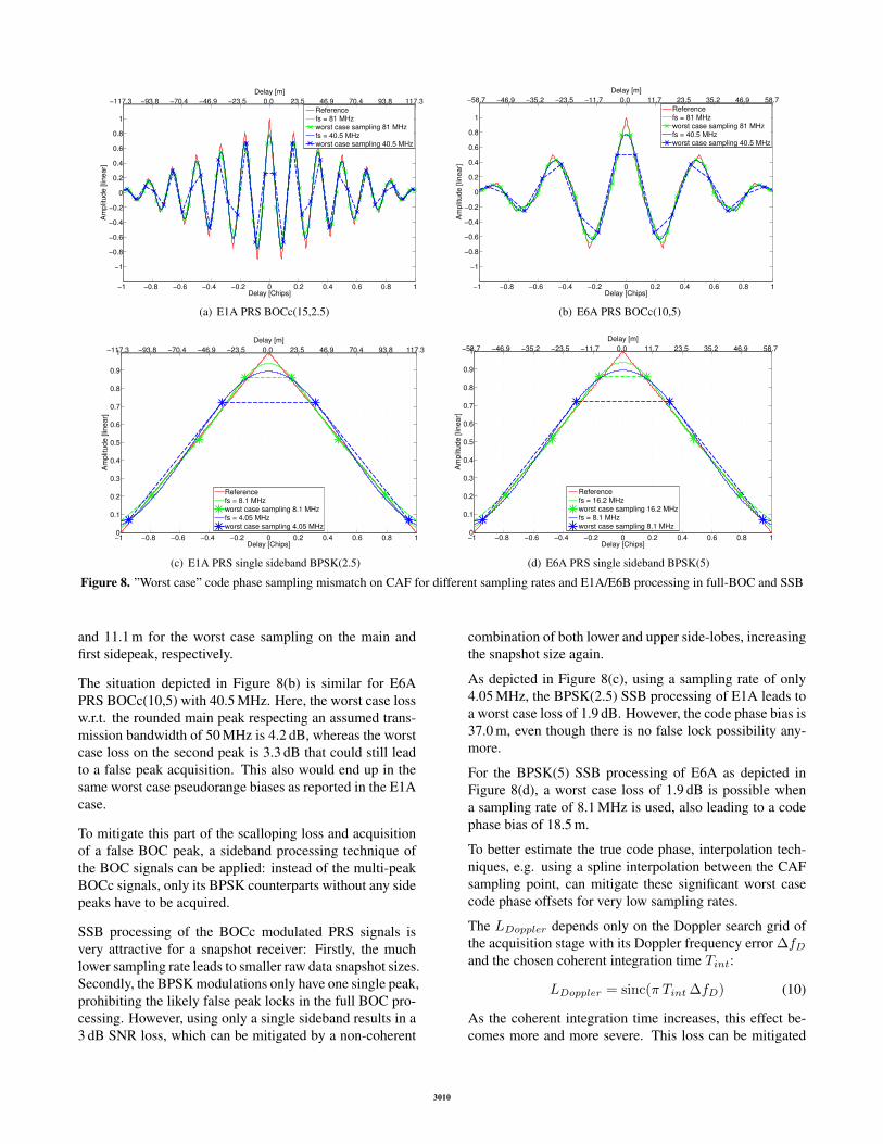
Figures 8 show ”worst case” code mismatch scenarios forthe PRS signal E1A BOCc(15,2.5) and E6A BOCc(10,5)processed in full BOC and SSB modes. These scenariosare regarded as ”worst case” since their sampling pointsare exactly half the sampling interval off the main peak,leading to the biggest Lcode SNR loss.
Starting from an arbitrarily chosen baseline sampling rateof 81 MHz, the sampling rates are halved to 40.5 MHz forthe full-BOC PRS signal processing, to still be able to re-ceive the full-BOCc PRS signal. Complex sampling (i.e.both in-phase and quadrature-phase simultaneously) is as-sumed and an ideal ”brick wall” band limiting filter equalto the complex sampling rate is applied.
As depicted in Figure 8(a), for the E1A PRS BOCc(15,2.5)with 40.5 MHz the sample on the main peak has a worstcase code mismatch loss of 9.5 dB with respect to the roundedmain peak (also respecting an assumed transmission band-width of 50 MHz). In this case, the side peak with only aloss of 1.3 dB would be acquired. Besides the SNR losses,these worst case sampling points would add a bias of 3.8 m
3009
−1 −0.8 −0.6 −0.4 −0.2 0 0.2 0.4 0.6 0.8 1
−1
−0.8
−0.6
−0.4
−0.2
0
0.2
0.4
0.6
0.8
1
Delay [Chips]
Am
plit
ud
e [
line
ar]
Referencefs = 81 MHzworst case sampling 81 MHzfs = 40.5 MHzworst case sampling 40.5 MHz
Figure 8. ”Worst case” code phase sampling mismatch on CAF for different sampling rates and E1A/E6B processing in full-BOC and SSB
and 11.1 m for the worst case sampling on the main andfirst sidepeak, respectively.
The situation depicted in Figure 8(b) is similar for E6APRS BOCc(10,5) with 40.5 MHz. Here, the worst case lossw.r.t. the rounded main peak respecting an assumed trans-mission bandwidth of 50 MHz is 4.2 dB, whereas the worstcase loss on the second peak is 3.3 dB that could still leadto a false peak acquisition. This also would end up in thesame worst case pseudorange biases as reported in the E1Acase.
To mitigate this part of the scalloping loss and acquisitionof a false BOC peak, a sideband processing technique ofthe BOC signals can be applied: instead of the multi-peakBOCc signals, only its BPSK counterparts without any sidepeaks have to be acquired.
SSB processing of the BOCc modulated PRS signals isvery attractive for a snapshot receiver: Firstly, the muchlower sampling rate leads to smaller raw data snapshot sizes.Secondly, the BPSK modulations only have one single peak,prohibiting the likely false peak locks in the full BOC pro-cessing. However, using only a single sideband results in a3 dB SNR loss, which can be mitigated by a non-coherent
combination of both lower and upper side-lobes, increasingthe snapshot size again.
As depicted in Figure 8(c), using a sampling rate of only4.05 MHz, the BPSK(2.5) SSB processing of E1A leads toa worst case loss of 1.9 dB. However, the code phase bias is37.0 m, even though there is no false lock possibility any-more.
For the BPSK(5) SSB processing of E6A as depicted inFigure 8(d), a worst case loss of 1.9 dB is possible whena sampling rate of 8.1 MHz is used, also leading to a codephase bias of 18.5 m.
To better estimate the true code phase, interpolation tech-niques, e.g. using a spline interpolation between the CAFsampling point, can mitigate these significant worst casecode phase offsets for very low sampling rates.
The LDoppler depends only on the Doppler search grid ofthe acquisition stage with its Doppler frequency error ∆fDand the chosen coherent integration time Tint:
LDoppler = sinc(π Tint ∆fD) (10)
As the coherent integration time increases, this effect be-comes more and more severe. This loss can be mitigated
3010
by selecting a fine enough Doppler grid spacing ∆fD lead-ing to an increased computational complexity on the serverprocessing side.
LRx: SNR Degradation due to Antenna/ReceiverConstraints
Finally, there are some antenna and receiver specific SNRdegradation losses which do not depend on the data com-pression.
A suitable antenna to receive the wideband PRS signals isrequired. Most GNSS signals, including the Galileo OSand PRS signals, are transmitted right hand circular polar-ized (RHCP). Consequently, a RHCP antenna should beused at the user terminal’s receiver. However, cheap andoften small antennas, e.g. the typical patch antennas, areonly linearly polarized, leading to an additional polariza-tion SNR degradation of 3 dB. Miniaturized antennas alsodo not have a high efficiency or gain, which can lead toa few dBs of additional SNR degradation. Lastly, the an-tenna reception bandwidth, including its RF filters, can addthe same SNR degradation to the signal as discussed in thebandwidth section of the data compression.
The noise figure (NF) of the data grabber (i.e. the antennawith receiver front-end) directly adds up to the SNR degra-dation. If an active antenna is used, the overall NF is dom-inated by the first low-noise amplifier (LNA) of the activeantenna according to Friis’ equation. A typical overall NFis approximately 1.5 to 2 dB. In case of a passive antenna,the overall NF can increase considerably, depending on theantenna efficiency with the cable and the LNA of the re-ceiver reaching 5 to 7 dB or even more.
EXPERIMENTAL SETUP AND RESULTS
Test Setup
An empirical analysis has been conducted for PRS snap-shot position solutions using Galileo E1A Pseudo-PRS sig-nals. Since the Galileo constellation is not yet complete andPseudo-PRS instead of real PRS signals shall be used tokeep the experimental setup unclassified, a Spirent GSS9000radio frequency constellation simulator (RFCS) is used tosimulate a full Galileo constellation scenario.
The Spirent GSS9000 can substitute the real PRS signals byPseudo-PRS or PRS-noise signals, where the E1A / E6APRS modulations of BOCc(15,2.5) and BOCc(10,5), re-spectively, are preserved, but the PRN chips are generatedusing the unclassified GPS P-Code. The performance interms of accuracy is equivalent to the real PRS signals,since the accuracy is only dependent on the modulation,scenario and data grabber emulation model, which is thesame for both PRS and Pseudo-PRS.
For our experiments, we simulated a static scenario (posi-tion 0 ◦/0 ◦) without atmospheric effects in Spirent’s Sim-GEN default Galileo constellation. The simulated satellites
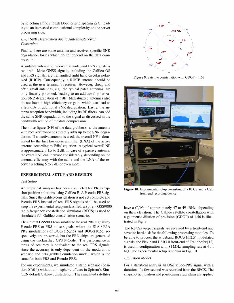
Figure 9. Satellite constellation with GDOP = 1.56
Figure 10. Experimental setup consisting of a RFCS and a USBfront-end recording device
have a C/N0 of approximately 47 to 49 dBHz, dependingon their elevation. The Galileo satellite constellation witha geometric dilution of precision (GDOP) of 1.56 is illus-trated in Fig. 9.
The RFCSs output signals are received by a front-end andsaved to hard disk for the following processing modules. Tobe able to process the wideband BOCc(15,2.5) modulatedsignals, the Flexiband USB3.0 front-end of Fraunhofer [12]is used in configuration with 81 MHz sampling rate at 4 bitI/Q. The experimental setup is shown in Fig. 10.
Emulation Model
For a statistical analysis an OS/Pseudo-PRS signal with aduration of a few second was recorded from the RFCS. Thesnapshot acquisition and positioning algorithms are applied
3011
Digital filtering Downsampling Re-Quantization
GNSS signal
generator
Acquisition
Snapshot
PVT
Replica generator
Horizontal error
estimation
RF Signal recorderA
f
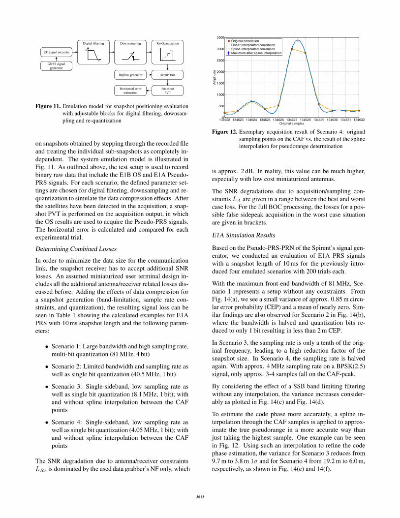
Figure 11. Emulation model for snapshot positioning evaluationwith adjustable blocks for digital filtering, downsam-pling and re-quantization
on snapshots obtained by stepping through the recorded fileand treating the individual sub-snapshots as completely in-dependent. The system emulation model is illustrated inFig. 11. As outlined above, the test setup is used to recordbinary raw data that include the E1B OS and E1A Pseudo-PRS signals. For each scenario, the defined parameter set-tings are chosen for digital filtering, downsampling and re-quantization to simulate the data compression effects. Afterthe satellites have been detected in the acquisition, a snap-shot PVT is performed on the acquisition output, in whichthe OS results are used to acquire the Pseudo-PRS signals.The horizontal error is calculated and compared for eachexperimental trial.
Determining Combined Losses
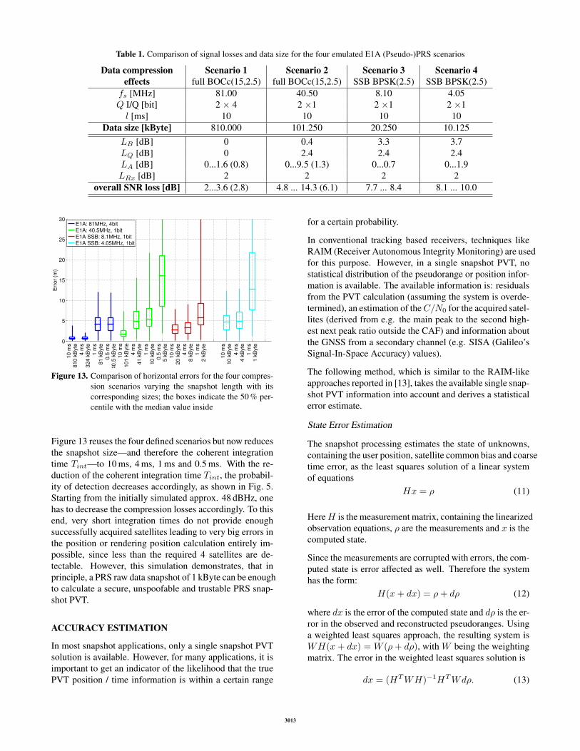
In order to minimize the data size for the communicationlink, the snapshot receiver has to accept additional SNRlosses. An assumed miniaturized user terminal design in-cludes all the additional antenna/receiver related losses dis-cussed before. Adding the effects of data compression fora snapshot generation (band-limitation, sample rate con-straints, and quantization), the resulting signal loss can beseen in Table 1 showing the calculated examples for E1APRS with 10 ms snapshot length and the following param-eters:
• Scenario 1: Large bandwidth and high sampling rate,multi-bit quantization (81 MHz, 4 bit)
• Scenario 2: Limited bandwidth and sampling rate aswell as single bit quantization (40.5 MHz, 1 bit)
• Scenario 3: Single-sideband, low sampling rate aswell as single bit quantization (8.1 MHz, 1 bit); withand without spline interpolation between the CAFpoints
• Scenario 4: Single-sideband, low sampling rate aswell as single bit quantization (4.05 MHz, 1 bit); withand without spline interpolation between the CAFpoints
The SNR degradation due to antenna/receiver constraintsLRx is dominated by the used data grabber’s NF only, which
Figure 12. Exemplary acquisition result of Scenario 4: originalsampling points on the CAF vs. the result of the splineinterpolation for pseudorange determination
is approx. 2 dB. In reality, this value can be much higher,especially with low cost miniaturized antennas.
The SNR degradations due to acquisition/sampling con-straints LA are given in a range between the best and worstcase loss. For the full BOC processing, the losses for a pos-sible false sidepeak acquisition in the worst case situationare given in brackets.
E1A Simulation Results
Based on the Pseudo-PRS-PRN of the Spirent’s signal gen-erator, we conducted an evaluation of E1A PRS signalswith a snapshot length of 10 ms for the previously intro-duced four emulated scenarios with 200 trials each.
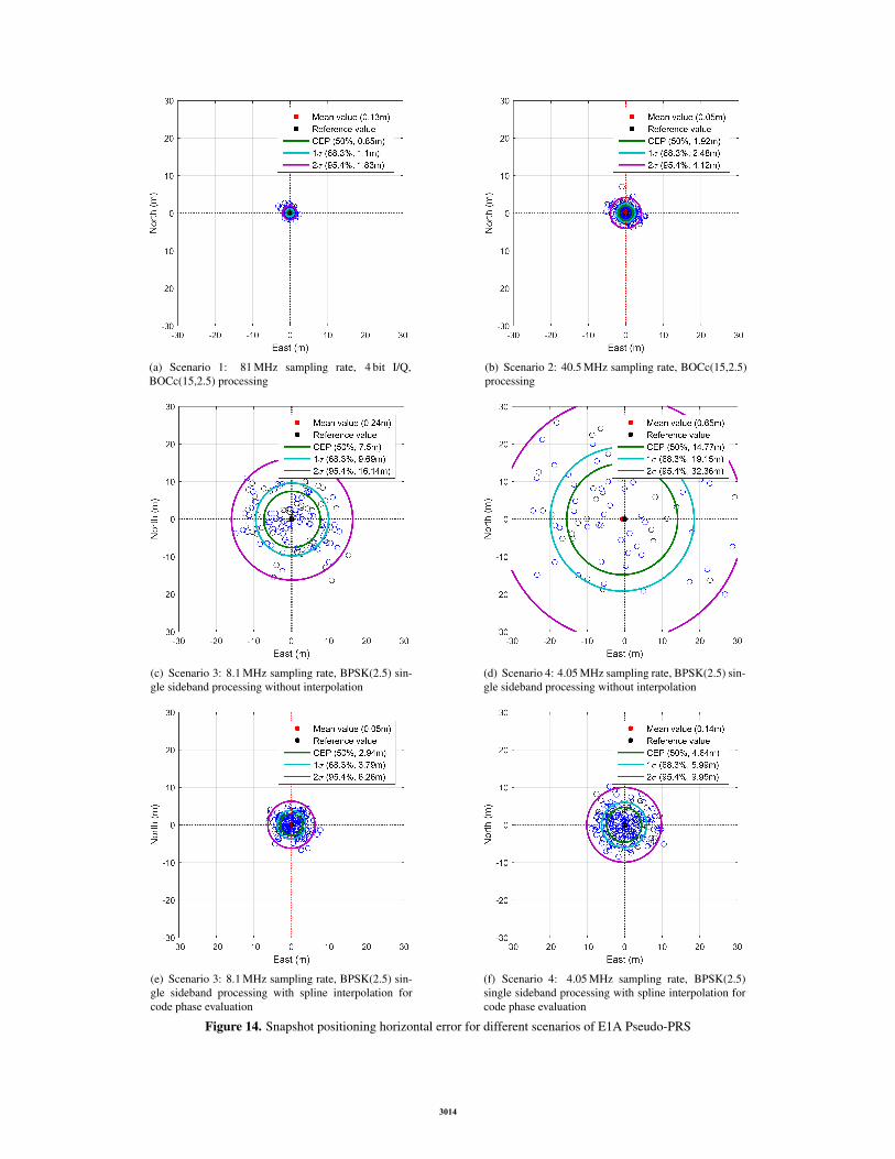
With the maximum front-end bandwidth of 81 MHz, Sce-nario 1 represents a setup without any constraints. FromFig. 14(a), we see a small variance of approx. 0.85 m circu-lar error probability (CEP) and a mean of nearly zero. Sim-ilar findings are also observed for Scenario 2 in Fig. 14(b),where the bandwidth is halved and quantization bits re-duced to only 1 bit resulting in less than 2 m CEP.
In Scenario 3, the sampling rate is only a tenth of the orig-inal frequency, leading to a high reduction factor of thesnapshot size. In Scenario 4, the sampling rate is halvedagain. With approx. 4 MHz sampling rate on a BPSK(2.5)signal, only approx. 3-4 samples fall on the CAF-peak.
By considering the effect of a SSB band limiting filteringwithout any interpolation, the variance increases consider-ably as plotted in Fig. 14(c) and Fig. 14(d).
To estimate the code phase more accurately, a spline in-terpolation through the CAF samples is applied to approx-imate the true pseudorange in a more accurate way thanjust taking the highest sample. One example can be seenin Fig. 12. Using such an interpolation to refine the codephase estimation, the variance for Scenario 3 reduces from9.7 m to 3.8 m 1σ and for Scenario 4 from 19.2 m to 6.0 m,respectively, as shown in Fig. 14(e) and 14(f).
3012
Table 1. Comparison of signal losses and data size for the four emulated E1A (Pseudo-)PRS scenarios
Figure 13. Comparison of horizontal errors for the four compres-sion scenarios varying the snapshot length with itscorresponding sizes; the boxes indicate the 50 % per-centile with the median value inside
Figure 13 reuses the four defined scenarios but now reducesthe snapshot size—and therefore the coherent integrationtime Tint—to 10 ms, 4 ms, 1 ms and 0.5 ms. With the re-duction of the coherent integration time Tint, the probabil-ity of detection decreases accordingly, as shown in Fig. 5.Starting from the initially simulated approx. 48 dBHz, onehas to decrease the compression losses accordingly. To thisend, very short integration times do not provide enoughsuccessfully acquired satellites leading to very big errors inthe position or rendering position calculation entirely im-possible, since less than the required 4 satellites are de-tectable. However, this simulation demonstrates, that inprinciple, a PRS raw data snapshot of 1 kByte can be enoughto calculate a secure, unspoofable and trustable PRS snap-shot PVT.
ACCURACY ESTIMATION
In most snapshot applications, only a single snapshot PVTsolution is available. However, for many applications, it isimportant to get an indicator of the likelihood that the truePVT position / time information is within a certain range
for a certain probability.
In conventional tracking based receivers, techniques likeRAIM (Receiver Autonomous Integrity Monitoring) are usedfor this purpose. However, in a single snapshot PVT, nostatistical distribution of the pseudorange or position infor-mation is available. The available information is: residualsfrom the PVT calculation (assuming the system is overde-termined), an estimation of theC/N0 for the acquired satel-lites (derived from e.g. the main peak to the second high-est next peak ratio outside the CAF) and information aboutthe GNSS from a secondary channel (e.g. SISA (Galileo’sSignal-In-Space Accuracy) values).
The following method, which is similar to the RAIM-likeapproaches reported in [13], takes the available single snap-shot PVT information into account and derives a statisticalerror estimate.
State Error Estimation
The snapshot processing estimates the state of unknowns,containing the user position, satellite common bias and coarsetime error, as the least squares solution of a linear systemof equations
Hx = ρ (11)
HereH is the measurement matrix, containing the linearizedobservation equations, ρ are the measurements and x is thecomputed state.
Since the measurements are corrupted with errors, the com-puted state is error affected as well. Therefore the systemhas the form:
H(x+ dx) = ρ+ dρ (12)
where dx is the error of the computed state and dρ is the er-ror in the observed and reconstructed pseudoranges. Usinga weighted least squares approach, the resulting system isWH(x+ dx) = W (ρ+ dρ), with W being the weightingmatrix. The error in the weighted least squares solution is
Figure 14. Snapshot positioning horizontal error for different scenarios of E1A Pseudo-PRS
3014
Its corresponding state error covariance matrix is:
cov(dx) = E[dxdxT ] (14)
= E[(HTWH)−1HTWdρdρTWH(HTWH)−1](15)
= (HTWH)−1HTWcov(dρ)WH(HTWH)−1
(16)
Based on the previous computation, the corresponding choiceof the weighting matrix would be
W = cov(dρ)−1 =
1σ21
0 · · ·
0. . . . . .
.... . . 1
σ2N
(17)
with σ2i being the range measurements’ variances consist-
ing of
σ2i = σ2
SISi+ σ2
RXi. (18)
σ2SISi
is the satellite error reported in the navigation mes-sage (e.g. for GPS the User Range Accuracy (URA) andfor Galileo the SISA (Signal-in-Space Accuracy)) togetherwith remaining errors from the atmosphere.
σ2RXi
is the result of firstly, the common receiver range er-ror due to noise, secondly, the influence of received sig-nal’s C/N0 and thirdly, the range error resulting from non-optimal estimation of the acquisition function’s code phase(e.g. coming from limited number of samples / interpola-tion) including potential multipath.
With this weighting approach, the state error covariancematrix is:
cov(dx) = (HTWH)−1 (19)
=
σ2xx σ2
xy σ2xz σ2
xb σ2xtc
σ2yx σ2
yy σ2yz σ2
yb σ2ytc
σ2zx σ2
zy σ2zz σ2
zb σ2ztc
σ2bx σ2
by σ2bz σ2
bb σ2btc
σ2tcx σ2
tcy σ2tcz σ2
tcbσ2tctc
(20)
This covariance matrix determines the estimated positionerror circle similar as in the case of DOP and URA/SISAvalues, as shown in [13]. The distance root mean squareerror (RMSE) is defined as
CEP68 = RMSE =√σ2xx + σ2
yy (21)
where CEP is Circular Error Probability. Similarly, all otherCEPx values can be formed using the method presentedin [14].
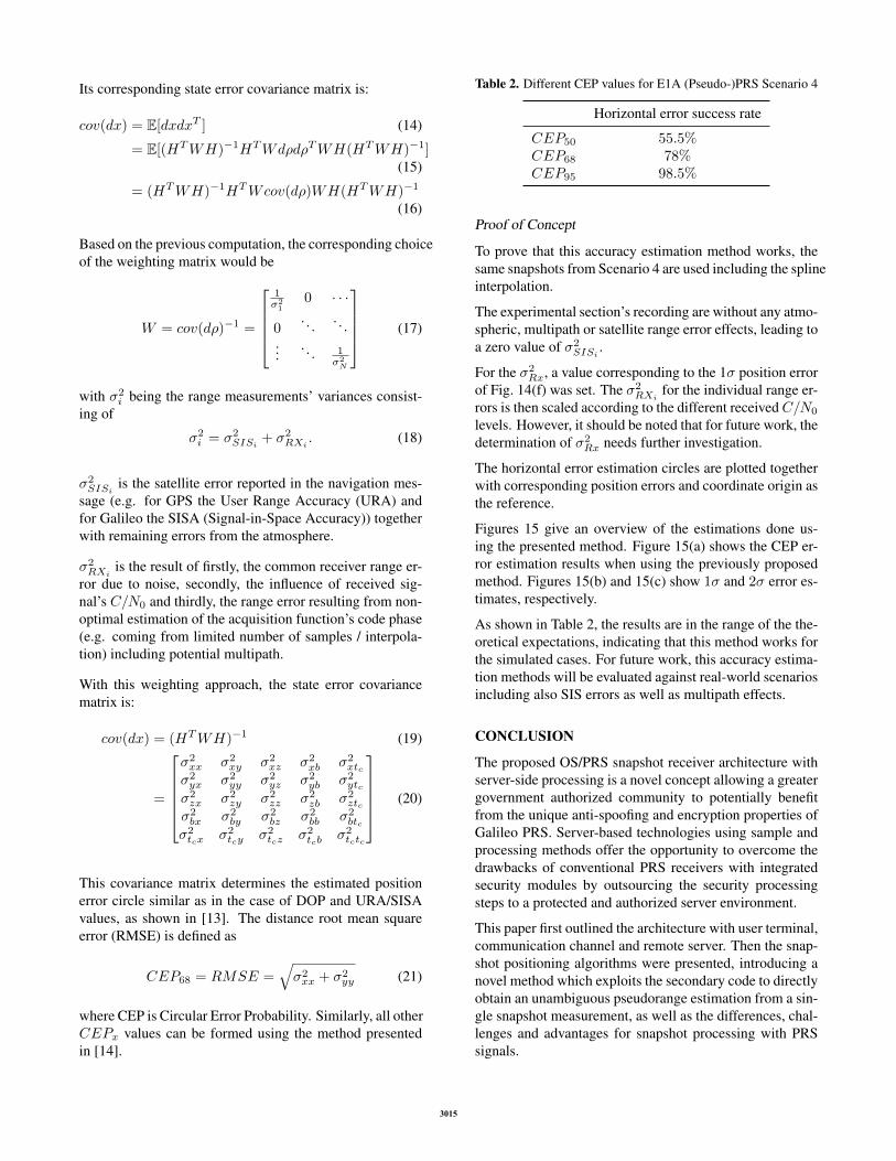
Table 2. Different CEP values for E1A (Pseudo-)PRS Scenario 4
Horizontal error success rate
CEP50 55.5%CEP68 78%CEP95 98.5%
Proof of Concept
To prove that this accuracy estimation method works, thesame snapshots from Scenario 4 are used including the splineinterpolation.
The experimental section’s recording are without any atmo-spheric, multipath or satellite range error effects, leading toa zero value of σ2
SISi.
For the σ2Rx, a value corresponding to the 1σ position error
of Fig. 14(f) was set. The σ2RXi
for the individual range er-rors is then scaled according to the different receivedC/N0
levels. However, it should be noted that for future work, thedetermination of σ2
Rx needs further investigation.
The horizontal error estimation circles are plotted togetherwith corresponding position errors and coordinate origin asthe reference.
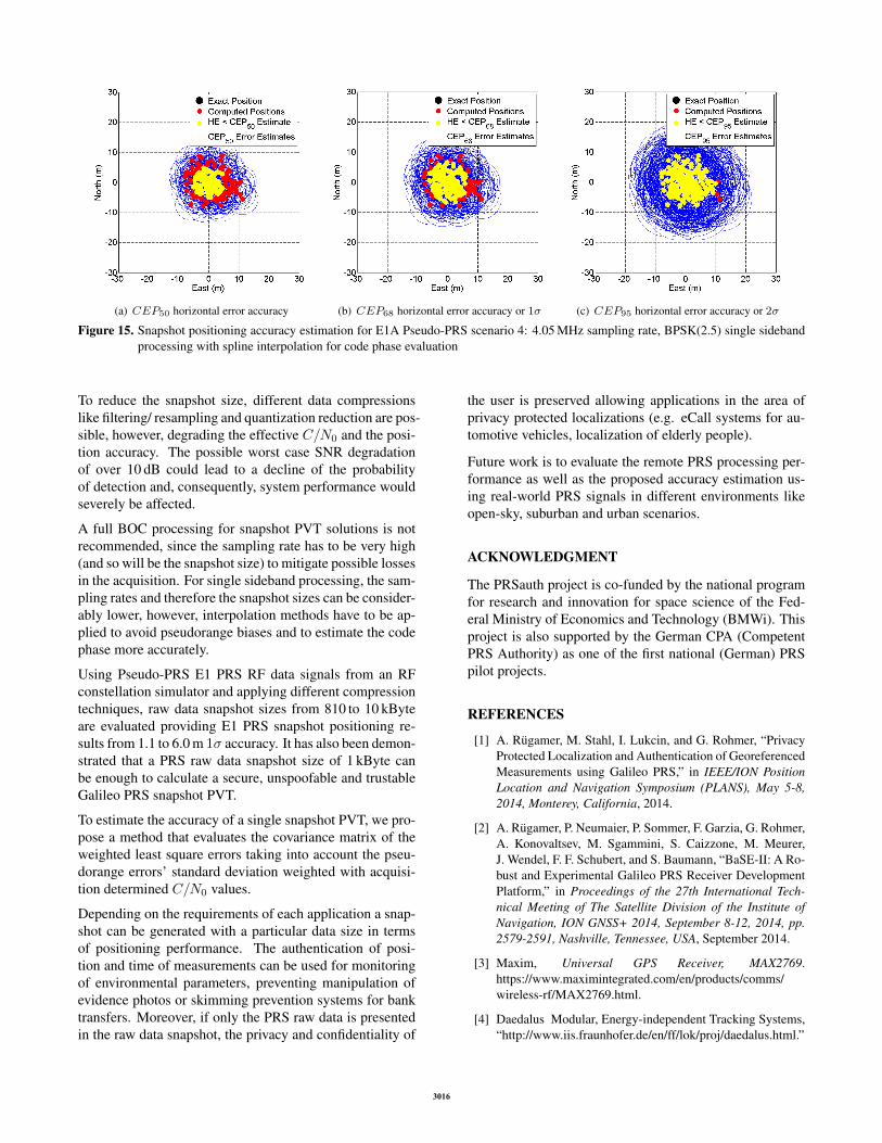
Figures 15 give an overview of the estimations done us-ing the presented method. Figure 15(a) shows the CEP er-ror estimation results when using the previously proposedmethod. Figures 15(b) and 15(c) show 1σ and 2σ error es-timates, respectively.
As shown in Table 2, the results are in the range of the the-oretical expectations, indicating that this method works forthe simulated cases. For future work, this accuracy estima-tion methods will be evaluated against real-world scenariosincluding also SIS errors as well as multipath effects.
CONCLUSION
The proposed OS/PRS snapshot receiver architecture withserver-side processing is a novel concept allowing a greatergovernment authorized community to potentially benefitfrom the unique anti-spoofing and encryption properties ofGalileo PRS. Server-based technologies using sample andprocessing methods offer the opportunity to overcome thedrawbacks of conventional PRS receivers with integratedsecurity modules by outsourcing the security processingsteps to a protected and authorized server environment.
This paper first outlined the architecture with user terminal,communication channel and remote server. Then the snap-shot positioning algorithms were presented, introducing anovel method which exploits the secondary code to directlyobtain an unambiguous pseudorange estimation from a sin-gle snapshot measurement, as well as the differences, chal-lenges and advantages for snapshot processing with PRSsignals.
3015
(a) CEP50 horizontal error accuracy (b) CEP68 horizontal error accuracy or 1σ (c) CEP95 horizontal error accuracy or 2σ
Figure 15. Snapshot positioning accuracy estimation for E1A Pseudo-PRS scenario 4: 4.05 MHz sampling rate, BPSK(2.5) single sidebandprocessing with spline interpolation for code phase evaluation
To reduce the snapshot size, different data compressionslike filtering/ resampling and quantization reduction are pos-sible, however, degrading the effective C/N0 and the posi-tion accuracy. The possible worst case SNR degradationof over 10 dB could lead to a decline of the probabilityof detection and, consequently, system performance wouldseverely be affected.
A full BOC processing for snapshot PVT solutions is notrecommended, since the sampling rate has to be very high(and so will be the snapshot size) to mitigate possible lossesin the acquisition. For single sideband processing, the sam-pling rates and therefore the snapshot sizes can be consider-ably lower, however, interpolation methods have to be ap-plied to avoid pseudorange biases and to estimate the codephase more accurately.
Using Pseudo-PRS E1 PRS RF data signals from an RFconstellation simulator and applying different compressiontechniques, raw data snapshot sizes from 810 to 10 kByteare evaluated providing E1 PRS snapshot positioning re-sults from 1.1 to 6.0 m 1σ accuracy. It has also been demon-strated that a PRS raw data snapshot size of 1 kByte canbe enough to calculate a secure, unspoofable and trustableGalileo PRS snapshot PVT.
To estimate the accuracy of a single snapshot PVT, we pro-pose a method that evaluates the covariance matrix of theweighted least square errors taking into account the pseu-dorange errors’ standard deviation weighted with acquisi-tion determined C/N0 values.
Depending on the requirements of each application a snap-shot can be generated with a particular data size in termsof positioning performance. The authentication of posi-tion and time of measurements can be used for monitoringof environmental parameters, preventing manipulation ofevidence photos or skimming prevention systems for banktransfers. Moreover, if only the PRS raw data is presentedin the raw data snapshot, the privacy and confidentiality of
the user is preserved allowing applications in the area ofprivacy protected localizations (e.g. eCall systems for au-tomotive vehicles, localization of elderly people).
Future work is to evaluate the remote PRS processing per-formance as well as the proposed accuracy estimation us-ing real-world PRS signals in different environments likeopen-sky, suburban and urban scenarios.
ACKNOWLEDGMENT
The PRSauth project is co-funded by the national programfor research and innovation for space science of the Fed-eral Ministry of Economics and Technology (BMWi). Thisproject is also supported by the German CPA (CompetentPRS Authority) as one of the first national (German) PRSpilot projects.
REFERENCES
[1] A. Rugamer, M. Stahl, I. Lukcin, and G. Rohmer, “PrivacyProtected Localization and Authentication of GeoreferencedMeasurements using Galileo PRS,” in IEEE/ION PositionLocation and Navigation Symposium (PLANS), May 5-8,2014, Monterey, California, 2014.
[2] A. Rugamer, P. Neumaier, P. Sommer, F. Garzia, G. Rohmer,A. Konovaltsev, M. Sgammini, S. Caizzone, M. Meurer,J. Wendel, F. F. Schubert, and S. Baumann, “BaSE-II: A Ro-bust and Experimental Galileo PRS Receiver DevelopmentPlatform,” in Proceedings of the 27th International Tech-nical Meeting of The Satellite Division of the Institute ofNavigation, ION GNSS+ 2014, September 8-12, 2014, pp.2579-2591, Nashville, Tennessee, USA, September 2014.
[5] F. S. T. Van Diggelen, A-GPS: Assisted GPS, GNSS, andSBAS, GNSS Technology and Applications Series. ArtechHouse, 2009.
[6] C. Palestini, Synchronization and detection techniques fornavigation and communication systems. PhD thesis, Uni-versity of Bologna, 2010.
[7] G. E. Corazza, C. Palestini, R. Pedone, and M. Vil-lanti, “Galileo primary code acquisition based on multi-hypothesis secondary code ambiguity elimination,” in Pro-ceedings of 20th International Technical Meeting of theSatellite Division, 2007.
[8] S. M. Kay, Fundamentals of Statistical Signal Processing:Detection Theory, vol. 2 of Prentice-Hall Signal processingseries. Prentice Hall, 1998.
[9] D. Rubino, A. Rugamer, I. Lukcin, S. Taschke, M. Stahl, andW. Felber, “Galileo PRS Snapshot Receiver with Server-side Positioning and Time Verification,” in Proceedings ofDGON POSNAV 2016, Berlin, Germany, July 2016.
[10] C. Hegarty, “Analytical Model for GNSS Receiver Imple-mentation Losses,” in Proceedings of the 22nd InternationalTechnical Meeting of The Satellite Division of the Instituteof Navigation (ION GNSS 2009), Savannah, GA, pp. 3165–3178, September 2009.
[11] J. Betz, Engineering Satellite-Based Navigation and Tim-ing: Global Navigation Satellite Systems, Signals, and Re-ceivers. Wiley, 2015.
[12] A. Rugamer, F. Forster, M. Stahl, and G. Rohmer, “Featuresand Applications of the Adaptable Flexiband USB3.0 Front-end,” in Proceedings of the ION GNSS+, (Tampa, Florida,USA), pp. 8 – 12, 2014.
[13] E. D. Kaplan and C. J. Hegarty, Understanding GPS: Prin-ciples and Applications. Artech House, 2006.
[14] W. E. Hoover, “Algorithms for Confidence Circles and El-lipses,” 1984.