SecureCore: A Multicore based Intrusion Detection Architecture for Real-time Embedded Systems Man-Ki Yoon 1 , Sibin Mohan 2 , Jaesik Choi 1 , Jung-Eun Kim 1 and Lui Sha 1 1 Dept. of Computer Science, University of Illinois at Urbana-Champaign, Urbana IL 61801. 2 Information Trust Institute. University of Illinois at Urbana-Champaign, Urbana IL 61801. [mkyoon, sibin, jaesik, jekim314, lrs]@illinois.edu Abstract—Security violations are becoming more common in real- time systems – an area that was considered to be invulnerable in the past – as evidenced by the recent W32.Stuxnet and Duqu worms. A failure to protect such systems from malicious entities could result in significant harm to both, humans as well as the environment. The increasing use of multicore architectures in such systems exacerbates the problem since shared resources on these processors increase the risk of of being compromised. In this paper, we present the SecureCore framework that, coupled with novel monitoring techniques, is able to improve the security of real- time embedded systems. We aim to detect malicious activities by analyzing and observing the inherent properties of the real-time system using statistical analyses of their execution profiles. With careful analysis based on these profiles, we are able to detect malicious code execution as soon as it happens and also ensure that the physical system remains safe. I. I NTRODUCTION Many safety-critical systems 1 such as advanced automo- tive/avionics systems, power plants and industrial automation systems have traditionally been considered to be invulnerable against software security breaches. This was particularly the case since, in general, such systems are physically isolated from the outside world and also used specialized protocols. However, many recent successful security attacks on embedded control systems such as the ‘W32.Stuxnet’ infection of Iran’s nuclear power plant [27] and malicious code injection into the telematics units of modern automobiles [13] and attacks on UAVs [23] call for a rethink of the security of safety-critical embedded systems. Another recent trend is that of multicore processing. Such processors are finding wide use in a variety of domains and em- bedded systems are no exception. The increase in performance, reduction in power consumption, and reduced sizes of systems using multicore processors (a single board instead of multiple boards) makes them very attractive for use in safety-critical em- bedded systems. A problem with the use of multicore processors in such systems is that of shared resources – components such as caches, buses, memory, etc. are shared across the multiple cores and could result in security vulnerabilities [19]. E.g., malicious entities could snoop on privileged information used/generated by critical code running on alternate cores, high-priority tasks could be prevented from executing by a denial of service attack on the shared resources (e.g., keeping the bus occupied by large DMA transfers could prevent the high priority task from obtaining the memory reads it requested), etc. Hence, there is a need for a comprehensive solution where multicore processors could be 1 A ‘safety-critical’ or ‘life-critical’ system is one where failure or malfunction may result in death or serious injury to humans, loss or severe damage to equipment and/or the environment. used in safety-critical systems in a safe and secure manner. In fact, the very nature of such processors (i.e., the parallel cores and the convenience they provide) could be used to improve the overall security of the system. In this paper, we present SecureCore, a secure and reliable multicore architecture solution to tackle security vulnerabilities in real-time embedded systems. We specifically pursue an approach to entrusting certain CPU cores in a multicore processor with the role of monitoring and intrusion detection 2 . The use of multicore processors has inherent advantages over off-chip security devices: (i) a CPU core is able to more closely monitor the execution behavior of software running on the other (potentially) unsecured core(s); (ii) the mechanisms cannot be tampered with easily or reverse-engineered and Section III provides further details about the SecureCore Architecture. We also introduce novel techniques to observe inherent prop- erties of the real-time code executing on the monitored core in Section IV – properties such as execution time for instance. These properties tend to be fairly deterministic in such real-time systems and hence can be used as a way of detecting anomalous behavior (indicative of malicious activity). These observations, in conjunction with the capabilities of the SecureCore architec- ture, significantly increase the security of the overall system by enhancing the abilities to detect intrusions. A key idea behind the proposed architecture and intrusion detection mechanism is that since real-time embedded control applications generally have regular timing behavior, an attack would inevitably alter its run-time timing signature from expected values [17]. Our architecture proposes a design so that a trusted entity, a ‘secure core’, can continuously monitor the run-time execution behavior of a real-time control application on an untrustworthy entity (henceforth referred to as the ‘monitored core’), in a non-intrusive manner. In case malicious behavior is detected, a reliable backup control application residing on the secure core takes control away from the infected core in order to guarantee stability and loss-less control for a physical system [22]. Since there will be some inherent variability in these properties – for instance due to changes in inputs, code complexity, etc. we used statistical learning-based mechanism for profiling the correct execution behavior of a sanitized system and then summarized it in an easy manner so that lookups and comparisons can be performed easily at runtime. In summary, this paper implements the following: (a) a novel 2 For this paper we will focus on the use of a dual-core processor setup where one core observes the other one. In future versions, we intend to study the tradeoffs regarding how many monitoring cores are required per set of observed cores.
Transcript
SecureCore: A Multicore based Intrusion DetectionArchitecture for Real-time Embedded Systems
Man-Ki Yoon1, Sibin Mohan2, Jaesik Choi1, Jung-Eun Kim1 and Lui Sha11 Dept. of Computer Science, University of Illinois at Urbana-Champaign, Urbana IL 61801.2 Information Trust Institute. University of Illinois at Urbana-Champaign, Urbana IL 61801.
Abstract—Security violations are becoming more common in real-time systems – an area that was considered to be invulnerablein the past – as evidenced by the recent W32.Stuxnet and Duquworms. A failure to protect such systems from malicious entitiescould result in significant harm to both, humans as well as theenvironment. The increasing use of multicore architectures in suchsystems exacerbates the problem since shared resources on theseprocessors increase the risk of of being compromised. In this paper,we present the SecureCore framework that, coupled with novelmonitoring techniques, is able to improve the security of real-time embedded systems. We aim to detect malicious activities byanalyzing and observing the inherent properties of the real-timesystem using statistical analyses of their execution profiles. Withcareful analysis based on these profiles, we are able to detectmalicious code execution as soon as it happens and also ensurethat the physical system remains safe.
I. INTRODUCTION
Many safety-critical systems 1 such as advanced automo-tive/avionics systems, power plants and industrial automationsystems have traditionally been considered to be invulnerableagainst software security breaches. This was particularly thecase since, in general, such systems are physically isolated fromthe outside world and also used specialized protocols. However,many recent successful security attacks on embedded controlsystems such as the ‘W32.Stuxnet’ infection of Iran’s nuclearpower plant [27] and malicious code injection into the telematicsunits of modern automobiles [13] and attacks on UAVs [23] callfor a rethink of the security of safety-critical embedded systems.
Another recent trend is that of multicore processing. Suchprocessors are finding wide use in a variety of domains and em-bedded systems are no exception. The increase in performance,reduction in power consumption, and reduced sizes of systemsusing multicore processors (a single board instead of multipleboards) makes them very attractive for use in safety-critical em-bedded systems. A problem with the use of multicore processorsin such systems is that of shared resources – components such ascaches, buses, memory, etc. are shared across the multiple coresand could result in security vulnerabilities [19]. E.g., maliciousentities could snoop on privileged information used/generated bycritical code running on alternate cores, high-priority tasks couldbe prevented from executing by a denial of service attack on theshared resources (e.g., keeping the bus occupied by large DMAtransfers could prevent the high priority task from obtainingthe memory reads it requested), etc. Hence, there is a need fora comprehensive solution where multicore processors could be
1A ‘safety-critical’ or ‘life-critical’ system is one where failure or malfunctionmay result in death or serious injury to humans, loss or severe damage toequipment and/or the environment.
used in safety-critical systems in a safe and secure manner. Infact, the very nature of such processors (i.e., the parallel coresand the convenience they provide) could be used to improve theoverall security of the system.
In this paper, we present SecureCore, a secure and reliablemulticore architecture solution to tackle security vulnerabilities inreal-time embedded systems. We specifically pursue an approachto entrusting certain CPU cores in a multicore processor with therole of monitoring and intrusion detection 2. The use of multicoreprocessors has inherent advantages over off-chip security devices:(i) a CPU core is able to more closely monitor the executionbehavior of software running on the other (potentially) unsecuredcore(s); (ii) the mechanisms cannot be tampered with easily orreverse-engineered and Section III provides further details aboutthe SecureCore Architecture.
We also introduce novel techniques to observe inherent prop-erties of the real-time code executing on the monitored corein Section IV – properties such as execution time for instance.These properties tend to be fairly deterministic in such real-timesystems and hence can be used as a way of detecting anomalousbehavior (indicative of malicious activity). These observations,in conjunction with the capabilities of the SecureCore architec-ture, significantly increase the security of the overall system byenhancing the abilities to detect intrusions. A key idea behindthe proposed architecture and intrusion detection mechanismis that since real-time embedded control applications generallyhave regular timing behavior, an attack would inevitably alterits run-time timing signature from expected values [17]. Ourarchitecture proposes a design so that a trusted entity, a ‘securecore’, can continuously monitor the run-time execution behaviorof a real-time control application on an untrustworthy entity(henceforth referred to as the ‘monitored core’), in a non-intrusivemanner. In case malicious behavior is detected, a reliable backupcontrol application residing on the secure core takes controlaway from the infected core in order to guarantee stability andloss-less control for a physical system [22]. Since there will besome inherent variability in these properties – for instance dueto changes in inputs, code complexity, etc. we used statisticallearning-based mechanism for profiling the correct executionbehavior of a sanitized system and then summarized it in aneasy manner so that lookups and comparisons can be performedeasily at runtime.
In summary, this paper implements the following: (a) a novel
2For this paper we will focus on the use of a dual-core processor setup whereone core observes the other one. In future versions, we intend to study thetradeoffs regarding how many monitoring cores are required per set of observedcores.
architecture based on a multicore platform that provides securitymechanisms for use in embedded real-time systems; (b) statisticallearning-based execution time-based intrusion detection mecha-nisms; and (c) Simplex [22] architecture-based reliablility. Allof these combined provides non-intrusive, invisible monitoringcapabilities and reliable, seamless control for real-time systems.
A. Assumptions
In this paper, the following assumptions are made without lossof generality: (i) We consider a CPU-based real-time controlapplication – i.e., a system consisting of periodic, independenttasks; the code does not include function pointers. (ii) We assumethe application runs on a single monitored core. The proposedintrusion detection method does not work with multiple moni-tored entities in the current form. (iii) We assume that the sizeof the input set (to the control application under consideration)is small. This can be justified by the fact that most real-timecontrol applications have a small footprint for input data (velocity,angle, etc.) within fairly narrow ranges. (iv) We assume thatthe execution time of the application is not unbounded. E.g.,the upper bounds for loops is known a-priori. However, thisassumption is not strictly required in this paper. It is sufficientto assume that (almost) all possible loop bounds are profiled. (v)Similarly, we assume there is no hidden execution flow path inthe application – all paths are present when being profiled.
II. MOTIVATION
A. Threat Model
The W32.Stuxnet worm [27] was able to successfully subvertoperator workstations and gain control of Iran’s nuclear powerplants through sophisticated attacks including the first knownPLC rootkits and use of multiple zero-day vulnerabilities. Theworm was able to intrude into the control system by first gainingaccess and then downloading attack code from a remote site. Themalware then gradually inflicted damage to the physical plant bysubstituting infected actuation commands for legitimate ones overa period of time. Despite the employment of several protectionand monitoring mechanisms, the control system could not detectthe intrusion and the attack until the physical damage to theplant was significant. In fact, such sophisticated systems havemany entry points that are vulnerable to potential attacks andthey often cannot be secured completely. Hence, there is needfor failure-prone monitoring methods.
In this paper, instead of trying to prevent and/or detect in-trusions at every vulnerable component, we intend to monitorand detect intrusions at the most critical component: in real-timecontrol systems, the primary concern is the safety of the physicalplant under control. Thus, we focus on detecting an intrusionthat directly targets the real-time control application. We assumethat regular security process was in place to ensure the securityduring the application design and development phases, i.e., theapplication is trustworthy initially. We consider malicious codethat was secretly embedded in the application, either by remoteattacks or during upgrades. The malicious code activates itselfat some point after the system initialization and then graduallytries to change, damage or even snoop on the physical state ofthe plant under control. We are not directly concerned with how
Monitored Core Reliable Secure Core
Hype
rviso
r OS / Bare-Metal Operating System
Plant
ComplexController
TimingTrace
Module
Scratch Pad
Memory
SecureMonitor
Decision Module
SafetyController
I/OProxy
Inter-CoreCommunication
Trace Sensor Data Actuation Command
ActuationCommand
Sensor Data
Fig. 1. SecureCore Architecture.
the malicious code gained entry, but more concerned with whathappens after that.
B. Use of Multicore Processor in Real-time Control Systems
Multicore processors are receiving wide attention from indus-tries due to their ability to support generic and high-end real-timeapplications that traditional control hardware, e.g., programmablelogic controllers (PLC), are unable to provide. This trend isespecially strong for instance in automotive industries [1], whereCPU-based real-time control applications have a significant pres-ence, e.g., engine control, anti-lock braking systems (ABS), etc.As previously introduced, it was shown that automotive controlapplications are increasingly vulnerable to security attacks asthey are more equipped with high-end and complex technolo-gies [13]. Although we do not specifically consider automotivecontrol applications, the use of the mechanisms presented in thispaper will naturally fit into the future development processesof safety-critical automotive components as the industries aremore moving toward employing more multicore-based real-timecontrol systems.
Also, the use of one or more cores for improving the security(and overall safety) of such systems is a big plus. Even thoughsome of the resources (cores in this case) are being used up, theincrease in security that is provided as a result definitely offsetsany losses in performance. Hence, the use of multicore processorsin secure real-time embedded systems will be beneficial to thecommunity.
III. SECURECORE ARCHITECTURE
In this section, we present the SecureCore Architecture, a se-cure and reliable multicore architecture that aids in the detectionof intrusions in embedded real-time systems and guarantees aseamless control to the physical system. We first introduce theoverall structure of the architecture and then discuss the designconsideration of each component in detail.
There exist several challenges in both, hardware as well assoftware, before these techniques could be implemented in a sat-isfactory manner. First, a protection mechanism must be providedto the secure core so that it is tamper-resistant (especially frommalicious activity on the unsecured/monitored cores). Second, thesecure core should be able to closely monitor the state of the othercore. However, the monitoring activity should be invisible as far
as the observe is concerned – this is mainly so that an attackershould not be able to deceive the intrusion detection mechanismsby means of replay attacks (i.e., replicating previously recordedexecution behavior of an application in its correct state). Third,in a multicore environment, an application will inevitably ex-perience a considerable variation in its execution time due tothe interference caused from inter-core resource contentions [21],[29]. Thus, the security invariant, i.e., the execution time profilein this paper 3, should be robust enough so that the intrusiondetection method(s) can effectively validate the cause of anysuch variations. Similarly, the method should be able to take intoaccount execution time variation caused by legitimate applicationcontexts such as differences in input sets and execution flow.Finally, the secure core should be able to guarantee loss-lesscontrol to the physical system that it manages even if the main,monitored, or control application is compromised. Each of theseissues is tackled in the following sections in this paper. How wesolved these problems is elaborated in the following sections.
A. High-Level Architecture
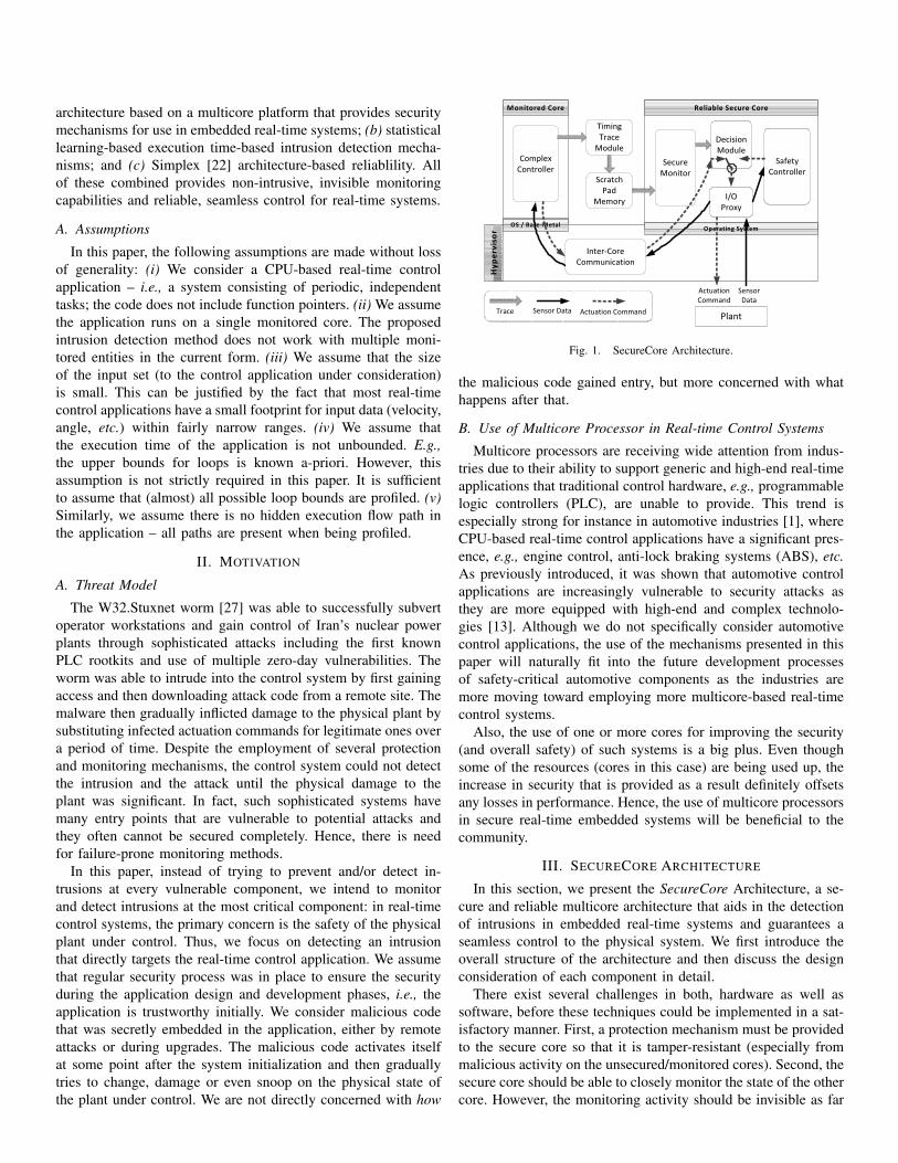
Figure 1 shows the high-level structure of the SecureCoreArchitecture. The system is composed of four major components– (a) the secure core (SC), (b) the monitored core (MC), (c)the on-chip Timing Trace Module (TTM) and (d) the hyper-visor. The system is built upon the concept of the Simplexarchitecture [22]: a safety controller and a decision module reston the secure core while a ‘complex’ controller (essentiallythe controller that manages the physical system) runs on themonitored core. Sensor data from the physical plant is fed to theboth controllers, each of which computes actuation commandsusing their own internal control logic. The decision module onthe secure core then forwards the appropriate command to theplant depending on a pre-computed ‘safety envelope’ for thephysical system. In normal circumstances, the plant is actuatedby commands from the complex controller. However, when anabnormal operation of the complex controller is detected (say, dueto unreliable/erroneous logic and faults), control is transferred tothe safety controller in order to maintain loss-less actuation ofthe physical plant. With this mechanism, the reliability of thecontrol actions can be guaranteed by the decision module andthe safety controller (that can be formally verified), providedhowever that all the entities are trustworthy. It is possible forthe decision module or safety controller to be compromised by asecurity attack. Furthermore, the complex controller may deceivethe decision module by providing a legitimate actuation valuewhile, for example, collecting critical system information thatcould be exploited during a future attack. Thus, it is importantto ensure a high security level for the system. In the followingsections, we describe how the security as well as the reliabilityof this basic Simplex mechanism can be enhanced by use of theSecureCore architecture.
B. Design Considerations
Our solution includes a hypervisor that provides a virtualiza-tion of hardware resources on our proposed SecureCore architec-ture through partitioning and consolidation [4]. In order to protect
3It could be memory references or I/O profile for other systems.
I/O Proxy(In)
Safety Controller
Complex Controller
Sensor Data
Secure Monitor + Decision Module
I/O Proxy(Out)
Actuation Command
TTM
SPM
Trace
Write
Read I/O Proxy(In)
Period
I nt er - C
ore
Commun
icat io
n I nte r - Cor e
Communication
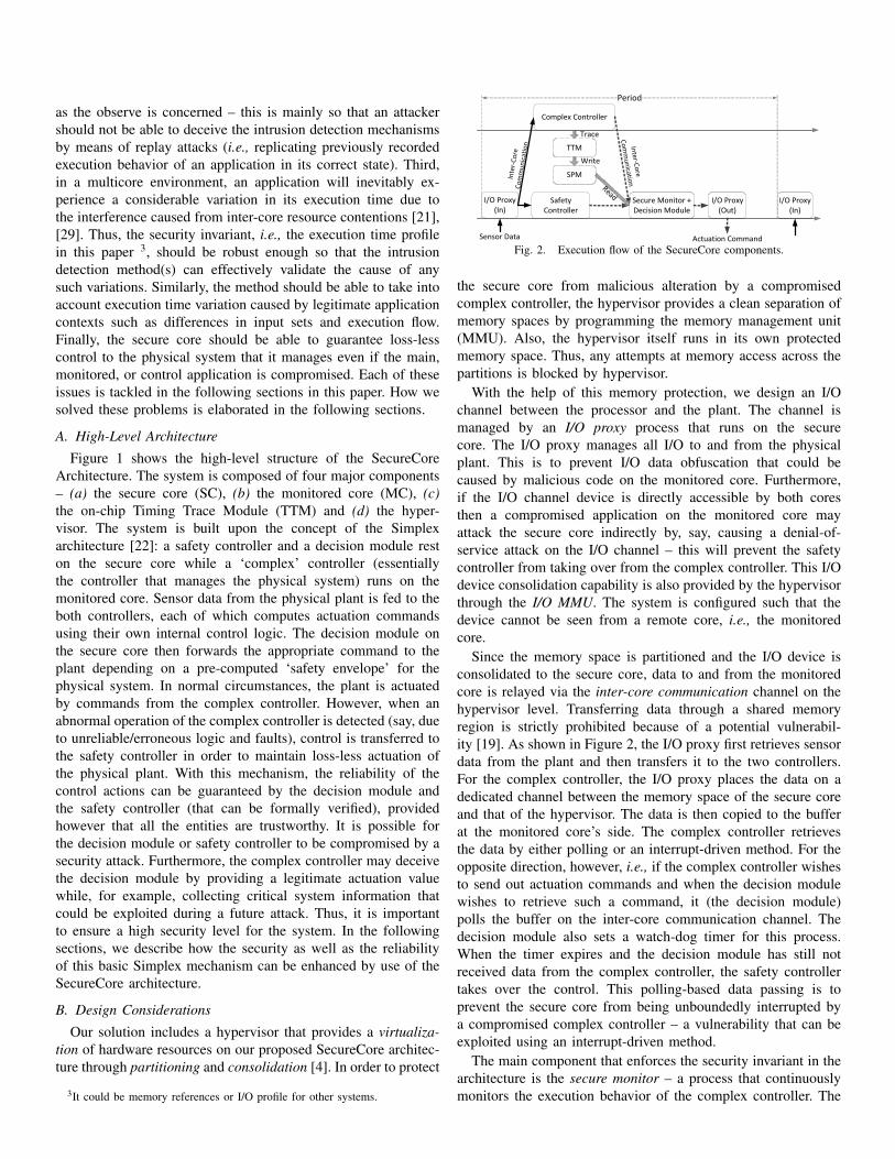
Fig. 2. Execution flow of the SecureCore components.
the secure core from malicious alteration by a compromisedcomplex controller, the hypervisor provides a clean separation ofmemory spaces by programming the memory management unit(MMU). Also, the hypervisor itself runs in its own protectedmemory space. Thus, any attempts at memory access across thepartitions is blocked by hypervisor.
With the help of this memory protection, we design an I/Ochannel between the processor and the plant. The channel ismanaged by an I/O proxy process that runs on the securecore. The I/O proxy manages all I/O to and from the physicalplant. This is to prevent I/O data obfuscation that could becaused by malicious code on the monitored core. Furthermore,if the I/O channel device is directly accessible by both coresthen a compromised application on the monitored core mayattack the secure core indirectly by, say, causing a denial-of-service attack on the I/O channel – this will prevent the safetycontroller from taking over from the complex controller. This I/Odevice consolidation capability is also provided by the hypervisorthrough the I/O MMU. The system is configured such that thedevice cannot be seen from a remote core, i.e., the monitoredcore.
Since the memory space is partitioned and the I/O device isconsolidated to the secure core, data to and from the monitoredcore is relayed via the inter-core communication channel on thehypervisor level. Transferring data through a shared memoryregion is strictly prohibited because of a potential vulnerabil-ity [19]. As shown in Figure 2, the I/O proxy first retrieves sensordata from the plant and then transfers it to the two controllers.For the complex controller, the I/O proxy places the data on adedicated channel between the memory space of the secure coreand that of the hypervisor. The data is then copied to the bufferat the monitored core’s side. The complex controller retrievesthe data by either polling or an interrupt-driven method. For theopposite direction, however, i.e., if the complex controller wishesto send out actuation commands and when the decision modulewishes to retrieve such a command, it (the decision module)polls the buffer on the inter-core communication channel. Thedecision module also sets a watch-dog timer for this process.When the timer expires and the decision module has still notreceived data from the complex controller, the safety controllertakes over the control. This polling-based data passing is toprevent the secure core from being unboundedly interrupted bya compromised complex controller – a vulnerability that can beexploited using an interrupt-driven method.
The main component that enforces the security invariant in thearchitecture is the secure monitor – a process that continuouslymonitors the execution behavior of the complex controller. The
ComplexController
TimingTrace
Module(TTM)
Scratch PadMemory
(SPM)
Monitored CoreTimestamp
Counter
ProgramCounter
Process IDSecure
Monitor
Secure Core
Fig. 3. Timing Trace Module.
secure monitor works in conjunction with an on-chip hardwareunit called the timing trace module (TTM). The details of securemonitor and TTM are discussed in Section III-C. The key role ofthe monitor is to detect if the run-time execution time signaturehas deviated from what is expected/has been profiled. If anyunexpected deviations are observed then the secure monitorinforms decision module and control is immediately switchedover to safety controller in the secure core. At the same time,the hypervisor is told to reset the monitored core and thenreload a clean copy of the complex controller binary from asecure memory region. Once the reset and reload is complete,the monitored core could, potentially, resume operation and takecontrol back. Of course, this could depend on the policy forrecovery that is implemented on the actual system. It could alsohappen that the monitored core is completely shut down and notrestarted until an engineer analyzes the issue and says it is safefor the monitored core to resume operations. This will preventsmart attackers from triggering constant back and forth switchesbetween the complex and simple controllers – events, that couldthemselves, cause harm to then physical system if timed correctly.In case a rapid recovery is required, the complex controller mayeven be implemented to run on a bare-metal executive [4] which,however, would require a modification of the legacy code.
As described above, the architecture relies heavily on thehypervisor. Thus, the entire secure mechanism can collapse if thehypervisor itself is compromised in the first place. Hence, it isassumed in this paper that the hypervisor forms part of the trustedbase; no malicious code is embedded in it. We note that while ahardware-enforced memory protection mechanism would furtherenhance the security of the hypervisor [28] we do not address inthis paper.
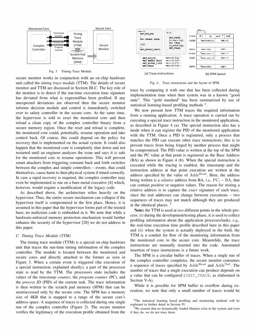
C. Timing Trace Module (TTM)
The timing trace module (TTM) is a special on-chip hardwareunit that traces the run-time timing information of the complexcontroller. The module is located between the monitored andsecure cores and directly attached to the former as seen inFigure 3. When a certain event is triggered (the execution ofa special instruction; explained shortly), a part of the processorstate is read by the TTM. The processors state includes thevalues of the timestamp counter, the program counter (PC), andthe process ID (PID) of the current task. The trace informationis then written to the scratch pad memory (SPM) that can beseen/accessed only by the secure core. The SPM has a memorysize of 4KB that is mapped to a range of the secure core’saddress space. A sequence of traces is collected during one singlerun of the complex controller (Figure 2). The secure monitorverifies the legitimacy of the execution profile obtained from the
Timestamp i+2PID BA AddrHeadTimestamp i Addr iTimestamp i+1 Addr i+1Addr i+2...
trace by comparing it with one that has been collected duringimplementation time when then system was in a known “goodstate”. This “gold standard” has been summarized by use ofstatistical learning-based profiling methods 4.
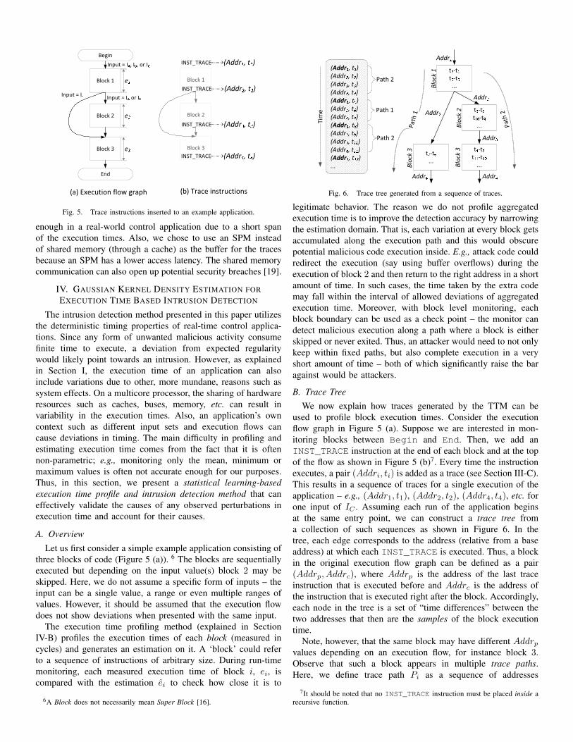
We now present how TTM traces the required informationfrom a running application. A trace operation is carried out byexecuting a special trace instruction in the monitored application,as described in Figure 4 (a). The special instruction also has amode when it can register the PID of the monitored applicationwith the TTM. Once a PID is registered, only a process thatmatches the PID can execute other trace instructions; this is toprevent traces from being forged by another process that mightbe compromised. The PID value is written at the top of the SPMand the PC value at that point is registered as the Base Address(BA) as shown in Figure 4 (b). When the special instruction isexecuted while the tracing is enabled, the timestamp and theinstruction address at that point execution are written at theaddress specified by the value of AddrHead. Here, the addressbeing written is a relative address from BA, i.e., PCi − BA, thatcan contain positive or negative values. The reason for storing arelative address is to capture the exact signature of each trace,since the real addresses can change between executions – twosequences of traces may not match although they are producedat the identical places. 5
Note: the TTM is used at two different points in the whole pro-cess: (i) during the development/testing phase, it is used to collectprofiling information about the application processes/tasks, e.g.,the real-time execution time profile described later in this paperand (ii) when the system is actually deployed in the field, theTTM is a conduit for flow of the monitoring information fromthe monitored core to the secure core. Meanwhile, the traceinstructions are manually inserted into the code. Automatedinsertion of trace instructions is a future work.
The SPM is a circular buffer of traces. When a single run ofthe complex controller completes, the secure monitor consumesa sequence of traces specified by AddrHead and AddrTail. Thenumber of traces that a single execution can produce depends ona value that can be configured (INST_TRACE, as elaborated inSection V-A).
While it is possible for SPM buffer to overflow during ex-ecution, we note that only a small number of traces would be
4The statistical learning based profiling and monitoring methods will beexplained in further detail in Section IV.
5We assume that no dynamically loaded libraries exist in the system and evenif they do, we do not trace them.
Begin
Block 1
Block 2
Block 3
End
Input = IC Input = IA or IBInput = IA, IB, or IC
e1e2e3
(a) Execution flow graph
Block 1
Block 2
Block 3
(b) Trace instructions
INST_TRACE
INST_TRACE
(Addr1, t1)(Addr2, t2)
INST_TRACE (Addr4, t4)INST_TRACE (Addr3, t3)
Fig. 5. Trace instructions inserted to an example application.
enough in a real-world control application due to a short spanof the execution times. Also, we chose to use an SPM insteadof shared memory (through a cache) as the buffer for the tracesbecause an SPM has a lower access latency. The shared memorycommunication can also open up potential security breaches [19].
IV. GAUSSIAN KERNEL DENSITY ESTIMATION FOREXECUTION TIME BASED INTRUSION DETECTION
The intrusion detection method presented in this paper utilizesthe deterministic timing properties of real-time control applica-tions. Since any form of unwanted malicious activity consumefinite time to execute, a deviation from expected regularitywould likely point towards an intrusion. However, as explainedin Section I, the execution time of an application can alsoinclude variations due to other, more mundane, reasons such assystem effects. On a multicore processor, the sharing of hardwareresources such as caches, buses, memory, etc. can result invariability in the execution times. Also, an application’s owncontext such as different input sets and execution flows cancause deviations in timing. The main difficulty in profiling andestimating execution time comes from the fact that it is oftennon-parametric; e.g., monitoring only the mean, minimum ormaximum values is often not accurate enough for our purposes.Thus, in this section, we present a statistical learning-basedexecution time profile and intrusion detection method that caneffectively validate the causes of any observed perturbations inexecution time and account for their causes.
A. Overview
Let us first consider a simple example application consisting ofthree blocks of code (Figure 5 (a)). 6 The blocks are sequentiallyexecuted but depending on the input value(s) block 2 may beskipped. Here, we do not assume a specific form of inputs – theinput can be a single value, a range or even multiple ranges ofvalues. However, it should be assumed that the execution flowdoes not show deviations when presented with the same input.
The execution time profiling method (explained in SectionIV-B) profiles the execution times of each block (measured incycles) and generates an estimation on it. A ‘block’ could referto a sequence of instructions of arbitrary size. During run-timemonitoring, each measured execution time of block i, ei, iscompared with the estimation ei to check how close it is to
6A Block does not necessarily mean Super Block [16].
Fig. 6. Trace tree generated from a sequence of traces.
legitimate behavior. The reason we do not profile aggregatedexecution time is to improve the detection accuracy by narrowingthe estimation domain. That is, each variation at every block getsaccumulated along the execution path and this would obscurepotential malicious code execution inside. E.g., attack code couldredirect the execution (say using buffer overflows) during theexecution of block 2 and then return to the right address in a shortamount of time. In such cases, the time taken by the extra codemay fall within the interval of allowed deviations of aggregatedexecution time. Moreover, with block level monitoring, eachblock boundary can be used as a check point – the monitor candetect malicious execution along a path where a block is eitherskipped or never exited. Thus, an attacker would need to not onlykeep within fixed paths, but also complete execution in a veryshort amount of time – both of which significantly raise the baragainst would be attackers.
B. Trace Tree
We now explain how traces generated by the TTM can beused to profile block execution times. Consider the executionflow graph in Figure 5 (a). Suppose we are interested in mon-itoring blocks between Begin and End. Then, we add anINST_TRACE instruction at the end of each block and at the topof the flow as shown in Figure 5 (b)7. Every time the instructionexecutes, a pair (Addri, ti) is added as a trace (see Section III-C).This results in a sequence of traces for a single execution of theapplication – e.g., (Addr1, t1), (Addr2, t2), (Addr4, t4), etc. forone input of IC . Assuming each run of the application beginsat the same entry point, we can construct a trace tree froma collection of such sequences as shown in Figure 6. In thetree, each edge corresponds to the address (relative from a baseaddress) at which each INST_TRACE is executed. Thus, a blockin the original execution flow graph can be defined as a pair(Addrp, Addrc), where Addrp is the address of the last traceinstruction that is executed before and Addrc is the address ofthe instruction that is executed right after the block. Accordingly,each node in the tree is a set of “time differences” between thetwo addresses that then are the samples of the block executiontime.
Note, however, that the same block may have different Addrpvalues depending on an execution flow, for instance block 3.Observe that such a block appears in multiple trace paths.Here, we define trace path Pi as a sequence of addresses
7It should be noted that no INST_TRACE instruction must be placed inside arecursive function.
(Addri,1, Addri,2, . . . , Addri,n), where n is the number ofblocks along the execution path. Thus, two trace paths, Pi andPj , are distinguishable if there exists a k such that Addri,k =Addrj,k. E.g., Addr1,3 = Addr4 and Addr2,3 = Addr3. Thus,the two Block 3’s can be distinguished by the trace paths taken.Note that we extracted the trace paths from the tree without priorknowledge of input values. The tree is constructed only from agiven collection of trace sequences. A higher accuracy in profilingand monitoring would be achieved by including input informationwhen constructing the trace trees.
Now the trace tree gives us the information of how the appli-cation needs to behave in order to be considered as “legitimateexecution” – i.e., in what order the traces have to be generated.In the next step, we estimate each block’s execution time withsamples at each node. The obtained profile will strengthen theinvariant by enforcing what ranges of execution time each blockhave to fall within. The trace tree will also infer what each block’sexecution time should be, for individual path. However, one issueremains: a block’s execution time can also vary for differentinputs even along the same path (e.g., Block 3 at the right subtreein Figure 6). In what follows we address the problem of blockexecution time estimation in the face of varying control flow andinputs.
C. Profiling Block Execution Time Using Gaussian Kernel Den-sity Estimation
Suppose we are given a set of samples of block executiontimes from a trace tree node. In this section, we show howto find a good estimation on the samples that can effectivelyclassify the differences between legitimate and malicious exe-cution behaviors. As previously explained, although a real-timecontrol application has regularity in timing, noise (system effects,resource contentions, etc. ), control flow variations and eveninput sets can cause variance in execution times. Thus, insteadof trying to obtain accurate (or tight) ranges of execution timeswe calculate the likelihood of legitimate executions by takinginto account the effects of such perturbations. For this purpose,we estimate the probability density function (pdf) of executiontimes, f(e), from a set of samples, (e1, e2, . . . , en), by using theKernel Density Estimation (KDE) [11], [20] method. KDE is anon-parametric pdf estimation method that estimates an unknownpdf directly from sample data as follows:
fh(e|e1, . . . , en) =1
n
n∑i=1
Kh(e− ei),
where Kh is a Kernel function and h is Bandwidth (alsoknown as the “smoothing constant”). Hereafter, we simplifyfh(e|e1, . . . , en) as fh(e).
There exist several kernel functions such as Epanech-nikov [10], triangular, uniform, etc. However, in this paper,we use the Gaussian kernel, Kh = 1√
2πhe−x2/2h2
, where−∞<x<∞8. The key idea of the Gaussian KDE is to first draw ascaled Gaussian distribution (parameterized by the bandwidth h)at each sample point along the x-axis (i.e., e-axis) and then to sum
8We do not address the problem of choosing the kernels and the optimalbandwidth in this paper. Interested readers can refer to [10], [11], [20].
2.72 2.74 2.76 2.78 2.8 2.82 2.84 2.86 2.88
x 105
0
0.2
0.4
0.6
0.8
1
1.2
1.4
1.6x 10
−3
Execution Time
Pro
babi
lity
Den
sity
Samplesh = 2.6240e−004h = 7.8719e−004
2.74 2.76 2.78 2.8 2.82
x 105
0
5
10
15
x 10−5
Execution Time
Pro
babi
lity
Den
sity
u
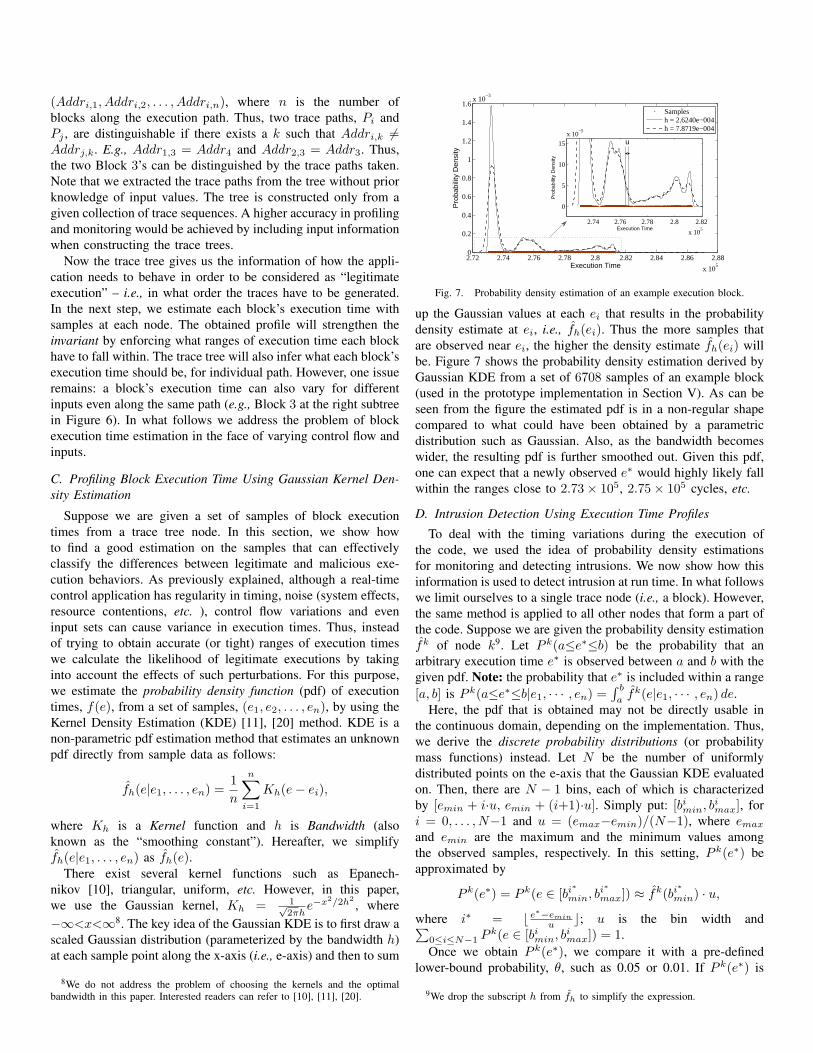
Fig. 7. Probability density estimation of an example execution block.
up the Gaussian values at each ei that results in the probabilitydensity estimate at ei, i.e., fh(ei). Thus the more samples thatare observed near ei, the higher the density estimate fh(ei) willbe. Figure 7 shows the probability density estimation derived byGaussian KDE from a set of 6708 samples of an example block(used in the prototype implementation in Section V). As can beseen from the figure the estimated pdf is in a non-regular shapecompared to what could have been obtained by a parametricdistribution such as Gaussian. Also, as the bandwidth becomeswider, the resulting pdf is further smoothed out. Given this pdf,one can expect that a newly observed e∗ would highly likely fallwithin the ranges close to 2.73× 10⁵, 2.75× 10⁵ cycles, etc.
D. Intrusion Detection Using Execution Time Profiles
To deal with the timing variations during the execution ofthe code, we used the idea of probability density estimationsfor monitoring and detecting intrusions. We now show how thisinformation is used to detect intrusion at run time. In what followswe limit ourselves to a single trace node (i.e., a block). However,the same method is applied to all other nodes that form a part ofthe code. Suppose we are given the probability density estimationfk of node k9. Let P k(a≤e∗≤b) be the probability that anarbitrary execution time e∗ is observed between a and b with thegiven pdf. Note: the probability that e∗ is included within a range[a, b] is P k(a≤e∗≤b|e1, · · · , en) =
∫ b
afk(e|e1, · · · , en) de.
Here, the pdf that is obtained may not be directly usable inthe continuous domain, depending on the implementation. Thus,we derive the discrete probability distributions (or probabilitymass functions) instead. Let N be the number of uniformlydistributed points on the e-axis that the Gaussian KDE evaluatedon. Then, there are N − 1 bins, each of which is characterizedby [emin + i·u, emin + (i+1)·u]. Simply put: [bimin, b
imax], for
i = 0, . . . , N−1 and u = (emax−emin)/(N−1), where emax
and emin are the maximum and the minimum values amongthe observed samples, respectively. In this setting, P k(e∗) beapproximated by
P k(e∗) = P k(e ∈ [bi∗
min, bi∗
max]) ≈ fk(bi∗
min) · u,
where i∗ = ⌊ e∗−emin
u ⌋; u is the bin width and∑0≤i≤N−1 P
k(e ∈ [bimin, bimax]) = 1.
Once we obtain P k(e∗), we compare it with a pre-definedlower-bound probability, θ, such as 0.05 or 0.01. If P k(e∗) is
9We drop the subscript h from fh to simplify the expression.
Core 0 (Monitored Core)LWE
Simics (P4080)
Linux
CC SMDM
SCIOP
Inverted PendulumDynamicsHost PC
Hype
rvisor
Serial (tty) Pseudo Terminal(pts)
Core 1 (Secure Core)Reset Doorbell
Byte Channel
TTM
SPM
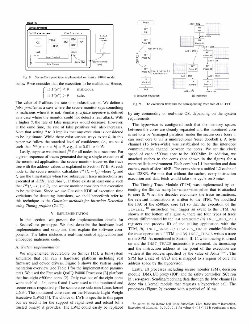
Fig. 8. SecureCore prototype implemented on Simics P4080 model.
below θ we consider that the execution to be malicious. Hence,{if P (e∗) ≤ θ malicious,if P (e∗) > θ safe.
The value of θ affects the rate of misclassification. We define afalse positive as a case where the secure monitor says somethingis malicious when it is not. Similarly, a false negative is definedas a case where the monitor could not detect a real attack. Witha higher θ, the rate of false negatives would decrease. However,at the same time, the rate of false positives will also increases.Note that setting θ to 0 implies that any execution is consideredto be legitimate. While there exist various ways to set θ, in thispaper we follow the standard level of confidence, i.e., we set θsuch that P k(a < e < b) > θ, e.g., θ = 0.01 or 0.05.
Lastly, suppose we obtained fk for all nodes in a trace tree. Fora given sequence of traces generated during a single execution ofthe monitored application, the secure monitor traverses the tracetree with the address values as explained in Section IV-B. At eachnode k, the secure monitor calculates P k(tc − tp) where tp andtc are the timestamps when two subsequent trace instructions areexecuted at Addrp and Addrc. If there exists at least one k suchthat P k(tc−tp) < θk, the secure monitor considers that executionto be malicious. Since we use Gaussian KDE of execution timevariations for detecting intrusions, we shall henceforth refer tothis technique as the Gaussian methods for Intrusion Detectionusing Timing profiles (GaIT).
V. IMPLEMENTATION
In this section, we present the implementation details fora SecureCore prototype. We first describe the hardware-levelimplementation and setup and then explain the software com-ponents. The latter includes a real-time control application andembedded malicious code.
A. System Implementation
We implemented SecureCore on Simics [15], a full-systemsimulator that can run a hardware platform including realfirmware and device drivers. Figure 8 shows the system imple-mentation overview (see Table I for the implementation parame-ters). We used the Freescale QorIQ P4080 Processor [3] platformthat has eight e500mc cores [2]. Only two out of the eight coreswere enabled – i.e., cores 0 and 1 were used as the monitored andsecure cores respectively. The secure core side runs Linux kernel2.6.34. The monitored core runs on the Freescale Light WeightExecutive (LWE) [4]. The choice of LWE is specific to this paperbut we used it for the support of rapid reset and reload (of atrusted binary) it provides. The LWE could easily be replaced
IP Control
FFTInit
FFT Phase #2
FFT Phase #3
Begin
IP Control
FFTInit
FFT Phase #1
FFT Phase #2
FFT Phase #3
End
1 Run if Path ID = 0, 12 Runs if Path ID = 2
Path
ID =
0
Path ID = 1 or 2
FFT Phase #3
IP Control
FFT Phase #1
3.1 3.2 3.3 3.4 3.5 3.6 3.7 3.8 3.9 4
x 105
0
1
2
3
4
5
6x 10
-4
2.65 2.7 2.75 2.8 2.85 2.9
x 105
0
0.2
0.4
0.6
0.8
1
1.2
1.4
1.6
1.8
2x 10
-3
2.72 2.74 2.76 2.78 2.8 2.82 2.84 2.86 2.88
x 105
0
0.2
0.4
0.6
0.8
1
1.2
1.4
1.6x 10
-3
2.5 3 3.5 4 4.5 5 5.5
x 105
0
0.2
0.4
0.6
0.8
1
1.2x 10
-3
1000 1100 1200 1300 1400 1500 1600 17000
0.005
0.01
0.015
0.02
0.025
0.03
0.035
2.589 2.59 2.591 2.592 2.593 2.594 2.595 2.596
x 105
0
1
2
3
4
5
6
7
8x 10
-3
1000 1200 1400 1600 1800 2000 2200 24000
0.005
0.01
0.015
0.02
0.025
0.03
0.035
(a) Execution flow graph (b) Trace tree
Addr = 392
Addr = -3856
Addr = -2916Addr = -2916
Addr = -716
Addr = -1520 Addr = -1520
Addr = 476 Addr = 476
Fig. 9. The execution flow and the corresponding trace tree of IP+FFT.
by any commodity or real-time OS, depending on the systemrequirements.
The hypervisor is configured such that the memory spacesbetween the cores are cleanly separated and the monitored coreis set to a be ‘managed partition’ under the secure core (core 1can reset core 0 via a unidirectional ‘reset doorbell’). A bytechannel (16 bytes-wide) was established to be the inter-corecommunication channel between the cores. We set the clockspeed of each e500mc core to be 1000Mhz. In addition, weattached caches to the cores (not shown in the figure) for amore realistic environment. Each core has L1 instruction and datacaches, each of size 16KB. The cores share a unified L2 cache ofsize 128KB. We note that without the caches, every instructionexecution and data fetch would take one cycle on Simics.
The Timing Trace Module (TTM) was implemented by ex-tending the Simics sample-user-decoder that is attachedto core 0. When the decoder encounters the trace instructions,the relevant information is written to the SPM. We modifiedthe ISA of the e500mc core [2] so that the execution of therlwimi, 10 instruction will trigger an event to the TTM. Asshown at the bottom of Figure 4, there are four types of traceevents differentiated by the last parameter: (a) INST_REG_PIDregisters the process ID of the calling application with theTTM, (b) INST_ENABLE/DISABLE_TRACE enables/disablesthe trace operations of TTM and (c) INST_TRACE writes a traceto the SPM. As mentioned in Section III-C, when tracing is turnedon and the INST_TRACE instruction is executed, the timestampand the instruction address at the point of the execution arewritten at the address specified by the value of AddrHead. TheSPM has a size of 4KB and is mapped to a region of core 1’saddress space by the hypervisor.
Lastly, all processes including secure monitor (SM), decisionmodule (DM), I/O proxy (IOP) and the safety controller (SC) runin user-space. Sending/receiving data through the byte channel isdone via a kernel module that requests a hypervisor call. Theprocesses (Figure 2) execute with a period of 10 ms.
10rlwimi is the Rotate Left Word Immediate Then Mask Insert instruction.Execution of rlwimi 0,0,0,0,i for values 0 ≤ i ≤ 31 is equivalent to nop.
TABLE IIMPLEMENTATION AND EXPERIMENTAL PARAMETERS.Component DescriptionClock speed 1000MHz
L1 Inst. and Data cache 16KB, 8 ways, latency: 2 cyclesL2 Unified cache 128KB, 32 ways, latency: 10 cycles
Exec. time of complex contr. [0.856, 1.26] cyclesExec. times of malicious loops 440, 720, 1000 cycles (1,2,3 loops, resp.)
Lower-bound probability θ 0.01 or 0.05
B. Application Model
As our physical control system, we used an Inverted Pendulum(IP). However, since the simulation speed of Simics is slowerby an order of magnitude than the dynamics of a real IP,we used control code and related dynamics generated from aSimulink [25] IP model. These were then encapsulated intosoftware processes. The dynamics process runs on the host PCand is synchronized with the control system managing it inSimics through a pseudo terminal (Note: Simics sees it as a realserial connection). The physical state of IP is defined as the cartposition and the rod’s angle, perpendicular to the ground. Thisstate is sent to the controllers executing on Simics and they, inturn, compute an actuation command that is then sent back tothe dynamics process that then emulates the action of the IP. Forrealistic dynamics, we embedded a Gaussian noise generator atthe output of the rod angle in the dynamics.
As mentioned above, the system runs on Simics and and mon-itors the IP control application. We use the same control code forthe complex and simple controllers for evaluation purpose only.However, since the code is too simple with very little variancein execution time, we inserted a fast fourier transform (FFT)benchmark from the EEMBC AutoBench suite [9], aifft, tothe complex controller as shown in Figure 9 (a). The benchmarkconsists of three phases after initialization. We modified it sothat after initialization it randomly selects a path ID. If the IDis ‘0’, FFT Phase 2 is skipped, and Phase 3 is executed twice ifthe ID is ‘2’. From this structure, we wish to observe how wellour detection methods can deal with execution time variancescaused by inputs and flows. After the FFT phases complete, theIP control logic is executed. The logic controls the IP so that itis kept stabilized at position ‘+1’ meter from the origin.
We inserted “malicious code” at the end of FFT Phase 3. It is asmall loop in which some arrays used in previous FFT phases arecopied. The average execution time of the malicious code is 440,720 and 1000 cycles for 1, 3 and 5 loops respectively. The codebecomes activated when the cart position of IP received from IOPbecomes +0.7 meter. Thereafter the code is executed randomlyand the complex controller discards the actuation commandcalculated by the IP logic and sends out one duplicated from theprevious execution. This will result in two effects – variances inexecution time that differ from expected values and also sendswrong actuation information to the control system. Both of theseeffects should trigger our detection systems.
To profile the execution times of the complex controller, weinserted INST_TRACE instructions at the end of each blockand one at the top of each ‘flow’ (i.e., before FFT init()) asexplained in Section IV-B. We executed the system in a normalcondition (i.e., no malicious code activation) for 10, 000 runsuntil we obtained a collection of traces. From these traces, a trace
0 5 10 15 20 25 300
0.1
0.2
0.3
0.4
0.5
0.6
0.7
0.8
0.9
1
1.1
1.2
Time (sec)
Car
t pos
ition
(m
eter
)
6 8 10 12 14 16
0.6
0.7
0.8
0.9
1
1.1
Simplex Only
Attack Activated
Simplex Only
No Attack
No Protection
No AttackAttack Activated
GaIT
GaIT
Fig. 10. Trajectory of cart with different protection approaches.
tree is constructed as shown in Figure 9 (b). We then used theksdensity function 11 in Matlab to derive the pdf estimationfk of the samples at each block k.
VI. RESULT AND DISCUSSION
In this section, we evaluate our SecureCore architecturethrough experiments on the prototype presented in Section V. Wethen present some limitations and discuss possible improvements.
A. Early Detection of an Intrusion
We first evaluate our timing-based intrusion detection methodby measuring how quickly it can detect malicious code executioncompared to vanilla Simplex-only approach. As explained inSection V-B, the malicious code embedded in the complexcontroller is activated when the cart passes through the pointat +0.7 m. In this evaluation, we set the lower-bound probabilityθ to 0.01 and the loop count of the malicious code to 3.
The cart positions were traced from the IP dynamics processfor the cases where (a) there is no attack, (b) attack + noprotection, (c) attack + Simplex only and finally (d) attack +Simplex + GaIT (our detection method). Additionally, we setan event that is triggered when Simplex or our method detectanomalies. However, for evaluation purposes, we intentionallydisabled our method until the cart passes over +0.5 meter; if weenable it from the beginning, a false positive would activate thesafety controller before an attack takes place.
Figure 10 shows the different trajectories of the cart for thefour cases. The cart is stabilized at the position near +1m whenthere is no attack or if the control logic is protected (eitherby GaIT or vanilla Simplex). When there is no such protectionmechanism however, the cart becomes destabilized finally aftertime 25 seconds. When the protection mechanisms are active(SecureCore + GaIT) and the malicious code was activated (ataround 6.9 seconds), it was almost instantly detected by GaIT.We can see this from the magnified section of the plot showingthe trajectory of the cart along with the normal case (i.e., noattack). On the other hand, although it is not clear in the figure,the ‘Simplex only’ method detected the abnormal behavior ofthe complex controller at around 9.5 seconds. In this case, wesee that the cart has deviated from its normal trajectory for amoment; it was later returned to the normal trajectory. Eventhough the experiment was performed with a restrictive setup
11We set the number of bins, N , to 1000. The kernel smoothing bandwidth his then automatically selected by the function.
1 3 50
0.1
0.2
0.3
0.4
0.5
0.6
0.7
0.8
0.9
1
Malicious loop count
Rat
e of
fal
se n
egat
ive
θ=0.01 θ=0.05
Fig. 11. False negative rates for different θ and malicious loop counts.
for a simple application, the result shows that our timing-profilebased intrusion detection method (GaIT) can supplement Simplexthrough early detection. Even though vanilla Simplex can detectmalicious activity, it does so much later than GaIT and onlybecause the compromised controller tried to actuate the physicalsystem into an unsafe state. Many times, attackers may not sendwrong actuation commands – they may snoop on the operationof the system and collect privileged information. SecureCore andGaIT will be able to detect such activity almost instantaneously,as evidenced here, while Simplex will fail to detect it. Also,attackers could increase the wear and tear on the physical systemunder vanilla Simplex – by causing the system to operate, albeitbriefly, in an unsafe state. This can also be avoided by use ofour techniques.
B. Intrusion Detection Accuracy
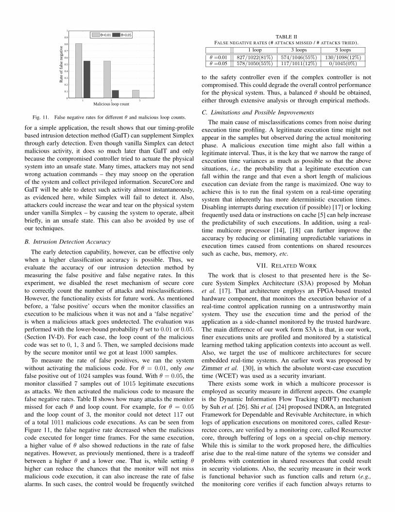
The early detection capability, however, can be effective onlywhen a higher classification accuracy is possible. Thus, weevaluate the accuracy of our intrusion detection method bymeasuring the false positive and false negative rates. In thisexperiment, we disabled the reset mechanism of secure coreto correctly count the number of attacks and misclassifications.However, the functionality exists for future work. As mentionedbefore, a ‘false positive’ occurs when the monitor classifies anexecution to be malicious when it was not and a ‘false negative’is when a malicious attack goes undetected. The evaluation wasperformed with the lower-bound probability θ set to 0.01 or 0.05.(Section IV-D). For each case, the loop count of the maliciouscode was set to 0, 1, 3 and 5. Then, we sampled decisions madeby the secure monitor until we got at least 1000 samples.
To measure the rate of false positives, we ran the systemwithout activating the malicious code. For θ = 0.01, only onefalse positive out of 1024 samples was found. With θ = 0.05, themonitor classified 7 samples out of 1015 legitimate executionsas attacks. We then activated the malicious code to measure thefalse negative rates. Table II shows how many attacks the monitormissed for each θ and loop count. For example, for θ = 0.05and the loop count of 3, the monitor could not detect 117 outof a total 1011 malicious code executions. As can be seen fromFigure 11, the false negative rate decreased when the maliciouscode executed for longer time frames. For the same execution,a higher value of θ also showed reductions in the rate of falsenegatives. However, as previously mentioned, there is a tradeoffbetween a higher θ and a lower one. That is, while setting θhigher can reduce the chances that the monitor will not missmalicious code execution, it can also increase the rate of falsealarms. In such cases, the control would be frequently switched
to the safety controller even if the complex controller is notcompromised. This could degrade the overall control performancefor the physical system. Thus, a balanced θ should be obtained,either through extensive analysis or through empirical methods.
C. Limitations and Possible Improvements
The main cause of misclassifications comes from noise duringexecution time profiling. A legitimate execution time might notappear in the samples but observed during the actual monitoringphase. A malicious execution time might also fall within alegitimate interval. Thus, it is the key that we narrow the range ofexecution time variances as much as possible so that the abovesituations, i.e., the probability that a legitimate execution canfall within the range and that even a short length of maliciousexecution can deviate from the range is maximized. One way toachieve this is to run the final system on a real-time operatingsystem that inherently has more deterministic execution times.Disabling interrupts during execution (if possible) [17] or lockingfrequently used data or instructions on cache [5] can help increasethe predictability of such executions. In addition, using a real-time multicore processor [14], [18] can further improve theaccuracy by reducing or eliminating unpredictable variations inexecution times caused from contentions on shared resourcessuch as cache, bus, memory, etc.
VII. RELATED WORK
The work that is closest to that presented here is the Se-cure System Simplex Architecture (S3A) proposed by Mohanet al. [17]. That architecture employs an FPGA-based trustedhardware component, that monitors the execution behavior of areal-time control application running on a untrustworthy mainsystem. They use the execution time and the period of theapplication as a side-channel monitored by the trusted hardware.The main difference of our work form S3A is that, in our work,finer executions units are profiled and monitored by a statisticallearning method taking application contexts into account as well.Also, we target the use of multicore architectures for secureembedded real-time systems. An earlier work was proposed byZimmer et al. [30], in which the absolute worst-case executiontime (WCET) was used as a security invariant.
There exists some work in which a multicore processor isemployed as security measure in different aspects. One exampleis the Dynamic Information Flow Tracking (DIFT) mechanismby Suh et al. [26]. Shi et al. [24] proposed INDRA, an IntegratedFramework for Dependable and Revivable Architecture, in whichlogs of application executions on monitored cores, called Resur-rectee cores, are verified by a monitoring core, called Resurrectorcore, through buffering of logs on a special on-chip memory.While this is similar to the work proposed here, the difficultiesarise due to the real-time nature of the sytems we consider andproblems with contention in shared resources that could resultin security violations. Also, the security measure in their workis functional behavior such as function calls and return (e.g.,the monitoring core verifies if each function always returns to
the right address). We focus on the execution profiles of thetasks (e.g., timing) as security invariants – something that is veryfeasible in real-time systems but not in general purpose ones.
Similar work can be found in [6] by Chen et al. The workalso employs a logging hardware that captures the information,e.g., program counter, input and output operands and memoryaccess addresses of any instruction that the monitored applicationexecutes. The captured traces are delivered through a cache toanother core for inspection. The work was extended to [7], wherea hardware accelerator was proposed to reduce high overheads ininstruction-grain monitoring. There have also been coprocessor-based approaches. In [12], Kannan et al. addressed the highoverheads in the multicore-based DIFT by proposing the DIFTCo-processor, in which application instructions and memoryaccess addresses, etc., are checked with a pre-defined securitypolicy. A similar approach was taken in [8] by Deng et al.where reconfigurable logic attached to the main CPU checkedfor software error as well as DIFT from execution traces.
All of these techniques, while applicable for general pur-pose systems, could also be repurposed for embedded real-timesystems. Hence, the combination of these techniques with outSecureCore and GaIT approaches will only make the overallsystem more secure and hence, safer.
VIII. CONCLUSION
In this paper, we proposed SecureCore, a novel applicationof a multicore processor for creating a secure and reliable real-time control system. We used a statistical learning method forprofiling and monitoring the execution behavior of a controlapplication (GaIT). Through the architectural and the theoreticalsupport, our intrusion detection mechanism implemented coulddetect violations earlier than just a pure safety-driven method,Simplex. This helps in achieving reliable control for physicalsystems. This method also prevents attackers from causing harmto the physical systems, even if they gain total control of themain controller. The isolation achieved by SecureCore and themonitoring mechanisms presented by GaIT will prevent from thephysical system from being harmed. Evaluation results showedthat with careful analysis and design of certain parameters, onecan achieve a low misclassification rate and higher (intrusion)detection rates. As future work, we plan to extend the presentedapproach to support concurrent monitoring of multiple applica-tions on multiple cores.
[5] A. Arnaud and I. Puaut. Dynamic instruction cache locking in hard real-time systems. In Proc. of the 14th International Conference on Real-Timeand Network Systems (RNTS), May 2006.
[6] S. Chen, B. Falsafi, P. B. Gibbons, M. Kozuch, T. C. Mowry, R. Teodorescu,A. Ailamaki, L. Fix, G. R. Ganger, B. Lin, and S. W. Schlosser. Log-based architectures for general-purpose monitoring of deployed code. InProceedings of the 1st workshop on Architectural and system support forimproving software dependability, pages 63–65, 2006.
[7] S. Chen, M. Kozuch, T. Strigkos, B. Falsafi, P. B. Gibbons, T. C. Mowry,V. Ramachandran, O. Ruwase, M. Ryan, and E. Vlachos. Flexible hardwareacceleration for instruction-grain program monitoring. In Proceedings of the35th Annual International Symposium on Computer Architecture, ISCA ’08,pages 377–388, 2008.
[8] D. Y. Deng, D. Lo, G. Malysa, S. Schneider, and G. E. Suh. Flexible and ef-ficient instruction-grained run-time monitoring using on-chip reconfigurablefabric. In Proceedings of the 2010 43rd Annual IEEE/ACM InternationalSymposium on Microarchitecture, pages 137–148, 2010.
[9] EEMBC AutoBench Suite. http://www.eembc.org.[10] V. A. Epanechnikov. Non-Parametric Estimation of a Multivariate Proba-
bility Density. Theory Probab. Appl, 14(1):153–158, 1969.[11] M. C. Jones, J. S. Marron, and S. J. Sheather. A Brief Survey of Bandwidth
Selection for Density Estimation. Journal of the American StatisticalAssociation, 91(433):401–407, 1996.
[12] H. Kannan, M. Dalton, and C. Kozyrakis. Decoupling dynamic informationflow tracking with a dedicated coprocessor. In Proceedings of the 43thAnnual IEEE/IFIP International Conference on Dependable Systems andNetworks, DSN ’09, pages 105–114, 2009.
[13] K. Koscher, A. Czeskis, F. Roesner, S. Patel, T. Kohno, S. Checkoway,D. McCoy, B. Kantor, D. Anderson, H. Shacham, and S. Savage. Experi-mental security analysis of a modern automobile. In Security and Privacy(SP), 2010 IEEE Symposium on, pages 447 –462, may 2010.
[14] B. Lickly, I. Liu, S. Kim, H. D. Patel, S. A. Edwards, and E. A. Lee.Predictable Programming on a Precision Timed Architecture. In Proc. ofInt’l Conference on Compilers, Architecture, and Synthesis from EmbeddedSystems, 2008.
[15] P. S. Magnusson, M. Christensson, J. Eskilson, D. Forsgren, G. Hllberg,J. Hgberg, F. Larsson, A. Moestedt, and B. Werner. Simics: A full systemsimulation platform. Computer, 35:50–58, 2002.
[16] W. mei W. Hwu, S. A. Mahlke, W. Y. Chen, P. P. Chang, N. J. Warter, R. A.Bringmann, R. G. Ouellette, R. E. Hank, T. Kiyohara, G. E. Haab, J. G.Holm, and D. M. Lavery. The superblock: An effective technique for vliwand superscalar compilation. The Journal of Supercomputing, 7:229–248,1993.
[17] S. Mohan, S. Bak, E. Betti, H. Yun, L. Sha, and M. Caccamo. S3A:Secure system simplex architecture for enhanced security of cyber-physicalsystems. CoRR, abs/1202.5722, 2012.
[18] M. Paolieri, E. Quinones, F. J. Cazorla, G. Bernat, and M. Valero. HardwareSupport for WCET Analysis of Hard Real-Time Multicore Systems. InProc. of IEEE/ACM Int’l Symposium on Computer Architecture, pages 57–68, 2009.
[19] P. Parkinson. Safety, security and multicore. In Proceedings of 19th Safety-Critical Systems Symposium, pages 215–232, 2011.
[20] E. Parzen. On Estimation of a Probability Density Function and Mode. TheAnnals of Mathematical Statistics, 33(3):1065–1076, 1962.
[21] M. Schoeberl and P. Puschner. Is Chip-Multiprocessing the End of Real-Time Scheduling? In Proc. of Int’l Workshop on Worst-Case ExecutionTime (WCET) Analysis, 2009.
[22] L. Sha. Using simplicity to control complexity. IEEE Softw., 18(4):20–28,2001.
[23] D. Shepard, J. Bhatti, and T. Humphreys. Drone hack: Spoofing attackdemonstration on a civilian unmanned aerial vehicle. GPS World, August2012.
[24] W. Shi, H.-H. S. Lee, L. ‘Falk, and M. Ghosh. An integrated frameworkfor dependable and revivable architectures using multicore processors. InProceedings of the 33rd annual international symposium on ComputerArchitecture, ISCA ’06, pages 102–113, 2006.
[25] Simulink. http://www.mathworks.com/products/simulink.[26] G. E. Suh, J. W. Lee, D. Zhang, and S. Devadas. Secure program
execution via dynamic information flow tracking. In Proceedings of the11th international conference on Architectural support for programminglanguages and operating systems, ASPLOS-XI, pages 85–96, 2004.
[27] US-CERT. ICSA-10-272-01: Primary stuxnet indicators. Aug. 2010.[28] P. Wilson, A. Frey, T. Mihm, D. Kershaw, and T. Alves. Implementing
[29] S. Zhuravlev, S. Blagodurov, and A. Fedorova. Addressing Shared ResourceContention in Multicore Processors via Scheduling. In Proc. of Int’lConference on Architectural Support for Programming Languages andOperating Systems, pages 129–142, 2010.
[30] C. Zimmer, B. Bhatt, F. Mueller, and S. Mohan. Time-based intrusiondetection in cyber-physical systems. In International Conference on Cyber-Physical Systems, 2010.