C • CURE 800 and 8000 Enterprise Systems •••••••••••••••••••••••••••••••••••••••••••••••••••••• Security Management Control System Engineering Specification Version 10.3.0 Revised July 2012 Software House makes no representations or warranties with respect to the contents hereof and specifically disclaims any implied warranties of merchantability or fitness for any particular purpose. Furthermore, Software House reserves the right to revise this publication from time to time in the content hereof without the obligation to notify any person of any such revision or changes. NOTE: The specifier should carefully select the portions of this document that fit the intended application. Feel free to consult with Software House regarding your particular application. For information or assistance, call Software House at (978) 577-4000 or 800-507-6268 (select option 3, and then option 2) .
Engineering Specification Version 10.3.0 Revised July 2012
Software House makes no representations or warranties with respect to the contents hereof and specifically disclaims any implied warranties of merchantability or fitness for any particular purpose. Furthermore, Software House reserves the right to revise this publication from time to time in the content hereof without the obligation to notify any person of any such revision or changes.
NOTE: The specifier should carefully select the portions of this document that fit the intended application. Feel free to consult with Software House regarding your particular application.
For information or assistance, call Software House at (978) 577-4000 or 800-507-6268 (select option 3, and then option 2) .
2.1 Manufacturers _____________________________________________________________ 5 2.1.1 Security Management Control System Software ................................................................................... 5 2.1.2 Security Management Control System Field Hardware ......................................................................... 5
2.2 Server Configuration _________________________________________________________ 5 2.2.1 Minimum CPU Capacities ....................................................................................................................... 5 2.2.2 High Resolution Graphics ....................................................................................................................... 6 2.2.3 Information Storage ............................................................................................................................... 6 2.2.4 Information Backup/Retrieval................................................................................................................ 6 2.2.5 Communications Rates .......................................................................................................................... 6 2.2.6 Printers................................................................................................................................................... 7 2.2.7 Mouse .................................................................................................................................................... 7 2.2.8 Communication Ports ............................................................................................................................ 7 2.2.9 Encryption .............................................................................................................................................. 8 2.2.10 Redundant Array of Independent Disks (RAID) ................................................................................. 8 2.2.11 Symmetric Multiprocessor (SMP) Support ........................................................................................ 9 2.2.12 Redundancy ...................................................................................................................................... 9
2.3 Operator Workstations _______________________________________________________ 9 2.3.1 Minimum CPU Capacities ....................................................................................................................... 9 2.3.2 Local Area Network .............................................................................................................................. 10
2.8 Area Lockout (iSTAR) _______________________________________________________ 84 2.8.1 General ................................................................................................................................................ 84 2.8.2 Definition ............................................................................................................................................. 85 2.8.3 LCD Display .......................................................................................................................................... 86 2.8.4 Monitoring Station ............................................................................................................................... 86 2.8.5 Journal ................................................................................................................................................. 86
2.9 Intrusion Zones ____________________________________________________________ 86 2.9.1 General ................................................................................................................................................ 86 2.9.2 Intrusion Zone Definition ..................................................................................................................... 87
2.17 Central System Monitoring _________________________________________________ 117 2.17.1 General .......................................................................................................................................... 117
2.17.2 Configuration ................................................................................................................................ 117 2.17.3 Login .............................................................................................................................................. 118 2.17.4 Logout ........................................................................................................................................... 118 2.17.5 Status Screen ................................................................................................................................. 119 2.17.6 Manual Actions ............................................................................................................................. 119 2.17.7 Privileges ....................................................................................................................................... 119 2.17.8 Time Zones .................................................................................................................................... 119 2.17.9 Name ............................................................................................................................................. 119 2.17.10 Group Handling ............................................................................................................................. 119 2.17.11 Badge Images ................................................................................................................................ 120 2.17.12 Maps ............................................................................................................................................. 120 2.17.13 Event Sounds ................................................................................................................................. 120 2.17.14 Expiration ...................................................................................................................................... 120 2.17.15 Two Phase Acknowledgement for Central Monitoring ................................................................. 120
2.18 Alarm Routing ____________________________________________________________ 121 2.18.1 General .......................................................................................................................................... 121 2.18.2 Set Server Connections ................................................................................................................. 121 2.18.3 Last User Log Out .......................................................................................................................... 121 2.18.4 Reports .......................................................................................................................................... 122
2.23 Threat Level ______________________________________________________________ 142 2.23.1 General .......................................................................................................................................... 142
2.24 Clearance Filter ___________________________________________________________ 143 2.24.1 General .......................................................................................................................................... 143
2.25 Incident ID _______________________________________________________________ 143 2.25.1 General .......................................................................................................................................... 143
2.26 Display Personnel Browser without Card Number and Person ID ___________________ 144 2.26.1 General .......................................................................................................................................... 144
2.27 Automated Import Enhancements ____________________________________________ 144 2.27.1 General .......................................................................................................................................... 144
2.28 Installation of C•CURE 800/8000 Using the Client MSI ___________________________ 144 2.28.1 General .......................................................................................................................................... 144
2.29 iSTAR eX Support and Encryption ____________________________________________ 145 2.29.1 General .......................................................................................................................................... 145
2.30 After Hours Enabling Reader ________________________________________________ 145 2.30.1 General .......................................................................................................................................... 145
3.1 Access Control System - Installation __________________________________________ 145 3.1.1 General .............................................................................................................................................. 145 3.1.2 Installation ......................................................................................................................................... 145 3.1.3 Device Wiring and Communication Circuit Surge Protection ............................................................ 145
3.2 Training _________________________________________________________________ 146 3.2.1 General .............................................................................................................................................. 146
3.3 Testing __________________________________________________________________ 146 3.3.1 General .............................................................................................................................................. 146 3.3.2 Performance Verification Test ........................................................................................................... 146
3.4 Warranty, Maintenance and Service __________________________________________ 146 3.4.1 Warranty ............................................................................................................................................ 146 3.4.2 Maintenance and Service................................................................................................................... 146 3.4.3 Description of Work ........................................................................................................................... 147 3.4.4 Personnel ........................................................................................................................................... 147 3.4.5 Inspections ......................................................................................................................................... 147 3.4.6 Emergency Service ............................................................................................................................. 147 3.4.7 Software ............................................................................................................................................. 147
This document includes a general description, functional requirements, characteristics, and criteria for the Security Management Control System.
This specification provides all information necessary to produce a complete proposal for a sophisticated, easy-to-use, multi-tasking, multi-user Security Management Control System (SMCS). The SMCS shall include all computer hardware and software, intelligent field advanced processing controller (apC/ L/ 8X and iSTAR), communication devices, card readers/ keypads, access cards, I/ O boards, power supplies, conduit, raceways, enclosures, mounting hardware, and all other equipment as indicated on the contract drawings and as specified herein. A ll material shall be the manufacturer’s standard catalog products.
1.1 General Description The required Security Management Control System shall be a powerful, multi-function security and access management system.
It shall operate in a Client/ Server configuration on high-quality IBM compatible Pentium processor personal computers (PC).
The Server (Host) PC, shall have a Pentium 600 to 1.5 GHz central processor. The Client (Operator workstation) PC(s) shall have a Pentium 400 or greater central processor. The exact hardware configurations shall be described in a later section of this specification.
The Security Management Control System shall be designed to grow as project needs grow. The system shall be simple and economical enough to support a single site, yet powerful enough to manage a multi-site network.
The system shall have true multi-tasking and remote terminal capability; independent activities and monitoring can occur simultaneously at different locations. The Operator workstation (Client) shall be very easy to use. It shall employ icon-based menus and provide a mouse-driven interface for system operation and the creation of color graphic maps.
The Security Management Control System shall be designed to support Software House’s full line of distributed processing based controllers.
A ll objects within the system, i.e., Doors, Readers, Time Intervals, etc., shall be addressed by a unique name. The uses of point numbering or mnemonics shall not be accepted.
Field devices, such as card readers, alarm inputs, control points, etc., shall be connected to fully distributed intelligent field controllers (apC/ 8X/ 8X and iSTAR) capable of operating without host computer intervention.
1.2 Description of Work The Security Management Control System shall manage the security operations for a single site or for multiple sites. Installing the SMCS and bringing it to operational status requires the following major steps:
• Determine operational requirements and plan system to implement them.
• Select host computer site.
• Install and configure, where necessary, the communications network providing communications between the Client and Server computer workstation.
• Install and integrate Access Control, A larm Monitoring and related security hardware.
• Configure local access panels and SMCS Server computer system to communicate with one another.
• Enter security system database.
• Connect between host system, access controllers, and related hardware.
• Test security system communication and operation.
• Train operators.
1.3 Submittals
1.3.1 Shop Drawings Provide complete shop drawings which include the following:
• Indicate all system device locations on architectural floor plans. No other system(s) shall be included on these plans.
• Include full schematic wiring information on these drawings for all devices. Wiring information shall include cable type, conductor routings, quantities, and connection details at devices.
• Include a complete access control system one-line, block diagram.
• Include a statement of the system sequence of operation.
1.3.2 Product Data Provide complete product data that includes the following:
• Manufacturer’s data for all material and equipment, including terminal devices, local processors, computer equipment, access cards, and any other equipment provided as part of the SMCS.
• A system description, including analysis and calculations used in sizing equipment required by the SMCS.
• A description to show how the equipment shall operate as a system to meet the performance requirements of the SMCS.
• The following information shall be supplied as a minimum:
• Central processor configuration and memory size
• Description of site equipment and its configuration
• System expansion capability and method of implementation
• System power requirements and UPS sizing • A description of the operating system and application software.
1.3.3 Contract Close-Out Submittals Provide three (3) sets of manuals including operating instructions, maintenance recommendations and parts list including wiring and connection diagrams modified to reflect as-built conditions.
1.3.4 Manuals Final copies of the manuals shall be delivered within thirty (30) days after completing the installation test. Each manual’s contents shall be identified on the cover. The manual shall include names, addresses, and telephone numbers of each security system integrator installing equipment and systems and the nearest service representatives for each item of equipment for each system. The manuals shall have a table of contents and labeled sections. The final copies delivered after completion of the installation test shall include all modifications made during installation, checkout, and acceptance. The manuals shall contain the following:
1.3.4.1 Functional Design M anual The functional design manual shall identify the operational requirements for the system and explain the theory of operation, design philosophy, and specific functions. A description of hardware and software functions, interfaces, and requirements shall be included for all system operating modes.
1.3.4.2 Hardware M anual The manual shall describe all equipment furnished including: • General description and specifications • Installation and check out procedures • Equipment layout and electrical schematics to the component level • System layout drawings and schematics • A lignment and calibration procedures • Manufacturers repair parts list indicating sources of supply
1.3.4.3 Software M anual The software manual shall describe the functions of all software and shall include all other information necessary to enable proper loading, testing, and operation. The manual shall include: • Definition of terms and functions • Use of system and applications software • Initialization, start up, and shut down • A larm reports • Reports generation
• Data base format and data entry requirements • Directory of all disk files
1.3.4.4 Operators M anual The operator’s manual shall fully explain all procedures and instructions for the operation of the system including:
• Computers and peripherals • System start up and shut down procedures • Use of system, command, and applications software • Recovery and restart procedures • Graphic alarm presentation • Use of report generator and generation of reports • Data entry • Operator commands • A larm messages and reprinting formats • System access requirements
1.3.4.5 M aintenance M anual The maintenance manual shall include descriptions of maintenance for all equipment including inspection, periodic preventive maintenance, fault diagnosis, and repair or replacement of defective components.
1.3.5 As-Built Drawings During system installation, the Contractor shall maintain a separate hard copy set of drawings, elementary diagrams, and wiring diagrams of the SMCS to be used for record drawings. This set shall be accurately kept up to date by the Contractor with all changes and additions to the SMCS. In addition to being complete and accurate, this set of drawings shall be kept neat and shall not be used for installation purposes. Copies of the final as-built drawings shall be provided to the end user in DXF format using the latest version of AutoCAD.
1.4 Quality Assurance The manufacturers of all hardware and software components employed in the system shall be established vendors to the access control/ security monitoring industry for no less than five (5) years.
The security system integrator shall have been regularly engaged in the installation and maintenance of integrated access control systems similar in size and scope to that outlined herein for a period of no less than five (5) years.
The security system integrator shall supply information attesting to the fact that their firm is an authorized product dealer for the system proposed.
The security system integrator shall supply information attesting to the fact that their installation and service technicians are competent factory trained personnel capable of maintaining the system and providing reasonable service time.
The security system integrator shall provide a minimum of three (3) references whose systems are of similar complexity and have been installed and maintained by the security system integrator in the last five (5) years.
There shall be a local representative and factory authorized local service organization that shall carry a complete stock of parts and provide maintenance for these systems. Local shall be defined as an area in a [ ] mile radius of installed location.
1.5 Warranty The following changes to the Warranty terms take effect May 11, 2000:
• The Warranty on C•CURE 800/ 8000 bundled system packages and software only packages will be 14 months from the date of shipment, or 1 year from date of registration, whichever is shorter. Under the terms of the warranty, version upgrades are available “ at no extra charge” only if the customer is under a valid warranty or valid SSA. Bug fix releases will be made available to all customers under a valid warranty or SSA (critical bugs excluded). Refer to the SSA Entitlements in the price book for specific details
• The software warranty will now be activated at the time of installation assuming the Software License Registration has been completed and is on file at Software House.
• Before May 11, 2000, the previous terms of the Warranty shall apply, that is, the warranty for all unbundled (software only) packages will be 90 days from date of installation, and the warranty on bundled system packages will remain 14 months from the date of shipment, or 1 year from date of registration, whichever is shorter.
2.1.1 Security M anagement Control System Software Software House C•CURE 800/ 8000 System
2.1.2 Security M anagement Control System Field Hardware Software House apC/ L/ 8X and iSTAR controllers
2.2 Server Configuration
2.2.1 Minimum CPU Capacities The Server CPU shall be 100% IBM compatible Pentium PC approved for running the Microsoft Windows XP (32-bit), Windows 2003 (32-bit), Windows Vista (32-bit), Windows 2008 (32-bit), Windows 2008 R2 (64-bit supported on Standard or Enterprise platforms only) or Windows 7 (32-bit and 64-bit Supported on Professional and Enterprise platforms only) operating systems. The PC shall have the following minimum configuration dependent upon system capacities:
• 1 -2 GB RAM (based on model) (Windows 7 and Windows 2008 R2 require 2 GB)
• Two (2) serial ports (optional for communicating to serial devices)
• PS/ 2 or USB style mouse
• Windows XP, 2003, Vista, Windows 7 or 2008 operating system
• Ethernet Adapter
• Display Adapter (1024 x 768 resolution @ 65,536 colors)
• 56.6K baud modem (optional)
2.2.2 High Resolution Graphics The system shall support a minimum of 200 user programmable color graphic map displays capable of showing the floor plan, location of alarm device, and alarm instructions. Floor plans shall be created in a .PCX or .BMP format and shall be capable of being imported from other systems. The system shall provide the ability to drop dynamic object icons onto the drawings. These dynamic object icons shall allow the system operator to perform tasks/ issue commands related to the object, by double clicking on the icon. A ll of the graphic maps are to be centralized in the system configuration and shall be displayed on the operator’s workstations. Systems requiring separate display monitors or PC are not acceptable.
2.2.3 Information Storage All programmed information as well as transactional history shall be automatically stored onto the server hard disk for later retrieval. The system shall warn the operator when the disk space allocation approaches maximum capacity. The system shall allow the system administrator to determine at what percentage of capacity the warnings shall be issued. The system shall further allow the system administrator to define the frequency at which the warnings shall be issued to system operators.
2.2.4 Information Backup/Retrieval The Server CPU shall be capable of transferring all programmed data and transactional history to a DVD or external hard drive. A ll programmed data shall be restorable from a DVD or external hard drive in case of system hardware failure. A lso, see Automated Backup on page 148.
2.2.5 Communications Rates The system shall be capable of supporting a communication rate of 19,200 baud to all access control panels and 10/ 100MB Ethernet communications rates to client workstations and Network connected controllers.
2.2.6 Printers The SMCS shall support report printers. The report printers may be connected to the parallel port of the Server or Client computers.
2.2.7 Mouse The SMCS shall only utilize a mouse as the man - machine interface. The mouse shall be used throughout the application.
2.2.8 Communication Ports
2.2.8.1 Serial ports The SMCS shall be able to support multiple serial devices. In addition to COM1 and COM2, up to [8, 16, 32, to 256] additional ports may be configured through the use of a port expander as manufactured by DigiBoard or equal. These serial ports may be used for connection to apC/ L/ 8X field panels, modems and CCTV matrix switchers.
The SMCS shall support up to two hundred and fifty six ports for communication to the apC/ 8Xs. A maximum of [16, 32, 128, 256] apC/ 8Xs may be configured per system. In a hardwired configuration up to sixteen (16) apC/ L/ 8Xs may be configured per line.
2.2.8.2 Network ports The SMCS shall support the use of Ethernet networks as the communications path between the host computer and field devices such as modems, apC/ L/ 8X and iSTAR controllers, and CCTV matrix switchers. This communications path shall be the same network used for communications between the host server and the operator workstations. The communications between the host computer and the field devices shall be encapsulated in a TCP/ IP network/ transport layer. In a dedicated network configuration, up to six (6) apC/ L/ 8X may be configured per line.
2.2.8.3 Port name Each communications port shall be addressed with the system by a unique fifty (50) character user defined name. The use of code numbers or mnemonics shall not be accepted.
2.2.8.4 Port description The system shall provide the ability to add a communication port description to each port configuration. The maximum amount of characters that can be used to describe the communication port is three-thousand (3,000).
2.2.8.5 On-line/Off-line The system shall allow the operator to put a communications port on-line or off-line. If the communications port is placed off-line, the system shall not use the port to communicate to field devices configured on that port. If the communications port is put on-line, the system shall use the port to communicate to field devices configured on that port.
2.2.8.6 Communications failure If the communications port is on a network device, such as a terminal server, the system shall indicate if there is a loss of communications to that network address. A ll field units connected to that network address should also be reported as being in communications failure.
To allow for network delays, the system shall allow the system administrator to define a wait time before annunciation of a communications failure. The wait time shall be from zero (0) to ninety-nine (99) in one-tenth (1/ 10) second increments.
The system shall provide the administrator the ability to set a reconnect retry period. This is the time period the system shall wait before attempting to re-establish communications with a network port which is in communications failure. The reconnect retry period shall be from zero (0) to ninety-nine (99) in one-tenth (1/ 10) second increments.
Configuration of the remote communications port characteristics, i.e. baud rate, parity, error-checking etc. shall be done either on the network device or through network management tools. This configuration is not required to be executed by the Security Management Control System.
2.2.8.7 IP address For communications ports on a network device, the system shall allow the operator to define the IP address of the device, as well as the local port address, to which the remote field devices are connected.
2.2.9 Encryption It shall be possible to configure a system such that the communications between the Host computer and the apC/ L/ 8X panel or iSTAR controller is encrypted.
2.2.10 Redundant Array of Independent Disks (RAID) The system shall support a redundant array of multiple independent hard disk drives (RAID) that provide high performance and fault tolerance. The RAID array shall appear to the host computer as a single storage unit or as multiple logical units.
2.2.10.1 RAID 1 The system shall support the use of RAID level 1. RAID level 1 provides complete data redundancy.
2.2.10.2 RAID 5 The system shall support the use of RAID level 5. RAID level 5 includes disk striping at the block level and parity.
2.2.11 Symmetric Multiprocessor (SMP) Support The system shall have the ability to support two or more processors in one PC.
2.2.12 Redundancy Through the use of third-party software and associated hardware, the system shall support a second server for redundant capability. During normal operation, data shall be written to either server and shall be mirrored to its counterpart in a bi-directional mirroring process.
If a failure is detected, it shall be verified across both the network and the mirrored data links. When the failure has been verified, the surviving server shall assume the functions and identities of the failed server without having to sacrifice its own identities or functions. Applications originally running on the failed server are restarted on the surviving server.
2.3 Operator Workstations
2.3.1 Minimum CPU Capacities • The Operator (Client) workstation shall be 100% IBM compatible Pentium PC
approved for running the Microsoft Windows XP (32-bit), Windows 2003 (32-bit), Windows Vista (32-bit), Windows 2008 (32-bit), Windows 2008 R2 (64-bit supported on Standard or Enterprise platforms only) or Windows 7 (32-bit and 64-bit Supported on Professional and Enterprise platforms only) operating systems.
• The PC shall have the following minimum configuration:
• 1 GB RAM (Windows 7 and Windows 2008 R2 requires 2 GB)
• 2 GHz CPU
• 10.0 GB hard drive
• DVD-ROM drive
• 17” SVGA monitor (1024 x 768 resolution)
• Two (2) serial, one (1) parallel ports (optional)
• PS/ 2 or USB style mouse
• Windows XP, 2003, Vista, Windows 7, or 2008 operating system
• Ethernet Adapter
• Display Adapter (1024 x 768 resolution @ 65,536 colors)
2.3.2 Local Area Network The SMCS shall be a Client/ Server or Host/ Controller architecture configured to operate in a local area network environment. The SMCS Server may be accessed by up to two (2) [four (4)] [eight (8)] [twelve (12)] [sixty-four (64)] [one hundred twenty-eight (128)] Operator workstations at any time. The network shall be capable of supporting the TCP/ IP protocol.
2.4 Printers
2.4.1 Supported Printers The system shall support as a report printer(s) any printer for which a printer driver exists within the Windows XP, 2003, Vista, Windows 7, and Windows 2008 operating systems. These printers may be dot matrix impact printers, ink jet printers or laser printers.
Real time activity printers shall be form-based printers, i.e. dot matrix. Laser printers shall not be used as real time event printers.
2.4.2 Shared Printers The system shall provide the ability to generate reports to printers. The printers may be connected to the parallel port of the client and server workstations. The printers shall be configured as shared devices, allowing reports to be generated to any system printer, from any client workstation. The system shall provide the hardware and software support for spooled report printers, at the users option. When configured, the report printer(s) shall be driven from a print queue that is internally maintained by the system software in a manner transparent to the system operator. Once the report has been queued to the spooler, the operator’s terminal shall be released to perform other functions.
2.4.3 Dot Matrix Printer At a minimum, the dot matrix printer shall be a parallel printer interface, nine (9) pin print head, 200 characters per second, bi-directional printing, capable of accepting fan fold paper.
2.4.4 Ink jet Printer At a minimum, the ink jet printer shall be a parallel printer interface, 300 x 300 dpi resolution, and 4 pages per minute print rate.
2.4.5 Laser Printer At a minimum, the laser printer shall be a parallel printer interface, have a 4 pages per minute print rate, and 2MB memory.
2.5.1 Software Capacities System software and language development software shall be existing, industry accepted, and of a type widely used in commercial systems. Operating system shall be multi-user/ multi-tasking capable of operating in a non-proprietary CPU. The application software, substantially as offered, shall be written in a high level, industry standard programming language. The system shall be modular in nature, allowing the system capacities to be easily expanded without requiring major changes to the system operation and maintaining all defined system data as well as historical information.
A ll System functions shall be accessible via point and click mouse control. Systems requiring command string control or complex syntax are not acceptable.
The system software shall include the following features and be configured for minimum:
• Americans with Disabilities Act (ADA) compliance in door and access operation
• serial interface with CCTV matrix switchers
• field panel communications through various means including hardwired, dial-up and Ethernet network
* capacities for the 8000 Enterprise System
2.5.2 Software Operation The system shall provide a top down configuration methodology. Top down programming shall allow the system operator to configure the system software and hardware configurations in a logical flowing method. The system should allow the operator to start at the highest configuration level of the system and then move down through the lower configuration levels without having to move back and forth between a variety of menus.
The configuration tools shall utilize intelligent configuration controls. The system shall be structured such that the operator shall not be able to perform configuration functions that are not valid based upon the configuration used. For example, if a two (2) door field control panel is being configured, the system shall not allow the operator to configure door number three (3) on that panel.
Where the operator may be presented with a choice of pre-defined objects, the system shall provide a pop-up pick list. The operator may choose an object in the listing by double clicking on the item. If the object has not been pre-defined, the operator may define the new object from the pop-up pick list.
The user shall log into the system using a username and password configured within the security management control system. A lternatively the security system shall be able to utilize the user name and password credentials of the operating system, thus allowing the use of added OS features such as; inactivity timer/ auto log-off, minimum password length, etc.
The system shall support the option to search using a ‘wildcard’ character within browser lists. The system shall allow the user to do ‘wildcard search’ for personnel records in Admin; wildcard search for various object names in select and sub- select screens of Admin; as well as wildcard’ search for object names in Monitor Station.
The system shall utilize dynamic icons. The dynamic icons shall change appearance, in both color and icon display based upon the status of the associated object. This appearance change shall occur in real time and shall not require the system operator to perform a screen refresh or exit the current screen.
For intelligent field panels hard wired to the host computer, the dynamic icons shall reflect the true state of the device represented by the icon. If an operator issues a command to unlock a door, and the field panel which controls that door is not in communication with the host computer, the icon shall not change state or appearance.
Where certain data fields within data screens may contain the same information, the system shall provide the ability to define default settings for these data entry fields. The operator shall be able to change the default setting without impacting objects that have already been defined.
2.5.3 Millennium Compliance The application software, computer operating system and the field panel operating program shall be millennium compliant. M illennium compliant means the operating systems and programs shall be able to distinguish the year 2000 and beyond and perform control functions based upon dates in the year 2000 and beyond. Provide documentation indicating the Security Management Control System application, computer operating systems and field panel operating programs are all millennium compliant.
2.5.4 Open Database Connectivity The Security Management Control System shall utilize a database engine, which is Open Database Connectivity (ODBC) compliant. This database engine shall be compatible with 32 bit ODBC drivers. The system shall allow the ability to perform ODBC writes to the system database to import personnel data directly into that database. This data shall then be automatically downloaded to field devices in the same way as manually entered information. See Automated Personnel Data for details.
The software manuals for the Security Management Control System shall provide complete documentation outlining the database schema used within the system. This documentation should be sufficient to allow a person, moderately skilled in databases, to extract information from the Security Management Control System's databases. The database schema information shall include information on the personnel tables, history and configuration tables.
It shall be possible to use third party report tools, such as Crystal Reports, to generate reports not already provided by the Security Management Control Systems, such as statistical or graphical reports of system activity.
2.5.4.1 ODBC password protection Database level Username and Password protection shall be provided for ODBC users. ODBC users will be required to supply a Username and Password when they connect to the SMCS database. Usernames and passwords shall be configured via the user configuration functionality currently available in the Administration utility.
2.5.5 Language Localization The system shall be configured such that the information presented to system users and operators may be displayed in a language that may be native to the system operator.
2.5.5.1 Supported languages It shall be possible to translate the English text into all languages supported by the ISO-8859-1 (Latin-1) code page. It shall be possible to translate the product into other supported languages, including double-byte languages, but translation will need to be coordinated with the product manufacturer.
2.5.5.2 Simultaneous languages The information presented to a system operator shall be presented in the language defined in the operator profile. If multiple operators are connected to the host server, the information shall be displayed in the language defined in their profile.
A ll system-generated text shall be displayed in the language defined in the operator profile. Data entered by a system operator, such as a Door name, shall be displayed in the language used for entering the data.
Messages generated by the system will be displayed in the language set in the International control panel of the server operating system.
Reports generated by the system shall be displayed in the language defined during the report generation. When generating a report, the operator shall be able to select from a predefined list, the language to be used when generating the report.
2.5.5.3 Date format The system shall support the date being formatted in DD/ MM/ YY or MM/ DD/ YY, depending upon local date formatting.
2.5.5.4 Card reader LCD panels The system administrator shall be able to define the language and date format that shall be used for display of messages on reader LCD panels.
2.5.6 Card Formats
2.5.6.1 Card Format Types The system shall support the following configurable card format types. These types include User defined format, Extended User-defined format, HID corporate 1000, HIDSG36, and Software House MIFARE C• CURE format.
The system shall support the following Government Card and reader formats: Integrated Electronics (IE) formats: • 01SMR-4011 200-bit Wiegand BCD MSB FASC-N • 01SMR-4012 200-bit Wiegand BCD MSB FASC-N + 32-bit HMAC • 01SMR-4015 54-bit Wiegand Binary • 01SMR-4014 80-bit Wiegand binary + 32-bit HMAC • 01SMR-4016 82-bit Wiegand binary + 32-bit HMAC • 01SMR-4017 200-bit Wiegand BCD LSB FASC-N • 01SMR-4018 200-bit Wiegand BCD LSB FASC-N + 32-bit HMAC HID formats: • 64-bit MSB • 64-bit MSB with HMAC • 64-bit LSB • 64-bit LSB with HMAC • 64-bit MSB with Expiration Date • 64-bit MSB with HMAC and Expiration Date • 128-bit MSB or LSB with HMAC • 128-bit MSB or LSB with HMAC and Expiration Date • 128-bit MSB or LSB • 160-bit FASC-N • 160-bit FASC-N with Expiration Date • 160-bit with HMAC and Expiration Date • 200-bit FASC-N • 200-bit FASC-N with HMAC
2.5.6.3 Card Format Capacity- System The system shall support up to 128 total card formats on the system.
2.5.6.4 iSTAR reader Card Format Capacity The iSTAR controller shall support up to 10 card formats per reader. The iSTAR shall support up to 128 downloadable formats per iSTAR.
2.5.6.5 apC/L/8X reader Card Format Capacity The apC/ L/ 8X shall support up to 8 card formats per reader. The maximum total number of card formats downloaded to an apC/ L/ 8X shall be 8.
2.5.6.6 Smart Card Enrollment The SMS using CCUREID shall provide a smart card enrollment feature. The smart card enrollment feature shall allow a user to enroll the following types of cards.
2.5.6.7 Smart Card Templates Overview CCUREID shall be able to create Smart Card Templates. These templates are basically smart card configurations that are used to define the data transfer that will occur “ to and from” the physical card and the Personnel Record. A template defines the card type (MIFARE, iCLASS or DESFire), all relevant data (personnel fields, card fields, or card formats), the operations that will be performed (enrollment, programming), and if necessary, the Security Keys needed to access the data.
CCUREID shall be able to allow Smart Encoding MIFARE (program or enrolling). DESFire (Only enrolling CSN), iCLASS (Enrolling CSN and Access Control Data).
CCUREID shall allow for the creation of “ Custom Keys” . Custom Keys are private keys that are created by the customer. “ Custom Keys” are configured to Software Readers using “ Program Cards” . These cards are supplied from Software House.
CCUREID Setup shall be able to define these Templates; they will assign them to smart card devices (Smart Card Device or Printer). Once a template is assigned to the device, it becomes part of the device’s active configuration. Meaning, in the case of printing, now when the user <clicks> the “ Print” button, the selected smart card template will be applied.
Sample Descriptions of Smart Card Templates:
• SWH iCLASS Enroll: Read the iCLASS card serial number and enroll to Personnel:CardNumber.
• SWH DESFire Enroll: Read the DESFire card serial number and enroll to Personnel:CardNumber.
• SWH MIFARE PROGRAM CardFormat Enroll Serial Number: Use the Card Data Fields, and on Sector 1, Block 0, write the “ WIEGAND 26” card format. A lso enroll the Card Serial Number to Personnel:Int1.
2.5.7 Hardware Definitions
2.5.7.1 M enu configuration The System software shall allow for the configuration and programming of the apC/ L/ 8X and iSTAR through the use of simple menu commands. The menu commands may be executed by keystroke and mouse point/ click control.
2.5.7.2 M emory The allocation of memory, between cardholder records and historical event buffering, within each apC/ L/ 8X and iSTAR shall be dynamic. Any memory not being used for the storage of cardholder records shall be available for the buffering of historical events.
2.5.7.3 iSTAR M emory Estimate The iSTAR Memory Estimation screen provides an estimate of how much data will be downloaded to each iSTAR controller on the
system based on the number of personnel, events, and group objects configured on each iSTAR controller. In the Administration application, click on the Help menu and select About to access this screen.
2.5.7.4 Server M emory Requirements The system shall display the memory capacity of the computer and the memory requirements of the C• CURE System installed on the computer.
2.5.7.5 Controller nodes The system software shall allow the configuration for up to sixteen (16) [32, 64, 128 256] apC/ L/ 8X field panels and an unlimited number of iSTAR controllers.
2.5.7.6 Database updates The system software shall download/ upload information to/ from the apC/ L/ 8X or iSTAR automatically while the controller is in communication with the host CPU. A data download shall also be automatically initiated when a controller returns from a communications fault.
2.5.7.7 Serial Ports All serial ports shall be configured from an easy to follow menu. Systems requiring in depth knowledge of the operating system or CMOS setup for port configuration are not acceptable.
2.5.7.8 Expansion System expansion must be modular. Additional apC/ L/ 8Xs required for incremental system expansion shall be available in two (2) and eight (8) door configurations to allow for maximum installation flexibility and optimum cost. iSTAR controllers shall be available in 2, 4, 8 and 16 door configurations.
2.5.8 Time Specifications
2.5.8.1 Addressing Each time specification shall be addressed within the system by a unique fifty (50) character user defined name. The use of code numbers or mnemonics shall not be accepted.
2.5.8.2 Holidays The system software shall allow a maximum of two hundred and fifty six (256) holidays (apC/ L/ 8X) and an unlimited amount of holidays per iSTAR.
The SMS shall support two modes of operation for user-defined holidays which shall be selectable by a system option. There shall be a default mode and a distributed mode of operation.
In the default mode the user shall assign holidays to holiday lists, and the holiday lists shall be downloaded to all system controllers
and time specifications. The system shall allow for up to 24 holiday lists. Up to 8 holiday lists can be assigned to be downloaded to all apC controllers and all 24 holiday lists shall be downloaded to all iSTAR controllers.
In the distributed mode the system shall allow for an unlimited number of holiday lists to be defined. The holiday lists shall be manually associated with user-defined time specifications, iSTAR controllers and/ or apC controllers. The individual holiday lists shall be user assignable to individual controllers in order to accommodate multiple different holiday lists for controllers and facilities. The association of holiday lists to security objects (time-specifications, apC and/ or iSTAR controllers) shall be available from the holiday-list configuration screen as well as the individual object configuration screen.
The system shall support up to 8 holiday-lists for apC/ L/ 8X (system wide) and up to 24 holiday-lists for iSTAR (system wide).
The user shall also be able to configure reoccurrence holidays at the SMCS, supported by both controllers with or without a connection to the host.
2.5.8.3 Configuration Each time specification shall be comprised of user defined time segments. Each time segment shall be day(s) of the week, to include holidays, and a starting time and an ending time. The system shall provide grouping of days, i.e. Mon. - Fri, for easy system configuration.
2.5.8.4 Setup The system software shall have the capacity for a minimum of one hundred twenty eight (128) user programmable time specifications. Each time specification shall be comprised of allow a minimum of eighteen (18) individual time segments.
2.5.8.5 Assignment The system shall allow a time specification to be assigned to: • Access Control Clearance • Inputs • Outputs • Doors • Scheduled functions • A larm events
2.5.9 Time Zone Management
2.5.9.1 General The system shall allow the end user to configure the host server, operator workstations, and field hardware devices, such as apC/ L/ 8X and iSTAR controllers, clearances, elevators, some groups and reports to be in different time zones. A time zone is a
"time zone" such as Eastern Standard Time and does not indicate a time specification.
2.5.9.2 Time zone name Each time zone shall be addressed within the system by a unique fifty (50) character user defined name. The use of code numbers or mnemonics shall not be accepted.
2.5.9.3 Time zone description The system shall provide the ability to add time zone description text to each time zone definition. There shall be no limit to the amount of text that can be used to describe the time zone.
2.5.9.4 Operating system name The system shall support all time zones supported by the Microsoft Windows operating systems. When defining a time zone to be used by the system, the system shall be provided with a drop down listing of all time zones defined by the Windows operating systems. The operator shall be able to select the appropriate time zone from this listing.
2.5.9.5 Time zone abbreviation For display on operator workstations, inclusion in reports, etc, the system shall allow the operator to define a unique three (3) character abbreviation for the time zone.
2.5.9.6 Interdependency Objects within the system shall have an associated time zone allowing the object to operate using the local time where the object is physically located. The objects to which time zones shall be associated include operator workstations and apC/ L/ 8X and iSTAR controllers.
A ll items associated with an object shall inherit the time zone of the associated object. For instance, if an apC/ L/ 8X is assigned to a time zone, all items controlled by that particular apC/ L/ 8X, such as reader, doors, elevators, Intrusion Zones, inputs and outputs, shall be in the same time zone as the apC/ L/ 8X. An operator workstation can be associated with a time zone so manual actions performed by an operator at that workstation shall occur in the time zone of the workstation.
If an operator attempts to configure the system and creates a time zone mismatch, such as defining a clearance code that contains door/ time combinations spanning multiple time zones, the system shall provide an informational warning message. The system shall further provide a time zone exception report that shall list the places where the time zone mismatch occurs.
2.5.9.7 Assignment The system shall allow time zones to be assigned to: (a) apC/ L/ 8X and iSTAR controllers
(b) CCTV matrix switchers (c) clients (d) time specifications (e) journal replays (f) doors and door groups (g) elevators (h) clearances (i) inputs and input groups (j) outputs and output groups (k) host server computer (l) operator workstations (m) clearance codes
2.5.9.8 Operator actions When an operator performs an action that shall be time controlled, such as unlocking a door, in addition to entering the starting and ending times, the operator shall also enter the associated time zone. A llowing an operator to define the correct times when the action shall occur. For example, an operator in the Eastern Time zone, receives a request from a location in the Central Time zone to unlock a door from 0900 to 0945, the operator can enter these time parameters in the Central Time zone without having to manually offset the time differential.
2.5.9.9 Journal replays When an operator performs a replay from the historical activity journal, the operator shall be presented with the information using the time zone of the specific object in the journal replay message. The three-character abbreviation of the time zone used shall be displayed in the journal message.
The starting and ending dates and times shall be with respect to the chosen time zone. A ll dates and times displayed in the journal replay shall be with respect to the chosen time zone.
2.5.9.10 Event monitoring workstations The activation date/ time and the host-received date/ time of activity shall display with respect to the time zone where the operator workstation is located.
The time zone where the operator workstation is located shall be displayed on the operator workstation, along with the current date and time.
2.5.9.11 Offset to GM T (Greenwich M ean Time) For each specified Time Zone, the system shall supply a non-editable field indicating the offset time from Greenwich Mean Time (GMT) in hours and minutes during non-daylight savings time for a Time Zone
2.5.9.12 Adjust for Daylight Savings Time For each specified Time Zone, the system shall supply a non-editable field indicating whether or not the specified Time Zone adjusts for daylight savings time.
2.5.10 Events
2.5.10.1 Event names Each event shall be addressed within the system by a unique fifty (50) character user defined name. The use of code numbers or mnemonics shall not be accepted.
2.5.10.2 System usage Events shall be used throughout the system to allow the system to react to system activity. For instance an event may be activated based upon an alarm point going into an alarm state. Events shall merge the links to actions, annunciation, communications port failure and timed activation capabilities into one component. An event shall perform multiple functions determined by the actions the user associates with it. Events shall accommodate a user-defined setting to require operator acknowledgement of the event along with individual optional log-message requirements when the event is acknowledged and/ or cleared.
2.5.10.3 Event priority The system shall provide from (1) to (8) priority levels. By default we will ship with (4) priority levels configured; Critical, High, Medium, Low. Each priority level shall include a minimum range of twenty-five (25) event priorities, thereby providing total of two hundred (200) possible event priorities. The system shall allow the operator to configure an individual priority (3) or up to eight (8) priority levels by either using the same names for priorities to group multiple ranges together or eight (8) unique names.
2.5.10.4 Configuration The system shall allow an event to be configured to: • Require or not require operator acknowledgment • Require or not a message to be logged by the operator when the event is
acknowledged and/ or cleared. • Not be cleared unless a log message is entered by the system
operator responding to the event • Display or not display the event activation
2.5.10.5 Event instructions The system shall allow the user to define event instructions that shall be displayed to the system operator when responding to an event activation. There shall be no limit to the amount of text that may be included in the event instructions.
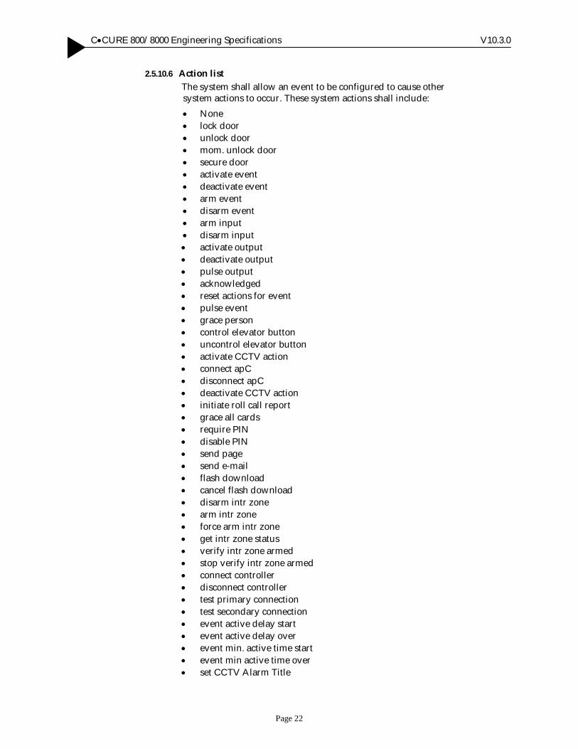
2.5.10.6 Action list The system shall allow an event to be configured to cause other system actions to occur. These system actions shall include: • None • lock door • unlock door • mom. unlock door • secure door • activate event • deactivate event • arm event • disarm event • arm input • disarm input • activate output • deactivate output • pulse output • acknowledged • reset actions for event • pulse event • grace person • control elevator button • uncontrol elevator button • activate CCTV action • connect apC • disconnect apC • deactivate CCTV action • initiate roll call report • grace all cards • require PIN • disable PIN • send page • send e-mail • flash download • cancel flash download • disarm intr zone • arm intr zone • force arm intr zone • get intr zone status • verify intr zone armed • stop verify intr zone armed • connect controller • disconnect controller • test primary connection • test secondary connection • event active delay start • event active delay over • event min. active time start • event min active time over • set CCTV Alarm Title
• start tour • cancel tour • suspend tour • resume tour • CCURE Watch flash download • CCURE Watch DSP filter download • CCURE Watch activate selected flash • CCURE Watch request file upload • CCURE Watch request file upload timed • CCURE Watch cancel flash loading • activate NetVue action • arm NetVue alarm • disarm NetVue alarm • latch event • unlatch event • toggle event • enable keypad commands • activate BiD action • toggle intr zone mode • disable keypad commands • show intr zone status • show intr zone offnormal points • clear violated intr zone • arm local intr zone • disarm local intr zone • toggle local intr zone • force arm local intr zone • show local intr zone status • show local intr zone offnormal points • clear local violated intr zone • shunt input • activate event until overide • deactivate event until overide • set reader security level 1 • set reader security level 2 • set reader security level 3 • set reader security level 4 • enable counting only • enable counting for events • enable counting (access restrictions) • set count • set personnel group count • set escorted visitors count • set escort count • set supervisee count • set supervisor count • lockout grace person • enhanced reader flash • enhanced reader cancel flash • set reader security level 0
• no area occupancy configured • de-muster area • Grace Carpool Group • disable door forced alarm • enable door forced alarm • disable door held alarm • enable door held alarm • disable door RTE • enable door RTE • disable door lock tamper • enable door lock tamper • disable door lock unsecured • enable door lock unsecured • disable door open alarm • enable door open alarm • disable door DSM tamper • enable door DSM tamper • lock local door • unlock local door • secure local door • de-muster A ll • iSTAR database backup • grace carpool group • 1st phase acknowledged • toggle event • set system wide threat level to • set clearance filter 1 • set clearance filter 2 • set clearance filter 3 • set clearance filter 4 • set clearance filter 5 • set clearance filter 6 • update certificate • update host certificate • update all certificate • accept sign certificate • deny sign certificate • cancel all reader flash downloads • enable advanced monitor input actions • disable advanced monitor input actions • allow conditional access cycle • zero occupancy • Set Dynamic Area Manager Count • Set Managed Personnel Count • Set Conditional Access Personnel Count
2.5.10.7 Action reset The system shall control, on an action by action basis, whether an operator, responding to an event, may reset an action without
acknowledging the event. A ll actions resulting from an event activation shall automatically reset upon the event being cleared.
2.5.10.8 Time control It shall be possible to control via a user defined time schedule the period during which an event shall be armed and therefore capable of being activated by other system actions.
2.5.10.9 Graphic map display The system shall allow a graphic map display to be linked to an event. This graphic map shall be available to the system operator to display when responding to the event activation. Graphical maps shall be centralized in the network on a shared disk and be available for display on all operator workstations.
2.5.10.10 Automatic graphic map display The system shall allow for the automatic display of a graphic map linked to an event. This graphic map shall be available to the system operator to display when responding to the event activation. At the Monitoring Station, when an event is configured to automatically display a map, a map will pop up each time the event is activated. The map will disappear when the event is acknowledged. Graphical maps shall be centralized in the network on a shared disk and be available for display on all operator workstations.
2.5.10.11 Event activation for unacknowledged events The system shall allow the user to specify in an “ Unacknowledged” event to activate if an associated event remains unacknowledged for a specified period of time. When an event acknowledgement becomes overdue, its state is changed to “ acknowledgement overdue” , and the change is then sent to the journal. The associated “ Unacknowledged Event” is then activated.
2.5.11 Door Definitions
2.5.11.1 Door names Each door shall be addressed within the system by a unique fifty (50) character user defined name. The use of code numbers or mnemonics shall not be accepted.
2.5.11.2 Door description The system shall provide the ability to add door description text to each door definition. There shall be no limit to the amount of text that can be used to describe the door.
2.5.11.3 Construction Each door shall be comprised of one (1) or two (2) card readers, a door position status alarm point, a request to exit alarm device, PIN pad control, and door lock control output point designator. The use of a second card reader and a request to exit device should be
mutually exclusive in the system, such that a door cannot be configured with both objects.
2.5.11.4 Access modes The system shall allow readers to be configured to operate in either of the following modes: (a) Card Only (b) Card + Personal Identification Number entry (c) Card + Personal Identification Number as specified by time specification (d) Free Access (e) Personal Identification Number is always required
It shall be possible to control the access mode assigned to the door by either manual (operator) command, upon event activation or based upon time specification. Each change of access mode shall be logged to the historical activity log and shall be available for report/ replay.
2.5.11.5 Reader states The system shall support a number of different reader states: (a) Controlled - in this state, the reader shall operate based upon the mode
assigned to the door where the reader is located. If the door is in an access control mode, the reader shall read access cards and pass the information to the field panel
(b) Disabled - in this state, the reader shall not read cards and shall not pass card information to the field panel. It shall be possible to configure the reader to be disabled, but allow the door to continue to operate, allowing the request to exit device to shunt the door sense monitor point. Operator and events can continue to issue commands to unlock the door.
It shall be possible to control the reader state by either manual (operator) command, upon event activation or based upon time specification. Each change of reader state shall be logged to the historical activity log and shall be available for report/ replay.
2.5.11.6 Reader operation The system shall allow a reader to be configured to operate using the following functions: (a) Readers shall read cards while the door is in the open position (b) Door lock shall automatically lock upon the door being opened (c) Automatic locking of the door lock after the door opened shall be
delayed for a user defined time period (d) Separate timers for the operation of the door lock and the software
shunting of the door position status alarm point. The shunting of the door contact following the presentation of a valid access card or activation of the request to exit device shall be accomplished by software control. The use of a hardware shunt shall not be accepted
(e) A separate (alternate) shunt timer shall be available to extend the door shunt time after an access granted access occurs when the card swiped has the ADA flag checked in the card record. Additionally, a second alternate shunt relay shall also be configurable that will be activated
when access is granted to a card with the A lternate Shunt/ ADA checkbox selected.
(f) The user shall be able to specify an shunt expiration output to be triggered a configurable number of hh:mm:ss before the alternate shunt expires
(g) PIN entry on the reader keypad shall be required during a specified time specification after a card access (unless a manual action or event has disabled PIN)
2.5.11.7 Reader LED and Annunciation (beep) Patterns The system shall provide the operator the ability to assign standard Reader LED settings to the card readers as well as the ability to assign positive and negative tones with alternate patterns Beep/ LED patterns. This feature shall be configurable through the system variables screen.
2.5.11.8 Door alarms The system shall allow each door to be configured to cause a variety of events to occur based upon activity at that door. The events may be caused by each of the following activities: • Door held open • Door forced open • Reader duress • Reader communication failure • Admit access • Reject access attempt • Visitor card admit access • Visitor card reject access • Noticed card admit access • Noticed card reject access • Passback violation • PIN required • Tamper • Admit causes CCTV action • Reject causes CCTV action
2.5.11.9 Output Activation The system shall allow each reader to be configured to cause an output to activate based on activity at that door. The following events may cause an output to activate:
• Output activation during reader communication failure • Output activation while tampered • A lternate shunt relay • Shunt expiration relay
2.5.11.10 Duress alarm The system shall allow a person at a card reader controlled door to signal the system operator that they are entering the area under duress. This duress alarm should not be evident at the card reader. The access controls normally executed by the system, person is authorized for that door, at that time and that day of the week, shall still be enforced for a duress access event.
2.5.11.11 Linkage viewing The system shall provide the operator with the ability to view from the door data screen a listing of all groups that contain the particular door, and a listing of all events that control the door.
2.5.11.12 PIN required during time specification The system shall allow for a time specification to be configured and associated to a door that will require a valid PIN entry for access during the specified time spec after a card access (unless a manual action or event has disabled PIN).
2.5.11.13 Reader LCD messages The system shall allow user to customize a set of LCD reader messages. A ll messages, as well as date and time formats shall be downloaded to the controller and will be used on all readers configured on that panel. [For this release, only characters contained in the English code page will be supported for display on the RM reader.].
2.5.12 Enhanced Door Monitoring (iSTAR) The system shall have the support for additional input monitoring conditions at a door, as well as activity reports related to the state of these inputs. The system shall support an addition of up to 16 total inputs per door, 14 of them are in addition to the normal RTE and DSM. These 14 may consist of any mix of lock sensor, lock release, DSM, or RTE inputs.
2.5.12.1 Definitions
2.5.12.1.1 Lock Sensor Input - The system shall allow the user to configure multiple lock sensor inputs at the door. The system shall monitor the lock sensor inputs and report lock unsecured or lock tamper when the input is in the incorrect state based on the current state of the door and other associated inputs.
2.5.12.1.2 Lock Release Input - The system shall allow the user to configure multiple lock release devices at the door. The system shall monitor the lock release devices, optionally annunciate changes in their state, and use their state as part of the basis for deciding the lock unsecured, lock tamper, and door open alarms.
2.5.12.1.3 M ultiple DSM /RTE Input - The system shall allow the user to configure multiple door switch monitor inputs (DSM) and Request to Exit (RTE) inputs at the door.
2.5.12.1.4 Door Forced Alarm Suppression – The system shall support the ability for the user to configure a time based or manual suppression of door forced open alarms on a per door basis.
2.5.12.1.5 Door Held Alarm Suppression - The system shall support the ability for the user to configure a time based or manual suppression of door held open alarms on a per door basis.
2.5.12.1.6 Time and M anual Control of RTE - The system shall support the ability for the user to configure a time based or manual control of the operation of the RTE function on a door.
2.5.12.1.7 Door Latch Relay Change - The system shall support the ability for the user to configure the door latch/ strike relay (DLR) to be activated for the full door unlock time regardless of DSM state. The door would remain shunted for this period.
2.5.12.1.8 Door Shunt Operation Change - The system shall support the ability for the user to configure the door to remain shunted for the full shunt time regardless of the state of the DSM.
2.5.12.1.9 Door debounce Per Door Basis/Alarm Grace - The user shall be able to program a time interval for alarm grace after the unlock time interval expires or the door closing to eliminate false alarms caused by bouncing doors.
2.5.12.2 Configuration The general door screen shall allow the user to bring up a separate screen named “ door monitoring” to configure the lock release devices and other door monitoring settings for that door.
2.5.12.2.1 Available Inputs – Shall display general-purpose inputs on the controller that are available for use in door monitoring. Available inputs are all general purpose inputs on the same controller as the door, that do not already have a special purpose such as being used by other doors or by intrusion zones. An exception is made for lock release inputs, which may be shared by multiple doors.
2.5.12.2.2 Selected Inputs – Shall display all inputs monitored by the door. Shows the name and input type.
2.5.12.2.3 Edit Inputs – Button widget that allows users to edit inputs.
2.5.12.2.4 Add – Shall add the selected input in the Available Inputs list to the selected list as the selected input type. Removes it from the available list. Enabled while an input is highlighted in the available list.
2.5.12.2.5 Input type column in Selected Inputs browser – Indicates the purpose for which the door shall use the input. For most inputs, when an input is first added to the list, the type will be None and the correct type must be selected – the screen cannot be exited if any input has type “ none” . An input that has been previously selected as a lock release input for another door shall have type ‘lock release’ when added to a new door. These types of the ‘lock release’ inputs cannot be changed unless the current door is the only door using that lock release input.
2.5.12.2.6 Remove – Removes the highlighted input in the Selected Inputs list from the controlled list. Enabled while an input is highlighted in the Selected Inputs list.
2.5.12.2.7 Remove All – Removes all of the inputs in the Selected Inputs list from the controlled list. Enabled while the controlled list is not empty.
2.5.12.2.8 Unlock grace time 1/10 seconds – This allows the configuration of the unlock grace time for the door. Units are 1/ 10 seconds.
2.5.12.2.9 Door open grace time 1/10 seconds – This allows the configuration of the door open grace time for the door. Units are 1/ 10 seconds.
2.5.12.2.10 Door close debounce time 1/10 seconds – This allows the configuration of the door close debounce time for the door. Units are 1/ 10 seconds.
2.5.12.2.11 Change time 1/10 seconds – (Lock release, Bond sensor, Latch bolt, Cam sensor, DSM side A, DSM side B, or RTE). These fields allow configuration of the value of the time during which this type of input is expected to change after other conditions have changed. Units are 1/ 10 seconds.
2.5.12.3 Events Four access events associated with enhanced door monitoring shall be available to the user when the ‘Access Events…’ button is selected.
2.5.12.3.1 Door Open Alarm causes event - The user shall be able to configure a unique event that shall be activated when the door open alarm is active for this door. Double-clicking brings up the Event Select Window.
2.5.12.3.2 Lock Unsecured causes event - The user shall be able to configure a unique event that shall be activated when the lock unsecured alarm is active for this door. Double-clicking brings up the Event Select Window.
2.5.12.3.3 Lock Tamper causes event - The user shall be able to configure a unique event that shall be activated when the Lock Tamper alarm is active for this door. Double-clicking brings up the Event Select Window.
2.5.12.3.4 DSM Tamper causes event - The user shall be able to configure a unique event that shall be activated when the DSM Tamper alarm is active for this door. Double-clicking brings up the Event Select Window.
2.5.12.3.5 Event Activation After Consecutive Rejects - The system shall allow the user to configure the number of consecutive rejects, and the time that can lapse between the consecutive rejects. Consecutive rejects can be cards, keypad commands, or pin number rejects. If the number of consecutive rejects occurs before the timer expires, a system activity message is displayed on the Monitoring Station.
2.5.12.4 M onitoring
2.5.12.4.1 Door Status Door Open A larm status, Lock Tamper status, Lock Unsecured status, and DSM Tamper status shall all report back status on the monitoring station. The enhanced door status shall report on the following causes list type states, RTE enable/ disable, door forced alarm enable/ disable, door held open alarm enable/ disable, door open alarm enable/ disable, lock tamper alarm enable/ disable, lock unsecured alarm enable/ disable, DSM tamper alarm enable/ disable. The user shall be able to fire a manual action on any of the above listed. These states may also be affected by event actions.
2.5.12.4.2 Door Details - Cause A tab shall be available to the user for detailed door status for all enhanced doors to show the causes for the modifiable door functions and associated manual action buttons. This screen shall change to show the cause of the selected function when the appropriate radio button is selected. The available manual actions shall change appropriately.
2.5.12.4.3 Door Details - Status A tab shall be available to the user for detailed door status for all enhanced doors to show the status of alarm conditions supported by the door. This shall show the inputs monitored by the door, their state, and any door alarm condition derived from that.
2.5.12.5 Journal
2.5.12.5.1 Lock Tamper Alarm – Shall report input name indicating which input caused the lock tamper alarm condition.
2.5.12.5.2 Lock Unsecured Alarm – Shall report input name indicating which input caused the lock unsecured alarm condition.
2.5.12.5.3 Door Open Alarm – Shall report input name indicating which input caused the door open alarm condition.
2.5.12.5.4 DSM Tamper Alarm – Shall report input name indicating which input caused the DSM tamper alarm condition.
2.5.13 Alarm Configuration
2.5.13.1 Alarm point name Each alarm point shall be addressed within the system by a unique fifty (50) character user defined name. The use of code numbers or mnemonics shall not be accepted.
2.5.13.2 Alarm description The system shall provide the ability to add a description text to each alarm point definition. There shall be no limit to the amount of text that can be used to describe the alarm point.
2.5.13.3 Alarm point configuration The system shall accept as an alarm input: supervised alarm inputs, unsupervised alarm inputs and dedicated alarm points such as device tamper alarms and controller AC power failure.
2.5.13.4 Alarm arming Within the system there shall be two (2) separate and distinct states for alarm points. The system shall allow alarm points to be placed OFF/ ON LINE. While a point is off line, the system shall not monitor the alarm point or alarm circuit for change of state. When a supervised alarm point is placed on line, the system shall begin to monitor and annunciate supervision alarms for the alarm circuit. The second state for alarm points shall be the ARMED/ DISARMED state. When an alarm point is armed, the system shall begin to monitor the alarm device for change of state (normal to alarm and alarm to normal). The alarm device change of state shall be acted upon by the system, based upon the user-defined configuration of the system. A larm points shall be automatically armed/ disarmed during user programmable time
periods and may be manually armed/ disarmed from any workstation by an authorized system operator.
2.5.13.5 Additional alerts The system shall also generate alerts for the following: • Enclosure tampering • controller communication loss • Reader tampering • Reader communication loss • A larm tampering (supervised) • AC power loss • Low battery • Onboard battery low (iSTAR Edge only) • FAI State (iSTAR Edge only, models 0312-5010-02 and
0312- 5010-04) • FAI Relay Control (iSTAR Edge only, models 0312-5010-02 and
0312- 5010-04) • FAI Key State (iSTAR Edge only, models 0312-5010-02 and
0312- 5010-04)
2.5.13.6 Alarm supervision When using supervised alarm points, the system shall monitor for Open Circuit, Short Circuit, in addition to Normal/ Abnormal conditions.
2.5.13.7 Linkage viewing The system shall provide the operator with the ability to view, from the alarm input data screen a listing of all groups which contain the particular alarm input and a listing of all events which control the alarm input.
2.5.14 Output Control Relay
2.5.14.1 Output control relay name Each output control relay shall be addressed within the system by a unique fifty (50) character user defined name. The use of code numbers or mnemonics shall not be accepted.
2.5.14.2 Output control relay description The system shall provide the ability to add a description text to each output control relay definition. There shall be no limit to the amount of text that can be used to describe the point.
2.5.14.3 Activation control Output control relays shall be defined as maintained or momentary. Maintained output control relays shall be configured to be activated/ deactivated based upon a user defined time schedule, linked to a system event or operator command. Momentary output control relays shall have a user-defined pulse time (defined in 0.1 second increments). It shall be possible to use the momentary output control relays for the momentary control of devices other than door locking hardware.
2.5.14.4 Link programs The system shall not place limitations upon the number of links that can be defined in the system. The ability to link inputs and outputs that shall be global such that the change of state of an alarm input on one controller could cause the activation of an output on a different controller.
2.5.14.5 Linkage viewing The system shall provide the operator with the ability to view from the output control relay data screen a listing of all groups that contain the particular output control relay and a listing of all events that control the point.
2.5.15 Operators
2.5.15.1 Password The system software shall be capable of identifying up to forty thousand (40,000) system operators. Passwords shall be up to twenty (20) characters.
2.5.15.2 Operator name Each operator authorized to operate any portion of the system shall be addressed within the system by a unique fifty (50) character user defined name. The use of code numbers or mnemonics shall not be accepted. The operator name will be used throughout the system to identify commands and functions that the operator has executed.
2.5.15.3 Operator activity All commands issued by a system operator while monitoring system activity including locking/ unlocking doors, event acknowledgment, etc. shall be stored in the historical archive for later recall. The archived command shall include the operator name, time and date the command was issued and the command issued by the operator.
2.5.16 Operator Privileges
2.5.16.1 Privilege control Each operator shall be assigned an operator privilege level. Operator privilege levels define the individual commands within the system which the operator is authorized to execute.
Only those commands which an operator is authorized to execute will be available to that operator. If the operator is not authorized to execute a command, that command will be disabled in the displayed toolbar.
2.5.16.2 Privilege level The system shall provide the ability to group similar privilege controls into a defined privilege level, which can be assigned to system operators.
Privilege levels shall be defined and assigned to provide different levels of controls within the system:
(a) Configuration privilege - shall control what commands, generally related to system data, and operator may execute.
(b) Event monitoring - shall control which objects within the system the operator can monitor and run reports against.
2.5.16.3 Privilege level construction There shall be no limit to the number of privilege levels that can be defined in the system.
Each privilege level shall be addressed within the system by a unique fifty (50) character user defined name. The use of code numbers or mnemonics shall not be accepted.
The system shall provide the ability to add a description text to each output control relay definition. There shall be no limit to the amount of text that can be used to describe the point.
The system shall provide the system administrator the ability to disable a defined privilege level. Any operator who has been assigned this privilege level will be prevented from issuing any commands within the system.
2.5.16.4 Administrative privilege level construction When constructing the administrative privilege levels within the system, the operator shall assign each administrative command in the system to an assigned access right. These access rights classifications shall be: (a) No Access - the operator cannot execute these commands (b) Read-Only - the operator can open the screen for viewing of defined
data. The operator is prevented from making any modification or deletions to the defined data.
(c) Create/ Edit/ Delete - The operator can create new objects, edit and delete existing object. The operator however, can not edit the default object definition.
(d) Full Access - The operator can create new objects, edit and delete existing object. The operator can also edit the default object definition.
When building the privilege level, the system will provide the administrator with a listing of all the commands in the system. By default, all system commands will be assigned to the No Access access right classification. The administrator can then move the command to the appropriate access rights classifications.
2.5.16.5 M onitoring privilege control construction The monitor privilege shall control which message types and specific objects an operator can view/ control while in the event monitoring program. The monitoring privilege shall further control which message types and specific objects an operator may view while running historical journal reports.
The monitoring privilege shall also allow the System Administrator to administer access to manual actions and certain menu options of
the Monitoring Station. These monitoring privileges shall restrict which security objects a user can control, and which manual actions the user can perform on those objects.
When constructing the monitoring privilege, the administrator shall select the message types the operator can view. These message types shall include:
(a) Operator log in/ log out (b) Card admitted (c) Card rejected (d) Operator log message (e) Object state change (f) Manual operator actions (g) System activity messages (h) System error messages (i) Device activity messages (j) Device error messages (k) Asset general activity (l) Asset authorized movement (m) Asset unauthorized movement (n) Asset attempted movement (o) Asset location update (p) Guard Tour action (q) Guard Tour activity (r) Guard Tour error (s) Tour Stop activity (t) NetVue activity (u) Keypad command activity (v) Intrusion zone activity (w) Intrusion zone error (x) Area activity (y) Double Swipe (z) Maintenance Mode
The system administrator shall then define the specific objects, i.e. doors, alarm inputs, outputs, field panels, etc. within the system an operator can monitor.
If the operator is not authorized to monitor an object, by extension, the operator shall be restricted from issuing manual commands against the object.
2.5.16.6 M anual Action Challenge The system shall provide a Manual Action Challenge selection box in the monitoring privilege set up window. If enabled, once a user attempts a Manual Action at the guard station, the login username and password dialog box will be displayed. The user must then enter a username and password of a privileged user in order to complete the Manual Action. Otherwise, the user is given an error message and not allowed to activate the requested manual action. If a valid username and password is provided, following the completion of the Manual Action, login privileges shall revert back to the originally logged in user.
2.5.16.7 Privilege level assignment listing The system shall provide a report listing of all operators who have been assigned a particular privilege level.
2.5.17 Personnel Views
2.5.17.1 Personnel View Selection The system shall provide for default Personnel Views to be assignable to authorized Users of the system. These Views shall include $Default System Person View, $Global Clearances, RTOD Person View, $Multiple Cards, $Multiple Cards & Pin, $Government Card, and $Government Card & Pin.
2.5.18 Card Record Definitions
2.5.18.1 Card data The system software shall allow for card numbers up to twenty (20) digits (64bits) on iSTAR controllers.. The apC/ L/ 8X will only support (10) digits (32bit) card numbers.
2.5.18.2 Extended Card Support – Card Holder Unique ID (CHUID) The system shall support card numbers larger than 32 bits. The system shall have the ability to create these larger card numbers using personnel fields.
The system shall increase the card number field to support a maximum of 64bits for non-government card Users that require a longer card number. The new card number will be represented by a CHUID. For those Users requiring card number lengths greater than 10, the new card number length would need to be configured via the new CHUID Format Configuration.
Using the CHUID, the User would have the ability to set the card number length to 20 digits, which equates to the 64-bit non-government card number.
The system shall allow the User the ability to combine the following fields to create a single CHUID. These fields will be called Card#, CardInt1, CardInt2, CardInt3, CardInt4, Access Facility Code, Credential Series, Credential Issue, System Code, Agency Code, Issue Code and HMAC. Building a card number using these fields is referred to as Extended Card Support.
Note: Extended Card Support is not supported on apC/ 8X or apC/ L. Only iSTAR supports this feature. iSTAR Firmware v4.0 is required.
2.5.18.3 M ultiple Cards The system shall support multiple cards per person. The system will support up to 5 cards per cardholder, one of those credentials have the possibility to be a random PIN-Only credential. Both iSTAR’s with firmware v4.0 and apC/ L/ 8X’s will support 5 cards per-person. However, apC/ L/ 8X’s will not support the PIN-Only
credential because that feature utilizes the extended card support feature.
2.5.18.4 Copy Card
The user shall be able to copy information from one personnel record to another. A fter filling in the necessary fields, the user can click the OK button to save or the Cancel button to discard. If the user selects the Next button, the current record is saved and the next record is created for editing. This method utilizes the same behaviors as a regular addition into the cardholder database. Automated card number increment shall also be supported by the Copy action. Unique fields such as Card Number, Pin and Issue Code shall not be copied over. Neither shall the fields in the USERS table because users.user_name is utilized as a unique index in the database table.
2.5.18.5 User defined labels The system shall allow a privileged system operator to specify field name, field type, field restrictions and whether or not a field is mandatory and/ or enumerated. The system shall provide the operator the ability to view the card record layout, including the new labels, before the changes are put into use. The system shall provide the system operator the ability to make fields within the cardholder record not visible.
2.5.18.6 Card record layout The system shall allow a privileged system operator to define the placement of the user-defined fields within the personnel data screen.
2.5.18.7 Personnel records Personnel records shall be constructed to contain multiple pages of personnel data in system and user defined fields.
The system shall support a feature where the system administrator can assign background colors to personnel records in order to highlight records of interest. This feature shall accommodate the assignment of user-defined colors based on a single or multiple personnel record fields, and values, of interest. The background color assigned to a personnel field/ s shall be displayed when one or more values are applicable to the personnel record. The system shall support all personnel fields for assignment to background colors including user-defined fields, and multiple background color definitions can be configured. Should more than one background color be defined in the system, and a personnel record match multiple configurations, a user-defined associated priority shall be used to determine which background color to use when displaying the record.
The personnel data shall consist of a minimum of the following: (a) Card holder name (b) Encoded card number (c) Record ID number (system defined, operator view only) (d) Issue level
(e) Forty (40) clearance codes (f) Eight (8) custom clearances (g) Eight (8) custom events (h) Personal Identification Number (PIN) code (i) Facility number (j) Activation date and time (k) Expiration date and time (l) Unlimited number of user defined fields
• How many text fields (minimum forty (40) characters per field) • How many integer fields (numbers less than 32,767) • How many date fields (MM/ DD/ YY) • How many logical fields (selected/ not selected)
(m) Person type • Employee • None • Escort • Escorted Visitor • Visitor • Contractor
(n) Status flags • Card Expired • Card Disabled • Card Lost • Card Temporary •
(o) Access Control Options • Activate A lternate Shunt (ADA) Relays • Activate Anti-passback Event • Anti-passback Exempt • Notice Accesses • Asset Admin • Can Perform Guard Tour • Intrusion Zone Admin • Keypad Command Admin
(p) First and last name of operator that performed last edit of the card
holder information. This shall be defined by the system and shall be view only to the operator.
(q) Date and time last edit was performed on the card holder information. This shall be defined by the system and shall be view only to the operator.
(r) Stored image of the person (s) Stored signature of the person (t) Identification badge layout assigned to the person (u) Date last image was captured/ saved (v) Date last identification badge was printed (w) Supervision Status
2.5.18.8 Personal Identification Number (PIN) control The system software shall support up to a (9) digit PIN. The system software shall provide controls such that the Personal Identification Number (PIN) field in the personnel record can not be viewed by system operators. This restriction shall be enforced when viewing the record, running reports containing the PIN field, and exporting cardholder data.
When the hidden PIN control is set, the PIN field in the card record shall be displayed as a series of asterisks or bullets.
The system shall prevent running a query to find a card record that matches a particular PIN code.
2.5.18.9 Save Personal Identification Number (PIN) un-encrypted (optional feature) The system software shall allow storage of an un-encrypted PIN in a field in the personnel table so that the PIN can be read and changed in an un-encrypted form. Once you select the Save PIN un-encrypted check box in the System Variables Personnel Tab and click OK, the system processes each personnel record, decrypting the PIN and saving it in the personnel table. During this process, if the system is not able to write a decrypted PIN for any personnel due to a record being locked, it continues processing other personnel and will display the error report for unprocessed personnel.
2.5.18.10 (Pin-Only) Access Credential – Extended Card When multiple card support is enabled, the system shall allow 1 of the 5 access credentials assigned, to be defined as a PIN only access credential. The readers on the system shall know that the credential is a PIN only card. This feature shall rely on the extended card support. Extended cards are not supported on the apC/ L/ . iSTAR’s support this feature using iSTAR firmware v4.0.
2.5.18.11 Random PIN Generator – Extended Card The system shall provide a Random PIN Generator. The Random PIN Generator shall enforce uniqueness of PIN numbers throughout the entire system. Uniqueness of PIN’s will be enforced once the System Variable for “ Enable PIN-only Access credential” is enabled which will apply to automatically generated PIN numbers.
The Random PIN Generator shall respect the length of the PIN defined in the CCURE.ini file. PIN numbers entered with values less than the minimum PIN length will be padded with zeros to make the PIN length equal to the minimum value. Users will be required to enter the leading zeros at readers in order to gain access at PIN Only doors.
The system variable for “ A llow Pin Display” will control the masking of PIN and PIN Credentials. If the option is not checked, once the Generate Pin button is clicked a confirmation dialog box will display the visible PIN number and once this is closed the PIN will be masked.
2.5.18.12 Clearance Codes While the operator is editing a cardholder record, the system software shall provide a browser list of all defined clearance codes. The operator shall be able to assign up to forty of the clearance codes to the cardholder by moving the clearance code name from the defined list to the assigned list.
Controls shall be provided to assign a clearance code to the cardholder, remove an individual clearance code, and remove all assigned clearance codes from the cardholder.
The operator, if authorized, shall also be able to define/ edit a clearance from the card holder record screen.
2.5.18.13 Custom Clearance Codes The system software shall allow the user to add a custom clearance to a card holder while the operator is editing a card holder record. Up to eight (8) unique clearances including door or door group, time specification and expiration date & time and/ or activation date & time shall be configurable by the user in the card holder record.
2.5.18.14 Custom Events The system shall allow the user to monitor the access activities of a particular person. Within the cardholder record the user shall be able to add custom events that tie the door/ elevator and admit/ reject event (group) to a particular person. These events shall fire only when accesses are made by this particular person, through the particular doors/ elevators.
There shall be a maximum of eight (8) Cardholder Events per person.
2.5.18.15 M andatory data fields The system software shall provide a means whereby the system administrator may define certain user-defined fields in the personnel record as being mandatory. Personnel performing data entry on the card holder record shall be required by the system to enter information in all field marked by the system administrator as mandatory.
2.5.18.16 Choice List fields The system software shall provide a means whereby the system administrator may define certain user-defined fields in the personnel record as choice list fields. The system administrator shall be able to define the choice list and the values to be included in the choice list. The operator, when performing data entry, shall be able to choose one of the values defined in the choice list.
2.5.18.17 Card record import/export The system software shall provide means for bulk loading and bulk editing of card records through the use of a data file generated from another source. The external file shall be an ASCII file in comma delimited format.
The system shall also provide the ability to generate the same format file of existing card records, allowing the information in the system to be exported to other computers and applications. The system shall allow the user to select the card records that shall be included in the export file.
2.5.18.18 Query capabilities The system shall provide a card holder selection list, allowing the system operator to choose individual cardholder records from the selection list. The selection list shall provide a quick sorting display of all card holder records. The operator shall be able to set the sorting of the personnel list by: (a) card holder name (b) card number (c) first user defined text field (d) first user defined integer field
The system shall allow queries to be performed on any field or combination of fields within the card holder record. The system shall allow the queries to be performed based upon partial entry of data in a field, i.e. entering FI in the cardholder name field shall return all records where the name begins with the letters FI. The system shall allow a query based on a clearance or group of clearances.
2.5.18.19 Additional Card Query capabilities The system shall allow the ability to query by number of multiple cards assigned per person. The system shall allow the ability to query on card# e.g. starting card# through ending card #.
2.5.18.20 Badge Batch Print All The system shall allow the User to query on any criteria available in the system. Users shall have the ability to perform a Badge Print A ll against all the cards that appear from queried result list when CCUREID Batch Printing is enabled for the CCUREID Setup utility.
2.5.18.21 Alternate Shunt / Assisted access support (ADA) The system shall provide the ability to control a door for cardholders requiring assistance or an alternate shunt time. The system shall provide the ability to tag a card indicating the person requires and alternate shunt time. When the person presents their card at a door, and the person is authorized for that door, the system shall unlock the door as normal and shall activate a second output control relay, which may be used to control a door opening device. The shunt time for the door shall be extended beyond the normal shunt time (shunt period defined by system administrator in hh:mm:ss) allowing the person requiring the alternate shunt to pass through the door without generating an alarm.
The system shall provide the ability in the personnel screen to allow configuration of personnel as exempt from anti-passback testing.
This flag shall work with the AP Event flag on that screen so that if the AP Event flag is set but the person is exempt from testing, they shall gain access but shall still trigger anti-passback events if they violated anti-passback.
2.5.18.23 Previous activity report While viewing a cardholder record, the system shall provide the ability to review the previous activity of the cardholder. This shall be accomplished by pressing the “ Previous Activity” button on the card holder record screen. They system shall automatically perform a historical search for all previous access activity for the cardholder. This information shall be displayed to the system operator, with the ability to generate a report, either to a file or printer, while viewing the information.
2.5.18.24 Previous Activity Tab There shall be a tab, ‘Prev. Doors’, in the Personnel Record screen in the Admin application. A fter the user clicks the “ Limited prev. doors” button, the screen displayed in this tab will contain the last X* door activities of the edited card number. (This number is user defined in the system diagnostics).
The user shall have the option to display all previous door activity by selecting the “ Complete prev. doors” button. After the replay is finished, the user can either save the result by selecting the “ Save” button, or print the result with the “ Print” button. During the replay, the user can cancel it w ith the “ Stop” button.
2.5.18.25 Enabling a cardholder The system shall provide the ability to designate a person as a “ User” from the Edit Personnel Record screen’s User tab. A ll other user information features shall be disabled until the Person is designated as a valid user. Once the person is designated as a user in the Personnel Record, the user will be required to supply a username and set the user password before exiting the screen.
2.5.18.26 User configuration screen tab While the operator is editing a cardholder record, the system shall provide the ability to enable a user from the Edit Personnel Record screen’s User tab once the person has been enabled.
2.5.18.27 Enabling Breakthrough The system shall provide the ability to designate a user for event breakthrough.
2.5.18.28 iSTAR Global Antipassback iSTAR Global Antipassback allows multiple iSTAR Clusters to share Antipassback information.
iSTAR Global Antipassback is built on top of Cluster Antipassback. Members always ask their Master for the Antipassback decision.
Now, however, a concept of “ Ownership” is added. A card has only one “ Owner” . That Owner is a Master. Only that Master can make an Antipassback decision for that card. A ll other Masters and all Members are “ Non-Owners” of that card. They cannot make an Antipassback decision for that card. When an Antipassback request arrives at a Non-Owner, the Non-Owner will forward the request to the C• CURE 800 Host.
iSTAR Global Antipassback supports: current Antipassback location, time of last access, grace state, timed Antipassback, and Area Lockout.
2.5.19 Database Partitioning
2.5.19.1 Overview The system shall allow for the segmentation of data in the systems database such that different user groups can access only the data in their own partitions or in partitions designated as shared. The system shall also have the ability to assign any combination of partitions to a particular user, while assigning one as the “ home” partition. Partitioning in conjunction with administration privileges shall support two customer models: a multi-tenant facility or a campus facility.
2.5.19.2 Customer M odels Partitioning in conjunction with administration privileges shall support two customer models:
(a) Multi-tenant facility – A multi-tenant facility is defined as a single building controlled by a single C•CURE system. The building has more than one tenant with each tenant managing the access control for their own office space.
(b) Campus facility – A campus facility is defined as a single organization occupying one or more buildings which are controlled by a single C•CURE system. The space includes one or more user groups, and each user group managing their own access control.
2.5.19.3 Administrators The system administrator is the person responsible for all system maintenance as well as all common data. System administrators can use administration and monitoring privileges to further restrict user access to both partitioned and common data.
2.5.19.4 “Shared” partitions The system shall allow the system administrator ability to designate a partition as “ shared” . By sharing a partition, the system administrator grants all tenants/ user groups read-only access to all data within that partition, whether or not it is their own partition.
2.5.19.5 Types of partitioned data For each of the customer models previously described, the system shall allow for the partitioning of the following security objects:
(a) Personnel (b) Clearances (c) Time specifications (d) Doors (e) Door Groups (f) Elevators (g) Elevator groups (h) Nodes
For each of the customer models previously described, the remaining object types in the system shall be considered common data. Some examples of common data security objects include:
(a) Controllers (b) Floors (c) Floor groups (d) Inputs (e) Outputs (f) Readers (g) Areas (h) Time Zones (i) Personnel views
2.5.19.6 Rules for partitioned data (a) Non-partitioned systems – In C•CURE systems where no partitions are
defined, the system shall automatically assign all users and objects to the special $Standard Partition.
(b) $All groups – The system shall provide a special system-defined object group with names in the format of $Allxxx. For example, $All Inputs or $All Outputs.
(c) $Default records – The system shall allow for each partition to have a different $Default record for personnel and each object type that is partitioned. This shall allow users of each partition the ability to define their own default records.
(d) Object names – Object names shall be unique system-wide. If an object created in one partition is assigned the same name as an object in a different partition, and error message shall be displayed.
(e) Object linking – The system shall allow the partition administrator the ability to edit an existing object and link that object to other objects in the same partition. Clearances are the one exception as they may also be configured using objects from shared partitions. Additionally, clearances configured in the $Standard partition may include objects from any partition.
(f) Monitoring privileges – Users shall have the ability to view or control objects only in their own partition unless they are partition administrators.
(g) Activity printer – the system shall restrict messages displayed on the activity printer according to the partition on the node where the printer resides.
2.5.19.7 Global clearances partitioning feature The global clearances partitioning feature, when optionally enabled, shall extend the functionality of the standard partitioning in the following ways: (a) A system variable shall be used to allow clearances to be assigned
(b) Partition Administrators will have the exact same privileges as they do in normal partitioning mode (i.e. when the above option is not selected).
(c) A ll other users will have partitioning enforced the same as with normal partitioning with the following exceptions:
• A user may assign any clearance defined in their partition to any personnel record in any other partition.
• A user may remove any clearance defined in their partition from any personnel record in any other partition.
• A user may not remove a clearance defined in another partition from a personnel record in their partition.
• A user may not edit or view the definition of a clearance defined in another partition that is assigned to a personnel record in their partition.
(d) A special user editable personnel view, called “ $Global Clearances” will exist on all C•CURE 800 systems where at least one partition has been defined, and the “ A ll clearances to be assigned globally on partitioned system” variable is true. This view defines for all non-partitioned Administrators what personnel fields a user will have read access to when editing a personnel record from a partition other than their own.
(e) For a personnel browse or query, the result list will include personnel from all partitions that match the search criteria.
2.5.19.8 Enhanced Partitioning The system shall support the capability to allow the user to specify partition groups with multiple partitions for the sharing of doors, clearances, cardholders, etc. Users will be able to set a partition as “ shared by all” or “ shared with selected” . Users shall have the ability to specify a Partition Administrator individually for each partition or for multiple partitions.
2.5.19.9 Partition Configuration (a) Shared with selected partitions - If checked the “ Shared with all
partitions” checkbox gets disabled, lists of available and selected partitions gets enabled.
(b) Shared with all partitions - If checked the list of selected partitions shall be blank and disabled, a list of available partitions shall display all partitions and gets disabled. “ Shared with selected partitions” checkbox gets disabled.
(c) Available partitions - Shall display all currently configured database partitions.
(d) Selected partitions - Members of selected partitions shall have read access to objects configured in the partition being configured.
2.5.20 Automated Personnel Data Import
2.5.20.1 Overview The system shall provide a means to import personnel information from an external ODBC database other than import from a flat file. Additionally, the import shall execute in the background periodically to avoid the need to run the Administration application each time personnel data is to be imported. The import
procedure shall also perform the necessary validity checking to prevent corruption of the C•CURE system personnel table.
2.5.20.2 Automated import name Each Automated import shall be addressed within the system by a unique fifty (50) character user defined name. The use of code numbers or mnemonics shall not be accepted.
2.5.20.3 Automated import description The system shall provide the ability to add a description text to each automated import definition. There shall be no limit to the amount of text that can be used to describe the alarm point.
2.5.20.4 Query during time specification The system shall provide the ability to enter a time specification in order to restrict automated import activity for an automated personnel data import.
2.5.20.5 Interval The system shall provide the ability to designate a time interval in minutes and seconds before the next import query is run during the designated time specification. The system shall allow the option of keeping the automated import query option connected between import queries.
2.5.20.6 Import options The system shall allow the user to specify how the records are retrieved from the external database during the automated process and the amount of detail the import activity log will display after an automated import is run.
2.5.20.7 Data Source(s) The system shall allow the user to select from a list of external databases. It shall allow the user to enter a user ID and password if one is required by the external database.
2.5.20.8 LDAP Automated Cardholder Import The SMS shall support a means to import personnel information from an external Lightweight Directory Access Protocol (LDAP) - compliant data source.
The LDAP data source connection shall allow the user to select from the available listed object classes in the schema to filter data from the source. Filtering shall also be available via Distinguished Name (DN) reference and search string input by the user.
LDAP automated imports shall recurrently execute in the background at a user-specified interval, avoiding the need to run the SMS application each time a personnel data import is necessary. Method options for scanning the LDAP source for added, modified, and deleted records shall be available. The import procedure shall perform the necessary data validation to prevent corruption of the SMS personnel table.
The LDAP automated import functionality shall include status and error logging capabilities. A status log tab within the import definition screen shall allow the user to view activities related to the performance of the import procedure. The level of logging shall be user controlled, from no logging to logging of both activity and error related entries. These entries shall be optionally written to a log file and/ or Windows Event Log.
2.5.20.9 Role Configuration The SMS shall support a means to import clearance information from an external source (ODBC or LDAP) via the use of role-based clearances.
Roles shall be uniquely defined in the SMS as consisting of a mandatory title, optionally in combination with a location. The title shall correspond with a business assigned job title and the location shall correspond with a business site location.
The user shall be able to define an unlimited number of titles and locations, and define role objects that reference the title and location values in combination. Each title and location object definition screen shall display role objects to which they are already assigned. The role object shall be defined as having from one to forty defined clearances. Data imported into the SMS having a title and location value that matches a defined role in the SMS, shall have the corresponding clearances for that role assigned to the personnel record.
Clearances added or removed during role definition modifications shall be reflected automatically within personnel records upon saving the role definition. Personnel records that are locked at this time due to usage in the SMS interface shall be skipped. The role definition screen shall have a correction button available to allow users to update locked records that had been skipped during previous clearance and role updates.
Clearances populated into a cardholder record via the Automated Import and role based process shall be unavailable to users for removal. User removal of clearances populated into a cardholder record via manual methods, not pertaining to an assigned role, shall be permissible.
A personnel view shall be available to include read-only fields that reference a title, location, and role value. The Automated Import shall result in these personnel view fields being populated with the appropriate values for that personnel record.
2.5.21 Clearance Codes
2.5.21.1 Definition The clearance codes shall be the definition within the card holder record which controls when and where a person or vehicle is authorized to move within a protected area. The clearance code shall be a function of combinations of reader locations and time specifications.
2.5.21.2 Clearance names Each clearance code shall be addressed within the system by a unique fifty (50) character user defined name. The use of code numbers or mnemonics shall not be accepted.
2.5.21.3 Activation/Expiration
The user shall be able to select whether or not they would like a regular door or elevator clearance to have a custom activation and/ or expiration date and time assigned.
2.5.21.4 Construction The system shall provide the operator with pick lists of previously defined doors, door groups and time specifications. The system shall allow the operator to create a combination of a door or door group with a time specification. The system shall allow each clearance code to contain a minimum twenty four (24) door (group) and time specification combinations.
2.5.21.5 System usage The clearance codes shall be available to the system operator as a pop-up list, while the operator is editing a card holder record. The system shall allow a clearance code to be assigned to multiple card holder records.
2.5.22 Custom Clearances
2.5.22.1 Definition
Custom Clearances shall allow the user to customize access control clearance information for each person by adding sets of unique clearance information including door or door group, time specification and expiration date & time and/or activation date & time information to the personnel record for a person.
The date & time configuration for the activation and expiration fields on the clearance screen shall be similar to that for the personnel activation / expiration date fields, and shall support time zone handling in the same manner that those fields support it. The date & time shall be configured and presented in the user interface using the local time zone of the admin user, but shall be stored internally in GMT.
2.5.22.2 Construction The card holder record shall include a Custom Access tab including all custom access clearances configured for this person. Clicking on a row shall highlight and select the clearance to be operated on by the Modify or Delete buttons. The Type column shall display the access object type: door, door group, elevator or elevator group. The Name column shall display the name of the configured access object. The Floor or Floor group column shall be blank if type is door or door group, otherwise it shall display the name of the configured floor or floor group name. The Time Specification column shall display name of the time specification configured. The Activation and Expiration columns shall be blank if the field is not configured, otherwise they shall display the configured
activation and/ or expiration date and time values. The width of the columns shall be adjustable by the user.
2.5.22.3 System Variables The System Variables screen Personnel tab shall have a new field added that allows the user to configure how many custom clearances are allowable for each person. The maximum is 8 but the user may set the limit lower or to 0.
2.5.23 Reports
2.5.23.1 Lack of Use There shall be a selection, "Query by Inactivity" in the Admin application under the Personnel drop down menu. This shall allow a user to select a date and list all cardholders that have not had door activity since the indicated date. The date shall be user configurable by using the system diagnostics utility, with a default of 180 days.
2.5.23.2 Data storage All programmed and transactional history is automatically stored to the hard disk for later recall. Information written to the hard disk shall be immediately available for report generation.
2.5.23.3 System function The system software shall be able to generate reports without affecting the real-time operation of the system.
2.5.23.4 M edia Reports shall be generated from the hard disk and generated to the operator’s screen, hard disk, or printer(s).
2.5.23.5 Search criteria The database shall be structured such that the operator shall determine the search parameters based on variables available on the individual report menu. Systems requiring the user to type complicated search strings are not acceptable.
2.5.23.6 Report types Programmed data reports shall be available for the following information:
2.5.23.7 Database configuration reports The system shall be capable of producing reports of database configuration information. These database configuration reports shall include the following:
2.5.23.7.1 Hardware configuration (1) apC/ L/ 8X and iSTAR controllers (2) A larm inputs
2.5.23.7.2 System configuration (1) Events (2) Doors (3) Holidays (4) Time specifications (5) Time zones (6) Clearances (7) Real time event printers (8) Administrative privileges (9) Monitoring privileges (10) Area (11) Elevator (12) Floor (13) Map (14) Node
2.5.23.7.3 Group reports (1) Door groups (2) Event groups (3) Input groups (4) Output control points (5) Area group (6) Elevator group (7) Floor group (8) NetVue A larm group
2.5.23.7.4 Time zone report (1) Report of clearances with components in different time zones (time
zone mismatch report) (2) Time zone report
2.5.23.7.5 Types of replay (1) Report activity log (2) Report audit log (3) Report both activity and audit logs
2.5.23.7.6 Activity Reports
Activity reports shall be available for the following: (1) Select personnel for report (2) Select personnel group for report (3) Select message type for report (4) Select security items for report (5) Select assets for report
2.5.23.7.7 Incident ID Reports The system shall support an option to generate a unique identifier number upon the activation of all user defined system events. This ID number shall be displayed in the system monitoring station and in any related activity/ history report. This unique ID number can be used in an activity report in order to display only associated messages/ actions related to the specified event ID.
2.5.23.7.8 Audit Log Reports
Audit trail reports shall be available for the following based on all users or selected users: (1) Audit trail creations (2) Audit trail deletions (3) Audit trail modifications
2.5.23.8 Report Selection Depending upon the type of report being generated by the system operator, the system shall provide a listing of previously defined reports. The operator shall be able to pick an existing report, modify an existing report or generate a new report.
2.5.23.9 System defined reports The system shall contain pre-defined reports that shall report the database configuration for each of the following: (1) Area (2) Holidays (3) Time specifications (4) Time zones (5) Clearances (6) Elevator (7) Floor (8) Map (9) Node (10) Event (11) Door groups (12) Area groups (13) Elevator groups (14) Floor groups (15) Event groups (16) Input groups (17) Intrusion zones (18) Keypad commands (19) Guard tour (20) Control output relay group (21) Time specification detail which shall indicate all actions, clearances,
input point, output points, etc. Which are affected by the time specification
(22) Authorized card holder report, selected by specific door, which shall report all card holder who have access privilege through a defined door. The report shall indicate the door name, cardholder's name, card number, day(s) of the week and associated time of day, and clearance name.
2.5.23.10 Report Creation The system shall allow an operator to define reports and the contents contained within the report. There shall be no limit to the number of defined reports. Based upon the type of report being created, the system shall provide a pick list of items that may be included within the report.
The reports that the operator shall be able to create and the fields that may be contained within these reports shall include:
2.5.23.10.1 apC/ L/ 8X and iSTAR controllers (1) controller name (2) controller description (3) On-line (4) controller type (5) Address switch setting (6) Serial port (7) Poll period (8) Poll period while in communications failure (9) Poll time-out delay (10) Communications failure delay time (11) Time zone (12) Time spec (13) controller phone number (14) Connection type (15) Dial-up modems for unit (16) Download wait period
2.5.23.10.2 Output control point (1) Output name (2) Output description (3) On-line (4) controller unit (5) Related door/ elevator floor (6) Pulse duration (7) Board (8) Board type (9) Normally energized (10) Output type (11) Slot index
• Visitor admit • Visitor reject • Held open • Forced open • Duress
(4) Door switch monitor point (5) Door request to exit monitor point (6) Door latch relay (7) Door alternate shunt (ADA) relay (8) Shunt expiration relay (9) A lternate shunt time (10) Shunt expiration relay time (11) Reader 1 (12) Reader 2 (13) Unlock time (14) Shunt time (15) Pin entry required during time specification
2.5.23.10.7 Reader (1) Reader name (2) Reader description (3) On-line (4) Reader technology (5) controller to which reader is connected (6) Output control point linked to communication failure (7) Tamper triggers output (8) Tamper triggers event (9) Board (10) Board type (11) Card format 1 (12) Card format 2 (13) Card format 3 (14) Card format 4 (15) Card format 5 (16) Card format 6 (17) Card format 7 (18) Card format 8 (max for apC/ L/ 8X is now 8 per reader/ per
apC/ 8X panel) (19) Card format 9 (20) Card format 10 (max for iSTAR is 10 per reader/ 128 total
downloaded to an iSTAR. 128 total system-wide. (21) Pin required during time spec (22) Related door/ elevator (23) Slot index (24) Time spec enabling pin (25) Type
2.5.23.10.8 Communication port (1) Port name (2) Port description (3) On-line (4) Port type (5) Port time-out delay
2.5.23.10.9 Real time event printer (1) Workstation name (2) Printer description (3) Printer port identification (4) Page length (5) Page width (6) Privilege level (7) Abnormal status event (8) Initialization string (9) Header (left, center, right) (10) Footer (left, center, right)
2.5.23.10.10 CCTV matrix switcher (1) Clock synchronization (2) Communications fail delay (3) Description (4) On-line (5) Poll period (6) Port (7) Protocol (8) Switcher name (9) Wait time (10) Time zone
2.5.23.10.11 CCTV action (1) Action name (2) Action type (3) Description (4) Parameters (5) Switcher
2.5.23.10.12 Host modem (1) Connect to host wait time (2) Description (3) Direction (4) DTR off timer (5) Initialization string (6) Modem answer delay time (7) Modem name (8) Modem phone numbers (9) Modem response wait time (10) Modem status check time (11) On line (12) Port (13) Re-dial/ reconnect delay time (14) Use DTR
2.5.23.10.13 Administrative privilege report (1) Privilege name (2) Privilege is enabled (3) Description
2.5.23.10.14 Administrative privilege assignment report (1) Privilege name (2) Operator names assigned the privilege (3) Personnel name of operators assigned the privilege
2.5.23.10.15 Administrative privilege user of screen (1) Screen name (2) Operator name (3) Personnel name of operator (4) Privilege level name (5) Access right classification
2.5.23.10.16 Monitoring privilege report (1) Privilege name (2) Description (3) Viewable message types (4) Type and names of objects / object groups which can be monitored
2.5.23.10.17 Partition report (1) Partition name
2.5.23.10.18 Users of monitoring privilege report (1) Monitoring privilege name (2) User names assigned the privilege (3) Personnel name of operators assigned the privilege
2.5.24 Door By Personnel Report The user can specify a single door, or a door group to filter the report. The report shall list all personnel whom have access to a door in the specified criteria within the query results from report execution.
2.5.25 Personnel Expiration and Activation Date Query When performing a query on expiration date and activation date the system shall allow the user to select a range by entering in both expiration date and/ or activation date/ times.
2.5.26 Journal Replay Reports in Microsoft Excel The system shall allow journal activity reports and auditing to be viewed and saved in Excel if M icrosoft Excel in installed on the system.
2.5.27 Enhanced Reporting
2.5.27.1 General Description Enhanced reporting shall provide for the de-normalization and export of journal data to an external reporting database.
Crystal Reports shall be used as the reporting engine to provide pre-defined reports. The end user may use any ODBC-compliant third party data analysis tool. Examples of these tools are Excel, Crystal Reports, Actuate, and Access.
The schema of the new reporting database shall be designed with the primary goals of ease of searching, analyzing, and reporting. Compression of data and optimization of real-time performance shall be secondary goals for this database. Indexing of the database shall be designed to achieve the reporting performance goals.
The user shall be able to customize the filtering of data exported to the reporting database. This shall be implemented by using a Monitoring Privilege and partition to define the filter, allowing filtering based on message type, object, and person. This can be used to help in minimizing the size of the new database.
2.5.27.2 Time and Attendance Reports The Enhanced Reporting Time and Attendance Report shall include the same fields found in the predefined Time and Attendance Crystal Report. This feature shall allow you to combine new or existing Personnel Reports with Time and Attendance fields, including:
• Entry Reader
• Entry Date and Time
• Exit Reader
• Exit Date and Time
• Total Hours
• Flag records for which time allowed in boundary exceeds: [ ] hours
2.5.28 Emergency roll call report The emergency roll call report shall provide a listing of all personnel that the system has determined to be in a user-specified area. The emergency roll call report can be used in emergency evacuation situations, to determine if personnel are in the building, and where they are in the building. The emergency roll call report can be initiated by an event or run as a report by a system operator.
2.5.28.1 Automatic generation The system shall allow an emergency roll call report to be automatically generated based upon event activation. The report shall be automatically generated to a pre-defined report printer. No operator interaction shall be required in order to generate the emergency roll call report.
The system shall allow the system administrator to define a delay period before the report shall be compiled. This delay period shall be set in MM:SS up to ninety-nine (99) minutes. Upon activation of the event, the system shall wait the defined delay period. After the delay period has passed, the system shall begin to compile the report. If the event that caused the generation of the emergency roll call report resets before the time period has expired, the report generation shall be automatically canceled.
2.5.28.2 Activity duration In order to ensure the emergency roll call report contains only current access activity, the system shall allow the system administrator to define a duration timer. Only events that have occurred within the period defined by the duration timer shall be included in the emergency roll call report.
This duration timer shall be set on a system wide basis, and shall be in hour (HH) increments up to one hundred sixty eight (168) hours.
If a the duration timer is set to twenty four (24) hours and a person's last use of an access card, placed them in an area to be included in the emergency roll call report, two (2) weeks earlier, they would not be included in the emergency roll call report.
In order to use the emergency roll call report, the duration timer must be set to a value greater than zero (0).
2.5.28.3 Report construction Each emergency roll call report shall be defined by an authorized system operator and shall contain the following elements: (a) report name (b) area to be included in the report (c) up to six (6) fields from the card holder record (d) up to four (4) sort keys (e) reader last used (f) date and time of last access by individual (g) printer to which report should be directed (h) activation date (i) activate AP event (j) alternate shunt (ADA) (k) age (l) area used (m) asset administrator (n) badge layout ID (o) badge print date (p) card number (q) user defined character fields (r) user defined integer fields (s) date fields (t) logical fields (u) clearance fields (v) disabled (w) door used (x) expiration date (y) facility code (z) first name (aa) image capture date (bb) is user (cc) issue code (dd) last access date/ time (ee) last modified date (ff) last modified person (gg) last name
(hh) lost (ii) middle name (jj) noticed (kk) person ID (ll) person type (mm) PIN (nn)carpool location used (oo) driver (pp)carpool group
2.5.28.4 Performance Based upon a system, under normal load, containing one thousand (1,000) card holder records, a duration period of forty eight (48) hours and fifty five thousand transactions per day, the emergency roll call report shall begin printing within five (5) minutes of the expiration of the duration timer. This five-minute requirement presumes that only one emergency roll call report is being generated and does not include the time required to print the actual report.
2.5.28.5 Administration program It shall be possible to generate an emergency roll call report from the administration program, as well as the automatic generation based upon event activation. The operator shall generate the report from the administration program, as they would any other system report.
2.5.28.6 M edia Reports shall be generated from the hard disk and generated to the Monitoring Station’s screen or printer(s).
2.5.29 Audit Trail
2.5.29.1 General description The system shall provide an audit trail function that is intended to record all permanent changes in data configured by system operators. The audit trail shall record permanent changes made to the configuration database by manual operator data entry, import/ export or other system controlled devices, such as portable data entry devices. Temporary changes, such as running a report, and querying the card holder database need not be recorded by the audit trail function. Changes made to the system database, outside of the Security Management Control System application, such as using ODBC tools, do not need to be recorded by the audit trail function.
2.5.29.2 M odification details The audit trail function shall record and report the following information: (a) date/ time change occurred, this shall be the date and time the change
was effected and saved to the database. If the operator was several layers into the programming, this shall be recorded as the date/ time when the
OK button on the outermost screen was pressed. For example, if the operator changed 20 different objects all on the same apC/ L/ 8X screen, none of those changes would become final until the operator selected OK on the apC/ L/ 8X screen. A ll these changes would have the same date/ time stamp in the audit trail.
(b) type of object being changed, this would be personnel record, door, input, reader, apC/ L/ 8X, iSTAR, communications port, etc.
(c) name of the object being changed (d) type of change, being the object was added, modified or removed (e) full name of the person making the change, reported as last name, first
name, as recorded in the personnel record, and what machine the change happened on
(f) method used to change the data, being manual edit, import or portable data entry device.
(g) what was added, modified or removed (requires field level audit enabled)
2.5.29.3 Field Level Audit The user shall be able to turn on complete field level audit trail in the administration application systems variables menu.
2.5.29.4 Audit trail storage All database modifications recorded by the audit trail function shall be stored in the historical journal, and shall be available for selective searching, reporting and replaying.
2.5.29.5 Audit trail report Audit trail reports shall be conducted using the standard report tools provided by the Security Management Control System.
When generating an audit trail report, the operator shall be able to: (a) select whether the audit trail information is to be included in a historical
transaction report or run as a separate report (b) select the changed personnel records which are to be included, allowing
an audit trail report on changes to all personnel records, or only selected personnel records
(c) select the changed security items to be included in the report. These shall be the same security items as used in the historical activity report
(d) set the time parameters during which changes to the database shall be included in the report
(e) select the type of change, whether the change was a creation, modification and/ or deletion, to be included in the report
(f) select the operator who made the change, allowing an audit trail report on changes made by all operators, or only selected operators
A ll audit trail messages, generated from a single transaction shall be reported as a group in an audit trail report. For example, if the operator changed 20 different objects all on the same apC/ L/ 8X screen, none of those changes would become final until the operator selected OK on the apC/ L/ 8X screen. A ll these changes would be reported in the same group.
2.5.30 Audit Replay Reports in Microsoft Excel The system shall allow audit trail reports to be viewed and saved in Excel if M icrosoft Excel is installed.
2.5.31 Help Screens
2.5.31.1 On screen help Each data entry screen shall contain a one-line help message, which shall be content sensitive to the field where the cursor is located. This help message shall provide a brief message to inform the operator as to the task that can be performed on that field.
2.5.31.2 Online help The system software shall have online help available at any point requiring operator input. The help screen shall be accessible from a pull down menu. This help screen shall contain information that shall allow the operator to enter correct data without consulting a manual.
The help screens shall use hypertext layouts. The help screens shall contain copies of the data entry screens. The operator shall be able to place the mouse on a button on the data screen and receive help information for that particular button.
The help screens shall conform to standard Windows help using conventions similar to other Windows applications. This shall include an index of topics covered and the ability to search for particular help topics.
2.5.32 Activity Monitoring
2.5.32.1 General display features The activity monitoring screen shall include the following features: (a) system clock (b) time zone (c) date display (d) real time event counters (e) active events (f) events requiring operator acknowledgment (g) name of operator logged on at the workstation
Objects shall be displayed to the operator based upon the monitoring privilege assigned to the operator. The operator shall only be able to monitor / command those security objects for which the operator has been assigned privilege.
When an operator logs out of a workstation and a new operator logs on, the objects displayed on the workstation screen shall by dynamically updated to display only those objects for which the new operator has privilege.
2.5.32.2 Pull down menus The activity monitoring display shall contain pull down operator menus for:
(a) log in / log out (b) status display / operator actions (c) event view commands (d) display options (e) online help
2.5.32.3 Event audible annunciation Event audible annunciation refers to the audio behavior of the operator workstation when there is at least one active and unacknowledged event. The operator workstation shall annunciate continuously as long as there is at least one active and unacknowledged event. The annunciation shall continue until the operator acknowledges all such events or uses the "Silence" button to silence all annunciations for all such events.
The system shall provide controls to allow the system administrator to set the interval between annunciations. The administrator shall be able to set the time between annunciations to be from one (1) to ninety-nine (99) seconds, inclusive.
The event audible annunciation shall be loud enough to draw the operator's attention. If the operator environment dictates, the operator workstation shall be equipped with a sound card and speakers to generate an event audible annunciation loud enough to draw the operator's attention.
2.5.32.4 Event break-through When an event needing acknowledgment becomes active, the event monitoring screen shall be displayed on all operator workstations currently logged in and running the event monitoring program.
If the event monitoring program has been shrunk to an icon, the event monitoring program shall pop open and be displayed on the operator workstation as the top-most window. The event monitoring window shall be displayed in a size which minimally displays the three (3) most recent event/ messages.
If the event monitoring program is behind other windows, the event monitoring program shall be pop forward and displayed on the operator workstation as the top-most window. The event monitoring window shall be displayed in a size which minimally displays the three (3) most recent event/ messages.
If the event monitoring program has been minimized or shrunk to a small window, the event monitoring program shall pop larger and be displayed on the operator workstation as the top-most window. The event monitoring window shall be displayed in a size which minimally displays the three (3) most recent event/ messages.
2.5.32.5 Scrolling display The system shall contain a scrolling display of system activity. The system shall provide a scroll bar to allow the system operator to
move up/ down among the event messages on the screen. The system operator shall be able to scroll back through the previous twenty four (24) hours of system activity. To allow the system operator to move quickly through the event display, the system shall provide buttons which allow the system operator to move to:
(a) top of display list (b) bottom of display list (c) next page of display list (d) previous page of display list
2.5.32.6 Display types The system shall provide an activity monitoring screen which shall operate in two (3) modes. The first mode shall allow the system operator to view all system activity, including scheduled actions, card accesses events, etc. These events shall be displayed in chronological order. The second mode shall display only those system events, which require operator action. The system shall allow the operator to view events in order based upon alarm priority or time of activation. The third mode shall allow for a split screen providing the ability to display both General Activity Monitor and the Event Monitor.
2.5.32.7 Event tiles All system events shall be displayed on the operator workstation within an event tile. The event tile shall contain:
(a) Date and time the event was last active (b) Date and time of the event’s initial activation (Two Phase Acknowledgement Screen) (c) An icon showing the event’s current state (if relevant to event) (d) Name of the event (e) Priority of the event (if relevant to event) (f) Number of items affecting the state of the event (g) Map associated with the event, if any (h) Message associated with the event’s activation (i) An icon link to graphic display (if relevant to event)
2.5.32.8 Event details The operator shall also have the ability to view additional details of the event through the use of a single keystroke. By clicking on the event tile with the mouse, the operator shall be presented with alarm response instructions that have been programmed into the system. Clicking on the event tile, while the tile is open shall cause the event tile to close.
2.5.32.9 M essage color The system shall allow the operator to select the color that shall be used in displaying event messages on the operator workstation. The operator shall be able to choose from any of fourteen (14) colors. The event message color shall be based upon event message type and event priority.
The system shall allow the operator to select the event message color based upon the following event types:
(a) Duress (b) Noticed (c) Reject (d) Door forced pen (e) Door held open (f) Hardware Tamper (g) Communications failure (h) Power failure
The system shall allow the operator to select the event message color based upon the following event priorities:
(a) Critical (b) High (c) Medium (d) Low
2.5.32.10 M essage font The system shall allow the operator to select the font that is used to display the event messages. The operator shall be able to select from any of the fonts loaded on the workstation PC, allowing the operator to select the font that the operator feels best displays the event messages in the event screen. The operator shall be able to select the font, font style, and font size.
2.5.32.11 M anual operator actions The system shall allow operators performing manual operator actions to set a start time and date, end time and date, command priority and operator comments. Manual operator actions shall include arming/ disarming of alarm points, intrusion zones, locking/ unlocking of doors, setting/ resetting control points and activating/ deactivating events. Momentary operator actions such as pulsing outputs or unlocking of a door shall not require the operator to enter start and end times/ dates.
2.5.32.12 M anual operator action detail The system shall display a manual operator action event tile for each manual action performed by a system operator.
The event tile shall include: (a) command issued (b) device being controlled (c) operator that issued command (d) command start date/ time (e) command end date/ time
A detailed status display shall also list any notes that may have been issued by the system operator when the manual command was issued.
Operators shall be able to issue a command to cancel active manual commands.
2.5.32.13 Status display / operator action The system shall provide Status display / Operator action screens for each of the following:
(a) Events / Event Groups (b) Inputs / Input Groups (c) Outputs / Output Groups (d) Doors / Door Groups (e) Elevators (f) Intrusion zones (g) Elevator buttons (h) Controllers (i) Flash ROM download (j) Communication ports (k) CCTV matrix switchers (l) Manual actions (m) CCTV actions (n) Host modems (o) NetVue A larm group (p) Systemwide Threat Level
The Status display / Operator action screens shall allow the system operator to view the status of the selected device(s), based upon the activation state and the physical state of the device. The operator shall be able to individually select a device or device group and issue a command for the particular device. (1) The Events status display shall allow the operator to view events based
upon the state of the event. This shall include: • Active events only • Inactive events only • Both Active and Inactive events
(2) The Events status display shall allow the operator to view events based upon the armed state of the event. This shall include: • Armed only • Disarmed only • Both armed and disarmed events
(3) The Events status display shall allow the operator to select an event from the display pick list and issue a command for that event. These commands shall include: • Show causes • Activate selected • Deactivate selected • Arm selected • Disarm selected
(4) The Inputs status display shall allow the operator to view inputs based upon the state of the point. This shall include: • Active inputs only • Inactive inputs only • Both active and inactive inputs • Supervision errors only
(5) The Inputs status display shall allow the operator to view inputs based upon the armed state of the input. This shall include: • Armed only • Disarmed only
• Both armed and disarmed inputs (6) The Inputs status display shall allow the operator to select an input
from the display pick list and issue a command for that point. These commands shall include: • Show causes • Arm selected • Disarm selected
(7) The Output status display shall allow the operator to view outputs based upon their state. This shall include: • Active outputs only • Inactive outputs only • Both Active and Inactive outputs
(8) The Output status display shall allow the operator to select an output from the display pick list and issue a command for that point. These commands shall include: • Show causes • Activate selected • Deactivate selected
(9) The Doors status display shall allow the operator to view doors based upon their state. This shall include: • Locked only • Unlocked doors only • Both locked and unlocked doors
(10) The Door status display shall allow the operator to view events based upon the alarm state of the door. This shall include: • Doors in normal alarm state • Doors in forced open alarm state • Doors in held open alarm state • Both held and forced open alarm states • A ll doors
(11) The Door status display shall allow the operator to view doors based upon the error state of the door. This shall include: • Doors not in an error state • Doors in tamper error state • Doors in communications error state • Both tamper and communications error states • A ll doors
(12) The Door status display shall allow the operator to select an door from the display pick list and issue a command for that door. These commands shall include: • Show causes • Unlock selected • Lock selected • Momentarily unlock selected • Require PIN entry • Disable PIN entry requirement • Activate reader • Deactivate reader
(13) The apC/ L/ 8X and iSTAR status display shall allow the operator to view controllers based upon the state of the controller. This shall include: • Controllers not in an error state • Controllers in tamper error state
• Controllers in communications error state • Controllers in a AC power failure state • A ll controllers
(14) The Events Group status display shall allow the operator to view event groups and perform manual commands for the group. These commands shall include: • Activate selected • Deactivate selected • Arm selected • Disarm selected
(15) The Inputs Group status display shall allow the operator to view input groups and perform manual commands for the group. These commands shall include: • Arm selected • Disarm selected
(16) The Output Group status display shall allow the operator to view output groups and perform manual commands for the group. These commands shall include: • Activate selected • Deactivate selected
(17) The Doors Group status display shall allow the operator to view door groups and perform manual commands for the group. These commands shall include: • Lock selected • Unlock selected
(18) The intrusion zone status display shall allow the operator to view and print intrusion zones based upon the state of the zone. This shall include: • A ll intrusion zones • Disarmed intrusion zones only • Armed intrusion zones only • Arm-violated intrusion zones only
(19) The communication port status display shall allow the operator to view communication ports based upon the state of the port. This shall include: • Communication ports in communications error state • Communication ports in normal state • A ll communication ports
(20) The CCTV switcher status display shall allow the operator to view CCTV switcher(s) based upon the communication state between the host and the switcher. This shall include: • CCTV switcher(s) in communications error state • CCTV switcher(s) in normal state • A ll CCTV switcher(s)
(21) The Host modem(s) status display shall allow the operator to view host modem(s) based upon the communication state between the host and the host modem(s). This shall include: • Host modem(s) in communications error state • Host modem(s) in normal state • A ll Host modem(s)
2.5.32.14 Card number display in admit/reject message The system shall allow the user to choose whether or not to have numbers displayed in cardholder admit and reject messages on the General Activity Monitor.
2.5.32.15 Launching third-party applications The system shall support the launching of any third party program so that it starts from within the Monitoring Station.
2.5.32.16 Live Video Window The Monitoring Station shall support the display of a live video feed from a CCTV matrix switcher to facilitate the video verification of events.
2.5.32.17 M onitoring Station split window The Monitoring Station shall support the ability to display both the General Activity Monitor and the Event Monitor at the same time in order to provide a more effective means of monitoring events as they occur.
2.5.32.18 Split Screen Font Color by Priority Changes The System Software shall allow the Event Split Screen to use the same color definitions used by the regular Event Screen when displaying user defined font colors by priority. The System will need to support the option of up to 8 new custom priorities names from the standard 4 priority names supported today.
2.5.32.19 Event Sorting By Priority / Date The System shall support sorting of events by either Date / Time or by Priority number. The system shall display the physical priority number to the currently displayed priority name and the column will sort by the number and sorting by priority will use the physical priority number as the sort order.
Any new events received shall respect the selected sort order and display following the newest to oldest sort order.
Flexibility to sort by any column in the split screen shall be supported by clicking on the column header to toggle ascending / descending sort order for that column.
Sorting by Priority or Date shall be configured and saved as a startup default of the Monitoring Stations.
2.5.32.20 Pre-defined Operator Response (log) M essages The system shall support operator response messages that are predefined by the System Administrator. An unlimited number of predefined operator response messages shall be supported. Operator response messages shall be assigned to System Events to be available when an operator acknowledges or clears an event on the operator workstation. The operator shall be presented with a list of predefined messages to choose from or they may type a custom log message. Predefined messages shall be editable by an
operator with the proper privilege and may be appended as required by the operator.
2.5.33 Graphics
2.5.33.1 Graphics file format The system shall allow graphics and floor plans floor plans to be linked to points and events within the system. These graphics and floor plans shall be configured in a .BMP or .PCX format to allow for the importation of existing drawings.
2.5.33.2 Programming The system software shall, through the use of a mouse, allow for placement of device icons on each graphic/ floor plan. The device icons which may be placed on the graphic/ floor plan shall include: (a) alarm inputs (b) output control points (c) doors (d) other graphics
2.5.33.3 Operation Upon activation of a selected event, the operator shall, by the use of a single keystroke, view the associated graphic/ floor plan on the monitor. The operator shall use the mouse to click on any of the icons on the graphic and issue a command associated with the icon. Systems requiring a separate monitor or PC for the display of alarms or floor plan graphics are not acceptable.
2.5.33.4 Storage The graphics feature shall take advantage of the Client/ Server system configuration, with all graphics being created/ stored on a shared disk in the network. These graphics shall be available to all authorized Operator workstations.
2.5.34 Real Time Event Printer The system shall support real time event printers. These printers shall be connected to the parallel port of an operator workstation. A maximum of one (1) real time event printer shall be connected to each operator workstation.
Real time activity printers shall be form-based printers, i.e. dot matrix. Laser prints shall not be used as real time event printers.
2.5.34.1 Printer operation The real time event printer shall automatically start, upon the connection of the workstation of the operator workstation application to the host computer. Other than starting up the workstation application and logging in, no operator interaction shall be required in order to start the real time event printer.
The operator shall be able to issue a command to manually stop the real time event printer. This command shall require the operator to verify they shall be stopping the real time event printer.
An event message shall be generated to the historic activity file whenever a real time event printer is started and/ or stopped.
2.5.34.2 Page configuration The system shall allow the system administrator to define the configuration of each page. This shall include the page length and page width.
The system administration shall also be able to define the header and footer information to be included on each page. It shall be possible to configure the header and footer information to contain user-defined text, current date, current time, and page number (starting when printer was started up).
The system shall allow the system administrator to separate the information contained within the header and footer by placement; left, center, and right.
2.5.34.3 Port configuration The system shall further allow the system administrator to define a printer initialization string, which shall be sent to the printer, when the real time event printing is started up.
The system administrator shall define the privilege level assigned to the real time event printer. The privilege level shall control the segmentation of event messages, defining which events are directed to the real time event printer.
2.5.34.4 Printer errors The system administrator shall be able to define an event that shall be generated in the event the real time event printer reports a malfunction. This event shall be generated when the printer reports, out-of-paper, printer off-line, paper jam, or other error.
To allow for changing of paper, clearing paper jams, etc. the operator workstation shall buffer a minimum of two hundred fifty (250) event messages. When the printer is returned to normal operation, the printer shall print all event messages in the buffer.
Printer errors shall be reported to the host computer and logged to the historical activity file.
2.5.34.5 Event messages The event messages generated to the real time event printer shall be similar to the event messages generated to the operator workstation. The messages generated to the real time event printer do not need to contain the event icon, nor does the printer need to support of event message coloring.
Event messages shall automatically wrap at eighty (80) characters. Event messages shall be orphan controlled, such that a single event message is not split across multiple pages.
The real time event printer shall distinctly print event activation messages. Each event activation message shall be offset on the line and begin with double asterisks (**).
2.5.35 apC/L/8X and iSTAR Firmware The controllers connected to the Security Management Control System shall utilize Flash ROM for storage of the operating program used to run the controller. It shall be possible to download the controller’s operating program directly from the Security Management Control System. The system should not require a technician to physically change the ROMs on the controller in order to change the controller’s operating system.
2.5.35.1 Operating program distribution The manufacturer of the Security Management Control System shall offer a variety of methods for distributing the operating program for the controllers. This distribution method shall include but not limited to: DVD, CD-ROM, and the manufacturer's web site. The controller’s operating program shall be loaded on the Security Management Control System server and then downloaded to the controllers over the communication lines connecting the host system to the controllers.
2.5.35.2 System operation The Security Management Control System shall provide the system administrator with a status display indicating the revision level of operating program currently running in each controller. The system shall provide an indication to the system administrator if the revision level of the operating program is not the latest revision level stored on the host system.
The system shall provide controls allowing a privileged system operator to issue a command to download the operating program to the controllers. The operator shall be able to select which controllers shall receive the program download and the revision level of the operating program the controllers shall receive.
If a controller is not communicating with the host, or is a dial-up panel to which communications cannot be established, the download of the operating program shall be delayed until communications is restored or the download request is canceled by a system operator.
The historical activity log within the Security Management Control System shall record information relating to downloading of an operating program to the controllers. Each message shall include the revision level of the operating program.
These messages shall include: (a) download started; (b) download completed; (c) download canceled; (d) error in program download; (e) insufficient memory space in panel; (f) operating program not on host computer
2.5.35.3 Controller operation While the operating program is being downloaded from the host computer, the controller shall continue to operate as normal. The operating program being downloaded shall be stored by the controller in temporary memory until the entire operating program is received. When the entire operating program is received by the controller, the controller shall automatically restart. The controller shall delete the previous version of the operating program and begin running the new operating program.
If the controller has insufficient space to receive the new operating program, or the complete new operating program is not received, the controller shall report this to the host computer, which shall log this activity in the historic file.
2.5.36 Operator Privilege Operator privileges shall be used to specify or restrict the functions and commands which an operator can perform in the Administrative application and the Event Monitoring application.
There shall be no limit to the number of privilege levels which may be defined in the system.
Operator privileges shall be controlled by two (2) distinct sets of privilege control:
2.5.36.1 Administrative Privilege Administrative privileges shall control access to the screens within the administrative portion of the system.
2.5.36.2 Event M onitoring Privilege Event Monitoring privilege shall control the security objects an operator can view at the event monitoring workstation and during historical journal replay. This privilege shall restrict which security objects the user can view, which type of activities and event messages are displayed to the operator and which objects the user can view the operational status. This privilege shall also control which security objects the operator shall be authorized to perform manual actions against.
Additionally, Event Monitoring privilege shall allow the System Administrator to control access to manual actions and certain menu options of the Monitoring Station. These privileges shall also restrict the security objects a user can control, and which manual actions the user can perform on those objects.
Event Monitoring privilege shall also allow the Administrator to control the level of priority a user can assign to a manual action, as well as whether or not a user can grant access through an antipassback region.
2.5.36.3 M aintenance M ode M onitoring Station Privilege Maintenance Mode controls the amount of information a guard views while an iSTAR intrusion zone is being serviced. When an intrusion zone is being serviced, events are triggered during testing that can inundate a guard and result in missing actual alarm events. In a Maintenance Mode Monitoring Station, a new screen appears with a cautionary border that clearly indicates the events that are being triggered by the service technician. These events are not displayed in normal guard views. Privileges can be selected to determine what an administrator or guard has access to view while the intrusion zone is in Maintenance Mode.
2.5.37 Integrated paging / e-mail The Security Management Control System shall be extensible to include an embedded paging and email system.
By use of the term embedded, it is the specifier’s intention that the paging and email systems be completely encapsulated within the Security Management Control System. The user interface shall be constructed to be similar in look and feel to the other modules of the Security Management Control System.
2.5.37.1 General The system shall provide the following tasks through an embedded email and/ or paging function:
• The ability to access paging carriers via direct connect communications port, modem, or internet
• The ability to define paging and email recipients
• The ability to associate “ send page” and “ send email” actions to an event
• The ability to specify what data should be sent in each page or e-mail
2.5.37.2 Carrier names Each carrier shall be addressed within the system by a unique fifty (50) character user defined name. The use of code numbers or mnemonics shall not be accepted.
2.5.37.3 Carrier description The system shall provide the ability to add a description text to each carrier definition. There shall be no limit to the amount of text that can be used to describe the carrier.
2.5.37.4 Connection type When defining a paging carrier, the user shall have the ability to contact the paging carrier via direct connect, modem or internet connections. The length of a page or e-mail is limited to 2048 characters.
2.5.37.5 Defining recipients The system shall allow the user the ability to add, edit and delete recipients. Any changes to recipients will be audited by the system.
2.5.37.6 Paging recipients The system shall allow the user to specify a paging carrier and a PIN for the pager and, optionally, the name of an event to activate if an attempt to page this recipient fails.
2.5.37.7 E-mail recipients The system shall allow the user to specify an email address and, optionally, the name of an event to activate if an attempt to email this recipient fails.
2.5.37.8 E-mail / paging messages The system shall allow the user to customize the email and/ or page messages to be sent to a recipient.
2.5.37.9 M essage contents The system shall allow the user the ability to include text in an email or page message, as well as the following event information:
• the time of the event activation in the e-mail/ page message
• the date of the event activation in the e-mail/ page message
• the text in the e-mail/ page message
• the name of the event in the e-mail/ page
• event instructions in the email/ page message
2.6 Occupancy Restrictions/M ulti-Person Rule
2.6.1 General The user shall be able to define areas which are physical regions bounded by doors. Any particular door always leads from one area (the from area) into another area (the to area). The system controls access into the areas by three methods: 1 – no area based limitation, any cardholder with clearance may freely enter or exit the area; 2- regular anti-passback, where the system also keeps track of the cardholders location by monitoring door access, and normally they are only allowed to enter an area if we think they are in the ‘from’ area; 3- timed anti-
passback, where the system shall allow them to re-enter an area only after the specified time has elapsed.
The user must choose to test regular, timed anti-passback or no anti-passback on an area, but in addition to these, the user may also choose to test for both a minimum occupancy and a maximum occupancy, and/ or enforce buddy system access to this area, and/ or enforce area-lockout.
2.6.2 Definition
2.6.2.1 M aximum Occupancy The user shall be able to configure an area to activate events when the maximum number of card holders allowed are in the area. The area may also be configured to just count people in and out, and activate events without restricting access.
Occupancy may be limited by configuring a limit that sets the maximum number of people in an area, but may be further limited by personnel group, with the ability to configure separate occupancy limits by group. If there are too many people or too many people of the specified group in the area, one must leave before another can enter.
2.6.2.2 M inimum Occupancy (N-M an Rule) The user shall be able to configure an area to activate events when the minimum number of card holders allowed are in the area. The area may also be configured to just count people in and out, and activate events without restricting access.
Occupancy may be limited by configuring a limit that sets the minimum number of people in an area, if there are no people in the area, “ N” people must enter at the same time. The area may be further limited by personnel group, with the ability to configure separate occupancy limits by group.
2.6.2.3 Supervised Occupancy The user shall be able to configure an area to enforce presence of supervisory personnel when personnel needing supervision are present. If there are no ‘supervisory’ types in the area, ‘supervised’ types cannot enter. It shall be possible for the supervised personnel to enter if the ‘supervisory’ type presents their card after the ‘supervised’ type. Occupancy may be limited by configuring a limit that sets the maximum number of people in an area, but may be further constrained by personnel type, with the ability to configure that personnel of a ‘supervisory’ type must be present at the same time as personnel of a type that need to be supervised.
The last ‘supervisory’ type person cannot leave if there are ‘supervised’ type personnel present in the area, unless the ‘supervisory’ type presents their card after the ‘supervised’ type.
2.6.3.1.1 Passback violation during entry causes event – This event shall be pulse-activated for personal anti-passback ‘passback’, ‘timed anti-passback’, or ‘tailgate’ violations during entry to this area.
2.6.3.1.2 Passback violation during exit causes event – This event shall be pulse-activated personal anti-passback ‘passback’, ‘timed anti-passback’, or ‘tailgate’ violations during exit from this area.
2.6.3.1.3 Overdue Asset causes event – This event shall be activated whenever an asset is overdue.
2.6.3.1.4 One Occupant causes event – This event shall be activated if one person remains in the area. The event shall be deactivated when a second person enters the area or when the one person leaves the area, leaving 0 personnel in the area.
2.6.3.1.5 Failure to enter additional card causes event – This event shall be pulse-activated whenever an additional card is required (for minimum or supervised occupancy) and the additional card is never presented.
2.6.3.1.6 M aximum occupancy causes event – This event shall be activated when the area contains personnel numbering the same or more than the configured maximum number of personnel. The event shall be deactivated when someone leaves. Maximum occupancy number must be configured on the occupancy tab.
2.6.3.1.7 Each access over maximum occupancy causes event – This event shall be pulsed activated for each access into the area over the maximum. This event is not activated for the access that actually brings the count to the maximum. Maximum occupancy must be configured on the occupancy tab. This event only applies to area maximum, not personnel group maximum; it is not activated when the condition is that the area is not over its configured maximum, even if the access is for a personnel group that is at its maximum.
2.6.3.1.8 M inimum occupancy causes event – This event shall be activated whenever the area contains personnel numbering the same or less than the configured minimum number of personnel. M inimum occupancy must be configured on the occupancy tab. This event shall be deactivated when more personnel enter or when all personnel leave.
2.6.3.1.9 Each access under M inimum Occupancy causes event – This event shall be pulse-activated for each access out of the area when less than the minimum number of personnel are present. This event is not activated for the access that actually brings the count to the minimum. Minimum occupancy must be configured on the occupancy tab. This event only applies to area minimum, not personnel group minimum; it is not activated when the condition is that the area is not under its configured minimum, even if the access is for a personnel group that is at its minimum.
2.6.3.1.10 M aximum occupancy in a personnel group causes event – This event shall be activated when the area contains personnel from any particular personnel group numbering the same or more than the configured maximum number of personnel for that group. The event shall be deactivated when the area no longer
contains the maximum number or higher of personnel from any personnel group. If the event is active because one personnel group reached its limit, and another personnel group goes into its maximum, the event shall be re-activated. Maximum personnel group occupancy number must be configured on the occupancy tab for these personnel groups.
2.6.3.1.11 M inimum occupancy in a personnel group causes event – This event shall be activated when the area contains personnel from any particular personnel group numbering more than zero but the same or less than the configured minimum number of personnel for that group. The event shall be deactivated when no personnel groups are in this minimum range for this area, which will happen when more people from the group enter or all people from the group leave. If the event is active because one personnel group reached its minimum limit, and another personnel group goes into its minimum range, the event shall be re-activated. M inimum personnel group occupancy number must be configured on the occupancy tab for these personnel groups.
2.6.3.2 Occupancy Tab
2.6.3.2.1 M aximum Occupancy Restrictions – contains fields related to maximum occupancy counting and access control restrictions.
2.6.3.2.2 M aximum Occupancy – The maximum personnel that may be in the area. Note that system should validate that the maximum if used, is more than the minimum, if used.
2.6.3.2.3 Counting only, no maximum access restriction – Indicates whether the maximum occupancy limit(s) shall be used to restrict access or whether the system shall just count personnel in the area and report and trigger events based on the occupancy.
2.6.3.2.4 M inimum Occupancy Restrictions – contains fields related to minimum occupancy counting and access control restrictions.
2.6.3.2.5 M inimum Occupancy – The minimum personnel that may be in the area. Note that system should validate that the maximum if used, is more than the minimum, if used.
2.6.3.2.6 Counting only, no minimum access restriction – Indicates whether the minimum occupancy limit shall be used to restrict access or whether the system shall just count personnel in the area and report and trigger events based on the occupancy.
2.6.3.2.7 Supervision Options – contains fields related to supervising access control and occupancy of personnel in this area by personnel record flags and presence of supervising personnel.
2.6.3.2.8 Escorted Visitor type personnel do not need escort to enter this area – Indicates whether escorted visitor type personnel need escort to enter this area. Used for configuring exit areas for escorted visitors.
2.6.3.2.9 Last escort cannot exit this area if escorted visitors occupy this area – Indicates whether the last escort located in the area is allowed to leave if any escorted visitors are present. If checked then the last escort cannot leave if any escorted
visitors are located in the area, unless the escorted visitors also present their cards at the reader.
2.6.3.2.10 Last supervisor cannot exit this area if supervised personnel occupy this area – Indicates whether the last supervisor flagged cardholder located in the area is allowed to leave if any supervised flagged cardholders are present. If checked then the last supervisor cannot leave if any supervised personnel are located in the area, unless the supervised personnel also present their cards at the reader.
2.6.3.2.11 Personnel Group Restrictions – contains fields related to specifying area restrictions by personnel group.
2.6.3.2.12 Limit access to personnel in listed groups – Indicates whether the system shall limit control access to the area to personnel who are members of the listed personnel groups. If this box is checked, then only personnel who belong to one of the listed personnel groups may access the area; persons who have clearance to the area but are not in one of the groups shall not be able to access the area.
2.6.3.2.13 Count access by personnel in listed groups – Indicates whether the system should count personnel who are members of the listed personnel groups and issue reports when the specified limits occur.
2.6.3.2.14 Personnel group/maximum occupancy list – list of personnel groups with columns showing configured restrictions.
2.6.3.2.15 Add – allows adding and configuring restrictions for a personnel group by bringing up the personnel group selection and restriction screen.
2.6.3.2.16 M odify – allows modifying restrictions for a personnel group by bringing up the personnel group selection and restriction screen. Enabled when a personnel group is highlighted in the browser.
2.6.3.2.17 Remove – deletes the highlighted personnel group and related fields. Enabled when a personnel group is highlighted in the browser.
2.6.3.3 Personnel Group Restrictions (browser) This shall be pulled up when the ‘add’ or ‘modify’ personnel group restriction button is selected on the Configure Area – Occupancy tab screen. This screen shall allow configuration of area occupancy options related to specific personnel groups.
2.6.3.3.1 Personnel Group – Name of a Personnel group Double-clicking brings up the Personnel Group Select Window.
2.6.3.3.2 M aximum Occupancy – The maximum personnel from this personnel group that may be in the area. The maximum shall be 65535. Note that system should validate that the maximum if used, is more than the minimum, if used.
2.6.3.3.3 M inimum Occupancy – The minimum personnel from this group that may be in the area. The maximum shall be 65535. Note that system should validate that the maximum if used, is more than the minimum, if used.
2.6.3.3.4 Carpool Group - Indicates whether a personnel group is configured as a carpool group. If the user does select this checkbox while not enabling carpool antipassback in the system, this checkbox does not have any significant meaning onto
the system functions. Please note that one person may belong to only one carpool group.
2.6.3.3.5 Query Person – The user shall be able to query personnel from the personnel group screen. If this button is selected then the standard personnel query screen shall be displayed. Once the user closes the personnel query and results of the query screen, the system shall try to add all of the personnel that appeared in the result screen to the selected personnel browse. If any personnel from the result could not be added to the selected browse window due to some conflict, a message dialog box shall be displayed indicating the personnel name and the reason.
2.6.3.4 LCD Display The user shall be able to configure the RM messages with two messages related to occupancy access control – Reject Maximum and Enter Supervisor.
2.6.4 Monitoring Station The areas and allows “ Grace A ll Personnel” screens shall show all status for all areas. A lso a ‘show details…’ button shall pull up the new area status screen for the selected area. Manual action buttons shall be available for new area count reset and value setting features.
2.6.4.1 Area Status Screen
2.6.4.1.1 Grace All Personnel – Applies personal anti-passback and area lockout grace to all personnel. Not specific to one area.
2.6.4.1.2 All Areas – contains buttons for actions that act on all areas.
2.6.4.1.3 Area List – shows status information for all areas. Includes area name, last reported occupancy testing state, occupancy count, occupancy error state, and comm. state of related controllers. The information on this screen shall be dynamically updated as it changes.
2.6.4.1.4 Occupancy Testing – shows last reported area occupancy testing mode as: Non-Occupancy (not tracking personnel presence in area); Counting only (personnel in area are being counted but events are not triggered and access is not restricted based on occupancy; Counting for Events (personnel in area are counted and counts can trigger events; Events, Access (personnel in area are counted and counts can trigger events and access is restricted by occupancy).
2.6.4.1.5 Count – shows last reported count of total personnel in this area. Shows blank for non-occupancy areas. Shows Unknown for any area with an unlocked door leading in or out of the area. When the unlocked door becomes locked, the count will go to 0.
2.6.4.1.6 Occupancy Error – shows status of area related to occupancy errors – blank for non-occupancy area, Normal – no errors; Maximum – area has more than configured maximum personnel; M inimum – area has less than configured minimum personnel.
2.6.4.1.7 Comm State – shall show Normal if all controllers where the area has readers are communicating. Shows comm. fail if all controllers where the area has
readers are in comm. fail state. Shows partial if some but not all controllers where area has readers is in comm. fail.
2.6.4.1.8 Show Details – shall pull up the single area status screen showing detailed status for this area.
2.6.4.1.9 M anual Actions for Selected – shall contain buttons for manual actions that act on the highlighted area in the area list. These buttons shall be disabled if no area is selected.
2.6.4.1.10 Set Count to Value – shall set the personnel count of the selected area to the value set in the Count Value field.
2.6.4.1.11 Count Value – used by the Set Count to Value button. The value filled in is used only when the Set Count to Value button is selected and is not otherwise stored. This means that every time this screen is displayed the value starts at the default. Once a value is filled in that value should remain usable until this screen is closed. Range 0 to 65535 (blank equals 0).
2.6.4.2 Detailed Area Status Screen The user shall be able to pull this screen up from the Area status screen when an area is selected in the areas list and the Details… button is selected. This screen shall show information about the current state of the area and lists any personnel groups configured with restrictions for this area. This screen shall allow manual actions on the area and on the personnel group count values maintained for the groups. For Non-Occupancy testing areas most of this screen is grayed out.
2.6.4.2.1 Area status Information – shall show the status information for this area. The information shall be the same as that shown in the area list columns on the main Area Status screen.
2.6.4.2.2 M anual Actions for Area – shall contain buttons for manual actions affecting this area.
2.6.4.2.3 Causes of Occupancy Testing state – shall contain a cause list for area occupancy testing mode state and area manual actions.
2.6.4.2.4 Cause List (browser) - same as other cause lists.
2.6.4.2.5 Show Cause of selected – shall show a status window for causer of selected cause line from browser, if any. Disabled if none selected.
2.6.4.2.6 Set Count to Value – shall set this area’s personnel count to the value set in the Count Value field.
2.6.4.2.7 Count Value – shall be used by the Manual Actions for Area - Set Count to Value button. The value filled in is used only when the appropriate Set Count to Value button is selected and is not otherwise stored. Once a value is filled in that value should remain usable until this screen is closed. Range 0 to 65535 (blank equals 0).
2.6.4.2.8 Personnel Groups List (browser) – shall list every personnel group configured for use with this area and any information that the area maintains on a
per-group basis. This includes the count of personnel from that group who are in the area, plus whether that count is normal, over the maximum, or under the minimum. This list shall be blank if this area has no personnel group restrictions configured.
2.6.4.2.9 M anual Actions for Group – shall contain buttons for manual actions affecting this area’s personnel count for the selected personnel group. These buttons shall be disabled if no group is selected.
2.6.4.2.10 Set Count to Value – shall set this area’s personnel count of the selected personnel group to the value set in the Count Value field.
2.6.4.2.11 Count Value – shall be used by the Manual Actions for Group - Set Count to Value button. The value filled in is used only when the appropriate Set Count to Value button is selected and is not otherwise stored. Once a value is filled in that value should remain usable until this screen is closed. Range 0 to 65535 (blank equals 0)
2.6.4.2.12 Supervision Counts for area – shall list personnel by supervision type (supervisor, supervised) and the count for each of how many are currently present in the area.
2.6.4.2.13 M anual Actions for selected – shall contain buttons for manual actions affecting count of selected supervision type. These buttons are disabled if no type is selected.
2.6.4.2.14 Set Count to Value – shall set this area’s personnel count of the selected supervision type to the value set in the Count Value field.
2.6.4.2.15 Count Value – shall be used by the Manual Actions for selected supervision type - Set Count to Value button. The value filled in is used only when the appropriate Set Count to Value button is selected and is not otherwise stored. Once a value is filled in that value should remain usable until this screen is closed. Range 0 to 65535 (blank equals 0).
2.7.1 General The system shall allow the user to manipulate multiple personnel record’s anti-passback information from a single personnel card read to achieve anti-passback per group of personnel. The user shall be able to configure regular “ carpool” anti-passback or timed “ carpool” anti-passback in an area, similar to setting regular anti-passback or timed anti-passback for individual cardholders. If timed “ carpool” anti-passback is selected, the system shall act like regular timed anti-passback and personnel in the “ carpool” group can re-enter after the re-entry time has expires.
2.7.2 Definition When a person who belongs to a carpool group accesses a carpool area door, while carpool anti-passback is currently enabled for that area, the controller shall admit or reject them based upon their carpool location and any carpool grace flags the controller maintains. If admitted and not graced, and they open the door, all personnel in that carpool group shall have their carpool location changed.
2.7.3.1.2 Enforce carpool timed anti-passback - Indicates carpool timed anti-passback is enforced based on user defined time period that shall be configured an existing fill-in box.
2.7.3.1.3 Carpool exit card can be different from the card that entered the area - Indicates whether a carpool exit card needs to be the same card that was presented when the area was entered.
2.7.3.2 Occupancy Tab
2.7.3.2.1 Time to pass-through an area - This fill-in box shall be displayed in hours and minutes. If the value is 0, then no pass-through time will be enforced. Maximum value is 999 hour 59 minute.
2.7.3.3 Personnel Group (within an area)
2.7.3.3.1 Pass-through exempt – if selected, the personnel group shall be exempt from area-wide pass-through.
2.7.3.3.2 Area-wide pass-through – if selected, the personnel group shall comply with area wide pass-through configured in the occupancy tab.
2.7.3.3.3 Timed pass-through –if selected, time defined here in hours and minutes are applied to pass-through violation for this personnel group, not area-wide pass-through. If the value is 0, then no pass-through time will be enforced. Maximum value is 999 hour 59 minute.
2.7.3.4.1 Event to activate on pass-through violation – The unique name of the event or event group that is activated on pass-through violation. This event is a pulse event and can be a host or controller event.
2.7.3.4.2 Event to activate on personnel group pass-through violation – The unique name of the event or event group that is activated on pass-through violation. This event is a pulse event and can be a host or controller event.
2.7.3.4.3 Event to activate on passback violation during entry – The existing fill-in box shall be used for carpool passback violation events. If the area is configured to do personnel passback checking, then the event shall be activated as a personnel passback violation. If the area is configured to do carpool passback checking, the event shall be activated as a carpool passback violation.
2.7.3.4.4 Event to activate on passback violation during exit (fill-in) – The existing fill-in shall be used for carpool passback violation event. If the area is configured to do personnel passback checking, then the event shall be activated as a personnel passback violation. If the area is configured to do carpool passback checking, the event shall be activated as a carpool passback violation.
2.7.4 Monitoring Station The user shall be able to do a search under personnel groups to see if any of the groups are set up in the system as carpool groups.
2.7.4.1 Area Select
2.7.4.1.1 M ax Count – Indicates a maximum count configured in the system.
2.7.4.1.2 M in Count – Indicates a minimum count configured in the system.
2.7.4.2 Area Status
2.7.4.2.1 M ax Count – Indicates a maximum count configured in the system.
2.7.4.2.2 M in Count – Indicates a minimum count configured in the system.
2.7.4.3 Personnel Group
2.7.4.3.1 Personnel Group - This list shall show names of all carpool groups configured in systems administration application.
2.7.4.3.2 Grace Carpool Group – Users shall be able to use this command button to display a regular timed action dialog box allowing users to select a start and end time for the gracing of this carpool group.
2.7.4.4 Journal Admit and reject messages shall have an admit/ reject reason, “ Group access” . Journal reject messages shall have a reject reason, “ driver mismatch.”
Journal area activity messages shall report the following message: “ Area name” : Area pass-through is violated by “ person name.”
Manual action messages shall report the following messages: Manual action by “ operator” : grace carpool antipassback to “ carpool group name ” From “ date-time” to “ date-time.”
Device activity message shall report the following message: Device Activity: grace carpool group “ carpool group name”
2.8 Area Lockout (iSTAR)
2.8.1 General The system shall allow the user to configure an area in which presence in the area (monitored by use of entry or exit readers for the area) locks that user out of an area or areas for a specified time period. The areas from which the user is locked out can be specified as a single area or a group of areas and can actually be or include the area being entered. Access at any of the lockout area’s in or out readers causes the timeout period to start if not started or restart if already started. If the area doing the locking out and the area being locked out are the same, then the behavior shall be similar to timed anti-passback.
The user shall be able to exit and re-enter the lockout area as desired during the lockout period (unless it’s one of the areas being locked), but every entrance or exit extends the lockout time to the full period.
Normal anti-passback testing may be performed on entry/ exit for the lockout areas themselves, but anti-passback testing is not necessary for area lockout use.
When the lockout period has passed without the user re-entering the initial area, the user shall be able to enter any of the lockout areas.
The user shall be able to create multiple area lockout areas in the system, in a cluster and in any particular controller. An area group used for area lockout may include areas in more than one controller as long as they are all in the same cluster.
The system shall allow the ability to activate an event during an area lockout violation. This event shall be configured in any area associated with area lockout functionality. Any cardholder system activity that produces an area lockout violation shall be displayed in the activity log and monitor station as a lockout violation.
Area lockout rules can be enforced at any area whether or not a cardholder is admitted or rejected if configured to do so. A rejected card shall still represent the cardholder being close enough to the area to prevent a cardholder from gaining access to the area. Both access and denial of access shall be applied to area lockout rules. Area lockout for valid card rejection or admit unused is not supported using apC panels.
A Lockout grace feature shall be supported for gracing individual personnel separately from regular personal anti-passback grace, but the ‘Grace all personnel’ feature shall grace all personnel for both regular personal anti-passback and area lockout.
2.8.2.1 Entry locks user out of this area or area group Allows the user to name an area or a group of areas that the user shall be locked out of for the specified time whenever they access a reader that leads into or out of the current area. Double-clicking brings up an Area Selection window that allows selection of one area or an area group in the same cluster as current area. The system must verify that the selected area or area group is in the same cluster as the current area.
2.8.2.2 Lockout Time Allows the user to specify the time in hours and minutes that the individual will be locked out of the specified group of areas.
2.8.3 LCD Display The system shall allow card readers, equipped with Liquid Crystal Displays (LCD) the ability to display text up to 10 characters in length for a custom message leaving 6 characters to dynamically show the lockout time remaining until the user can re-enter the area they are attempting to enter.
2.8.4 Monitoring Station The Personnel Information screen (accessed by clicking on a personnel tile in an access activity report) shall allow the operator to apply area lockout grace to the person selected. Applying area lockout grace shall not affect the card user’s personal anti-passback status. Selecting this button shall clear all running area lockout timers for this person, allowing them to immediately enter any area where they are locked out.
2.8.5 Journal The user shall be able to select ‘“ lockout” from a list of reject reasons that can be used in access activity messages. The reject message shall show the time remaining in the lockout as a variable in the message. There shall also be a journal message for lockout grace, similar to the personal anti-passback grace journal message.
2.9 Intrusion Zones
2.9.1 General An intrusion zone shall be a user specified group of inputs, outputs and/ or doors all controlled by the same field panel. The purpose of the intrusion zone is to facilitate arming and disarming, setting and resetting, control mode state by defining the state selection on the group of objects, rather than individual objects.
An intrusion zone shall be in one of two (2) modes: armed mode or disarmed mode. Armed mode shall be defined by all inputs armed and all card reader doors locked with readers accepting card presentation. Outputs shall be in the state defined in the configuration of the intrusion zone. Disarmed mode shall be defined as all inputs being disarmed and doors in their configured disarmed mode state. Doors can be configured to remain locked in disarmed mode, or can be configured to be unlocked.
Control zones shall be configured in the administrative portion of the Security Management Control System, and mode change attempts and status changes shall be reported to the monitoring portion of the Security Management Control System.
The mode of the intrusion zone may be changed either from an event monitoring workstation, or locally, within the intrusion zone, by an authorized card holder.
2.9.2.1 Intrusion zone name Each intrusion zone shall be addressed within the system by a unique fifty (50) character user defined name. The use of code numbers or mnemonics shall not be accepted.
2.9.2.2 Intrusion zone description The system shall provide the ability to add a description text to each intrusion zone definition. There shall be no limit to the amount of text which can be used to describe the intrusion zone.
2.9.2.3 Controller selection The operator shall select the controller associated with the intrusion zone. The system shall limit the operator to selecting only those doors, alarm inputs and control relays which are controlled by the selected controller.
2.9.2.4 Arming check by time specification The system shall allow the operator to select a time specification during which time the system shall check to make sure the intrusion zone is armed. If the intrusion zone is found to be disarmed an event can be configured to activate.
2.9.2.5 LCD display The system shall allow card readers, equipped with Liquid Crystal Displays (LCD) to display an “ Area Armed” message for 5 seconds after an intrusion zone is armed on all of the zone’s LCD readers; this message is followed by the current date and time. The readers shall not display any other intrusion zone messages nor the usual “ Present Card” message while an intrusion zone is armed.
2.9.3 Arming and Disarming of Intrusion Zones The system shall allow the operator to define disarmed and armed methods which may be used to change the status of a intrusion zone, locally within the intrusion zone.
2.9.3.1 M ethods used to arm an intrusion zone The system shall allow the operator to define the method used to arm an intrusion zone. These methods shall be: (a) Active input and valid card – An input is associated with the arming of
an intrusion zone with a valid card read. Used in connection with the “ Input used to arm zone” field.
(b) Keypad command and valid card. (c) Toggle input – the system shall allow for the arming of an intrusion zone
by the activation of an input. Used in connection with the “ Input used to arm zone” field.
(d) Follow input state - the system shall allow for the arming of an intrusion zone by input activation where the status of the intrusion follows the state of the specified follow input. Used in connection with the “ Input used to arm zone” field.
2.9.3.2 Tamper input The system shall allow for a tamper input to be specified in an intrusion zone that when tampered (or activated) causes the panel to change the state of the intrusion zone to not ready to arm and notify the C•CURE server of an intrusion zone tamper.
2.9.3.3 Reader sound during exit delay The system shall allow an exit delay in seconds to be associated with a intrusion zone. This is the time in seconds that the controller waits before arming the intrusion zone.
2.9.3.4 M ethods used to disarm an intrusion zone The system shall allow the operator to define the method used to disarm and intrusion zone. These methods shall be: (a) Active input and valid card – An input is associated with the disarming
of an intrusion zone with a valid card read. Used in connection with the “ Input used to disarm zone” field.
(b) Valid card only. (c) Toggle input – the system shall allow for the disarming of an intrusion
zone by the activation of an input. Used in connection with the “ Input used to arm zone” field.
(d) Follow input state - the system shall allow for the disarming of an intrusion zone by input activation where the status of the intrusion follows the state of the specified follow input. Used in connection with the “ Input used to arm zone” field.
2.9.3.5 Reader sound during entrance delay The system shall allow an entry delay to be associated with a intrusion zone. This is the time in seconds that the panel waits before generating an intrusion zone violation. The uninterrupted tone that the reader sounds indicates the entrance delay has begun.
2.9.4 Door Selection When defining the intrusion zone, the system shall allow the operator to select whether or not a door is to be included in the intrusion zone. The system shall display a list of all doors controlled by the field panel, for which the intrusion zone is being defined. If the operator configures the system to include a door in the intrusion zone, the operator shall also be able to define whether or not the door is to be unlocked when the intrusion zone is set to a disarmed mode.
These doors will be locked/ unlocked according to the state of the intrusion zone. These doors shall not be included in automatic door locking / unlocking schedules.
2.9.5 Input Selection When defining the intrusion zone, the system shall allow the operator to select whether or not an alarm input is to be included in the intrusion zone. The system shall display a list of all alarm inputs controlled by the controller, for which the intrusion zone is being defined.
A larm inputs defined to be in the intrusion zone shall be armed/ disarmed according to the mode of the intrusion zone. These alarm inputs shall not be included in automatic arming/ disarming schedules.
2.9.6 Output Selection When defining the intrusion zone, the system shall allow the operator to associate control relays to:
(a) be active when the intrusion zone is in the armed state (b) be active when the intrusion zone is in the disarmed state (c) be active when the intrusion zone is in a not ready to arm/ violated state
2.10 Intrusion Zones (iSTAR)
2.10.1 General An intrusion zone shall be a user specified group of inputs, events, and/ or doors all controlled by the same controller. The purpose of the intrusion zone is to facilitate arming and disarming, setting and resetting, control mode state by defining the state selection on the group of objects, rather than individual objects.
Intrusion zones shall allow the user to configure events to be activated by intrusion zone mode and status changes. The intrusion zones shall have configuration functionality to the control of inputs and doors in an intrusion zone.
A intrusion zone shall be in one of two (2) modes: armed mode or disarmed mode. Armed mode shall be defined by all inputs armed and all perimeter card reader doors locked with readers accepting card presentation. Disarmed mode shall be defined as all inputs being disarmed and doors in their configured disarmed mode state. Doors can be configured to remain locked in disarmed/ armed mode, secure in disarmed/ armed mode, or can be configured to be unlocked in disarmed/ armed mode.
2.10.2 Configuration The Intrusion Zone Configuration dialog box shall be accessed when the user creates or edits an intrusion zone via the intrusion zone selection screen.
There shall be a ‘Disarming’, ‘Arming’, ‘Doors’, ‘Inputs’ and ‘Events’ tab available for configuration.
After a valid controller name has been entered it shall not be modifiable on the configuration screens and shall become read-only. If the user wishes to change the controller of an existing intrusion zone, the intrusion zone must be deleted and reconfigured with the new controller name.
The other general fields -- name, online checkbox, and description will have standard behavior.
2.10.2.1 Disarming
2.10.2.1.1 Card M ethod used to disarm zone – selects from a list containing ‘None’, ‘Valid Card Only’, and ‘Active Input and Valid Card’ to specify whether the intrusion zone may be disarmed by a method involving a card presentation. If the zone is only to be disarmed by other methods including event activation via keypad command, the user will select none.
2.10.2.1.2 Selecting ‘Valid Card Only’ means that when the zone is in secure mode (armed) the first valid card access will disarm it.
2.10.2.1.3 Input used with card to disarm zone – if ‘Active Input and Valid Card’ card method is selected, this field must be used to specify the input. This field is disabled if that card method is not selected. This field is required to be filled in if that method is selected. This is the unique name of an input on the same controller as the intrusion zone. Double-clicking on this field will bring up the input select screen. Standard object name verification is performed upon leave of field. Selecting ‘Active Input and Valid Card’ means that the specified input must also be active for the card access to disarm the zone
2.10.2.1.4 Limit Card disarm to cardholders – A llows selection of whether card method (valid card or active input and valid card) disarm methods should be permitted for any cardholder with clearance at the door or if it should be further limited to cardholders in the associated personnel group. If ‘w ith clearance and in personnel group’ is selected then associated fill-in field indicates the unique name of a personnel group containing personnel which are allowed to disarm this intrusion zone using the ‘Valid Card’ or ‘Active Input and Valid Card’ methods. If this radio button is selected but the personnel group field is blank then these methods cannot be used. This field shall be disabled if the card disarm method is ‘none.’
2.10.2.1.5 Personnel group – Enabled if the ‘with clearance and in personnel group’ radio button is selected. This is the unique name of a personnel group. Double-clicking on this field shall bring up the personnel group select screen. Standard object name verification is performed upon leave of field. Note that each person record can be in a maximum of four personnel groups.
2.10.2.1.6 Reader sounds during entrance delay of seconds – This shall be used when the user must enter the zone area to disarm. This allows input of the delay in seconds between the time the zone area is entered to disarm and the time alarm generation is reactivated. See the inputs tab screen to select which inputs shall trigger the entrance delay and which shall be shunted during the delay. Integer, Valid Range 0-999
2.10.2.1.7 Allow Zone disarm while violated – When checked, if the zone is violated it can be changed to disarmed mode, and the mode change automatically clears the violated state. If not checked, then the mode cannot be changed to disarmed while the zone is in the violation state.
2.10.2.2.1 Card M ethod used to arm zone – selects from a list containing ‘None’, ‘Key-press and Valid Card’, and ‘Active Input and Valid Card’ to specify whether the intrusion zone may be armed by a method involving a card presentation. If the zone is only to be armed by other methods, the user shall select none. Selecting ‘Key-press and Valid Card’ means that the user must press the CMD/ ENTER keypad key twice then present a valid card to arm the zone. Selecting ‘Active Input and Valid Card’ means that the specified input must be active for the card access to arm the zone.
2.10.2.2.2 Input used with card to arm zone – if ‘Active Input and Valid Card’ card method is selected, this field must be used to specify the input. This field is disabled if that card method is not selected. This field is required to be filled in if that method is selected. This is the unique name of an input on the same controller as the intrusion zone. Double-clicking on this field will bring up the input select screen. Standard object name verification is performed upon leave of field.
2.10.2.2.3 Limit Card arm to cardholders – A llows selection of whether card method (valid card and keypad command or active input and valid card) arm methods should be permitted for any cardholder with clearance at the door or if it should be further limited to cardholders in the associated personnel group. If ‘w ith clearance and in personnel group’ is selected then associated fill-in field indicates the unique name of a personnel group containing personnel which are allowed to arm this intrusion zone using the ‘Keypad command and Valid Card’ or ‘Active Input and Valid Card’ methods. If this radio button is selected but the personnel group field is blank then these methods cannot be used.
2.10.2.2.4 Personnel group – Enabled if the ‘with clearance and in personnel group’ radio button is selected. This is the unique name of a personnel group. Double-clicking on this field shall bring up the personnel group select screen. Standard object name verification is performed upon leave of field. Note that each person record can be in a maximum of four personnel groups.
2.10.2.2.5 Reader sounds during exit delay of (fill-in) seconds – This is used when the user arms the zone while still w ithin the zone area. This allows input of the delay in seconds between the time the zone area arm command is issued and the time alarm generation is reactivated. Integer, Valid Range 0-180.
2.10.2.2.6 Arming check at start of time specification – Name of a time specification that defines when the zone is expected to be in secure mode. Double-clicking brings up the Time Specification Select Window. Standard object name verification is done on leave of the field.
2.10.2.2.7 Event to trigger if not armed – Name of an event that the controller shall activate if the zone is not in secure mode (armed) at the start of the time specification. This field should be disabled if the arming check time specification is blank. Double-clicking brings up the Event Select Window. Standard object name verification is done on leave of the field.
2.10.2.3 Doors
2.10.2.3.1 Available Doors – Displays all doors on the controller that have at least one access reader and are not currently controlled by an intrusion zone
2.10.2.3.2 Selected Doors – Displays all doors controlled by the intrusion zone.
2.10.2.3.3 Edit Doors – A llows the user to edit doors. When the user selects edit doors, the system shall display the Doors Select Window.
2.10.2.3.4 Add – A llows the user to add the selected door in the Available Doors list to the selected list and remove it from the available list. Enabled while a door is highlighted in the available list.
2.10.2.3.5 Remove – A llows the user to remove the highlighted door in the Selected Door list from the controlled list. Enabled while a door is highlighted in the Selected Doors list.
2.10.2.3.6 Add All– A llows the user to add all of the doors in the Available Doors list to the controlled list. Empty the available list. Enabled while the available list is not empty.
2.10.2.3.7 Remove All – A llows the user to remove all of the doors in the Selected Door list from the controlled list. Enabled while the controlled list is not empty.
2.10.2.3.8 Double Swipe – The SMS shall support the ability to designate doors at which cardholders with double swipe event privileges may perform a manual extended unlock function through the local card reader. Upon presentation of a valid access credential to the reader, cardholders with double swipe privileges shall hear a modified beep pattern and the door will unlock. These cardholders will now have the option to proceed through the unlocked door or to activate the extended unlock feature. Individuals wishing to activate double swipe must present their credential to the reader again before the expiration of the reader’s unlock time. Once activated, the extended unlock condition triggered by the initiation of the double swipe feature shall remain active until cancelled. Cardholders without double swipe privileges shall hear standard beep patterns and shall not have access to double swipe functions.
1. Doors may be configured on an individual basis to tailor the use of the double swipe feature. Double swipe permissions may be granted by clearance, or may be further restricted to cardholders that have a valid clearance and are assigned to a specific personnel group.
2. Cancellation of the double swipe extended unlock feature may be performed either manually or automatically. Manual cancellation can be accomplished by presenting a card with double swipe privileges to the active reader twice in a row. The amount of time between card swipes for manual cancellation may not exceed the time specified as a reader’s unlock time. Automatic cancellation of a double swipe extended unlock condition may be applied to a single portal, or multiple portals through the definition and selection of time specifications.
Activation of the double swipe extended unlock feature can be used to trigger events such as operator notification, camera call-up, etc.
2.10.2.4 Door (browser window) In the selected doors browser window, the name field is read-only; the other columns are configurable via a combo box that appears when a field is clicked.
2.10.2.4.1 Arm state – Selects the mode, ‘locked’, ‘unlocked’ or ‘secure’ that this door should be set when this intrusion zone becomes armed.
2.10.2.4.2 Disarm state – Selects the mode, ‘locked’, ‘unlocked’ or ‘secure’ that this door should be set when this intrusion zone becomes disarmed.
2.10.2.4.3 Direction – A llows the user to toggle the ‘Direction’ flag for the highlighted door in the Selected Door between in and out. If ‘in’ then this door leads into the area of this intrusion zone, and it is assumed that the inbound reader on this door is physically outside the zone area and the outbound readers on this door are physically inside the zone area and vice-versa for ‘out’. The physical location of the reader affects whether card access arm/ disarm methods enable the door strike when used.
2.10.2.4.4 Card Control – A llows the user to toggle the ‘Card Control’ flag for the highlighted door in the Selected Door from ‘yes’ to/ from ‘no’. If ‘yes’ then the readers on this door may be used to arm or disarm the zone via card arm/ disarm methods; if no, then these readers may not be used for this purpose.
2.10.2.4.5 Display – A llows the user to toggle the ‘Display’ flag for the highlighted door in the Selected Door from ‘blank’ to/ from ‘status’. If ‘blank’ then the LCD of the readers on this door shall normally show time and date and the second line shown by the door for normal access control. If ‘status’ then the LCD shall show time and date with the second line showing, in a cycle, the list of off-normal points in the zone, the mode of the zone (armed or disarmed) and the state of the zone (off-normal, normal, secure, violated).
2.10.2.5 Inputs The following are available inside the Intrusion Zone Configuration:
2.10.2.5.1 Available Inputs – Displays general-purpose inputs on the controller that are not currently controlled in an intrusion zone and that are available for control (the available list).
2.10.2.5.2 Selected Inputs – Displays all inputs controlled by the intrusion zone (the controlled list).
2.10.2.5.3 Edit Inputs – A llows the user to edit inputs. When the user selects edit inputs, the system shall display the Inputs Select Window.
2.10.2.5.4 Add – A llows the user to Add the selected input in the Available Inputs list to the selected list. Remove it from the available list. Enabled while an inputs is highlighted in the available list.
2.10.2.5.5 Remove – A llows the user to remove the highlighted input in the Selected Inputs list from the controlled list. Enabled while an inputs is highlighted in the Selected Inputs list.
2.10.2.5.6 Add All – A llows the user to Add all of the inputs in the Available Inputs list to the controlled list. Empty the available list. Enabled while the available list is not empty.
2.10.2.5.7 Remove All – A llows the user to remove all of the inputs in the Selected Inputs list from the controlled list. Enabled while the controlled list is not empty.
2.10.2.6 Inputs (browser window) In the selected inputs browser window, the name field is read-only; the other columns are configurable via a combo box that appears when a field is clicked.
2.10.2.6.1 Entrance delay trigger – A llows the user to toggle the ‘Entrance Delay Trigger’ flag for the highlighted input in the Selected Inputs list from ‘yes’ to/ from ‘no’. If ‘yes,’ then this activation of this input while the intrusion zone is secure (armed) shall start the entrance delay.
2.10.2.6.2 Entrance delay shunt – A llows the user to toggle the ‘Entrance Delay Shunt’ flag for the highlighted input in the Selected Inputs list from ‘yes’ to/ from ‘no’. If ‘no’ then this activation of this input while the intrusion zone is secure (armed) shall always cause an immediate report and zone violation; if ‘yes’ then this input shall be shunted during an entrance delay.
2.10.2.6.3 Protection Input – A llows the user to toggle the ‘Protection Input’ flag for the highlighted input in the Selected Inputs list from ‘yes’ to/ from ‘no’. If ‘yes’ then this input shall be monitored by an intrusion zone without being disarmed and armed by the zone, making it a full-time monitored input. Activation of this input will violate an armed intrusion zone.
2.10.2.7 Events
2.10.2.7.1 Event to activate while disarmed – Name of an event (any system event) that the controller shall activate whenever the zone changes to accessed (disarmed) mode. Double-clicking brings up the Event Select Window. Standard object name verification is done on leave of the field.
2.10.2.7.2 Event to activate while armed – Name of an event (any system event) that the controller shall activate whenever the zone changes to secure (armed) mode. Double-clicking brings up the Event Select Window. Standard object name verification is done on leave of the field.
2.10.2.7.3 Event to activate when not ready to arm – Name of an event (any system event) that the controller shall activate whenever the zone is not ready to be armed. Double-clicking brings up the Event Select Window. Standard object name verification is done on leave of the field.
2.10.2.7.4 Event to activate when zone violated– Name of an event (any system event) that the controller shall activate whenever the secured (armed) mode zone is violated. Double-clicking brings up the Event Select Window. Standard object name verification is done on leave of the field.
2.10.2.8 Actions on intrusion zones The following actions shall be available in the Action drop-down list in the Event Configuration.
Targeted intrusion zone actions:
• Arm intrusion zone (selects from configured intrusion zones.)
• Disarm intrusion zone (selects from configured intrusion zones.)
• Toggle intrusion zone (selects from configured intrusion zones.)
• Force-arm intrusion zone (selects from configured intrusion zones.)
• Display intrusion zone mode status on keypad’s reader (selects from configured intrusion zones.)
• Display intrusion off-normal points on keypad’s reader (selects from configured intrusion zones.)
Reflexive intrusion zone actions:
• Arm Keypad’s intrusion zone
• Disarm Keypad’s intrusion zone
• Toggle Keypad’s intrusion zone
• Force-arm Keypad’s intrusion zone
• Display Keypad’s intrusion zone mode status
• Display Keypad’s intrusion off-normal points
2.10.2.9 Input-Event Linkage The Inputs Events screen (reached by selecting the ‘Configure Events…’ button on the Input configuration screen) shall allow the user the ability to configure an event that should be activated whenever this input becomes deactivated.
The follow input arm/ disarm method causes the intrusion zone to change to armed whenever the input changes to active and change to disarmed whenever the input changes to inactive.
• Deactivation causes event – If checked then the event selected in the associated event field shall be activated whenever this input changes to inactive.
• Event to activate upon deactivation – Name of an event that shall be activated whenever the input changes to inactive. Double-clicking brings up the Event Select Window.
2.10.3 Personnel Record An Intrusion Zone Admin check box shall be available to the user. If checked then this person (assuming they have clearance to the door) can arm/ disarm any intrusion zone using the card arm/ disarm methods. If not checked then this person can only arm/ disarm intrusion zones using card arm/ disarm methods if the person is in the personnel group configured for that intrusion zone.
2.11.1 General Keypad Commands allow the user to activate events from an RM keypad. A command has a unique number that shall be entered on the keypad (with optional prompting) to activate a specific event. The event may be configured to execute any allowable event actions. The command may be configured to require a card presentation and optionally a PIN to validate the command. A lso the command may be configured to be limited to a specific personnel group’s card numbers as well as limited to specific doors in the cluster, and specific readers may be configured to disallow any commands.
2.11.2 Configuration
2.11.2.1 System Variables The System Variables screen shall include options to control the format of the “ prompting” card holders receive when entering a command. The sum of these three fields must be 9.
• Maximum Length of Command Code ( 1 – 9) – The number of digits used for the “ Command Code” part of keypad entry.
• Maximum Length of Prompt 1 Code ( 0 – 8) – The number of digits used for the “ Prompt 1 Code” part of keypad entry. If this value is 0 the “ Prompt 1 Code” field on the Keypad Command configuration screen shall not be displayed.
• Maximum Length of Prompt 2 Code (0 – 8) – The number of digits used for the “ Prompt 2 Code” part of keypad entry. If this value is 0 the “ Prompt 2 Code” field on the Keypad Command configuration screen shall not be displayed.
2.11.2.2 Keypad Command When the Keypad Command item is selected, the standard Select screen shall be displayed with a list of Keypad Commands that are currently configured. The Select screen shall allow users to configure a new Keypad Command by pressing the New button, edit an existing Keypad Command by selecting the Keypad Command from the list of Keypad Commands and pressing the Edit button, delete an existing Keypad Command by selecting the
Keypad Command from the list control and pressing the Delete button, and edit a default Keypad Command record by pressing the Edit Default button. The configuration screen shall have the following fields:
• Name - The unique name of the keypad command. Standard object name verification is performed on leave of field.
• Description - User defined description of keypad command. No data validation or leave processing is performed.
• Online – shall serve the standard purpose of determining if the Keypad Command object is to be ignored or not.
• Command Code (fill-in integer, number of digits specified on System Variables screen) – The first part of the identifier for this command.
• Prompt 1 Code: (fill-in integer, number of digits specified on System Variables screen) – The second part of the identifier for this command. If Prompt 1 Code Length field on System Variable screen is 0, this field is not visible.
• Prompt 2 Code (fill-in integer, number of digits specified on System Variables screen) – The third part of the identifier for this command. Maximum length determined on System Variables screen. If Prompt 2 Code Length field on System Variable screen is 0, this field is not visible.
• “ Keypad Command causes event” – The user shall select the event that shall be sent an activation request message when this keypad command is issued. Users shall be able to double click on this field and browse all of the available configured events. Only events on iSTARs can be selected.
• “ Target Event causes Home Cluster to be” - Displays the name of the cluster that contains the panel the target Event resides on. Only doors in this cluster can issue the command. This field is set by the selection of the target Event and cannot be modified by the user.
• Priority – the priority of the activation sent to the event. Integer, Valid Range 0-200.
• Door group allowed to issue command – The user shall select a door group. Doors in this group can issue this keypad command. Only doors in the same cluster as the keypad command can activate the command. Other doors in the group shall be ignored. No validation will be performed on the members of this group. If this field is empty, no doors can issue this command (the command is effectively offline).
• Card validation required – If checked the RM shall ask for a card after the command is entered. If checked the “ Limit permissions” radio set and the “ PIN validation also required” checkbox shall also be enabled. Otherwise they will be dimmed.
• With clearance - If this is selected a cardholder can issue the command if they have clearance to the door at that time. Note that even cardholders with “ Keypad Command Admin” checked must have clearance to the door.
• “ With clearance and in personnel group” – If this is selected a cardholder can issue the command only if: a) they have clearance to the door at the time and is in the personnel group; or b) they have clearance to the door at the time and has “ Keypad Command Admin” checked.
• Personnel group – enabled only if “ Card validation required” is checked and “ With clearance and in personnel group” is selected. Otherwise dimmed. Selects from the configured personnel group. Cardholders in that group can issue the command. Note that personnel with ‘keypad command admin’ set can always activate all commands if they have clearance to the door. If this field is blank and “ With clearance and in personnel group” is selected, then no cardholder may validly issue this command except cardholders with "keypad command admin” set. Users will be able to double click on this field and access all of the available configured Personnel groups.
• PIN validation also required - If checked then the cardholder’s access PIN must be entered in addition to the command and the card presentation to issue the command.
2.11.2.3 Reader The reader keypad configuration screen shall have a radio button set of options controlling the use of keypad commands at this reader.
• Keypad command permissions – shall allow the selection of whether keypad commands are disallowed by default at this reader, allowed by default, or allowed during the specified time specification.
• Keypad command time specification – this field shall be enabled and required if the “ allowed during time specification” button is selected. Double-clicking brings up the time specification selection window.
2.11.2.4 Personnel Record Keypad Command admin – If checked then this person can use any keypad command regardless of the personnel group that command is assigned to. If not checked then the person can only use keypad commands configured with a personnel group that includes this person or those that do not require personnel group or those that do not require card validation. If the keypad command requires both card and PIN validation, then the person must still enter a correct PIN regardless of checkbox status.
2.11.3 Privileges • Administration privileges shall allow the control of keypad command and
keypad command report screens.
• M onitor privileges shall allow control of the “ Keypad command” message type.
• Door control privilege shall allow control of allowing and disallowing keypad command manual actions: When a door is added to a monitor privilege, two check boxes shall appear in the “ Manual actions for” box: “ allow keypad commands” , “ disallow keypad commands” .
2.11.4 Monitoring The event status screen shall display “ Activate until override” for “ Activate until override” actions in the “ Action” column of the activation state cause list. When an “ Activate until override” row is selected, the text of the “ Cancel selected manual action…” button shall change to “ Cancel selected action…”
When the “ Cancel selected action…” button is pressed, the “ Overridable Action Detail” window shall be displayed:
2.11.4.1 Door Status The reader tab of the door status screen shall display the keypad command allowed state. The state shall be displayed in the “ state” field of the reader in the “ Access Reader” box.
The cause list shall show all the causes effecting keypad command allowed state. The panel shall keep track of these and report them to the host in activity messages.
2.11.4.2 M anual Actions The Door status/ reader tab shall allow the user to send “ Enable keypad commands” and “ Disable keypad commands” manual actions to the reader.
2.12 Closed Circuit Television Subsystem
2.12.1 General The Security Management Control System shall provide RS-232 serial interface(s) to closed circuit television (CCTV) matrix switcher(s). This interface shall allow the Security Management Control System to send commands to the CCTV matrix switcher in reaction to events occurring on the security management system.
It shall be possible to connect multiple CCTV matrix switchers to the security management host computer. The interface to the matrix switchers shall support matrix switchers from multiple CCTV manufacturers. The system shall provide simultaneous support for matrix switchers from different CCTV manufacturers.
Each matrix switcher shall be configured, i.e. camera names, monitor names, sequences, salvos, alarms and alarm actions, etc. utilizing the configuration program and tools provided by the matrix manufacturer.
2.12.2 Matrix configuration
2.12.2.1 M atrix switcher name Each matrix switcher shall be addressed within the system by a unique fifty (50) character user defined name. The use of codes or mnemonics identifying the matrix switcher shall not be accepted.
2.12.2.2 M atrix switcher description The system shall provide the ability to add a matrix switcher description text to each switcher definition. There shall be no limit to the amount of text which can be used to describe the matrix switcher.
2.12.2.3 Communication port The system shall provide the ability to define the serial port through which the system communicates to the matrix switcher. This serial port can be any hardwired communication port, either on a port expansion device, i.e. COM1, COM2, COM3, etc. or a remote serial port on a network device.
2.12.2.4 Device protocol The system shall provide the ability to define the protocol which is used in communication with the matrix switcher. The protocol used can be one of the pre-defined or user defined protocols.
2.12.2.5 Clock synchronization In order to ensure the clocks on both the security and CCTV systems remain synchronized, it shall be possible to configure the security system to download the time to the matrix switcher. This time synchronization shall occur every hour on the half hour.
2.12.2.6 Communications loss The system shall provide a mechanism whereby the security host computer shall periodically poll an on-line CCTV matrix switcher to ensure the matrix switcher is operational and the communications link is intact. This shall be accomplished via a poll/ response scenario. The system shall allow the system administrator to define the poll period in MM:SS. If the matrix switcher fails to respond to a poll or other command from the security management host computer, a communications loss message shall be generated and displayed on operator workstations. This shall only be enforced for those matrix switchers which support polling from a host computer.
2.12.2.7 Protocol definition The system shall be pre-configured with protocols to support communications to matrix switchers from American Dynamics, Burle/ Phillips, Pelco and Vicon.
In addition to these pre-defined protocols, the system shall allow the system administrator to define protocols to support matrix switchers from other manufacturers.
It shall also be possible for the system administrator to modify the pre-defined protocols to accommodate protocol changes which may have been incorporated by the matrix manufacturer.
Each protocol definition shall include: (a) protocol name - an unique twenty (20) character user defined name. The
use of code numbers or mnemonics to define the protocol name shall not be accepted.
(b) protocol description - an user defined narrative description of the protocol. There shall be no limit to the amount of text which can be used to describe the protocol.
(c) command strings - the actual commands which are sent to the CCTV matrix switcher and the expected response from the switcher to the host computer upon receipt of the command string. The defined command strings shall include:
(1) initialization (2) poll (3) set date/ time (4) camera call up - to include camera and monitor numbers (5) camera call up with preset - to include camera, preset and
monitor numbers (6) salvo call up - to include first monitor number and salvo
number (7) sequence call up - to include monitor and sequence number (8) unload sequence (9) activate alarm - to include CCTV alarm number (10) deactivate alarm - to include CCTV alarm number (11) set alarm title – to provide access request and cardholder
information to American Dynamics screen
2.12.3 CCTV Actions In response to system activity or based upon operator command, the Security Management Control System shall send commands to the CCTV matrix switcher indicating the command the matrix switcher shall execute.
2.12.3.1 CCTV action name Each CCTV camera action shall be addressed within the system by a unique fifty (50) character user defined name. The use of codes or mnemonics identifying the CCTV action shall not be accepted.
2.12.3.2 CCTV action description The system shall provide the ability to add a CCTV action description text to each switcher definition. There shall be no limit to the amount of text which can be used to describe the CCTV action.
2.12.3.3 CCTV action command The commands sent by the Security Management Control System shall include:
(a) camera call up (b) camera call up with PTZ preset (c) salvo call up (d) sequence call up (e) activate alarm (f) set alarm title
2.12.3.4 On-line/Off-line The system shall allow the operator to put a CCTV action on-line or off-line. If the CCTV action is placed off-line, the system shall not use the CCTV action in response to events and operators shall not be able to manually activate the defined action.
2.12.4 Operation
2.12.4.1 Event controlled The system shall allow CCTV actions to be linked to system events and under automatic control of the system. For example, when a duress button is activated, the Security Management Control System shall automatically switch a defined camera to a defined monitor and pan that camera to allow viewing of activity in the general vicinity of the duress button location. No operator interaction shall be required in order for this switching and positioning to occur. There shall be no limit to the number of camera actions which can be linked to a single event.
2.12.4.2 Operator controlled Within the event monitoring workstation, a system operator shall be able to manually activate/ deactivate / pulse a CCTV action. The system shall provide a pull down list of all defined and on-line camera actions and the operator shall be able to choose an action from the list and issue an appropriate command.
2.12.4.3 Priority CCTV actions shall become active or inactive according to the same priority rules that apply to other objects under the control of the Security Management Control System. A monitor related action shall be sent to the monitor whenever it becomes the highest priority action for that monitor. The system displays the CCTV action based upon the assigned priority. The system shall not wait for operator interaction, other than clearing a higher priority alarm, in order to activate the camera action.
2.12.4.4 Reports The system shall allow the system administrator to generate reports indicating configuration of the CCTV switcher, CCTV actions and CCTV protocols.
2.13.1 General The Security Management Control System shall be extensible to include an embedded Video Imaging Subsystem.
By use of the term embedded, it is the specifier's intention that the video imaging system be completely encapsulated within the Security Management Control System. The video imaging subsystem shall share a common database with the Security Management Control System, adding only the necessary data elements such as stored image and assigned badge type. The user interface shall be constructed to be similar in look and feel to the other modules of the Security Management Control System.
2.13.2 Hardware/Software Requirements The Video Imaging subsystem shall operate on the same Client/ Server architecture as the Security Management Control System. Images shall be stored in a central location (server) and shall be available to all authorized operator workstations (clients). A ll hardware components/ modules shall be commercial off-the-shelf products offered by recognized industry manufacturers. Systems utilizing proprietary hardware shall not be acceptable.
The Server computer system may be the same server computer system utilized by the Security Management Control System or a dedicated image server of similar configuration.
The operator workstations shall be available in two (2) different configurations. One configuration for image viewing and another for image capture/ printing.
The image viewing workstation shall be the same PC configuration utilized as the client workstation in the Security Management Control System. No additional computer hardware, i.e. video graphics cards, etc. shall be necessary in order to retrieve and/ or view stored images.
In addition to the hardware and software specified elsewhere for the operator workstations, the image capture workstation shall include an image capture/ camera control board, camera, flash and imaging printer.
2.13.2.1 Image capture/camera control board The image capture board shall be a single-slot, high performance, PCI bus accelerated, 24bpp true-color Super VGA frame grabber designed to capture and display high quality video images. The image capture card shall contain a minimum 2MB DRAM. The image capture board shall provide a complete set of camera control functions required for capturing high quality video images. Video shall be captured by connecting an NTSC or PAL video source to the capture board's composite or S-Video input. The capture board shall be capable of displaying live video in a window. Software adjustable controls (hue, saturation, brightness, contrast, offset and gain) shall be controllable through the video imaging application.
An on-board RS-232C serial interface shall provide integration of the camera. A ll camera controls, video signals and operating power shall be supplied through this single RS-232 connection. A software controlled, optically isolated contact closure shall enable synchronized triggering of a professional grade flash unit.
2.13.2.2 Camera The camera shall be an 1/ 3" inline transfer CCD color camera. The camera shall connect to the image capture/ camera control board through a single RS-232C connection. A ll camera control functions: white balance, back-light, iris, brightness, hue, saturation, and contrast shall be controlled through the operator workstation keyboard. The camera shall be equipped with an auto-focus lens with PC controlled zoom. The camera kit supplied with the Video Imaging subsystem shall include the camera, professional grade electronic flash with power supply, and camera stand.
2.13.2.3 ID card printer The Video Imaging subsystem shall be capable of using industry standard direct to PVC dye diffusion thermal transfer printers for the production of identification cards. These printers shall be capable of printing to either standard PVC blank cards or access control cards containing magnetic stripe, proximity and/ or Wiegand technologies. ID card printers may be connected directly to the image capture workstation or be a shared printer on the Local Area Network.
At a minimum, the printers shall meet the following performance requirements:
(a) Dye sublimation and Resin Thermal transfer (b) Print Resolution of 300 dpi, up to 16.7 million colors (c) Print speed for CMYKO (cyan, magenta, yellow, carbon black, overlay) printing approximately 30 seconds (d) Washable, replaceable card cleaning rollers (e) CR80 (2.125" H x 3.375" W) card stock (f) Print within 2 mm of card edge (g) Card hopper feeder with 100 card capacity (h) 2MB RAM capable of buffering cards queued for printing (i) Windows 95/ 98 and NT compatible 32 bit printer driver
2.13.2.4 Report Printers The Video Imaging subsystem shall support industry standard, Windows 95/ 98 compatible laser and ink jet printers as report printers. These printers can be connected to any workstation in the Local Area Network. Report printers shall operate as any standard Windows 95/ 98 printer.
2.13.3 Image Storage Images captured with the Video Imaging subsystem shall be stored on a centralized image server, allowing all authorized operator workstations the ability to retrieve and view the images. The image server shall have adequate disk space to store images for the specified number of card holder records. The image server shall be equipped with removable magnetic storage media for backing up the stored images onto a single media unit, i.e. tape, Zip drive, Jazz drive, etc.
Images shall be stored using a file naming scheme which links to the card holder record. It should be readily apparent to someone with minimal knowledge of the card holder record database to find the associated image in the directory where images are stored. This shall be used for importing and exporting of images for use by the Security Management Control System and other systems needing access to the store images.
Images shall be stored in industry standard graphics formats, including JPEG, TIFF, TARGA, PCX, BMP, WMF and PICT. The system shall allow images of the various formats to be stored and displayed by operator workstations.
JPEG is the preferred method of image compression and storage. When storing images in JPEG format, the operator shall be able to set an image quality/ compression threshold. The average image size using JPEG compression shall be around 15KB per image.
2.13.4 Signature Capture The Video Imaging subsystem shall have the capability of capturing and storing signatures. These signatures may be printed on the identification cards and/ or included in reports.
The system shall accept a variety of different signature capture devices, including signature capture pads such as the Penware tablet, or other types of devices which support common interface drivers such as TWAIN or Video for Windows.
Signatures captured with the Video Imaging subsystem shall be stored on the centralized image server, allowing all authorized operator workstations the ability to retrieve and view the signatures. The image server shall have adequate disk space to store signatures for the specified number of card holder records. The image server shall be equipped with removable magnetic storage media for backing up the stored signatures onto a single media unit, i.e. tape, Zip drive, Jazz drive, etc.
Signatures shall be stored using a file naming scheme which links to the card holder record. It should be readily apparent to someone with minimal knowledge of the card holder record database to find the associated signature in the directory where signatures are stored. This shall be used for importing and exporting of signatures for use by the Security Management Control System and other systems needing access to the store signatures.
Signatures shall be stored in industry standard graphics formats, including JPEG, TIFF, TARGA, PCX, BMP, WMF and PICT. The system shall allow signatures of the various formats to be stored and displayed by operator workstations.
JPEG is the preferred method of image compression and storage. When storing signatures in JPEG format, the operator shall be able to set an image quality/ compression threshold. The average image size using JPEG compression shall be around 15KB per image.
The signature capture interface shall allow the operator to crop the signature, removing excess white space. The operator shall also be allowed to manipulate the capture line thickness and scaling of the signature.
2.13.5 Identification Badge Design Tool The Video Identification subsystem shall include a complete identification badge design and layout tool. The badge design and layout tool shall make use of a what-you-see-is-what-you-get (WYSIWYG) editor, including drag and drop placement. The operator shall use the mouse to size image and text object fields, dragging the layout box in both horizontal and vertical directions. The mouse shall also be used to move objects around on the badge layout.
A t a minimum the badge design tool shall provide the following feature:
(a) Horizontal or Vertical badge orientation (b) Badge Rotation (c) Layout grid, with user definable sizing, element alignment to grid and snap to grid layout (d) Layering of badge elements with Move to Front and Move to Back controls (e) Proportional stretching (f) Static Images (g) Static Text (h) Text controls - • Font - any standard Windows text font • Color - any standard Windows text color • Format - standard Windows text formats, i.e. normal, bold, italic, bold
italic • Size - standard Windows text sizes • Automatic Shrink-to-Fit within defined text box • Text justification, i.e. horizontal (left, center, right) • Text alignment, i.e. vertical (top, center, bottom)
(i) Transparent or colored text background boxes (j) Text angle and orientation
The badge design tool shall allow the operator to place a user defined background image onto the card. This background image may be imported from standard graphics formats, JPG, TIF, TGA, BMP. The operator can select whether the background image shall be printed onto the card, or displayed only, for use with preprinted card stock.
The badge design tool shall be able to link to fields defined in the card record. These fields and the associated data may be placed on the badge. The badge design tool shall allow images and graphics to be placed onto the card, correlating to data in the card holder record. For example a different logo
depicting the department may be place the badge depending upon the department name entered in the card holder record.
The system shall allow the system operator to place multiple objects, such as stored photograph image, onto the identification badge. The system shall allow the operator to vary the intensity of these objects as they displayed on the badge. This shall allow a copy of the object to be placed onto the card in an intensity similar to a watermark.
2.13.6 Magnetic Stripe encoding The Video Imaging subsystem shall provide the ability to automatically encode information on magnetic stripe cards as part of the identification card production process. The system shall support programming of Tracks 1, 2 & 3. Information to be included in the magnetic stripe encoding shall be extracted from data in the card holder record.
2.13.6.1 Encoded Expiration dates The encoding system shall provide the ability to encode the card number and include expiration date in the encoded card number.
2.13.7 Operation As previously stated, the imaging subsystem shall share a common database with the Security Management Control System. In addition to producing an identification badge, the Video Imaging subsystem shall capture and store an image linking it to the personnel record maintained by the Security Management Control System. The images shall be available for viewing by all authorized Security Management Control System workstations.
2.13.7.1 Image Capture While viewing a card holder record, the system shall allow an authorized operator to press an on-screen button and perform image capture operations.
The image capture operation shall allow the operator to perform the steps necessary to capture the image and produce an identification badge.
2.13.7.1.1 Badge layout selection The operator shall be presented with a pull down box which allows the operator to select one of the defined badge layouts. Once the image has been captured and stored, the system shall maintain a link to the badge layout which was assigned to the card holder.
2.13.7.1.2 Image capture The system shall provide the operator with an on-screen control button to initiate the image capture sequence. The operator shall be presented with a live video window on the workstation screen which shows the subject. If the subject is not centered in the frame, through use of the mouse, the operator shall be able to frame the subject. It should not be necessary for the subject to move left, right, up or down in order to become centered in the frame.
Only in extreme circumstances shall it be necessary for the operator to physically adjust the camera placement, alignment or angle. When the subject has been centered in the frame, the system shall allow the operator to perform camera zoom functions from on-screen controls. Manual manipulation of the camera zoom or focus should not be required. When the subject is properly framed, the operator shall capture the image through the use of an on-screen, mouse or keyboard, command. The image shall be displayed on the operator's workstation in a preview mode. If the captured image is acceptable, the operator shall issue a command to store the image. If the captured image is not acceptable, the operator can discard the image and recapture the image. Images shall only be stored on the image server upon a save image command issued by the system operator.
2.13.7.1.3 Camera commands To allow the operator to adjust for lighting conditions and capture the best quality image, the Video Imaging Subsystem shall provide a number of camera and image controls. These controls shall be used prior to image capture and storage and shall not be used to manipulate images that have already been captured. These controls shall include:
(a) live iris sensitivity when flash unit is not used (b) iris sensitivity when flash unit is used (c) iris delay to synchronize with the operation of the flash unit (d) camera back-lighting compensation (e) camera white balance (f) image hue, saturation, brightness and contrast
2.13.7.1.4 Badge preview and printing When the image has been captured and a badge layout selected, the operator shall be able to print the badge on the badge printer. When the print badge command is selected, the system shall display to the system operator a print preview of the badge. This print preview shall reflect the badge that shall be produced on the badge printer. If the print preview is correct, the operator shall be able to issue the print badge command. If the print preview is incorrect, the operator shall be able to choose to abandon the badge printing process and return to the image capture screen.
2.13.7.1.5 Image viewing The Video Imaging Subsystem shall provide an on-screen control for the operator to retrieve and view the card holder’s stored image. If the system does not have a stored image of the card holder, an informational message stating such shall be displayed to the system operator.
2.13.7.1.6 Event monitoring Because the Video Imaging Subsystem and the Security Management Control System share a common database, it shall be possible for an Event Monitoring Workstation operator to retrieve stored images. The Event Monitoring Workstation may be configured by the operator to display the images either automatically, based upon the card holder's access card being presented to a reader, or by manual operator
command. The image display window size and location shall be set by the system operator. When the automatic image display is set, the operator shall be allowed to filter the images displayed to display the images on an access granted event and/ or an access denied event. When images are automatically displayed, the images shall remain on the operator's screen until the image window is manually cleared by the system operator. The system shall allow the operator to select whether the latest image is displayed or whether all images are display in a cascading flow and each image window manually closed by the system operator. Each access event displayed on the operator workstation shall contain an image recall icon. The operator shall be able to manually recall a card holder's image by mouse clicking on the display image icon and choosing the display image option. The system shall provide a different image icon to indicate whether or not an image of the card holder has been captured and stored.
2.14 Biometric Enrollment
2.14.1 General The Security Management Control System shall provide the user the capability of configuring a select biometric device interfaced with the software, capture and enroll a fingerprint, as well as make a decision as to where the fingerprint image will be stored.
2.14.2 Configuration Biometric Settings
2.14.2.1 Central Server Storage The system shall allow the user to select whether the minutiae data is to be stored within the server as well as being recorded onto the smart card. This is available to help satisfy employee privacy concerns.
2.14.2.2 Biometric Directory This option shall be grayed out if the ‘Central server’ option above is not selected. It defines the root directory were Biometric data should be stored.
2.14.2.3 Sensor Type Allows the user to select the appropriate Biometric capture device, more specifically it defines the type of R/ W head and therefore the card technology.
2.14.2.4 Reader Type Allows the user to specify the format of the data to be encoded onto the card.
2.14.2.5 Comm. Port Allows the user to specify the serial communications port used to communicate with the Biometric device.
2.14.2.6 Device Number Allows the user to specify the device ID in the event the Biometric device is configured and connected via an RS485 adaptor.
2.14.2.7 Setup A dialogue box allowing the user to verify the connection and to set the baud rate for serial communication shall be available to the user.
2.14.2.8 Display Fingerprint The user shall be able to select this box to hide all fingerprints on the system if they are legally required to.
2.14.3 Capture/Verification
2.14.3.1 Enroll Shall allow the user the ability to capture two individual fingerprints. The Quality field shall show the percentage of the captured fingerprint quality. The Content field shall show the percentage of the captured fingerprint content.
2.14.3.2 Verify Allows the user to compare the captured fingerprint w ith the presented fingerprint.
2.14.3.3 Delete Shall allow the user to delete the captured fingerprint from the biometric unit.
2.14.3.4 Delete all Shall allow the user to delete all fingerprints from the biometric unit.
2.14.3.5 Accept When selected the user is prompted to place their card into the reader and the currently captured data is stored on the smart card.
2.15 Radionics Serial Interface
2.15.1 General The Security Management Control System shall provide a Bi-directional Serial Interface that shall allow a device to initiate communication to the Security System using a serial communication port. The Security System can monitor input message using third party devices such as Radionics 6600.
There are two types of Radionics devices: receiver and digital alarm communicator transmitter. Receiver can communicate with transmitters using phone line or LAN network. Digital alarm communicator transmitter can be connected to Radionics command keypads, fire alarm sensors and other input devices. Radionics alarm points are configured as inputs in the Security Management Control System and are included in the total number of license inputs allowed.
2.15.2 Configuration
2.15.2.1 Device Name Each device shall be addressed within the system by a unique fifty (50) character user defined name. The use of codes or mnemonics identifying the matrix switcher shall not be accepted.
2.15.2.2 Time Zone The system shall allow the user to specify the time zone of the physical location of the device
2.15.2.3 Port The system shall allow the user to specify the serial COM port used to communicate with Security Management Control System.
2.15.2.4 Device Number The system shall allow the user to enter the device number (01-99).
2.15.2.5 Description The system shall allow the user to enter a description or additional details regarding the device, 3000 characters max.
2.15.2.6 Online The system shall serve the standard purpose of determining if the device is to be ignored or not.
2.15.2.7 Poll Period The system shall allow the user to enter the time interval for driver to communicate with the device.
2.15.2.8 Poll Time Out Delay The system shall allow the user to enter the timeout value for every link test between the Security Management Control System and the Radionics device.
2.15.2.9 Comm. Fail The system shall allow the user to enter the value for declaring communication failure, and this value should be set to the same value as the Radionics device link test value.
2.15.2.10 Comm. Fail Event Event to activate on communications failure shall allow the user to specify an event to be activated on communications failure.
2.15.2.11 AC Power Fail Event Event to activate on AC power failure shall allow the user to specify an event to be activated on AC power failure.
2.15.2.12 Battery Failure Event Event to activate on battery failure shall allow the user to specify an event to be activated on battery failure.
2.15.3 Account Configuration
2.15.3.1 Name The system shall allow the user to specify a unique name for the Radionics device.
2.15.3.2 Receiver The system shall allow the user to specify which device this account belongs.
2.15.3.3 Account Number The system shall allow the user to specify a device account identification number. Valid value is from 1 to 9999.
2.15.3.4 Online The system shall serve the standard purpose of determining if the Radionics account is to be ignored or not.
2.15.4 Report Generation
• “Radionics Account” is a fixed report.
• “Radionics Receiver” is a user editable report.
• Two new fields “Alarm code “ and “Restore code” in input will be on input report.
2.15.5 User Privileges The Security Management Control System shall include “ Radionics Receiver” and “ Radionics Account” as part of Administration privileges. Monitoring Privileges shall be enforced on the monitoring station (object status and manual actions) and on the journal replay. This shall follow the same standard method of enforcing monitoring privileges as other objects in the system. Via this privilege, users at the monitoring station shall see “ Radionics Receiver” journal messages. On the monitoring privilege screen, when the user selects “ Radionics Receiver” type, there shall be one radio buttons: “ Radionics Receiver.”
2.16.1 General A programmable “ Bi-directional” Interface shall provide a general way for third party devices talk to the Security Management Control System via RS-232. Third Party devices shall be able to trigger events and/ or log messages in the journal file at the host.
2.16.2 Configuration In the Security Management Control Systems administration screen, a new menu item “ General Purpose Device” shall be added under the “ Hardware” menu. Under this menu, there shall be four new sub-menus “ General Purpose Receiver” , “ Message Protocol” , “ Action Protocol” , and “ Action.”
Receiver
2.16.2.1 Name The system shall allow the user to specify a unique name for a “ General Purpose Receiver.” Maximum of fifty (50) characters.
2.16.2.2 Time Zone The system shall allow the user to specify the time zone of the physical location of third party device.
2.16.2.3 Port The system shall allow the user to specify serial COM port or Network port used to communicate with third party device.
2.16.2.4 Vendor The system shall allow the user to select a vendor type.
2.16.2.5 Receiver Number The user shall be able to enter receiver number (001-255), and each general-purpose receiver should have its own unique number.
2.16.2.6 Description The system shall allow the user to enter a description or additional details regarding this “ General Purpose Receiver.” Maximum 3000 characters.
2.16.2.7 Online The system shall serve the standard purpose of determining if the “ General Purpose Receiver” object is to be ignored or not.
2.16.2.8 Poll Period The system shall have a heartbeat for the driver trying to read SIA messages from a general purpose receiver.
2.16.2.9 Link Time Period The system shall allow the user to enter the time interval for the driver to communicate with “ General Purpose Receiver.”
2.16.2.10 Poll Timeout Delay Time The system shall allow the user to enter the timeout value for every message between Security Management System and the “ General Purpose Receiver.”
2.16.2.11 Communications Failure Delay Time User will enter the value for declaring communication failure. Communication failure means that CCure 800 driver doesn’t receive any message from “ software device receiver” for a certain time defined in this field. Value 0 means that the system shall ignore communication failure.
2.16.2.12 Header Character The system shall allow the user to enter the value to define the first character in a message from the third party device. Value 0 means that any character can be the first character in a message.
2.16.2.13 Trailer Character The system shall allow the user to enter the value to define the last character in a message from the third party device.
2.16.2.14 Device Poll Period The system shall allow the user to specify the time period to poll a third party device.
2.16.2.15 Poll Command If the user fills in a value (>0) in the Device Poll Period field, this field has to be filled in by a Poll Command.
2.16.2.16 Communications Failure Event The system shall allow the user to specify an event to be activated on communications failure.
2.16.2.17 Input The system shall allow the user to configure an input in the “ General Purpose Receiver.”
The user shall see a “ Configure Message” button in “ Other screens” . This button shall only be enabled when a user configures a “ General Purpose Receiver” input.
2.16.2.17.2 Input Activation
The system shall allow the user to specify a “ Message Protocol” to trigger the input to be activated.
2.16.2.17.3 Input Deactivation
The system shall allow the user to specify a “ Message Protocol” to trigger the input to be deactivated.
2.16.2.17.4 Input Supervision Error
The system shall allow the user to specify a “ Message Protocol” to trigger the input to be supervision error.
2.16.2.17.5 Input Supervision Error Restore
The system shall allow the user to specify a “ Message Protocol” to trigger the input to be supervision error restore.
2.16.3 Message Protocol
2.16.3.1 Name The system shall allow the user to specify a unique name for a “ Message Protocol.” Maximum fifty (50) characters.
2.16.3.2 Description The system shall allow the user to enter a description or additional details regarding the “ Message Protocol.”
2.16.3.3 ASCII Hex The system shall allow the user to input key word in ASCII hex value format. Otherwise, user inputs key word in character format.
2.16.3.4 Insert Hex The system shall allow the user to select Hex value from a chart.
2.16.3.5 M atch Criteria The system shall allow the user to select “ include” or “ exclude” . Include, meaning that the key word shall be expected in a message from the third party device. Exclude, meaning that the key word shall not be expected in a message from the third party device.
2.16.3.6 Key Word The system shall allow the user to enter a key word (up to five). Maximum 50 characters.
2.16.3.7 Position The system shall allow the user to enter a key word position. If this value is greater than 0, the “ software device receiver” shall only search the key at this position to map a message. If this value is 0, it means the key can be any position in a message.
2.16.4 General Purpose Poll Command
2.16.4.1 Name The system shall allow the user to specify a unique name for a “ General Purpose Poll Command.” Maximum fifty (50) characters.
2.16.4.2 Description The system shall allow the user to enter a description or additional details regarding this “ General Purpose Poll Command.” Maximum 3000 characters.
2.16.4.3 Protocol The system shall allow the user to either fill in or double-click this field to select the name of a pre-configured “ General Purpose Action Protocol.”
2.16.4.4 Command The system shall allow the user to select a command of the protocol specified in the Protocol field.
2.16.5 Action Protocol
2.16.5.1 Name The system shall allow the user to identify the protocol by entering a protocol name in the Name field.
2.16.5.2 Commands The system shall allow the user to build a complete protocol command in the “ construct action protocol commands” screen. This includes single-direction protocol commands that merely send data to the General Purpose Receiver device as well as more complex commands that require acknowledgment.
2.16.6 Actions
2.16.6.1 Name The system shall allow the user to identify the action by entering an action name in the Name field.
2.16.6.2 Protocol The system shall allow the user to select an existing protocol from the list. Once an Action Protocol is selected, the user selects a command from the ‘Command’ drop-down list.
2.16.7 Report Generation • “ Message Protocol” is a fixed report.
• “ General Purpose Receiver” is a user editable report.
2.16.8 User Privileges “ General Purpose Receiver” shall be listed in the Administration privileges.
Monitoring Privileges are enforced on the monitoring station (object statuses and Manual actions) and on the journal replay. This shall follow the standard method of enforcing monitoring privileges as other objects in the system. Via this privilege, users at the monitoring station shall see “ General Purpose Receiver” journal messages.
2.16.9 Monitoring The user shall be able to view the current state/ status of the device in the Guard Station by looking in the “ Status/ Action” menu for “ General Purpose Receiver.”
The user shall be able to view the current state/ status of the “ General Purpose Input” in the “ Input” status screen.
2.17 Central System M onitoring
2.17.1 General The Security Management Control System shall provide a Central Monitoring feature. Central Monitoring shall allow a user, from a single instance of the monitoring station, to monitor activity from multiple Security System servers. The full monitoring station capability shall be supported including viewing of all activity, events, and maps, acknowledgement of events, all manual actions, and viewing of all status screens. The monitoring station and all servers to which it w ill connect should be at the same version of software.
2.17.2 Configuration All server connections available to the monitoring station shall be configured from the monitoring station via a new server connections screen that shall be accessible through the monitoring station “ Options” menu. For each server, the user shall specify:
The name of the service port monitored by the Security Management System server software on that machine.
c. Retry A retry time shall be used to determine how frequently to attempt reconnections to servers that are not available at the time the user logs in.
d. Root Directory A Badge image root directory shall be configured.
Server connections shall be configured separately on each CPU. The user’s Server selection from the Login Dialog’s Server combo box shall cause login attempts to be made on either: ALL servers, or a selected single server, depending on the user's Server selection. The user shall not be able to select an alternate set of server connections without reconfiguring the server connections using this Server Connection screen.
2.17.3 Login The user shall enter a single username and password to log on to the monitoring station. This is similar to previous versions of the Security Management Control System monitoring station. Each of the servers that the monitoring station will connect to must have the same set of usernames and passwords configured for monitoring station access for all users who shall be performing central monitoring functions. When the user logs in to a monitoring station configured for central monitoring, the activity log shall indicate the login status for each server that it was logged into. The activity log shall include only successful logins. If the user does not successfully log into any server, then the user shall be re-prompted for another username and password. The Central Monitoring Station’s status line shall display how many servers are connected to the Central Monitoring Station. The Central Monitoring Station shall not display any indication of connection retry attempts. After the Central Monitoring Station re-establishes a connection with a server that was retried, a login status line shall be displayed on the Central Monitoring Station’s activity monitor display indicating either a login success or login failure activity for that server. If the connection to a server is lost after the user has already logged in to the server, attempts shall be made to re-establish the connection.
2.17.4 Logout When a user logs out of the central monitoring station, the CMS shall continue to display activity from all connected monitoring stations. If the central monitoring station looses connection with one or more servers that it was logged in to and then the user logs out, the central monitoring station shall continue to retry connecting to these servers. If the central monitoring station was unable to connection and therefore was unable to log in to one or more servers and then the user logs out, the central monitoring station shall not continue to retry connecting to these servers. In addition, if a user is the last user to log out of a central monitoring station that is connected to one or more servers, the central monitoring
station shall display a message box stating that the user is the last user logging out of this server or servers.
2.17.5 Status Screen The Central Monitoring Station shall add a new Server Status screen. This Server Status screen shall indicate to which servers the central monitoring station is currently connected, and to which servers the central monitoring station has not been able to establish a connection. The Server Status screen shall also indicate the date and time that each server that is in communications failure was last communicated with. The Server Status screen’s values shall be reset whenever the central monitoring station is restarted. The Central Monitoring Station shall send a heartbeat message to each server. The “ Server Status” screen shall contain one row for each server.
2.17.6 Manual Actions All central monitoring station manual actions shall act upon the server specified by the toolbar’s “ Select Server” combo box or the menu bar’s “ Server” menu. In addition, the timed manual action screen, which contains the from and to times for the manual action, shall have a new field added, to display the name of the server which this manual action applies; the “ Selected Server” field shall not appear if Central Monitoring is disabled.
2.17.7 Privileges The System Administrator shall configure Monitoring privileges and Local by using the Admin program. Monitoring privileges are configured on a server-by-server basis. A user can have a different set of monitoring privileges and local privileges for each server to which they login.
2.17.8 Time Zones Central Monitoring shall report all messages from all Servers adjusted for the time zone, which the current Central Monitoring station is running in.
2.17.9 Name On any System, all object names are unique system-wide. On a monitoring station connected to multiple servers, it shall be possible for the monitoring station to receive status messages on objects that have the same name, but are different objects. This shall happen when two objects on two different servers are configured with the same name. It is strongly recommended that users establish an object naming convention that avoids this sort of ambiguity.
2.17.10 Group Handling Global functions, which include Grace A ll Cards and Roll Call reporting, are performed on areas. Like all other security objects, areas do not span System servers, and thus are performed on a server-by-server basis.
The handling of all groups shall be performed on a server-by-server basis. Each server shall have its own “ all group,” and the same operation would require this to be done once for each server, selecting the “ all doors” group for each server individually.
2.17.11 Badge Images Each server has a badge image directory that is created by the Admin program to contain all images of that server’s personnel database. Since personnel IDs may not be the same across multiple servers, and since the Central Monitoring Station uses the personnel ID to identify each badge image, badge image directories cannot be combined into a single directory on one server. The Central Monitoring Station must have Microsoft Windows XP, 2003, Vista, or 2008 network access to all badge image directories in order to display badge images. A ll badge image directories shall be configured as shared directories on all CMS servers.
2.17.12 Maps Maps shall be retrieved based on the map directory of the server on which the map was generated. A single map can contain icons from only a single server. The map directory shall properly specify the path, using the \ \ nodename\ sharename \ \ nodename\ sharename UNC syntax. In order for Maps to be displayed on a Central Monitoring station, that station must have Microsoft Windows network access to all shared directories on local servers where the maps are actually stored.
2.17.13 Event Sounds Event sounds shall be retrieved based on the event sound directory of the server on which the sound was generated. The event sound directory shall properly specify the path, using the \ \ nodename\ sharename UNC syntax. In order for event sounds to be displayed on a Central Monitoring station, that station must have Microsoft Windows network access to all shared directories on local servers where the event sounds are actually stored.
2.17.14 Expiration The monitoring station Help About screen displays the SSA expiration date. This may vary from one server to another. The monitoring station shall display the SSA expiration information for the first server to which it connects; the screen shall be modified to display the name of the server for which it is showing the SSA expiration date.
2.17.15 Two Phase Acknowledgement for Central Monitoring The security system shall allow a monitor station user to log into multiple servers in a distributed architecture using CSM. The two phase acknowledgement feature shall allow the ability to define a primary server. The primary server shall be configured with the monitoring characteristics that will be used at the CMS station when connected to multiple servers. Once logged into the monitor station
all connected servers shall use the primary server’s values. These values are defined to reflect the monitor station event screen privileges. A ll users must have monitor station privileges established in the primary server. Failure to log on to the primary server will produce a message notifying the user that all servers will be disconnected from the Central Monitoring Station.
2.18 Alarm Routing
2.18.1 General Routing by Time Of Day (RTOD) is a feature that automatically changes a guard’s privileges based on the time of day. With RTOD, each guard shall have two sets of monitoring privileges that are controlled by the security system’s administrator. Routing by Time Of Day uses the C• CURE 800 System’s Administration application to Configure Monitoring Privileges and Time Specifications to accomplish the RTOD functionality.
Routing by Time Of Day (RTOD) can be used in the C• CURE 800 configuration in order to provide an automatic solution to adjusting guard privileges based on the time of day, including in the more complex configuration of a Central Monitoring Station (CMS) environment.
2.18.2 Set Server Connections A new “ Set Server Connections Option” check box shall be added to the “ Configure Monitoring Privilege” window under the “ Options” section. When the “ Set Server Connections Option” check box is checked, “ Set Server Connections” is enabled on the Monitoring Station’s Option menu for users with this monitoring privilege. Checking the “ Set Server Connections Option” allows users to change the CMS server configuration in the “ ccure.ini” directly from the Monitoring Station application. From the “ Server Connections” dialog box the user can reconfigure the CMS ALL set by adding or deleting servers from the set of CMS servers. However, for their changes to take effect at the guard station, the user must exit the guard station and then restart. When the “ Set Server Connections Option” is not checked the “ Set Server Connections” option is disabled.
2.18.3 Last User Log Out An RTOD feature called Last User Logout shall activate an event when the last guard logs out of a particular site’s C• CURE 800 server. Last User Logout comprises two parts:
• A Last User Logout Event in the Options => System Variables…=> Personnel tab.
• A Last User Logout checkbox in the Personnel => Edit Personnel Record => User tab.
The Security Management Control System application shall have a Last User Logout Event in the Administration program’s System Variables, Personnel tab called Activate this event on last user logout. This new field allows the System Security Administrator to specify a Last User Logout Event to trigger when the last user logs out from a particular server.
The Security Management Control Systems personnel record shall include a Last User Logout configurable checkbox. This User tab checkbox is called the Do not trigger last user logout event checkbox.
When Do not trigger last user logout event is not checked for a user and that user is the last user to logout from a Satellite site’s Guard Station that user’s logout shall trigger the “ Activate this event on last user logout” event.
When Do not trigger last user logout event is checked for a user and that user is the last user to logout from a Satellite site’s Guard Station, that user’s logout shall not trigger the “ Activate this event on last user logout” event.
2.18.4 Reports Routing by Time Of Day shall include the following reports:
• Users Report shall include these fields added to the Users Tab.
2.19 Guard Tour
2.19.1 General The Security Management Control System shall provide a means for users to configure Guard Tours in the system, and to specify where and when a guard should check in at a designated Tour stop or area while doing his/ her rounds.
2.19.2 Configuration When the Guard Tour menu option is selected, the standard Select screen shall be displayed with a list of Guard Tours that are currently configured. The Select screen shall allow users to create a new Guard Tour by pressing the New button, edit an existing Guard Tour by selecting the Guard Tour from the list of Guard Tours and pressing the Edit button, delete an existing Guard Tour by selecting the Guard Tour from the list control and pressing the Delete button, and edit a default Guard Tour record by pressing the Edit Default button.
2.19.2.1 Name The system shall allow the user to specify a unique name for a Guard Tour. Standard object name verification is performed on leave of field.
2.19.2.2 Description The system shall allow the user to enter a description or additional details regarding this Guard Tour.
2.19.2.3 Online This shall be used as a mechanism to control when changes in tour configuration can be made. The online checkbox shall serve the standard purpose of determining if the Guard Tour object is to be ignored or not. While the Online checkbox is unchecked (tour is offline), users shall be able to make changes to this tour’s configuration. A ll fields shall appear enabled, and
available for configuration. While the Online checkbox is checked, user shall not be able to change this tour’s configurations.
2.19.2.4 M inimum Completion Time The system shall allow the user to specify the minimum time a tour is allowed to take. A Guard Tour error is declared if the tour is completed in less time. The Minimum Expected Completion Time fill-in shall be displayed in the time format, HH:MM . If the value is 00:00, then no minimum time shall be enforced. Minimum value is 1 minute. Maximum value is 24 hours.
2.19.2.5 M aximum Completion Time The system shall allow the use to specify the maximum time a tour is allowed to take. A Guard Tour error is declared if the tour takes longer than the time specified in this field. The Maximum Expected Completion Time fill-in shall be displayed in the time format, HH:MM . If the value is 00:00, then no maximum time shall be enforced. If M inimum time is greater than 0, then Maximum time must be greater than Minimum time entered. M inimum value is 1 minute; Maximum value is 24 hours.
2.19.2.6 Cancel Tour The system shall allow the user to mark a tour for termination if a Guard Tour error occurs. If unchecked, the Guard Tour shall remain active when a Guard Tour error occurs. List of errors include: tour stops out of sequence, tour stops reached too early or late, tour finished too early or late, and due to card expired. That tour finished too late or tour stop reached too late does not cancel the tour.
2.19.2.7 Early Tour Event The system shall allow the user to specify an event to pulse if an early tour completion error occurs. A user may enter the name of the event or double-click on the fill-in field and select the event from a list of configured events on the system from the standard Select screen. If the fill-in field is empty, then no event shall be pulsed. This event shall be triggered when tour completes.
2.19.2.8 Late Tour Event The system shall allow the user to specify an event to pulse if a late tour completion error occurs. A user may enter the name of the event or double-click on the fill-in field and select the event from a list of configured events on the system from the standard Select screen. If the fill-in field is empty, then no event shall be pulsed. This event shall be triggered when the Maximum expected completion time timer is reached.
2.19.2.9 Check-In M ethods The system shall allow the user to select from 2 choices during tour set up, Sequential and Random. When the Sequential option is selected, the stops in Guard Tour must be performed sequentially according to the order indicated (Stop#) in the Tour Stop Select browser. When the Random option is selected, the tour stops can be checked-in by a guard in any order. For either type of
tour, all tour stops must be visited (even if out of sequence) before the Guard Tour can be completed unless the Guard Tour is canceled.
2.19.2.10 Tour Stops The Tour Stops Select screen shall allow the user to display the list of tour stops configured for this Guard Tour.
2.19.2.10.1 Tour Stops Selection
The system shall allow the user to view a list of tour stops configured for a given Guard Tour. The user shall also be able to create, modify, and delete tour stops for the Guard Tour as well as manage tour stop sequence. The tour stops shall be listed sequentially according to the order the tour stops must be checked-in at by a guard during the tour if the Guard Tour is performed sequentially (not a random tour). When the user double-clicks on a tour stop in the browser, the Tour Stops Configuration screen shall be displayed which shall allow the user to modify this tour stop’s configuration.
2.19.2.10.2 New Tour Stop
The system shall allow a new Tour Stop to be configured for any given Guard Tour. Once configured, the tour stop shall be added to the end of the Tour Stops browser and shall be configured as the last tour stop in this Guard Tour.
2.19.2.10.3 Edit Tour Stop
The system shall allow the user to edit an existing tour stop by highlighting its entry in the Tour Stop browser and either double-clicking on it, or pressing this button. In either case, the Tour Stop Configuration screen shall be displayed with the information about this tour stop.
2.19.2.10.4 Delete Tour Stop
The system shall allow the user to remove a Tour Stop from the Guard Tour. If there is no tour stop selected in the browser, then the Delete button shall be disabled.
2.19.2.10.5 M ove Tour Stop Up
When pressed, the selected tour stop in the Tour Stop browser shall be moved up in list and its Stop # updated. If the selected tour stop is the first item in the list or if no item is selected, then the Move Up button shall be disabled.
2.19.2.10.6 M ove Tour Stop Down
When pressed, the selected tour stop in the Tour Stop browser shall be moved down in the list and its Stop # updated. If the selected tour stop is the last item in the list or if no item is selected, then the Move Down button shall be disabled.
Reader at stop#1 initiates Guard Tour (checkbox) – shall allow the user to configure this reader as able to start a Guard Tour. This field becomes enabled only if Tour Stop #1 has been configured and is monitored by a reader.
2.19.2.10.8 Out of Sequence Event
The system shall allow the user to activate an event if tour stops are completed out of Sequence. This field lets users define an event that pulses when a tour stop is taken out of the defined order. The field shall only be enabled and configurable for Sequential- type tours.
2.19.2.10.9 M inimum Time Between Stops
The system shall the user to specify the minimum time a guard should take between any two random tour stops before a Guard Tour error occurs. This field shall be disabled if the Sequence option is selected. The Min Time Between Random Stops fill-in shall be displayed in the time format, HH:MM . M inimum value: 1 minute. Maximum value: 20 hours. If the value is 00:00, then no minimum time shall be enforced.
2.19.2.10.10 M aximum Time Between Stops
The system shall allow the user to specify the maximum time a guard should take between any two random tour stops before a Guard Tour error occurs. This field shall be disabled if the Sequence option is selected. The Max Time Between Random Stops fill-in shall be displayed in the time format, HH:MM . M inimum value: 1 minute. Maximum value: 20 hours. If the value is 00:00, then no maximum time shall be enforced. If M inimum time is greater than 0, then Maximum time must be greater than Minimum time entered.
2.19.2.11 Tour Stops Configuration
2.19.2.11.1 Name
The system shall allow the user to provide a unique name for the tour stop being configured. Tour stops shall be treated as security items/ objects in the system; even if dependent on the Guard Tour it is assigned to.
2.19.2.11.2 Description
The system shall allow the user to enter a description or additional details regarding for this tour stop.
2.19.2.11.3 Stop M onitoring
The system shall allow the user to specify the type of device to be used at this stop (reader/ input). Based on the radio button chosen, one of the following fill-in fields shall be enabled to allow specification of the tour stop device to use. Entering a reader or input name shall be required in order to create a tour stop.
The system shall allow the user to enter in the name of a reader to be used as the tour stop device. A user may enter the name of a reader or double-click on the fill-in field and select it from a list of configured readers on the system via the standard Select screen. Readers configured as tour stops check-in points shall register the stop regardless of whether access is granted.
2.19.2.11.5 Input M onitoring
The system shall allow the user to enter in the name of an input to be used as the tour stop device. A user may enter the name of an input or double-click on the fill-in field and select it from a list of configured inputs on the system via the standard Select screen. Inputs configured as tour stops shall be set as “ Guard Tour” type in the Input Configuration screen by the system. They shall also be set as disarmed and online in the Input configuration screen (shall appear as read-only). Once the tour is started, the system shall automatically arm these inputs.
Special-type inputs (such as DSM, elevators, REX, Intrusion Zones) cannot be assigned to a Guard Tour.
An input may be part of multiple tour stops within the same tour. However it cannot be assigned to multiple Guard Tours. Two concurrently running Guard Tours having the same input would cause a conflict when determining for which tour the tour stop was made.
2.19.3 Personnel The Security Management Control System shall contain a Guard Tour checkbox in General folder tab. This shall indicate whether or not this person is allowed to perform Guard Tours. If the checkbox is checked, then this person can be selected to perform a Guard Tour. This information shall be used as a filter to preselect only Guard Tours personnel from all personnel records, and list only these as selection criteria for journal replay of Guard Tour message, and at the Monitoring station for Guard Tour manual actions.
2.19.4 Report Generation The system shall include the following reports for Guard Tour:
• Guard Tour configuration report – A fixed report which lists all Guard Tour configured in the system.
• Guard Tour and Tour Stop configuration report – A fixed report which lists all Tour Stops configured for each of the Guard Tours in the system.
2.19.5 Journal The journal replay shall include a Guard Tour selection item from the security items screen. This shall allow users to filter on Guard Tour Name, Person, and Time frame. Standard journal report selection capabilities shall be available. This shall allow the following type of Guard Tour reports to be available via Journal Replay:
The system shall the user to chose from three Guard Tour journal messages:
• Messages generated by Guard Tour Status
• Messages generated by Guard Tour Errors
• Messages generated by Guard Tour Stops progress
2.19.6 Privileges There shall be Administration privileges enforced on the Guard Tour configuration screen. This shall follow the same standard method of enforcing administrative privileges as other objects in the system.
Monitoring Privileges are enforced on the monitoring station (object statuses and Manual actions) and on the journal replay. This shall follow the same standard method of enforcing monitoring privileges as other objects in the system. Via this privilege, users at the monitoring station shall be able to issue a Guard Tour action such as to start, cancel, resume, and suspend a Guard Tour.
On monitoring privilege screen, there shall be radio buttons for the following actions: (1) Start tour, (2) Resume tour, (3) Suspend tour, (4) Cancel tour.
When a user starts a tour from the monitoring station, only guards configured as allowed to perform Guard Tours can be selected for walking a tour.
2.19.7 Monitoring The system shall include two items under Status/Actions menu for Guard Tours: (1) Configured Guard Tours and (2) Active Guard Tours. The corresponding Guard Tour Selection screen shall be displayed depending on the menu item selected.
New icons for Guard Tour object shall be included in the system. These shall include Guard Tour in Progress, Guard Tour in progress with errors, Suspended, and Canceled.
2.19.7.1 Activity M essages Guard Tour Activity messages related to tour stop check-ins at readers shall not show the Person Icon. The Person Icon shall appear as part of the Card access message. Card access/ reject messages shall be reported after a tour stop check-in message.
2.19.7.2 Guard Tour Actions Guard Tours can be activated, cancelled, suspended or resumed from suspension via Guard Tour Actions. These differ from Manual actions in that they occur at the time they are issued (no scheduling capabilities). For the
“ Start Guard Tour” action, its priority shall be set via a user-selectable value in the "Select Guard for Guard Tour" screen. For all other Guard Tour actions, the user's “ Maximum priority,” as defined in the user’s Monitoring Privilege shall be enforced. In other words, a user shall not be able to cancel, resume, or suspend a Guard Tour that was started with a priority higher than their maximum priority.
2.19.7.3 Configured Guard Tours The Configured Guard Tour Selection screen shall have a List Control displaying all Guard Tours currently configured and online in the system (that the logged-in user has permissions to view). Each item in the list control shall contain the Tour Name, Tour type, # of active Tours, Last completion status, and Last completion time for the listed tour.
2.19.7.4 Start Tour The system shall allow the user to start the selected Guard Tour from the monitoring station.
When the Start button is pressed, a new Select Guard dialog shall be displayed. This dialog shall show the user a list of guards allowed to walk a Guard Tour. This dialog shall have a Start button, which shall be enabled after a guard from the list has been selected. Only guards not currently walking other tours shall be displayed in the list. This dialog shall also have a Priority fill-in field, where users can select the priority that this Guard Tour action should be assigned.
When the Start button is pressed, the Guard Tour shall begin. This dialog box shall also have a Cancel button, to exit without selecting a guard, and cancel the Start Tour manual action.
For guards that are allowed to start a tour, their cards should not be marked as: Lost or Disabled or Expired (based on Expiration Date stored in Personnel record). This shall generate a “ Cancel on error” message for the Guard Tour, and a cancellation of the active Guard Tour in the system. The only card swipe error condition that can qualify as a valid tour stop is “ Reject for Clearance.”
2.19.7.5 Active Guard Tour The Active Guard Tour Selection screen shall have a List Control displaying all Guard Tours currently running in the system (that the logged-in user has permissions to view). Each item in the List Control shall contain the Tour Name, Guard, Tour status, Last error, Start time for the listed tour.
Show tour details for selected tour allows users to get Guard Tour status details and its tour stops’ progress. This shall only be enabled for In Progress/Suspended tours in the list because only these tours shall contain active tour stop details.
List of configured tours allows users to get a listing of all Guard Tours currently configured and online in the system. (Same as Configured Guard Tour Selection Screen.
• The system shall allow the user to cancel the selected Guard Tour.
• The system shall allow the user to suspend the selected Guard Tour. Button is only enabled for In Progress tours in the list.
• The system shall allow the user to resume a suspended tour. Button is only enabled for Suspended tours in the list.
2.19.8 Audit Trail Auditing shall reflect any changes made to any Guard Tour configured on the system. If a Guard Tour or tour stop is added, modified, or deleted by a user logged onto the Administration application, the system shall log the change to the journal. These changes can be replayed from the journal replay providing the user has monitoring privileges to view these objects at a later time.
For field changes at the Guard Tour level, audit trail messages shall be as follows: Guard Tour “ Guard Tour name” changed. For field changes at the tour stop level, the audit trail messages shall be as follows: Guard Tour Stop “ Tour stop name” changed.
2.20 Digital Video Recording Subsystem (DVRS)
2.20.1 General The DVRS feature shall provide a seamless integration of network video management with the Security Management Control System. The Security Management Control System shall connect to Digital Video Servers via Ethernet (TCP). Video operations shall include recording video, displaying live video, displaying recorded video on the access control subsystem, and sending alarms from the DVR and/ or camera to the access control system.
2.20.2 Description The user shall be able to configure all objects required to support the DVRS feature in the systems administration application. These include DVRS servers, cameras and actions, and the Map function shall be modified in order to support the addition of DVRS Cameras to the Map layout. The DVRS feature shall provide a Journal replay function so that a user shall have the ability to view recorded video segments that have been associated with an Access and Control event.
2.20.3 Configuration A DVRS menu item shall appear in the hardware drop-down menu. When the DVRS menu item is selected, another drop-down shall be presented which shall contain Server, Camera, Action Video Tour and Video View. When any menu item is selected, the standard Select screen shall be opened to allow a user to create, modify or delete the selected item.
2.20.3.1 Server When the Server item is selected, the standard Select screen shall be displayed with a list of Servers that are currently configured. The Select screen shall allow user to configure a new Server by pressing the New button, edit an existing Server by selecting the Server from the list of Servers and pressing the Edit button, delete an existing Server by selecting the Server from the list and pressing the Delete button, and edit a default Server record by pressing the Edit Default button.
2.20.3.2 Name Allows user to specify a unique name for the Server. 32 characters.
2.20.3.3 Time Zone Allows user to specify the time zone of the physical location of the Server. Standard object name verification is performed upon leave of field. Double clicking on this field delivers the standard choice drop down for all of the available options. 32 characters.
2.20.3.4 Video Protocol Shall list the Servers that are currently available on the system. The list shall be created from information obtained from the license service. It shall be necessary for the user to obtain the appropriate license for each supported Video Server System in their configuration. 32 characters.
2.20.3.5 TCP Port User shall enter the previously configured Port for the Server.
2.20.3.6 Port Id Number The user shall indicate specific Vendor Identification or port information.
2.20.3.7 Description The system shall allow the user to enter a description or additional details regarding this Server. 255 characters.
2.20.3.8 Online This shall serve the standard purpose of determining if the Server object is to be ignored or not (by Driver and Monitoring Station applications).
While the Online checkbox is unchecked (DVRS Server is offline), users shall be able to make changes to this Server’s configuration. A ll fields will appear enabled, and available for configuration. While the Online checkbox is checked, users shall not be able to change this Server’s configurations. A ll fields/ buttons shall be read-only, except for OK/ Cancel buttons and Online checkbox.
By default, every hour the current time at the CCURE800 Driver will be sent to the DVRS Server (after the appropriate time offset
has been determined based on the time zone of the DVRS Server) in order to synchronize system clocks.
2.20.3.9 Adjust frame rate If selected the edit box gets enabled allowing the user to type in a target recording frame rate. The valid range is 0 – 120.
2.20.3.10 Video Server User ID For recorders that require user login to access their databases, enter the user ID here. See the vendor documentation for more information.
2.20.3.11 Video Server Password For recorders that require user login to access their databases, enter the password here. See the vendor documentation for more information.
For Intellex recorders that require remote client users to provide a valid user name and PIN to access live video. The user name and PIN must match the user name and PIN set in the Intellex DVR. The Intellex DVR must be running in Classic Security Mode and remote access must be enabled to use this feature. See the vendor documentation for more information.
2.20.3.13 Remote Access User Name Intellex v5.0 only.
If Enable Remote Access Authorization is checked, the remote access user name.
• Any character
• Maximum number of characters: 16
2.20.3.14 Remote Access PIN Intellex v5.0 only.
If Enable Remote Access Authorization is checked, the remote access user PIN.
• Numbers only: 0 to 9
• Maximum number of characters: 8
2.20.3.15 Comm. Fail Delay This field refers to the waiting period to declare device communication failure. The valid range is 0-999.
2.20.3.16 Event for Communication Failure The user shall be able to configure an event to activate in the case of comm. loss with between the DVR and access control host.
2.20.3.17 View Linkages Displays an information (read-only) screen with a list of all configured alarms and associated events.
2.20.3.18 Alarms NetVue A larm Management shall allow users to associate C●CURE 800 events with video alarms and alarm groups to Arm and Disarm NetVue alarms. When activated, events shall either disarm the associated alarms, suppressing all journaling and Monitoring Station notifications or re-arm the associated alarms. The video alarms and alarm groups shall also support manual arming (the default setting) and disarming.
Pressing this button shall display a standard object selection screen for all alarms.
2.20.3.19 Name Allows a user to specify a unique name for a ‘NetVue Server A larm’. 50 characters.
2.20.3.20 Online This shall serve the standard purpose of determining if the A larm object is to be ignored or not (by Driver and Monitoring Station applications).
2.20.3.21 Description Allows the user to enter a description or additional details regarding this ‘A larm’. 3000 characters.
2.20.3.22 Events Allows the user to specify an event to be activated if the associated alarm notification is received from the DVMS.
2.20.3.23 NetVue Alarm Index This list shall get populated with all possible server based alarms generated by the DVMS.
2.20.3.24 Camera When the Camera item is selected, the standard Select screen shall be displayed with a list of cameras that are currently configured. The Select screen shall allow users to configure a new camera by pressing the New button, edit an existing Camera by selecting the Camera from the list of Cameras and pressing the Edit button, delete an existing Camera by selecting the Camera from the list and pressing the Delete button, and edit a default DVRS Camera record by pressing the Edit Default button.
2.20.3.25 AD/PTZ When selected the Server number and name and camera number from the Camera Configuration Screen shall be displayed in the upper entry portion of the screen. The window at the bottom of the screen shall list all previously defined AD/ PTZ configuration entries.
The user shall be able to update an existing entry by highlighting an entry in the window and then modifying the data appropriately, once the data entry is complete, the user would save the updated information by selecting the ‘Update Selected Entry’ button.
The user shall be able to delete an existing entry by highlighting an entry in the window and then selecting the ‘Delete Selected Entry’ button.
The user shall define the port by selecting either TCP/ IP or COM.
The user shall define the AD Switcher protocol by selecting either Make-Break protocol (AD168) or 15HZ protocol (AD1024).
The user shall configure the Port Name (the Port Name will be grayed and not available if the port type is TCP/ IP), Port Address (the Port Address will be grayed and not available if the port type is COM), Intellex server IP address and Intellex Camera Number. The AD/ PTZ# shall be listed in the window to indicate which entry has been added.
2.20.3.26 Camera Name The system shall allow the user to specify a unique name for the Camera, up to 32 characters.
2.20.3.27 DVRS Server The system shall allow the user to specify the location of the camera. Users shall be able to double click on this field and access all of the available configured DVRS Servers. Selectable only, up to 32 characters.
2.20.3.28 Camera Type The system shall allow the user to indicate the camera type, Dome or Video. Selectable only. 5 characters. (Dome = 0, Video = 1)
a) Dome (selected):
The user shall see the AD/ PTZ’ button highlighted when a DOME camera on an Intellex Server is selected.
2.20.3.29 Presets Camera objects shall support the inclusion of camera-based presets. These presets are activated by user selection in the Monitoring Station.
2.20.3.29.1 NetVue Preset Index – This list control gets populated with all the possible camera-based presets available in the Live Video Window (LVW).
2.20.3.29.2 Bi-directional Actions – This list control is populated with the current list of Bi-directional actions. During actual operation, the selected action entry shall trigger if the LVW user selects the associated preset button.
2.20.3.29.3 Name – A llows the user to specify a unique name for a ‘NetVue Server A larm’. This name shall appear in the Monitoring Station when the user hovers the mouse over the button. Up to 50 characters.
2.20.3.29.4 Description – A llows the user to enter a description or additional details regarding this ‘Preset’. 3000 characters.
2.20.3.29.5 Valid Names for Preset Index – Provides the user with a list of valid presets available for that camera.
2.20.3.30 View Linkages Shall allow the user to bring up the information (read-only) screen with a list of all configured alarms and associated events with that camera.
2.20.3.31 Alarms Pressing this button shall display a standard object selection screen for all alarms.
2.20.3.31.1 Name – A llows the user to specify a unique name for a ‘NetVue Camera A larm’. 50 characters.
2.20.3.31.2 Description – A llows the user to enter a description or additional details regarding this ‘A larm’. 3000 characters.
2.20.3.31.3 Events – A llows the user to specify event to be activated if the associated alarm notification is received from the DVMS.
2.20.3.31.4 NetVue Alarm Index – This list gets populated with all the possible camera based alarms generated by the DVMS.
2.20.3.31.5 List of Alarm names – Shall list all alarms available within this camera for the user to choose from.
2.20.3.32 Camera Number Allows the user to associate a camera number with the defined camera. This is an optional field. Integer Value. Valid Range: 1-9999.
2.20.3.33 Position Number Allows the user to select the Camera position on the defined Video Server. Integer Value. Valid Range: 1-32.
2.20.3.34 Online This shall serve the standard purpose of determining if the Camera object is to be ignored or not (by Driver and Monitoring Station applications).
While Online checkbox is unchecked (DVRS Camera is offline), users shall be able to make changes to this Camera’s configuration. A ll fields shall appear enabled, and available for configuration. While Online checkbox is checked, the user shall not be able to change this Camera’s configurations. A ll fields/ buttons shall be read-only, except for OK/ Cancel buttons and Online checkbox.
2.20.3.35 Description This shall allow the user to enter a description or additional details regarding this Camera. 255 characters.
2.20.3.36 Action The user shall be able to define a DVRS Action. These DVRS actions are treated as ‘momentary actions’ in the system. When the Action item is selected, the standard Select screen shall be displayed with a list of Actions that are currently configured. The Select screen shall allow users to configure a new Action by pressing the New button, edit an existing Action by selecting the Action from the list of DVRS Action and pressing the Edit button, delete an existing Action by selecting the DVRS Action from the list and pressing the Delete button, and edit a default DVRS Action record by pressing the Edit Default button.
2.20.3.37 Action Name The system shall allow the user to specify a unique name for a DVRS Action. 32 characters.
2.20.3.38 Camera The system shall allow the user to select a camera from the configured DVRS cameras. 32 characters.
2.20.3.39 DVRS Server Displays the DVRS Server that the selected Camera is associated with. filled in after Camera selection is made. Display only. 32 characters.
2.20.3.40 Type of Actions The system shall allow the user to indicate what type of DVRS Action is being defined, “ display live video camera,” “ capture video,” “ display live video tour,” “ display live video view,” “ camera preset,” and “ camera pattern.” Note: “ camera presets” and “ camera patterns” actions apply to the AD Intellex DVR only. 32 characters.
2.20.3.41 Description
The system shall allow the user to enter a detailed description about the DVRS Action. 255 characters.
2.20.3.42 Pre Alarm Time The user shall be able to define the start time of the video segment. This shall be the time to begin recording before the associated C• CURE 800 event occurs. The Pre A larm time shall be limited to the maximum Alarm time allowed by the corresponding Camera. Integer, Valid Range: Min A larm time – Max A larm time.
2.20.3.43 Post Alarm Time The user shall be able to define the stop time of the video segment. This shall be the time to stop recording after the associated C• CURE 800 event occurs. The Post A larm time shall be limited to the maximum Alarm time allowed by the corresponding Camera. Integer, Valid Range: Min A larm time – Max A larm time
The DVR action shall always be annunciated at the Monitoring Station and shall always be listed in the Journal Replay. The disabling of the annunciation is not an option.
2.20.4 Events DVRS action shall be added to the Action drop-down list in the Event Configuration. The user shall be able select the DVRS Action in order to associate the DVRS Action to the Access Control Event.
2.20.5 Maps/Icons The DVRS feature shall support graphical map creation software in Bitmap (.bmp) format in the Administration Application. Once a map has been drawn, the user shall have the ability to place video icons on the map to indicate their respective locations.
An Event icon shall be available to the user in the Map Configuration toolbar. When the icon is selected and dragged to the desired location on the Map, the standard Select screen shall be opened to allow a user to select an Event.
A DVRS camera icon shall be available to the user in the Map Configuration toolbar. When the icon is selected and dragged to the desired location on the Map, the standard Select screen shall be opened to allow a user to create, modify or delete a DVRS Camera.
2.20.6 Journal The journal replay shall include a DVRS Actions selection item from the Select Message Types screen. This shall allow users to filter DVRS Actions.
Unique identifiers associated with DVRS Segments shall be captured in the journal. It shall be possible for the user to click on the DVRS Segment Id from the Journal Replay in order to enable the Video Player and observe the associated video segment. The availability of the video segment that has been entered into the journal shall be dependent upon the limitations of the Digital Video Server. An appropriate message will be delivered if the video segment is no longer available and must be retrieved from the Digital Video Management Systems (DVMS).
2.20.7 Export (video) The ‘Export to AVI’ button shall allow a video segment to be saved on the hard drive at the Administration and Monitoring Station. During playback or monitoring of live video, it shall be possible to enlarge the video screen to occupy the entire monitor screen by clicking on the minimize/ maximize icon. Conversely it shall be possible to minimize the video screen, after it has been maximized, by clicking on the minimize/ maximize icon. The camera name and time of recorded video shall be displayed by the selection of the text overlay button. Only one video player can be launched at a time, therefore only one video segment can be played at a time.
If the user selects the ‘export to avi’ button in order to save video segment on the hard drive, the user would then be prompted to enter the location and file name to store the segment.
2.20.8 Reports The user shall be able to run the following reports; DVRS Server Configuration, DVRS Camera Configuration., DVRS Action Configuration.
2.20.9 Privileges There shall be Administration privileges enforced for all DVRS functions. These shall follow the same standard method of enforcing administrative privileges as
other objects in the system. The DVRS feature is a system option that is available throughout the licensing mechanisms. A ll DVRS icons and selections shall be grayed and disabled if the appropriate DVRS license is not available on the system.
2.20.10 Monitoring Station The Monitoring Station application shall be modified so that it shall be possible to view live video from configured cameras. The user shall be able to view live video by the means of 3 methods; selecting to view live video from the General Activity Monitor icon, drop down menu, or selecting a specific camera from the Map display.
Any Access control events at the monitoring station, which have been defined to have an associated video event, shall be listed in the General Activity Monitor scrolling window. The user shall be able to playback video which has been associated with an event.
The monitoring station shall also provide an option to toggle the Live Video Window (LVW) display between standard and large sizes. Standard means the size of the original NetVue Player.
NetVue shall provide a single-click function within the Recorded Video Window (RVW) to launch a LVW of the same camera and server type.
2.20.10.1 Status Screen From the Hardware Status drop down, the user shall be able to view the DVRS Servers status. Once this selection has been made, the DVRS Status Screen shall be presented. The status window feedback shall be based on the current information from all of the online DVRS Servers. The user shall be able to refresh the status window with the most current information, by selecting the ‘Refresh’ button.
2.20.10.2 M enu/Toolbar A menu item, “ Live DVRS,” shall be available to the user in the Status/ Action menu. A Live DVRS icon shall be available to the user from the General Activity Monitor toolbar.
When the user selects DVRS Camera Selection, by clicking on the icon, the standard Select screen shall be opened to allow a user to select a Camera. The user may also Cancel the action as well by clicking on the Close button.
A DVRS camera icon shall be available from the General Activity Monitor toolbar. Once the camera Selection dialog is displayed, the user shall have the option of displaying live video, or displaying a previously recorded video segment. In order to play live video, the user shall make the camera selection by clicking on the appropriate camera name in the drop down list and then clicking the “ Display Live Video” button. Live video for 1 to 4 cameras (configured on the same DVRS Server) can be displayed at one time.
In order to play recorded video, the user shall make the camera selection by clicking on the appropriate camera name in the drop down list, selecting the
appropriate starting and ending dates and times, and then clicking the “ Display Recorded Video” button.
The user shall be able to initiate an immediate manual record event by clicking on the record button, from the live player. When Record button is selected, a manual record event shall be activated which shall include a video segment, which begins 10 seconds before the Record button was pressed and terminates 10 seconds after the Record button, was pressed. A manual record event shall occur for each camera displayed in the current player. The event shall be journaled and displayed as a manual event on the Guard Station Event window. The user shall play the manually recorded video segment by selecting the video event from the event window.
The user shall be able to launch the Intellex “ Network Client” application from the monitoring station tool bar.
Checking the automatic player display in the monitoring station means that the NetVue Player shall automatically display if an associated ‘Display Live Video’ action is triggered by the security system. This Player represents an additional player beyond the four-player limit indicated elsewhere in this document.
Video Tour
A Video Tour icon shall be available from the General Activity Monitor toolbar. A list of video cameras to be viewed in sequence for a user defined dwell time in a Live Video Window (LVW). When running a Tour, the user shall be able to manually pause it to take manual control of the selected camera. Once the user is finished with the manual control of the camera, they shall be able to restart the Tour in either direction.
Video View
A Video View shall be a split screen view of up to sixteen (16) predefined cameras. A Video View icon shall be available from the General Activity Monitor toolbar. A list of video views shall be available from a selection window to initiate the view. Once selected, the view shall appear in a Live Video Window. The user shall be able to initiate recording of all cameras in the current view by selecting the Record icon. Text overlays shall be toggled on or off by selecting the text overlay button.
User-Generated Alarm Button (VideoEdge 4.11 and later) The system supports user-generated alarms on the NetVue Live Video Player, Live Video Tour, and Live Video with multiple views. Monitoring Station users can use this button to generate an alarm manually when there is an alarm condition.
2.20.10.3 Activity M essages DVRS Actions, which have been defined and are associated with an active Access Control event, shall have messages delivered to the General Activity Monitor immediately after the message annunciating the associated Access Control event. The DVRS Action message shall have a DVRS icon. It w ill be possible for the user to left click on the DVRS icon in order to enable the Video Player and observe the associated video segment. The availability of the journaled video segment shall be dependent upon the limitations of the Digital Video Server, and an 1800 event (or 4 day) message limit at the
Activity Monitor. An appropriate message shall be delivered if the video segment is no longer available and must be retrieved from the Digital Video Management Systems (DVMS).
2.20.10.4 M aps Map creation shall be performed in the Administration Application. In the Monitoring Station Application, the user can display configured maps by first selecting the appropriate icon from the General Activity Monitor toolbar and then selecting the desired map from the list of configured maps.
Once the user has displayed a map, the DVRS icon (camera or dome) shall display any configured camera Name at cursor proximity. The User shall have the ability to launch live video from video icons placed on a map by left clicking over the DVRS camera icon. Current camera states will be indicated by the use of colored camera icons. The DVRS icon shall be presented in red if the camera is in communications failure, green if the camera is currently recording and yellow if the camera is monitoring and grey if the cameras is in standby mode or idle.
2.20.11 Audit Trail Auditing shall reflect any changes made to any DVRS object configured on the system. If a DVRS Server, Camera or Action is added, modified, or deleted by a user logged onto the Administration application, the system shall log the change to the journal. These changes can be replayed from the journal replay providing the user has monitoring privileges to view these objects at a later time. The audit report shall state what changes were made to the server, camera or action, by what user, at what time and date.
2.21 Escorted Access
2.21.1 General The Escorted Access feature provides a means for users to configure Escorted Access in the Security Management Control System, and to report the access activity as it occurs. The user shall be able to restrict “ Visitors” access into particular areas without an “ Escort.”
2.21.2 Configuration Escorted Access shall be configured using the Administration Client. The user shall use the personnel record editing screen to designate Visitor, Escorted Visitor, or Escort.
2.21.2.1 Escort Timer The user shall be able to define the length of time between visitor card presentation and escort card presentation. The entry shall be edited via the Diag800 application. The entry is in the driver section and named “ EscortTimer.” Value 0 shall disable the restrictions on escorted visitor, meaning they don’t need an escort for access.
2.21.2.2 Escort M aximum Visitor Count Configuration The user shall be able to define the maximum amount of escorted visitors that may travel through the door during one access. The entry shall be edited via the Diag800 application. The entry is in the driver section and named “ EscortCount.”
2.21.2.3 Area Configuration A check box shall be available in the Area Configuration screen in the “ access in” tab section. If the configured door leads to an area that has this check box enabled, the escorted visitor shall not need an escort. If the configured door leads to and from a secured area into a non-secured area; it shall have the secured area checkbox clear and the non-secured area checkbox checked.
2.21.3 Monitoring Escorted Access Activity messages shall be visible on the Guard Station either as soon as a reject decision is made or when an admission is reported. Many visitors admission/ rejection could be visible at once.
2.21.4 Journal and Audit Trail Messages
2.21.4.1 Journal M essages Two reject codes shall be displayed on Journal Replay: “ invalid escort” and “ escort not present.” Escort not present shall be the reject code for an escorted visitor if no escort shows up before the timeout. Invalid escort shall be the reject code for an escorted visitor if the escort is denied for some reason, or if a regular employee card is presented, or if a following visitor is denied for some reason.
For the regular visitor type employee (not requiring escorts) the title shall be [visitor]; this will be shown in both admit and reject reports.
For the escorted visitor type employee the title shall be [escorted visitor] and this shall be followed by “ by <name>” where <name> is the name of the escort. No escort name shall be shown if the escorted visitor is denied, or if the area the escorted visitor is entering does not require an escort.
For escort type employees, the title [escorting] shall be shown only if the employee is escorting someone during this access cycle. On an access cycle where the escort type employee is not escorting anyone, no special title shall be shown.
2.21.4.2 Audit Trail M essages Auditing reflects any changes made to any personnel type configured on the system. If a visitor/ escort is added, modified, or deleted by a user logged onto the Administration application, the system shall log the change to the journal. These changes can be replayed from the journal replay providing the user has monitoring privileges to view these objects at a later time. The user’s name, what was changed, and time/ date will be displayed in the audit replay.
2.22.1 General In an emergency situation, the personnel in an area shall be required to gather at a pre-designated area to muster. Personnel shall present their cards to a reader leading to the mustering area. The roll call report shall be run from the administration application to confirm which personnel have gathered at the mustering area. When the emergency is over, the system shall put the personnel back into the de-muster area designated by the area they area in. This process shall be referred to as de-mustering. The guard shall be able to perform the personnel de-mustering at the guard station using a manual action. When the de-muster button on the Guard Station is pressed, the system shall determine and change personnel location based on host knowledge, as opposed to getting a report from the controller where personnel is de-mustered to. The controller shall receive a de-muster action request and make changes to its anti-pass back record so personnel area change is made when anti-pass back or future mustering is present.
2.22.2 Configuration The user shall be able to configure an area(s) for mustering/ de-mustering in the area screen in the administration application.
2.22.2.1 M ustering Area Indicates that this area shall act as a mustering area. Personnel who are in this area shall be de-mustered to another area once the de-muster button on the Guard Station has been pressed with this area as its target.
2.22.2.2 De-M uster to Area The unique name of the area that personnel in this area shall be de-mustered to. This area has to be either in the same iSTAR cluster or on the same apC/ L/ 8X panel as the mustering area.
2.22.3 Monitoring
2.22.3.1 Area Status
2.22.3.1.1 De-M uster Area - The user shall be able to select an area to de-muster. When the button is pressed, personnel who are in the area selected shall have their area set to the de-mustering area.
2.22.3.1.2 De-M uster All Personnel – The user shall be able to set the location for personnel in all mustering areas to the designated de-mustering area.
2.23 Threat Level
2.23.1 General This feature shall change the operation of the security system based on Threat Level. This level shall be defined by a system administrator. Threat level requirements shall provide the system with the ability to set predefined specific
security system configurations. These configurations should be easily enabled, based on the urgency of an existing threat. The Threat Level will be visible to the Monitoring Station both by label and color as well as RM series LCD displays. This feature shall provide the ability to coincide with the US Department of Homeland Security (DHS) Terrorist threat level program.
The access control system shall have the ability to be configured with up to 6 threat levels. The following features shall be included in the configuration of each defined threat level:
1. Enable or disable access requirements at door or door group, pertaining to the following configurations: card or card plus pin through event control.
2. Enable or disable manual action authentication.
3. Enable or disable color codes that are applied to maps and monitor station displays
4. Enable or disable event acknowledgement for all events.
5. Enable or disable an event that can be associated to many system defined actions including clearance filtering.
2.24 Clearance Filter
2.24.1 General This feature shall provide the ability to alter access control rules dynamically on a granular level. Each personnel record shall have the ability to be assigned a clearance level of 1 to 6 where 1 is the lowest level and 6 is the highest. Reader and Reader groups can also be assigned a Clearance Filter level of 1 to 6 through events. By default the value will be at a Filter level of 1 for all readers. The system shall provide an easy way to enable a defined clearance filter for personnel via the Personnel Screen or Import and for Readers and Reader Groups by event control. When a clearance filter is turned on, the system shall check for Clearance Filter Levels along with Clearance before making an access control decision. A cardholder configured with a filter that is less than the enabled clearance filter, shall not be granted access rights to the listed readers in the defined clearance. Only cardholders possessing a Clearance Filter level greater than or equal to the current Reader Filter Level will be granted access rights.
2.25 Incident ID
2.25.1 General The system shall provide an option to use Incident IDs. The ID can be associated with event state change and event activity messages to track and report the history of events.
An event’s Incident ID is a unique number that denotes a series of event activities starting when the event is activated and ending when the event is deactivated. It ends when the event has no active causes. If an event is configured to need
acknowledgement, the incident will end when the event is deactivated, acknowledged and cleared.
When an event incident ends, the incident ID shall still be available under the event status screen on the Monitoring Station. Additional messages can be assigned to this incident as long as the associated event does not become activated with a new cause.
This shall apply to all three types of activation: activated, momentarily activated and latching. During the activation period of an event, any other activity messages related to this event will be assigned the same Incident ID. The following activity messages related to this event will be assigned to the same Incident ID: event acknowledgements, event clears, event acknowledgement overdue, event reset, event log messages, event re-activations and event deactivations.
2.26 Display Personnel Browser without Card Number and Person ID
2.26.1 General System Variables – Personnel Tab – Display Personnel Query Browser without Card number and Person ID has been added to the Personnel Tab of System Variables option. This option allows you to specify whether or not to display the card number and Person ID columns on the Personnel Query Browser.
2.27 Automated Import Enhancements
2.27.1 General PortraitFile Field – provides the ability to import portraits for personnel records using Automated Import, as is currently done using Manual Import.
Image Capture Date Field – allows the import of actual date or can be configured to use the import time as the capture date. C• CURE Central image manager requires the use of the import image capture date field.
2.28 Installation of C• CURE 800/8000 Using the Client M SI
2.28.1 General The SMCS can be installed on client machines using the Microsoft Windows Installer (MSI). The Client MSI:
• A llows you to install, remove, modify and repair the SMCS silently (with no user interface) or by using a graphical user interface.
• Requires less disk space and provides a faster installation.
• Can be accessed from any remote location for which client machines have access permissions.
2.29.1 General The iSTAR eX and iSTAR Edge controllers support encrypted communications to the host and its peers using standard 256-bit AES protocols and FIPS 197 approved algorithms. the SMCS shall provide the ability to be a certification authority for iSTAR eX/ iSTAR Edge controllers and to administer certificates. The SMCS shall support native and third party certifications.
2.30 After Hours Enabling Reader
2.30.1 General The feature allows the definition of a reader group time specification that defines after the hours time frame for that group. Inside of this time specification, readers configured for after hours shall reject access to all card holders that have not first presented their card to the defined enabling reader for that particular reader group, unless the AP Exempt flag is being used to indicate After Hours Exempt as well.
3. Execution
3.1 Access Control System - Installation
3.1.1 General The contractor shall install all system components and appurtenances in accordance with the manufacturer’s instructions, and shall furnish all necessary interconnections, services, and adjustments required for a complete and operable system as specified and shown. Control signal, communications, and data transmission line grounding shall be installed as necessary to preclude ground loops, noise, and surges from adversely affecting system operation. Provide mounting hardware as required.
3.1.2 Installation All low voltage wiring outside the control console, cabinets, boxes, and similar enclosures, shall be plenum rated where required by code. Cable shall not be pulled into conduits or placed in raceways, compartments, outlet boxes, junction boxes, or similar fittings with other building wiring.
3.1.3 Device Wiring and Communication Circuit Surge Protection All inputs shall be protected against surges induced on device wiring. Outputs shall be protected against surges induced on control and device wiring installed outdoors and as shown. A ll communications equipment shall be protected against surges induced on any communications circuit. A ll cables and conductors, except fiber optics, which serve as communications circuits from security console to field equipment, and between field equipment, shall have surge protection circuits installed at each end.
3.2.1 General The contractor shall conduct training courses for personnel designated by the owner. Training shall cover the maintenance and operation of the SMCS. The training shall be oriented to the specific system being installed under this contract including central processor. Training manuals shall be delivered for each trainee with two additional copies delivered for archiving at the project site. The manuals shall include an agenda, defined objectives for each lesson, and a detailed description of the subject matter for each lesson. The contractor shall furnish audiovisual equipment and other training materials and supplies as necessary. Where the contractor presents portions of the course by audiovisual material, copies of the audiovisual material shall be delivered to the owner on the same media as that used during the training session. Up to ____ hours of training shall be provided for in the base contract.
3.3 Testing
3.3.1 General The contractor shall perform pre-delivery testing, site testing, and adjustment of the completed SMCS. The contractor shall provide all personnel, equipment, instrumentation, and supplies necessary to perform all testing. Written notification of planned testing shall be given to the owner at least fourteen (14) days prior to the test, and in no case shall notice be given until after the contractor has received written approval of the specific test procedures. Test procedures shall explain in detail, step-by-step actions and expected results demonstrating compliance with the requirements of the specification. Test reports shall be used to document results of the tests. Reports shall be delivered to the owner within seven (7) days after completion of each test.
3.3.2 Performance Verification Test The contractor shall demonstrate that the completed SMCS complies with the contract requirements. Using approved test procedures, all physical and functional requirements of the project shall be demonstrated and shown.
3.4 Warranty, M aintenance and Service
3.4.1 Warranty The SMCS shall be warranted by the contractor for one (1) year from the date of final system acceptance.
3.4.2 Maintenance and Service The contractor shall provide all services required and equipment necessary to maintain the entire SMCS in an operational state as specified for a period of one (1) year after formal written acceptance of the system, and shall provide all necessary material required for performing scheduled adjustments or other nonscheduled work.
3.4.3 Description of Work The adjustment and repair of SMCS includes computer equipment, software updates, signal transmission equipment, access control equipment, facility interfaces, and support equipment. Responsibility shall be limited to contractor installed equipment. Provide the manufacturers required adjustments and other work as necessary.
3.4.4 Personnel Service personnel shall be qualified to accomplish all work promptly and satisfactorily. Provide proof that Service personnel have successfully completed the appropriate level of both hardware and software training offered by the system manufacturer. The owner shall be advised in writing of the name of the designated service representative and of any change in personnel.
3.4.5 Inspections The contractor shall perform two inspections at six (6) month intervals or more often if required by the manufacturers. This work shall be performed during regular working hours, Monday through Friday, excluding Federal holidays. These inspections shall include:
• Visual checks and operational tests of the central processor, local processors, monitors, keyboards, system printers, peripheral equipment, SMCS equipment, power supplies, and electrical and mechanical controls.
• Clean system equipment, including interior and exterior surfaces.
• Perform diagnostics on all equipment.
• Check and calibrate each SMCS device.
• Run system software and correct diagnosed problems.
• Resolve previous outstanding problems.
3.4.6 Emergency Service The owner shall initiate service calls when the SMCS is not functioning properly. Qualified personnel shall be available to provide service to the complete SMCS. The owner shall be furnished with the telephone number where the contractor’s service supervisor can be reached at all times. Service personnel shall be at the site within four (4) hours after receiving a request for service. The SMCS shall be restored to proper operating condition after one (1) calendar day.
3.4.7 Software The contractor shall provide free software updates for five (5) years and verify operation in the system as required. These updates shall be accomplished in a timely manner, fully coordinated with the SMCS operators, and shall be incorporated into the operations and maintenance manuals and software documentation.
4. Wyreless Access RS485 The system shall support any mix of standard or Wyreless readers on each controller. The only limitation is that previous third-party readers that also use the GC port cannot be supported at the same time on the same controller as the Wyreless readers.
5. Automated Backup This service creates a backup of the configuration database and the journal at user defined intervals in such a way that a new backup is stored as a new file and does not overwrite any previous backups. The DiagSystem utility shall display an additional section of the CCURE.INI file called AutoBackup. The user shall be able to set the values for the backup log location, frequency, and time keys.