56
N7527-4 03/98 File No: S1632 Security System User's Manual VISTA-20BAY SINCE 1946

N7527-4 03/98 File No: S1632
SecuritySystem
User's Manual
VISTA-20BAY
SINCE 1946

- 2 -
TABLE OF CONTENTSSystem Overview..........................................4
General Information....................................4Zones..........................................................4Burglary Protection .....................................4Security Codes ...........................................5Fire Protection ............................................5Alarms ........................................................5Phone Access & Voice ResponseCapability....................................................6Paging Feature ...........................................6
Entry/Exit Delays ..........................................7General Information....................................7Exit Alarms .................................................7
About The Keypads......................................9General Information....................................92-Line Alpha Keypad ..................................9Fixed-Word Keypad....................................9Fixed-Word Keypad Displays ...................10
Functions Of The Keypads........................12Checking For Open Zones.........................15
Using the ✱ Key..................................15
Arming Perimeter Only (With Entry DelayON) ...............................................................16
Using the 3 Key ................................16
Arming Perimeter Only (With Entry DelayOFF) .............................................................17
Using the 7 Key ................................17
Arming All Protection (With Entry DelayON) ...............................................................18
Using the 2 Key ................................18
Arming All Protection (With Entry DelayOFF) .............................................................19
Using the 4 Key .................................19
Disarming And Silencing Alarms..............20
Using the 1 Key ..................................20
Memory of Alarm ......................................20
Bypassing Protection Zones.....................22
Using the 6 Key .................................22
Quick Bypass ...........................................23Displaying Bypassed Zones.....................23
Chime Mode................................................24
Using the 9 Key ...................................24
Panic Keys ..................................................25Using .......................................................25Types of Panic Alarms .............................25
Using Device Commands ..........................26General Information..................................26
Paging Feature ...........................................27General Information..................................27Code Format ............................................27Examples..................................................27
Using The Keyswitch .................................28General Information..................................28Arming/ Disarming....................................28
Security Codes ...........................................29General Information..................................29Babysitter Code........................................29Duress Code ............................................29Quick Arming............................................30To Add a User or Change a User's Code.30To Delete a User ......................................31
Testing The System ...................................32
Using the 5 Key .................................32
Trouble Conditions ....................................34Typical “Check” Displays..........................34
Fire Alarm System......................................37General Information..................................37In Case Of Fire .........................................37
Recommendations For Proper Protection.....................................................................39
Recommendations For Smoke And HeatDetectors ..................................................39Recommendations For Proper IntrusionProtection .................................................41

TABLE OF CONTENTS (cont'd)
- 3 -
Emergency Evacuation..............................42Maintaining Your System ..........................43
Taking Care of Your System ....................43Replacing Batteries in Wireless Sensors..43Routine Care ............................................44
Quick Guide To System Functions...........45Summary Of Audible Notification.............46Glossary ......................................................47Index ............................................................55

- 4 -
System Overview
General Information
Congratulations on your ownership of a Bay Alarm Security System.You've made a wise decision in choosing it, for it represents the latestin security protection technology today.
This system offers you three forms of protection: burglary, fire andemergency. Your system consists of at least one keypad whichprovides control of system operation, and includes various sensorswhich provide perimeter and interior burglary protection, plus smokeor combustion detectors designed to provide early warning in case offire.
The system uses microcomputer technology to monitor all protectionzones and system status, display appropriate information on thekeypad(s) used with the system, and initiate appropriate alarms.Your system may also have been programmed to automatically sendalarm or status messages over the phone lines to a central alarmmonitoring station.
Zones
Your system's sensing devices have been assigned to various "zones."For example, the sensing device on your Entry/Exit door may havebeen assigned to zone 01, sensing devices on windows in the masterbedroom to zone 02, and so on. These numbers will appear on thedisplay, along with a description for that zone (if programmed), whenan alarm or trouble condition occurs.
Burglary Protection
Your system provides three modes of burglary protection: STAY,AWAY, INSTANT, and MAXIMUM, and allows you to BYPASSselected zones while leaving the rest of the system armed. You mustturn on or "arm" the burglary protection portion of your system beforeit will sense burglary alarms. The system also provides a CHIMEmode, for alerting users to the opening of protected doors and

System Overview
- 5 -
windows while the system is disarmed. Refer to the other sections ofthis manual for procedures for using these features.
The following table lists the four different arming modes and theresults of each.
FEATURES FOR EACH ARMING MODEARMINGMODE Exit
DelayEntryDelay
PerimeterArmed
InteriorArmed
AWAY Yes Yes Yes YesSTAY Yes Yes Yes No
INSTANT Yes No Yes NoMAXIMUM Yes No Yes Yes
Security Codes
At the time of installation, you were assigned a personal four digitsecurity code, known only to you. You must enter the security codewhen arming and disarming the system, and when performing othersystem functions. As an additional safety feature, other users who donot have a need to know your code can be assigned different securitycodes. Refer to “Security Codes” for procedures on adding securitycodes to the system.
Fire Protection
The fire protection portion of your security system (if used) is alwaysactive and will sound an alarm if a fire condition is detected. Refer to“Fire Alarm System” for important information concerning fireprotection, smoke detectors and planning emergency exit routes fromthe premises.
Alarms
When an alarm occurs, both the keypad and external sounders willsound, and the keypad will display the zone(s) causing the alarm. Ifyour system is connected to a central monitoring station, an alarmmessage will also be sent. To stop the alarm sounding, simply disarmthe system.

- 6 -
Memory of AlarmWhen an alarm condition occurs, the keypad displays the number(s)of the zone(s) that caused the problem, and displays the type of alarm(eg. “FIRE,” “ALARM”). It remains displayed until it is cleared bydisarming the system (see “Disarming And Silencing Alarms”).
Phone Access & Voice Response Capability
Your system may include a voice module that will permit you toaccess the system via a Touch-Tone phone, either on-premises or bycall-in when away. The phone access feature will enable you to do thefollowing:• Receive synthesized voice messages over the telephone regarding
the status of the security system.• Arm and disarm the system and perform most function commands
via the telephone, with voice confirmation provided after eachcommand entry.
Paging Feature
If the paging feature has been programmed for your system, yourpager will respond to certain conditions as they occur in your system.Your pager will display code numbers indicating the type of conditionthat has occurred. Refer to “Paging Feature” for detailed information.

- 7 -
Entry/Exit Delays
General Information
Your system has preset time delays, known as Exit Delay and EntryDelay. Whenever you arm your system, Exit Delay gives you time toleave through the designated exit door without setting off an alarm.Exit Delay begins immediately after entering any arming command,and applies to all modes of arming protection. If programmed, a slowbeeping will sound throughout the exit delay period.
Entry Delay gives you time to disarm the system when you reenterthrough the designated entrance door. But you must disarm thesystem before the entry delay period ends, or an alarm will occur. Thekeypad beeps during the entry delay period, reminding you to disarmthe system. There are two entry delays (if programmed). The first isfor your primary entrance and the second can be used for a secondaryentrance, where a longer delay is required to walk to the keypad todisarm the system.
You can also arm the system with no entry delay at all by using eitherthe INSTANT or MAXIMUM arming modes. This mode providesgreater security while on the premises.
See your installer for your delay times (you may want to record thembelow).
Exit Delay : seconds Entry Delay 1: seconds
Entry Delay 2: seconds
Exit Alarms
To minimize false alarms sent to the alarm monitoring company,your system may have been programmed for this feature. Askyour installer if Exit Alarm is active for your system.
Exit Alarm Active
Whenever you arm the system, the Exit Delay begins. If an entry/exitdoor or interior zone is faulted when the Exit Delay ends (e.g., exit

Entry/Exit Delays (cont'd)
- 8 -
door left open), the system sounds an alarm and starts the entry delaytimer. If you disarm the system before the entry delay ends, the alarmsound stops and the message "CANCELLED ALARM" or "CA" isdisplayed on the keypad, along with a zone number indicating thefaulted zone. No message is sent to the alarm monitoring company.
To clear the exit alarm condition, the open zone must be made intactto clear the display, enter your code plus OFF.
If you do not disarm the system before the entry delay ends, and anentry/exit door or interior zone is still open, the alarm soundcontinues and an "exit alarm" message is sent to the alarmmonitoring company. The message “EXIT ALARM” or “EA” isdisplayed on the keypad, along with a zone number indicating thefaulted zone. To stop the alarm, the system must be disarmed (yourcode plus OFF) to clear the display, enter your code plus OFF asecond time.
An exit alarm also results if an entry/exit door or interior zone isfaulted within 2 minutes after the end of the Exit Delay.

- 9 -
About The Keypads
IMPORTANT
If the keypad beeps rapidly upon entering the premises, itindicates that an alarm has occurred during your absence and anintruder may still be on the premises.
LEAVE IMMEDIATELY AND CONTACT THE POLICE from anearby safe location.
General Information
Your keypads allow you to control all system functions. The keypadsfeature a telephone style (digital) keypad and a Liquid CrystalDisplay (LCD) which shows the nature and location of all occurrences.
The keypads also feature a built-in sounder which will sound duringalarms and troubles. The keypads also beep during certain systemfunctions, such as during entry/exit delay times, in CHIME mode, andwhen depressing any of the keys (to acknowledge the key press).
There are two basic types of keypads – a Fixed-Word keypad and anAlpha keypad (both described below).
2-Line Alpha Keypad
2-line Alpha keypads feature a 2-line, 32-character alphanumericLCD which can display system messages in English. These keypadscan also be programmed with custom zone descriptors. The screendisplays depicted in this manual are those that typicallyappear on a 2-line Alpha keypad.
Fixed-Word Keypad
Fixed-Word keypads are functionally identical to Alpha keypads, butthe LCD display uses pre-designated words to identify the nature andlocation of occurrences.

About The Keypads (cont'd)
- 10 -
Fixed-Word Keypad Displays
AWAY: All burglary zones, interiorand perimeter, are armed.
STAY: Perimeter burglary zones,such as protected windows &doors, are armed.
INSTANT: Perimeter burglary zonesarmed and entry delay isturned off.
BYPASS: One or more burglaryprotection zones have beenbypassed.
NOT READY: Appears when burglary portion of the system is not ready forarming (due to open protection zones).
READY: The burglary system is ready to be armed.
NO AC: Appears when AC power has been cut off. System is operatingon backup battery power.
AC: Appears when AC power is present.
ARMED
READY
PANIC
OFF AWAY STAY
MAX TEST BYPASS
INSTANT CODE CHIME
READY
1 2 3
654
8 97
0* #
ALARMCHECK
FIRE
AWAYSTAYINSTANTBYPASS
NO ACCHIME
BAT
NOT READY
ARMED
SINCE 1946
Liberty System
INSTANT
OFF AWAY STAY
MAX TEST BYPASS
CODE CHIME
READY
PANIC
00ALARMCHECK
FIRE
AWAYSTAYINSTANTBYPASS
NO ACCHIME
BAT
NOT READY
FIXED-WORDKEYPAD DISPLAY
6128FIXED-WORD KEYPAD
SK6139A-BAY2-LINE ALPHA KEYPAD

About The Keypads (cont'd)
- 11 -
CHIME: Appears when the Chime feature is activated.
BAT: Low battery condition in a wireless sensor (if zone numberdisplayed) or low system battery (if no zone numberdisplayed).
ALARM: Appears when an intrusion has been detected and the systemis armed (also appears during a fire alarm or audibleemergency alarm). Accompanied by the protection zone inalarm.
CHECK: Appears when a malfunction is discovered in the system atany time or if an open is detected in a FIRE zone at any timeor a fault in a DAY/NIGHT burglary zone during a disarmedperiod. Accompanied by a display of zone number in trouble.
FIRE: Appears when a fire alarm is present. Accompanied by adisplay of the zone in alarm.

- 12 -
Functions Of The Keypads
ARMED
SINCE 1946
Liberty System
INSTANT
OFF AWAY STAY
MAX TEST BYPASS
CODE CHIME
READY
PANIC
14
16
3251 4
15
6
7
9
10
1211 138
TYPICAL ALPHA KEYPADFixed-Word keypads are functionally similar, except for screen displays.
1. ALPHA DISPLAY WINDOW: A 1-line or 2-line, Liquid CrystalDisplay (LCD). Displays protectionpoint identification and systemstatus, messages, and userinstructions.
2. OFF KEY: Disarms the burglary
portion of the system, silencesalarms and audible troubleindicators, and clears visual alarmtrouble after the problem has beencorrected.
3. AWAY KEY: Completely arms
both perimeter and interiorburglary zones for backupprotection by sensing an intruder'smovements through protectedinterior areas as well as guardingprotected doors, windows, etc.Entrance can be made through anentry delay zone without causing analarm if the system is disarmedbefore the entry delay time expires.
A
B
C
Functions Of The Keypads (cont'd)
- 13 -
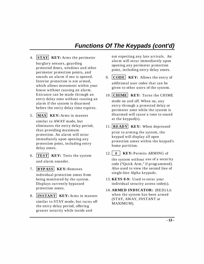
4. STAY KEY: Arms the perimeter
burglary sensors, guardingprotected doors, windows and otherperimeter protection points, andsounds an alarm if one is opened.Interior protection is not armed,which allows movement within yourhouse without causing an alarm.Entrance can be made through anentry delay zone without causing analarm if the system is disarmedbefore the entry delay time expires.
5. MAX KEY: Arms in manner
similar to AWAY mode, buteliminates the entry delay period,thus providing maximumprotection. An alarm will occurimmediately upon opening anyprotection point, including entrydelay zones.
6. TEST KEY: Tests the system
and alarm sounder.
7. BYPASS KEY: Removes
individual protection zones frombeing monitored by the system.Displays currently bypassedprotection zones.
8. INSTANT KEY: Arms in manner
similar to STAY mode, but turns offthe entry delay period, offeringgreater security while inside and
not expecting any late arrivals. Analarm will occur immediately uponopening any perimeter protectionpoint, including entry delay zones.
9. CODE KEY: Allows the entry of
additional user codes that can begiven to other users of the system.
10. CHIME KEY: Turns the CHIME
mode on and off. When on, anyentry through a protected delay orperimeter zone while the system isdisarmed will cause a tone to soundat the keypad(s).
11. READY KEY: When depressed
prior to arming the system, thekeypad will display all openprotection zones within the keypad'shome partition.
12. # KEY: Permits ARMING of
the system without use of a securitycode (“Quick Arm,” if programmed).Also used to view the second line ofsingle-line Alpha keypads.
13. KEYS 0-9: Used to enter yourindividual security access code(s).
14. ARMED INDICATOR: (RED) Litwhen the system has been armed(STAY, AWAY, INSTANT orMAXIMUM).

Functions Of The Keypads (cont'd)
- 14 -
15. INTERNAL SOUNDER: Source ofaudible internal warning andconfirmation sounds, as well asalarms (see "Summary of AudibleNotifications").
16. PANIC KEYS: Some keypads usekey pairs to activate panic alarms,rather than individual keys. Refer
To Panic Keys for descriptions ofthese keys.
IMPORTANT!When you use the keypad to enter codes andcommands, press the keys within 2 seconds ofone another. If 2 seconds elapse without a keydepression, the entry is aborted and must berepeated from its beginning.

- 15 -
Checking For Open Zones
Using the ✱ Key
Before arming your system, all protected doors, windows and otherprotection zones must be closed or bypassed (see “BypassingProtection Zones”). Otherwise the keypad will display a “NOTREADY” message. Using the [✱] key will display all zones that arefaulted, making it easier for you to secure any open zones.
NOTE: A green READY indicator (if present) on the keypad will be litif the system is ready to be armed. If not lit, the system is notready.
NOT READY - PRESS ✱TO SHOW FAULTS
To show faulted zones:
1. ✱ Press The [✱] KeyDo not enter security code, but simplypress the [✱] key.
2. FAULT 05 FRONTUPSTAIRS BEDROOM
Secure Faulted ZonesTypical fault display shows open zones.Secure or bypass the zones displayedbefore arming the system.
3. ***DISARMED***READY TO ARM
System Can Be ArmedThe “READY” message will be displayedwhen all protection zones have beeneither closed or bypassed.
You may now arm the system as usual.

- 16 -
Arming Perimeter Only(With Entry Delay ON)
Using the 3 KeySTAY
Use this key when you are staying home, but might expect someone touse the entrance door later.
When armed in STAY mode, the system will sound an alarm if aprotected door or window is opened, but you may otherwise movefreely throughout the premises. Late arrivals can enter through theentrance door without causing an alarm, but they must disarm thesystem within the entry delay period or an alarm will occur.
Close all protected perimeter windows and doors beforearming (see “Checking For Open Zones”). The green READYindicator (if present) on the keypad should be lit if the system is readyto be armed.
1. + 3 (Security Code) STAY
Enter Security Code, Then PressSTAY
Example: 7 2 9 6 then press the
STAY key
or for quick arming(if enabled)
Press The “#” followed by the “STAY”Key
2. ***ARMED STAY*** Listen For 3 BeepsThe keypad will beep three times and willdisplay the “ARMED STAY” message. Thered ARMED indicator also lights.
You can restart the exit delay at any time after arming in STAY mode
by pressing the ✴ key. This is useful if you wish to open the
entry/exit door to let someone in after arming the system and avoidshaving to disarm the system and then re-arm it again.

- 17 -
Arming Perimeter Only(With Entry Delay OFF)
Using the 7 KeyINSTANT
Use this key when you are staying home and do not expect anyone touse the entrance door.
When armed in INSTANT mode, the system will sound an alarm if aprotected door or window is opened, but you may otherwise movefreely throughout the premises. The alarm will also soundimmediately if anyone opens the entrance door. Close all protectedperimeter windows and doors before arming (See “Checking ForOpen Zones”). The green READY indicator (if present) on the keypadshould be lit if the system is ready to be armed.
1. + 7
(Security Code) INSTANT
Enter Security Code, Then PressINSTANT
Example: 7 2 9 6 then press the
INSTANTor for quick arming(if enabled)
Press The “#” followed bythe“INSTANT” Key
2. ARMED * INSTANT*YOU MAY EXIT NOW
Listen For 3 BeepsThe keypad will beep three times and willdisplay the “ARMED INSTANT” message.The red ARMED indicator also lights.
You can restart the exit delay at any time after arming in INSTANTmode by pressing the ✴✴ key. This is useful if you wish to open the
entry/exit door to let someone in after arming the system and avoidshaving to disarm the system and then re-arm it again.
- 18 -
Arming All Protection(With Entry Delay ON)
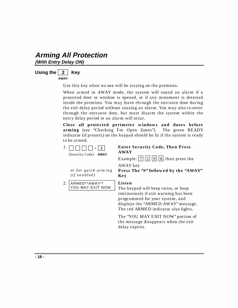
Using the 2 KeyAWAY
Use this key when no one will be staying on the premises.
When armed in AWAY mode, the system will sound an alarm if aprotected door or window is opened, or if any movement is detectedinside the premises. You may leave through the entrance door duringthe exit delay period without causing an alarm. You may also re-enterthrough the entrance door, but must disarm the system within theentry delay period or an alarm will occur.
Close all protected perimeter windows and doors beforearming (see “Checking For Open Zones”). The green READYindicator (if present) on the keypad should be lit if the system is readyto be armed.
1. + 2
(Security Code) AWAY
Enter Security Code, Then PressAWAY
Example: 7 2 9 6 then press the
AWAY keyor for quick arming(if enabled)
Press The “#” followed by the “AWAY”Key
2. ARMED**AWAY**YOU MAY EXIT NOW
ListenThe keypad will beep twice, or beepcontinuously if exit warning has beenprogrammed for your system, anddisplays the “ARMED AWAY” message.The red ARMED indicator also lights.
The “YOU MAY EXIT NOW” portion ofthe message disappears when the exitdelay expires.

- 19 -
Arming All Protection(With Entry Delay OFF)
Using the 4 KeyMAXIMUM
Use this key when the premises will be vacant for extended periods oftime such as vacations, etc., or when no one will be moving throughprotected interior areas.When armed in MAXIMUM mode, the system will sound an alarm if aprotected door or window is opened, or if any movement is detectedinside the premises. You may leave through the entrance door duringthe exit delay period without causing an alarm, but an alarm will besounded as soon as someone re-enters.Close all protected perimeter windows and doors beforearming (see “Checking For Open Zones”). The green READYindicator (if present) on the keypad should be lit if the system is readyto be armed.1. + 4
(Security Code) MAXIMUM
Enter Security Code, Then PressMAXIMUM
Example: 7 2 9 6 then press the
MAXIMUM key
or for quick arming(if enabled)
Press The “#” followed by the“MAXIMUM” Key
2. ARMED*MAXIMUM*YOU MAY EXIT NOW
ListenThe keypad will beep twice, or beepcontinuously if exit warning has beenprogrammed for your system, and willdisplay the “ARMED MAXIMUM”message (“AWAY/INSTANT” on fixed-word keypads). The red ARMED indicatoralso lights.The “YOU MAY EXIT NOW” portion ofthe message disappears when the exitdelay expires.

- 20 -
Disarming And Silencing Alarms
Using the 1 KeyOFF
Use the OFF key to disarm the system and to silence alarm andtrouble sounds. See “Summary Of Audible Notification” forinformation which will help you to distinguish between fire andburglary alarm sounds.
IMPORTANT: If you return and the main burglarysounder is on, DO NOT enter the premises, but call thepolice from a nearby safe location. If you return after analarm has occurred and the main sounder has shutitself off, the keypad will beep rapidly upon entering,indicating that an alarm has occurred during yourabsence and an intruder may still be on the premises.LEAVE IMMEDIATELY and CONTACT THEPOLICE from a nearby safe location.
To disarm the system and silence burglary alarms:
1. + 1
(Security Code) OFF
Enter Security Code, Then Press OFF
Example: 7 2 9 6 then press the
OFF key
2. **DISARM**READY TO ARM
Listen For 1 BeepThe “READY” message will be displayed(if no alarms have occurred while armed)and the keypad will beep once to confirmthat the system is disarmed.
Memory of Alarm
If an alarm occurs, the keypad displays the zone number(s) thatcaused the alarm and the type of alarm. These messages remaindisplayed until cleared by a user.

Disarming And Silencing Alarms (cont'd)
- 21 -
To clear the display:
Note the zone number displayed and enter an OFF sequence.
+ 1
(Security Code) OFF
Enter Security Code, Then Press OFF
Example: 7 2 9 6 then press the
OFF key
If the “READY” message will not display, go to the displayed zone andcorrect the fault (close windows, etc.). If the fault cannot be corrected,notify your alarm company.
- 22 -
Bypassing Protection Zones
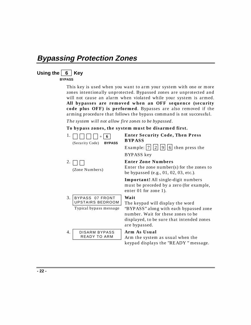
Using the 6 KeyBYPASS
This key is used when you want to arm your system with one or morezones intentionally unprotected. Bypassed zones are unprotected andwill not cause an alarm when violated while your system is armed.All bypasses are removed when an OFF sequence (securitycode plus OFF) is performed. Bypasses are also removed if thearming procedure that follows the bypass command is not successful.
The system will not allow fire zones to be bypassed.
To bypass zones, the system must be disarmed first.
1. + 6
(Security Code) BYPASS
Enter Security Code, Then PressBYPASS
Example: 7 2 9 6 then press the
BYPASS key
2.
(Zone Numbers)
Enter Zone NumbersEnter the zone number(s) for the zones tobe bypassed (e.g., 01, 02, 03, etc.).
Important! All single-digit numbersmust be preceded by a zero (for example,enter 01 for zone 1).
3. BYPASS 07 FRONTUPSTAIRS BEDROOM
Typical bypass message
WaitThe keypad will display the word“BYPASS” along with each bypassed zonenumber. Wait for these zones to bedisplayed, to be sure that intended zonesare bypassed.
4. DISARM BYPASSREADY TO ARM
Arm As UsualArm the system as usual when thekeypad displays the "READY ” message.

Bypassing Protection Zones (cont'd)
- 23 -
Quick Bypass
Your system may allow you to easily bypass all open (faulted) zoneswithout having to enter zone numbers individually. Ask your installerif this feature is active.
1. + 6
(Security Code) BYPASS
Enter Security Code, Then PressBYPASSExample: 7 2 9 6 then press the
BYPASS key
2. BYPASS 07 FRONTUPSTAIRS BEDROOM
Typical bypass message
WaitIn a few moments, all open zones will bedisplayed along with the word “BYPASS.”Wait for these zones to be displayedbefore arming. Arming the system beforezones are displayed eliminates allbypasses.
3. DISARM BYPASSREADY TO ARM
Arm As UsualArm the system as usual when thekeypad displays the "READY ” message.
Displaying Bypassed Zones
For determining what zones have been previously bypassed. Bypassedzones can be displayed only when the system is disarmed, and whenthe “Bypass” message shown in step 3 above is displayed.
1. + 6
(Security Code) BYPASS
Enter Security Code, Then PressBYPASSExample: 7 2 9 6 then press the
BYPASS key
2. BYPASS 07 FRONTUPSTAIRS BEDROOM
Typical bypass message
WaitIn a few moments, all open zones will besequentially displayed along with theword “BYPASS.”

- 24 -
Chime Mode
Using the 9 KeyCHIME
Your system can be set to alert you to the opening of a door orwindow† while it is disarmed by using CHIME mode. When activated,three beeps will sound at the keypad whenever a protected perimeterdoor or window is opened.
† Or selected doors or windows if chime-by-zone feature isactive. Ask installer if this feature applies to your system.
Pressing the ✱ key will display the open protection points.
Note that the CHIME mode can be activated only when the system isdisarmed.
To turn CHIME mode on:
1. + 9
(Security Code) CHIME
Enter Security Code, Then PressCHIME
Example: 7 2 9 6 then press the
CHIME key
2. DISARM CHIMEREADY TO ARM
ViewThe “CHIME” message displays whileCHIME mode is on.
To turn CHIME mode off:
1. + 9
(Security Code) CHIME
Enter Security Code, Then PressCHIME
Example: 7 2 9 6 then press the
CHIME key
2. **DISARM**READY TO ARM
ViewThe “CHIME” message disappears fromthe display.

- 25 -
Panic Keys(For Manually Activating Silent And/Or Audible Alarms)
Using Panic KeysYour system may have been programmed to use special keys tomanually activate panic functions. The functions that might beprogrammed are listed below. See your installer for the function(s)that may have been programmed for your system.
Your installer should note the functions that are active in your system.
ACTIVE PANIC FUNCTIONSKEYS ZONE FUNCTION1 and ✱ 953 and # 96✱ and # 99A 95B 99C 96To use a paired key panic function, simply press both keys of theassigned pair at the same time. If your keypad has lettered keys forpanic functions, press the designated key and hold down for at least 2seconds to activate the panic function.
Types of Panic AlarmsA silent emergency sends an alarm signal to the alarm monitoringcompany,* but there will be no audible alarms or visual displays.An audible emergency sends an emergency message to the alarmmonitoring company* and sounds a loud, steady alarm at your keypadand at any external sounders that may be connected (“ALARM” plusa zone number is also displayed).A personal emergency alarm sends an emergency message to thealarm monitoring company* and sounds at keypads, but not atexternal sounders (“ALARM” plus a zone number is also displayed).A fire alarm sends a fire alarm message to the alarm monitoringcompany* and uniquely activates keypad and any external sounders(“FIRE” plus a zone number is also displayed).
*If your system is connected to an alarm monitoring company

- 26 -
Using Device Commands
General Information
Your system may be set up so that certain lights or other devices canbe turned on or off by using the device command from the keypad.Ask your installer if this has been done in your system. Ifprogrammed for your system, some devices may activateautomatically upon certain system conditions. In this case, thefollowing commands can be used to override the device activation. Seeyour installer for a full explanation of this feature.
To Activate Devices
Enter Security Code, Then Press # + 7 + Device Number
+ # + 7 + (Security Code) (Device Number)
Example: 7 2 9 6 then press #, then press 7, then enter the
number representing the device you wish to activate. See yourinstaller for device numbers assigned for your system.
To Deactivate Devices
Enter Security Code, Then Press # + 8 + Device Number
+ # + 8 + (Security Code) (Device Number)
Example: 7 2 9 6 then press #, then press 8, then enter the
number representing the device you wish to deactivate. See yourinstaller for device numbers assigned for your system.
Device Device #/Description Device Device #/Description1 52 63 74 8

- 27 -
Paging Feature
General Information
If the Paging feature has been programmed for your system, yourpager will respond to certain conditions as they occur in your system.This message appears in a 7-digit format explained below. You canalso send up to 16 additional digits that may consist of PIN numbers,messages, reminders, etc. These 16 digits are programmed by yourinstaller and will appear before the standard 7-digit message.
Code Format
The 7-digit condition code that follows takes the following form: SSS-00EE
SSS = 3-digit event code: 911 = Alarm811 = Trouble101 = Opening (disarm)102 = Closing (arm AWAY)
00EE = The first 2 digits will always be 00 followed by the 2-digituser number or zone number depending on the event code.
Examples
Pager displays: 911–0004 . This indicates that your system is
reporting an alarm (911) due to a fault in zone 4 (04). Alarm orTrouble codes are always followed by the zone numbers in whichthey occur.
Pager displays: 101–0011 . This indicates that your system is
reporting an open (101) by user 11 (0011). Opening or closing codesare always followed by the code number of the person who caused it tohappen. User codes are individually assigned and programmed intothe system by your installer.

- 28 -
Using The Keyswitch
General Information
Your system is equipped with a keyswitch for use when arming anddisarming. Red and green lights on the keyswitch plate indicate thestatus of your system as follows:
Green Light: This indicator lights when the system is disarmedand ready to be armed (no open zones). If the systemis disarmed and the green light is off, it indicates thesystem is not ready (one or more zones are open).
Red Light: This indicator lights when the system is armed ormemory of alarm exists.Lit Steady: System is armed in AWAY mode.
Slow Flashing: System is armed in STAY mode.
Rapid Flashing: Memory of alarm, indicating analarm has occurred.
Arming/ Disarming
To arm in the AWAY mode, turnthe key to the right for 1/2 second andrelease. Keypad will beep twice andthe red light will stay on steady.
To arm in the STAY mode, turnthe key to the right and hold forlonger than 1 second, then release.Keypad will beep three times and thered light will flash slowly.
To disarm the system, turn the keyto the right and release. If an alarmhas occurred, the red light will beflashing rapidly (memory of alarm).
GREEN RED

- 29 -
Security Codes
General Information
As an additional safety feature, other users who do not have a need toknow your code can be assigned different security codes. Thesesecondary users are identified by "user numbers," which are selectedwhen assigning a user's security code. You can assign up to 14additional user codes (user numbers 03-16), including the babysitterand duress codes. Note that the master (primary) user of the systemis the only one who can assign codes to secondary (or temporary)users, and is user number 02; user number 01 is reserved for theinstaller of the system.
All codes can be used interchangeably when performing systemfunctions (a system armed with one user's code can be disarmed byanother user's code), with the exception of the babysitter codedescribed below.
Babysitter Code
This code can be used to arm the system, but cannot disarm thesystem unless the system was armed with this code. This code istypically assigned to someone (such as a babysitter) who has a need toarm/disarm the system only at certain times. The babysitter code isassigned to user 15. The user of this code should not use the QuickArming feature described below.
Duress Code
This feature is intended for use when you are forced to disarm or armthe system under threat. When used, the system will act normally,but can silently notify the alarm monitoring company of yoursituation, if that service has been provided. Duress code is assigned touser 16.
Important: This code is useful only when the system is connected toa alarm monitoring company.
Security Codes (cont’d)
- 30 -
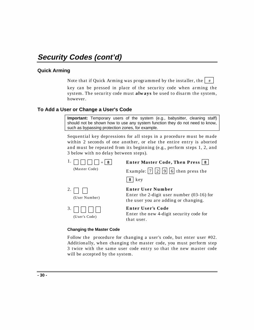
Quick Arming
Note that if Quick Arming was programmed by the installer, the #
key can be pressed in place of the security code when arming thesystem. The security code must always be used to disarm the system,however.
To Add a User or Change a User's Code
Important: Temporary users of the system (e.g., babysitter, cleaning staff)should not be shown how to use any system function they do not need to know,such as bypassing protection zones, for example.
Sequential key depressions for all steps in a procedure must be madewithin 2 seconds of one another, or else the entire entry is abortedand must be repeated from its beginning (e.g., perform steps 1, 2, and3 below with no delay between steps).
1. + 8
(Master Code)
Enter Master Code, Then Press 8
Example: 7 2 9 6 then press the
8 key
2. (User Number)
Enter User NumberEnter the 2-digit user number (03-16) forthe user you are adding or changing.
3. (User's Code)
Enter User's CodeEnter the new 4-digit security code forthat user.
Changing the Master Code
Follow the procedure for changing a user's code, but enter user #02.Additionally, when changing the master code, you must perform step3 twice with the same user code entry so that the new master codewill be accepted by the system.

Security Codes (cont'd)
- 31 -
To Delete a User
1. + 8
(Master Code)
Enter Master Code, Then Press 8
Example: 7 2 9 6 then press the
8 key
2. (User Number)
Enter User NumberEnter the 2-digit user number (03-16) forthe user whose code you are deleting.
3. ----------- StopWait (about 3 seconds) until the keypadbeeps once before pressing any other key.The code is automatically deleted.

- 32 -
Testing The System(TO BE CONDUCTED WEEKLY)
Using the 5 KeyTEST
The TEST key puts your system into a TEST mode, which allows eachprotection point to be checked for proper operation. The keypadsounds a single beep every 40 seconds as a reminder that the systemis in this TEST mode.
Note: An alarm message will not be sent to your alarm monitoringcompany during the following tests.
1. **** DISARM****READY TO ARM
Disarm The SystemDisarm the system and close all protectedwindows, doors, etc. The “READY”message should be displayed and thegreen READY indicator (if present on thekeypad) should also be lit.
2. + 5
(Security Code) TEST
Enter Security Code, Then PressTEST
Example: 7 2 9 6 then press the
TEST key
3. Listen. The external sounder shouldsound for 2 seconds and then turn off.If the sounder does not sound, CALLFOR SERVICE IMMEDIATELY.
4. Fault Zones. Open each protected doorand window in turn and listen for threebeeps from the keypad. Identification ofeach faulted protection point shouldappear on the display. The display willclear when the door or window is closed.
Walk in front of any interior motion

Testing The System (cont'd)
- 33 -
detectors (if used) and listen for threebeeps. The identification of the detectorshould appear on the display when it isactivated. The display will clear when nomotion is detected. Note that if wirelessmotion detectors are used, there is a 3-minute delay between activations. This isto conserve battery life.
To test all smoke detectors, follow themanufacturer's instructions. Theidentification of each detector shouldappear on the display when each isactivated.
If a problem is experienced with anyprotection point (no confirming sounds, nodisplay), CALL FOR SERVICEIMMEDIATELY.
When all protection points have beenchecked and are intact (closed), thereshould be no zone identification numbersdisplayed on the keypad.
When testing is completed, exit the TESTmode by continuing with step 5.
5. + 1
(Security Code) OFF
Exit TEST ModeEnter your security code and press theOFF key.
If the test mode is inadvertently leftactive, it automatically turns off afterapproximately 4 hours.

- 34 -
Trouble Conditions
Typical “Check” Displays
The word “CHECK” on the keypad's display, accompanied by a rapidbeeping at the keypad, indicates that there is a trouble condition inthe system. The displays in parenthesis may appear on non-alphakeypads when the associated trouble condition is present.
To silence the beeping sound for “check” conditions, press any key.
CHECK + ZoneDescriptors
Indicates that a problem exists with thosezone(s)*. First, determine if the zone(s)displayed are intact and make them so if theyare not. If the zone uses a wireless detector,check that changes in the room (movingfurniture, televisions, etc.) are not blockingwireless signals from the detector. If theproblem has been corrected, the zonedescriptor(s) and “CHECK” should disappear.If not, key an OFF sequence (security code plusOFF) to clear the display. A “Check” conditioncan also indicate a wiring problem. If the“CHECK” display persists, CALL FORSERVICE IMMEDIATELY.
Note that the system will not allow arming if a“Check” condition exists. To arm the systemwith a “Check” condition present, you mustfirst bypass the zone(s) having the “Check”condition.
NOTE: Zone number 9 represents a problemwith wireless receivers or other system devices,which are not user-serviceable. CALL FORSERVICE IMMEDIATELY.

Trouble Conditions (cont'd)
- 35 -
Telco Fault(or CHECK andzone 94)
If the telephone line monitor feature has beenprogrammed for your system, this displayindicates that the telephone line has beendisconnected or cut. In some systems, thisdisplay will be accompanied by a trouble soundfrom the keypad and the external sounder maybe activated. CONTACT YOUR SERVICECOMPANY IMMEDIATELY.
To silence the trouble sound, enter yoursecurity code plus OFF.
COMM. FAILURE(or FC)
Indicates that a failure has occurred in thetelephone communication portion of yoursystem. CALL FOR SERVICE IMMEDI-ATELY.
SYSTEM LO BAT(or BAT with nozone No.)
Indicates that a low system battery conditionexists, accompanied by a once-per-minute"beeping"* at the keypad. CALL FORSERVICE IMMEDIATELY.
*The beeping that accompanies a low batterydisplay can be stopped by entering an OFFsequence (security code + OFF).
LO BAT + zonedescriptor (or BATwith zone No.)
Indicates that a low battery condition exists inthe wireless transmitter** displayed, andaccompanied by a once-per-minute beeping atthe Keypad. CALL FOR SERVICEIMMEDIATELY.
** Not all systems use wireless transmitters.
MODEM COMM(or CC)
Indicates that the control is on-line with thecentral station's remote computer. The controlwill not operate while on-line. Wait a fewminutes. The display should disappear.

Trouble Conditions (cont’d)
- 36 -
POWER indicator(if present) is off.AC LOSS isdisplayed
The system is operating on battery power only.If only some lights are out on the premises,check circuit breakers and fuses and reset orreplace as necessary. CALL FOR SERVICEIMMEDIATELY if AC power cannot berestored to the system.
Busy-Standby (ordI)
If this remains displayed for more than 1minute, system is disabled. CALL FORSERVICE AT ONCE.
OPEN CIRCUIT(or OC)
The keypad is not receiving signals from thecontrol. CALL FOR SERVICE AT ONCE.
Long Rng Trbl (orbF)
If programmed, backup Long Range Radiocommunication has failed. CALL FORSERVICE AT ONCE.
Bell failure (orCHECK 70)
Bell/Siren supervision failure. CALL FORSERVICE AT ONCE.
- 37 -
Fire Alarm System(If Installed)
General Information
Your fire alarm system (if installed) is active 24 hours a day,providing continuous protection. In the event of an emergency, theinstalled smoke and heat detectors will automatically activate yoursecurity system, triggering a loud, interrupted sound from thekeypad. An interrupted sound will also be produced by optionalexterior sounders. A “FIRE” message (with zone location) will appearat your keypad and remain on until you silence and clear the alarmdisplay.
In Case Of Fire
1. Should you become aware of a fire emergency before your detectorssense the problem, go to your nearest keypad and press the singlepanic key (or panic key pair) assigned as FIRE emergency (ifprogrammed by the installer) and hold down for at least 2 seconds.The alarm will sound.
2. Evacuate all occupants from the premises.
3. If flames and/or smoke are present, leave the premises and notifyyour local Fire Department immediately.
4. If no flames or smoke are apparent, investigate the cause of thealarm. The zone descriptor of the zone(s) in an alarm condition willappear at the keypad.
Silencing A Fire Alarm
1. Silence the alarm by pressing the 1 OFF
key.
To clear the alarm display, enter your security code and press the 1 OFF
key again.

Fire Alarm System (cont’d)
- 38 -
2. If the keypad indicates a trouble condition after the second OFFsequence, check that smoke detectors are not responding to smoke-or heat-producing objects in their vicinity. Should this be the case,eliminate the source of heat or smoke.
3. If this does not remedy the problem, there may still be smoke inthe detector. Clear it by fanning the detector for about 30 seconds.
4. When the problem has been corrected, clear the display by entering
your code and pressing the 1
OFF key.

- 39 -
Recommendations For Proper Protection
THE FOLLOWING RECOMMENDATIONS FOR THE LOCATION OF FIREAND BURGLARY DETECTION DEVICES HELP PROVIDE PROPERCOVERAGE FOR THE PROTECTED PREMISES.
Recommendations For Smoke And Heat Detectors
With regard to the number and placement of smoke/heat detectors,we subscribe to the recommendations contained in the National FireProtection Association's (NFPA) Standard #72 noted below.
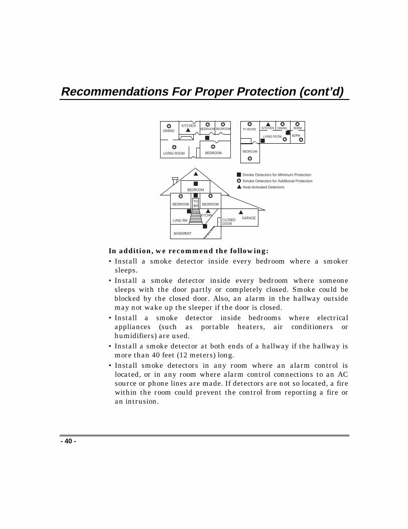
Early warning fire detection is best achieved by the installationof fire detection equipment in all rooms and areas of thehousehold as follows: For minimum protection a smoke detectorshould be installed outside of each separate sleeping area, andon each additional floor of a multi-floor family living unit,including basements. The installation of smoke detectors inkitchens, attics (finished or unfinished), or in garages is notnormally recommended.
For additional protection the NFPA recommends that you install heator smoke detectors in the living room, dining room, bedroom(s),kitchen, hallway(s), attic, furnace room, utility and storage rooms,basements and attached garages.
Recommendations For Proper Protection (cont’d)
- 40 -
DININGKITCHEN
BEDROOM
BEDROOM
BEDROOM
BEDROOM
LIVING ROOM
✪
✪
✪ ✪
✪
▲
▲
BEDROOM
BDRM
BDRM
DINING
LIVING ROOM
TV ROOM KITCHEN
■■
■
✪
✪
✪
✪ ✪
✪
▲
✪
✪
✪
BEDROOM BEDROOMTOBR
■
■
■
■
■
LVNG RM
BASEMENT
KTCHN▲
▲
. CLOSEDDOOR
GARAGE▲
Smoke Detectors for Minimum Protection
Smoke Detectors for Additional Protection
Heat-Activated Detectors
In addition, we recommend the following:• Install a smoke detector inside every bedroom where a smoker
sleeps.• Install a smoke detector inside every bedroom where someone
sleeps with the door partly or completely closed. Smoke could beblocked by the closed door. Also, an alarm in the hallway outsidemay not wake up the sleeper if the door is closed.
• Install a smoke detector inside bedrooms where electricalappliances (such as portable heaters, air conditioners orhumidifiers) are used.
• Install a smoke detector at both ends of a hallway if the hallway ismore than 40 feet (12 meters) long.
• Install smoke detectors in any room where an alarm control islocated, or in any room where alarm control connections to an ACsource or phone lines are made. If detectors are not so located, a firewithin the room could prevent the control from reporting a fire oran intrusion.

Recommendations For Proper Protection (cont'd)
- 41 -
Recommendations For Proper Intrusion Protection
For proper intrusion coverage, sensors should be located at everypossible point of entry to a home or commercial premises. This wouldinclude any skylights that may be present, and the upper windows ina multi-level building.
In addition, we recommend that radio backup be used in a securitysystem so that alarm signals can still be sent to the alarm monitoringstation in the event that the telephone lines are out of order (alarmsignals are normally sent over the phone lines, if connected to analarm monitoring station).

- 42 -
Emergency Evacuation
Establish and regularly practice a plan of escape in the event of fire. The followingsteps are recommended by the National Fire Protection Association:
1. Position your detector or your interior and/orexterior sounders so that they can be heard by alloccupants.
2. Determine two means of escape from each room.One path of escape should lead to the door thatpermits normal exit from the building. The othermay be a window, should your path be impassable.Station an escape ladder at such windows if there isa long drop to the ground.
3. Sketch a floor plan of the building. Show windows,doors, stairs and rooftops that can be used to escape.Indicate escape routes for each room. Keep theseroutes free from obstruction and post copies of theescape routes in every room.
4. Assure that all bedroom doors are shut while youare asleep. This will prevent deadly smoke fromentering while you escape.
5. Try the door. If the door is hot, check your alternateescape route. If the door is cool, open it cautiously.Be prepared to slam the door if smoke or heatrushes in.
6. Where smoke is present, crawl on the ground; do notwalk upright. Smoke rises and may overcome you.Clearer air is near the floor.
7. Escape quickly; don't panic.
8. Establish a common meeting place outdoors, away from your house, whereeveryone can meet and then take steps to contact the authorities and account forthose missing. Choose someone to assure that nobody returns to the house —many die going back.
•
FRONT
•
BACK
•
BATH
BEDROOM
KITCHEN
BACK DOOR
1 FLOORST
BEDROOM
2 FLOORND
BATH
BEDROOM
PORC
H
CLOSET
BEDROOM
BEDROOM

- 43 -
Maintaining Your System
Taking Care of Your System
The components of your security system are designed to be asmaintenance-free as possible. However, to make sure that yoursystem is in reliable working condition:
1. Test your system weekly.
2. Test your system after any alarm occurs (see “Testing TheSystem”).
Replacing Batteries in Wireless Sensors
Each wireless sensor in your system has a 9-volt or 3-volt battery. Thesystem detects a low battery in any wireless sensor, including smokedetectors, the optional personal emergency transmitter, and theoptional portable wireless keypad. (A low battery in a portablewireless keypad is detected as soon as one of its keys is pressed, andthe wired keypad will display “00. ”)
Alkaline batteries provide a minimum of 1 year of operation, and inmost units and applications, provide 2–4 years of service. 3-voltlithium batteries provide up to 4 or more years of operation. Actualbattery life will depend on the environment in which the sensor isused, the number of signals that the transmitter in the sensor hashad to send, and the specific type of sensor. Factors such as humidity,high or low temperatures or large swings in temperature may all leadto the reduction of actual battery life in an installation.
If you have a low battery in a wireless sensor, a “LOWBATTERY” message is displayed on the keypad.
In addition, a battery-operated smoke detector with a low battery alsoemits a single "chirp" sound approximately once every 20–30 seconds,identifying itself as the smoke detector with the weak battery.
Note: The “LOW BATTERY” message comes on as a warning thatbattery replacement in indicated sensor(s) is due within 30 days. In
Wirelesssensors maynot havebeen used inyour securitysystem

Maintaining Your System (cont’d)
- 44 -
the meantime, a sensor causing a low-battery indication is still fullyoperational.
Important: Use only batteries recommended by your installer asreplacement.
Silencing Low Battery Warning Tones at the Keypad
You can silence the keypad’s warning tones by pressing the 1 OFF
key,
but the keypad's “LOW BATTERY” message display will remain on asa reminder that you have a low-battery condition in one or more ofyour sensors. When you replace the weak battery with a fresh one, thesensor will send a "good battery" signal to the control as soon as thesensor is activated (opening/closing of door, window, etc.), causing the“LOW BATTERY” display to turn off. If the sensor is not activated,the display will automatically clear within approximately 1 hour.
Routine Care
• Treat the components of your security system as you would anyother electrical equipment. Do not slam sensor-protected doors orwindows.
• Keep dust from accumulating on the keypad and all protectivesensors, particularly on motion sensors and smoke detectors.
• The keypad and sensors should be cleaned carefully with a dry softcloth. Do not spray water or any other fluid on the units.

- 45 -
Quick Guide To System FunctionsFUNCTION PROCEDURE COMMENTSCheck Zones Press [✴] Do this to view faulted zones when system not
ready.Arm System Enter code or press #, then
Press arming key desired(AWAY, STAY, INSTANT,MAXIMUM)
Do this to arm the system in the mode selected.
Disarm System Enter codePress OFF [1]
Do this to disarm the system and silences alarms.
Bypass Zones Enter codePress [6]Enter zone numbers to be bypassed(use 2-digit entries)
Do this to bypass protection zones. Bypassed zonesare unprotected and will not cause an alarm ifviolated.
Quick Bypass Enter codePress [6] and stop
Do this to bypass all faulted zones automatically, ifprogrammed.
Chime Mode ON Enter codePress CHIME [9]
Do this to turn on CHIME mode. Keypad will sound ifdoors or windows are violated while systemdisarmed.
Chime Mode OFF Enter codePress CHIME [9]
Do this to turn CHIME mode off.
Test Mode ON Enter codePress [5]
Do this to enter TEST mode. Sounds alarm sounderand allows sensors to be tested.
Test Mode OFF Enter codePress OFF [1]
Do this to turn TEST mode off. System returns tonormal mode.
Add or Change aUser
Enter master codePress [8] keyEnter user's 2-digit user No.Enter code for that user
Do this to add or change a user code.
Delete a User Enter master codePress [8] keyEnter user number to bedeleted
Do this to delete a user code from the system.
Change a MasterCode
Enter master codePress [8] keyPress [0] + [2] (master user no.)Enter new 4-digit master codeEnter new master code again
Do this to change the existing master code.

- 46 -
Summary Of Audible Notification(Alpha Display Keypads)
SOUND CAUSE DISPLAYLOUD, INTERRUPTED*Keypad & External
FIRE ALARM FIRE is displayed; descriptor of zone in alarm isdisplayed.
LOUD, CONTINUOUS*Keypad & External
BURGLARY/AUDIBLEEMERGENCY ALARM
ALARM is displayed; descriptor of zone in alarm isalso displayed.
ONE SHORT BEEP(not repeated)Keypad only
a. SYSTEM DISARMb. SYSTEM ARMING ATTEMPT
WITH AN OPEN ZONE.c. BYPASS VERIFY
a. SYSTEM READY is displayed.b. The number and descriptor of the open protection
zone is displayed.c. Numbers and descriptors of the bypassed
protection zones are displayed (one beep is heardfor each zone displayed). Subsequently, thefollowing is displayed: ZONE BYPASSED SYSTEMREADY
ONE SHORT BEEP(once every 40 seconds)Keypad only
SYSTEM IS IN TEST MODE Opened Zone identifications will appear.
ONE BEEP(once every 40 seconds)Keypad only
LOW BATTERY AT ATRANSMITTER
LO BAT displayed with description of transmitter.
TWO SHORT BEEPSKeypad only
ARM AWAY OR MAXIMUM ARMED AWAY or ARMED MAXIMUM displayed.Red ARMED indicator lit.
THREE SHORTBEEPSKeypad only
a. ARM STAY OR INSTANT
b. ZONE OPENED WHILESYSTEM IS IN CHIME MODE.
a. ARMED STAY or ARMED INSTANT displayed.Red ARMED indicator lit.
b. CHIME displayed, descriptor of open protectionzone will be displayed if the [✱] key is pressed.
RAPID BEEPINGKeypad only
a. TROUBLE
b. MEMORY OF ALARM
a. CHECK displayed; descriptor of troubled protectionzone is displayed.
b. FIRE or ALARM is displayed; descriptor of zone inalarm is displayed.
c. BELL FAILUREd. SYSTEM LOW BATTERY
c. BELL FAILURE or CHECK 70 is displayed.d. SYSTEM LO BAT or BAT is displayed.
SLOW BEEPINGKeypad only
a. EXIT DELAY WARNING (ifprogrammed)
b. ENTRY DELAY WARNING
a. ARMED AWAY or ARMED MAXIMUM isdisplayed along with You May Exit Now.
b. DISARM SYSTEM OR ALARM WILL O CCUR isdisplayed.Exceeding the delay time without disarming causesalarm.
* If a bell is used as external sounder, fire alarm is pulsed ring; burglary/audible emergency is steady ring.

- 47 -
GlossaryThe following terms are used throughout the manual.
ARM/DISARM: "Armed" simply means that the burglary portion of your systemis turned ON and is in a state of readiness. "Disarmed" meansthat the burglary system is turned OFF, and must be rearmed tobecome operational. However, even in a "disarmed" state,"emergency" and "fire" portions of your system are stilloperational.
KEYPAD: This is the area on your keypad containing numberedpushbuttons similar to those on telephones or calculators. Thesekeys control the arming or disarming of the system, and performother functions which were previously described in this manual.
ZONE: A specific area of protection.
BYPASS: To disarm a specific area of burglary protection while leavingother areas operational.
DELAY ZONE: An area of protection containing doors most frequently used toenter or exit (typically, a front door, back door, or door from thegarage into the building). The delay zone allows sufficient timefor authorized entry or exit without causing an alarm. Consultyour installer for the entry and exit delay times that have beenset for your system during installation and record them in thespace provided in “Entry/Exit Delays.”
DAY/NIGHT ZONE: An area of protection whose violation causes a trouble indicationduring the disarmed (DAY) mode and an alarm during thearmed (NIGHT) mode.

- 48 -
UL NOTICE: This is a "GRADE A" system.
FEDERAL COMMUNICATIONS COMMISSION (FCC) Part 15 STATEMENTThis equipment has been tested to FCC requirements and has been found acceptable for use. TheFCC requires the following statement for your information:
This equipment generates and uses radio frequency energy and if not installed and used properly,that is, in strict accordance with the manufacturer's instructions, may cause interference to radioand television reception. It has been type tested and found to comply with the limits for a Class Bcomputing device in accordance with the specifications in Part 15 of FCC Rules, which are designedto provide reasonable protection against such interference in a residential installation. However,there is no guarantee that interference will not occur in a particular installation. If this equipmentdoes cause interference to radio or television reception, which can be determined by turning theequipment off and on, the user is encouraged to try to correct the interference by one or more of thefollowing measures:
•If using an indoor antenna, have a quality outdoor antenna installed.•Reorient the receiving antenna until interference is reduced or eliminated.•Move the receiver away from the control/communicator.•Move the antenna leads away from any wire runs to the control/communicator.•Plug the control/communicator into a different outlet so that it and the receiver are on different
branch circuits.
If necessary, the user should consult the dealer or an experienced radio/television technician foradditional suggestions.The user or installer may find the following booklet prepared by the Federal CommunicationsCommission helpful: "Interference Handbook." This booklet is available from the U.S. GovernmentPrinting Office, Washington, DC 20402.
The user shall not make any changes or modifications to the equipment unless authorized by theInstallation Instructions or User's Manual. Unauthorized changes or modifications could void theuser's authority to operate the equipment.
IN THE EVENT OF TELEPHONE OPERATIONAL PROBLEMSIn the event of telephone operational problems, disconnect the control by removing the plug from theRJ31X (CA38A in Canada) telephone wall jack. We recommend that your certified installerdemonstrate disconnecting the phones on installation of the system. Do not disconnect the phoneconnection inside the control/communicator. Doing so will result in the loss of your phone lines. If theregular phone works correctly after the control/communicator has been disconnected from the phonelines, the control/communicator has a problem and should be returned for repair. If upon disconnectionof the control/communicator, there is still a problem on the line, notify the telephone company thatthey have a problem and request prompt repair service. The user may not under any circumstances (inor out of warranty) attempt any service or repairs to the system. It must be returned to the factory oran authorized service agency for all repairs.

- 49 -
FEDERAL COMMUNICATIONS COMMISSION (FCC) Part 68 NOTICEThis equipment complies with Part 68 of the FCC rules. On the front cover of thisequipment is a label that contains, among other information, the FCC registration numberand ringer equivalence number (REN) for this equipment. If requested, this informationmust be provided to the telephone company.This equipment uses the following jacks:
An RJ31X is used to connect this equipment to the telephone network.The REN is used to determine the quantity of devices which may be connected to thetelephone line. Excessive RENs on the telephone line may result in the devices not ringingin response to an incoming call. In most, but not all areas, the sum of the RENs should notexceed five (5.0). To be certain of the number of devices that may be connected to the line,as determined by the total RENs, contact the telephone company to determine themaximum REN for the calling area.If this equipment causes harm to the telephone network, the telephone company will notifyyou in advance that temporary discontinuance of service may be required. If advance noticeis not practical, the telephone company will notify the customer as soon as possible. Also,you will be advised of your right to file a complaint with the FCC if you believe necessary.The telephone company may make changes in its facilities, equipment, operations, orprocedures that could affect the operation of the equipment. If this happens, the telephonecompany will provide advance notice in order for you to make the necessary modificationsin order to maintain uninterrupted service.If trouble is experienced with this equipment, please contact the manufacturer for repairand warranty information. If the trouble is causing harm to the telephone network, thetelephone company may request you remove the equipment from the network until theproblem is resolved.There are no user serviceable components in this product, and all necessary repairs mustbe made by the manufacturer. Other repair methods may invalidate the FCC registrationon this product.This equipment cannot be used on telephone company-provided coin service. Connection toParty Line Service is subject to state tariffs.This equipment is hearing-aid compatible.When programming or making test calls to an emergency number, briefly explain to thedispatcher the reason for the call. Perform such activities in the off-peak hours; such asearly morning or late evening.

- 50 -
WARNING!THE LIMITATIONS OF THIS ALARM SYSTEM
While this system is an advanced design security system, it does not offer guaranteed protectionagainst burglary or fire or other emergency. Any alarm system, whether commercial or residential, issubject to compromise or failure to warn for a variety of reasons. For example:
• Intruders may gain access through unprotected openings or have the technical sophistication tobypass an alarm sensor or disconnect an alarm warning device.
• Intrusion detectors (e.g., passive infrared detectors), smoke detectors, and many other sensingdevices will not work without power. Battery-operated devices will not work without batteries,with dead batteries, or if the batteries are not put in properly. Devices powered solely by AC willnot work if their AC power supply is cut off for any reason, however briefly.
• Signals sent by wireless transmitters may be blocked or reflected by metal before they reach thealarm receiver. Even if the signal path has been recently checked during a weekly test, blockagecan occur if a metal object is moved into the path.
• A user may not be able to reach a panic or emergency button quickly enough.
• While smoke detectors have played a key role in reducing residential fire deaths in the UnitedStates, they may not activate or provide early warning for a variety of reasons in as many as 35%of all fires, according to data published by the Federal Emergency Management Agency. Some ofthe reasons smoke detectors used in conjunction with this System may not work are as follows.Smoke detectors may have been improperly installed and positioned. Smoke detectors may notsense fires that start where smoke cannot reach the detectors, such as in chimneys, in walls, orroofs, or on the other side of closed doors. Smoke detectors also may not sense a fire on anotherlevel of a residence or building. A second-floor detector, for example, may not sense a first-floor orbasement fire. Moreover, smoke detectors have sensing limitations. No smoke detector can senseevery kind of fire every time. In general, detectors may not always warn about fires caused bycarelessness and safety hazards like smoking in bed, violent explosions, escaping gas, improperstorage of flammable materials, overloaded electrical circuits, children playing with matches, orarson. Depending upon the nature of the fire and/or the locations of the smoke detectors, thedetector, even if it operates as anticipated, may not provide sufficient warning to allow alloccupants to escape in time to prevent injury or death.
• Passive Infrared Motion Detectors can detect intrusion only within the designed ranges asdiagrammed in their installation manual. Passive Infrared Detectors do not provide volumetricarea protection. They do create multiple beams of protection, and intrusion can only be detected inunobstructed areas covered by those beams. They cannot detect motion or intrusion that takesplace behind walls, ceilings, floors, closed doors, glass partitions, glass doors, or windows.Mechanical tampering, masking, painting or spraying of any material on the mirrors, windows orany part of the optical system can reduce their detection ability. Passive Infrared Detectors sensechanges in temperature; however, as the ambient temperature of protected area approaches thetemperature range of 90° to 105°F, the detection performance can decrease.

- 51 -
WARNING!THE LIMITATIONS OF THIS ALARM SYSTEM (cont'd)
• Alarm warning devices such as sirens, bells or horns may not alert people or wake up sleepers ifthey are located on the other side of closed or partly open doors. If warning devices sound on adifferent level of the residence from the bedrooms, then they are less likely to waken or alertpeople inside the bedrooms. Even persons who are awake may not hear the warning if the alarm ismuffled by a stereo, radio, air conditioner or other appliance, or by passing traffic. Finally, alarmwarning devices, however loud, may not warn hearing-impaired people or waken deep sleepers.
• Telephone lines needed to transmit alarm signals from a premises to a central monitoring stationmay be out of service or temporarily out of service. Telephone lines are also subject to compromiseby sophisticated intruders.
• Even if the system responds to the emergency as intended, however, occupants may haveinsufficient time to protect themselves from the emergency situation. In the case of a monitoredalarm system, authorities may not respond appropriately.
• This equipment, like other electrical devices, is subject to component failure. Even though thisequipment is designed to last as long as 10 years, the electronic components could fail at any time.
The most common cause of an alarm system not functioning when an intrusion or fire occurs isinadequate maintenance. This alarm system should be tested weekly to make sure all sensors andtransmitters are working properly.
Installing an alarm system may make one eligible for lower insurance rates, but an alarm system isnot a substitute for insurance. Homeowners, property owners and renters should continue to actprudently in protecting themselves and continue to insure their lives and property.
We continue to develop new and improved protection devices. Users of alarm systems owe it tothemselves and their loved ones to learn about these developments.
SERVICING INFORMATIONYour local Bay Alarm dealer is the person best qualified to serviceyour alarm system. Arranging some kind of regular service programwith him is advisable.
Your local Bay Alarm dealer is:
Name:
Address: ____________________________________________________
_______________________________________________________
Phone:
- 52 -
CANADIAN DEPARTMENT OF COMMUNICATIONS (DOC)STATEMENT
NOTICEThe Canadian Department of Communications labelidentifies certified equipment. This certification means thatthe equipment meets certain telecommunications networkprotective, operational and safety requirements. TheDepartment does not guarantee the equipment willoperate to the user's satisfaction.
Before installing this equipment, users should ensure thatit is permissible to be connected to the facilities of thelocal telecommunications company. The equipment mustalso be installed using an acceptable method ofconnection. In some cases, the company's inside wiringassociated with a single-line individual service may beextended by means of certified connector assembly(telephone extension cord). The customer should beaware that compliance with the above conditions may notprevent degradation of service in some situations.
Repairs to certified equipment should be made by anauthorized Canadian maintenance facility designated bythe supplier. Any repairs or alterations made by the userto this equipment, or equipment malfunctions, may givethe telecommunications company cause to request theuser to disconnect the equipment.
Users should ensure for their own protection that theelectrical ground connections of the power utility,telephone lines and internal metallic water pipe system, ifpresent, are connected together. This precaution may beparticularly important in rural areas.
Caution: Users should not attempt to make suchconnections themselves, but should contact theappropriate electric inspection authority, or electrician, asappropriate.
The Load Number (LN) assigned to each terminal devicedenotes the percentage of the total load to be connectedto a telephone loop which is used by the device, toprevent overloading. The termination on a loop mayconsist of any combination of devices subject only to therequirement that the total of the Load Numbers of all thedevices does not exceed 100.
AVISL'étiquette du ministère des Communications du Canadaidentifie le matériel homologué. Cette étiquette certifie quele matériel est conforme à certaines normes de protection,d'exploitation et de sécurité des réseaux detélécommunications. Le ministère n'assure toutefois pasque le matériel fonctionnera à la satisfaction del'utilisateur.Avant d'installer ce matériel, l'utilisateur doit s'assurer qu'ilest permis de le raccorder aux installations de l'entrepriselocale de télécommunications. Le matériel doit égalementêtre installé en suivant une méthode acceptée deraccordement. Dans certains cas, les fils intérieurs del'entreprise utilisés pour un service individuel à la ligneunique peuvent être prolongés au moyen d'un dispositifhomologué de raccordement (cordon prolongateurtéléphonique interne). L'abonné ne doit pas oublier qu'ilest possible que la conformité aux conditions énoncées ci-dessus n'empèchet pas la dégradation du service danscertaines situations. Actuellement, les entreprises detélécommunications ne permettent pas que l'on raccordeleur matériel aux prises d'abonnés, sauf dans les casprecis prévus par les tarifs particuliers de ces entreprises.Les réparations du matériel homologué doivent êtreeffectuées pas un centre d'entretien canadien autorisédésigné par le fournisseur. La compagnie detélécommunications peut demander à l'utilisateur dedébrancher un appareil à la suite de réparations ou demodifications effectuées par l'utilisateur ou à cause demauvais fonctionnement.Pour sa propre protection, l'utilisateur doit s'assurer quetous les fils de mise en terre de la source d'énergieélectrique, des lignes téléphoniques de réseau deconduites d'eau s'il y en a, soient raccordés ensemble.Cette précaution est particulièrement importante dans lesrégions rurales.Avertissement: L'utilisateur ne doit pas tenter de faireces raccordements lui-même il doit avoir recours à unservice d'inspection des installations électriques, ou à unélectricien, selon le cas.L'indice de charge (IC) assigné à chaque dispositifterminal pour éviter toute surcharge indique lepourcentage de la charge totale qui peut être raccordé àun circuit téléphonique bouclé utilisé par ce dispositif. Laterminaison du circuit bouclé peut être constituée den'importe quelle combinaison de dispositifs, pourvu que lasomme des indices de charge de l'ensemble desdispositifs ne dépasse pas 100.

- 53 -
OWNER’S INSURANCE PREMIUM CREDIT REQUESTThis form should be completed and forwarded to your homeowner’s insurance carrier for possiblepremium credit.
A. GENERAL INFORMATION:Insured’s Name and Address:
Insurance Company: Policy No.:
VISTA-20BAY Other ______________________________
Type of Alarm: Burglary Fire Both
Installed by: Serviced by: Name Name
Address Address
B. NOTIFIES (Insert B = Burglary, F = Fire)Local Sounding Device Police Dept. Fire Dept.
Central Station Name:
Address:
Phone:
C. POWERED BY: A.C. With Rechargeable Power Supply
D. TESTING: Quarterly Monthly Weekly Other
continued on other side

- 54 -
OWNER’S INSURANCE PREMIUM CREDIT REQUEST(cont.)
E. SMOKE DETECTOR LOCATIONS
Furnace Room Kitchen Bedrooms Attic
Basement Living Room Dining Room Hall
F. BURGLARY DETECTING DEVICE LOCATIONS:
Front Door Basement Door Rear Door All Exterior Doors
1st Floor Windows All windows Interior locations
All Accessible Openings, Including Skylights, Air Conditioners and Vents
G. ADDITIONAL PERTINENT INFORMATION:
Signature: Date:

- 55 -
Index2-line Alpha Keypad .................................... 9AC Loss ..................................................... 36Add A User ................................................ 30Alarm ......................................................... 11Alpha Keypad .............................................. 9Audible Emergency ....................... 11, 25, 46Away.......................... 4, 5, 10, 14, 18, 28, 45Away Mode.......................................... 18, 28Babysitter Code......................................... 29Beeping ..................................... 7, 34, 35, 46Burglary Protection .............. 4, 10, 12, 13, 47Bypassing Zones....................................... 22Check ...................................... 15, 34, 45, 46Chime ...................................... 11, 24, 45, 46Chime Mode .................................. 13, 24, 45Comm. Failure ........................................... 35Delete A User ...................................... 31, 45Disarming ...................................... 20, 28, 47Displaying Bypassed Zones ...................... 23Duress Code.............................................. 29Emergency Evacuation.............................. 42Entry Delay .............. 7, 10, 16, 17, 18, 19, 46Exit Alarm .................................................... 7Exit Delay .................................. 7, 16, 17, 46Fire Alarm...................................... 11, 25, 37Fire Protection ............................................. 5Fire Zone ............................................. 11, 22Fixed Word Keypad............................... 9, 12Fixed Word Keypad Display ...................... 10Instant.......................................................... 4Key Functions............................................ 12Keypads................................................. 9, 12
Lo Bat ..................................................35, 46Low Battery....................................11, 35, 43Maximum ...............................................4, 19Maximum Mode .........................................19Memory of Alarm .......................6, 20, 28, 46Modem Comm ...........................................35National Fire Protection Association....39, 42Not Ready................................10, 14, 15, 45OFF............................................................22Off Key...........................................20, 33, 35Paging Feature ......................................6, 27Panic Alarm ...............................................25Panic Functions .........................................25Panic Keys.................................................25Personal Emergency ...........................25, 43Quick Arming ...............16, 17, 18, 19, 29, 30Security Codes ......................................5, 29Silence Alarm.............................................20Silent Emergency.......................................25Sounder .................................5, 9, 14, 32, 35Stay................................4, 10, 14, 16, 28, 45System Overview.........................................4Telco Fault .................................................35Temporary Users.......................................30Test Key.....................................................32Test Mode............................................32, 45Trouble Conditions.....................................34User Number .......................................27, 29Voice Module ...............................................6Wireless Sensor.........................................43Zones...........................................................4

¬1������1lN7527-4 03/98
SINCE 1946
BAY ALARM925 Ygnacio Valley RoadWalnut Creek, CA 94596


