ModelNo.PFTL73105.2 Seda!No. SeriaU DecaU Asa manufacturer, we are com- mitted to providing complete customer satisfaction, if you have questions, or if parts are damaged or missing, PLEASE CONTACT OUR CUSTOMER SERVICE DEPARTMENT DIRECTLY. CALL TOLL-FREE: 1-888-533-1333 Mon.=Fd., 6 a.m.=6 p.m. MST ON THE WEB: www.proformservice.com CAUTION Read all precautions and instruc- tions in this manual before using this equipment. Save this manual for future reference. 'S www.proform.com new products, prizes, fitness tips, and much more[
Transcript
ModelNo.PFTL73105.2Seda!No.
SeriaUDecaU
Asa manufacturer,we are com-mitted to providing completecustomer satisfaction, if youhave questions, or if parts aredamaged or missing, PLEASECONTACT OUR CUSTOMERSERVICE DEPARTMENTDIRECTLY.
CALL TOLL-FREE:
1-888-533-1333Mon.=Fd., 6 a.m.=6 p.m. MST
ON THE WEB:www.proformservice.com
CAUTION
Read all precautions and instruc-tions in this manual before usingthis equipment. Save this manualfor future reference.
'S
www.proform.com
new products, prizes,fitness tips, and much more[
TABLE OF CONTENTS
iMPORTANT PRECAUTIONS ................................................................ 3
BEFORE YOU BEGIN ...................................................................... 5ASSEMBLY ............................................................................... 6OPERATHON AND ADJUSTMENT ............................................................ 10HOW TO FOLD AND MOVE THE TREADMHLL .................................................. 20
TROUBLESHOOTHNG ..................................................................... 22CONDiTiONiNG GUiDELiNES ............................................................... 24PART LiST .............................................................................. 26
ORDERHNG REPLACEMENT PARTS .................................................. Back Cover
Note: An EXPLODED DRAWING is attached in the center of this manual,
PROFORM is a registered trademark of HCON HP,Hnc,
2
iMPORTANT PRECAUTIONS
WARN ING: Toreducethe.okofburns,f re,eJect.eshock,or,njurytopereons,readthefollowing important precautions and information before operating the treadmi&
1. It is the responsibility of the owner to ensurethat all users of this treadmill are adequatelyinformed of all warnings and precautions.
2. Use the treadmill only as described.
3. Place the treadmill on a leveJ surface, with atleast eight feet of clearance behind it and twofeet on each side. Do not place the treadmillon any surface that bJocks air openings. Toprotect the floor or Carpet from damage, placea mat under the treadmi&
4. Keep the treadmill indoors, away from mois-ture and dust. Do not put the treadmill in agarage or covered patio, or near water.
5. De not operate the treadmill where aerosolproducts are used or where oxygen is beingadministered.
& Keep children under the age of 12 and petsaway from the treadmill at all times.
7. The treadmill should be used only by personsweighing 300 pounds or less.
or see your loeaJ electronics store.
12. Failure to use a properly functioning surgesuppressor could result in damage to the con-trol system of the treadmill. If the control sys-tem is damaged, the walking beJt may changespeed, accelerate, or stop une×pectedJy,which may result in a fall and serious injury.
13. Keep the power cord and the surge suppres-sor away from heated surfaces.
14. Never move the walking belt while the poweris turned off. Do not operate the treadmill ifthe power cord or pJug is damaged, or if thetreadmill is not working properly. (See TROU-BLESHOOTmNG on page 22 if the treadmill isnot working property.)
15. Read, understand, and test the emergencystop procedure before using the treadmill (seeOPERATION AND ADJUSTMENT on page 10).
l& Never start the treadmilJ whiJe you are stand-ing on the walking beJt. Always hoJd thehandrails while using the treadmill
9=
Never allow more than one person on thetreadmill at a time.
Wear appropriate exercise clothes whenusing the treadmill Do not wear loose clothesthat could become caught in the treadmill.AtHetic support clothes are recommended forboth men and women. A/ways wear athleticshoes. Never use the treadmillwith bare feet,
wearing onlystockings,ofinsandals.
17. The treadmill is capable of high speeds.Adjust the speed in small increments to avoidsudden jumps in speed.
18. The pulse sensor is not a medical device.Various factors, including the user's move-meat, may affect the accuracy of heart ratereadings. The puJse sensor is intended onlyas an exercise aid in determining heart ratetrends in general
10. When connecting the power cord (see page10), plug the power cord into a surge sup-pressor (not included) and pJug the surgesuppressor into a grounded circuit capabJe ofcarrying !5 or more stops. No other applianceshould be on the same circuit. Do not use anextension cord.
11. Use only a singJe-outiet surge suppressorthat meets aH of the specifications describedon page 10. To purchase a surge suppressor,see your local PROFORM dealer or call thetoll-free telephone number on the front coverof this manual and order part number 146148,
19. Never leave the treadmill unattended while itis running. Always remove the key, unplugthe power cord, and switch the reset/off ciPcuit breaker to the off position when thetreadmill is not in use. {See the drawing onpage 5 for the location of the circuit breaker.)
20. Do not attempt to raise, lower, or move thetreadmill until it is properly assembled. (SeeASSEMBLY on page & and HOW TO FOLDAND MOVE THE TREADMILL on page 20.)You must be able to safely Hft 45 pounds (20kg) to raise, tower, or move the treadmill.
21.When folding or moving the treadmill, makesure that the storage latch is fully dosed°
22. Inspect and properly tighten all parts of thetreadmill regularly.
23. Never insert any object into any opening.
24.DANGER: Always_nplugthepower
treadmill, and before performing the mainte=nance and adjustment procedures described inthis manual. Never remove the motor hood un-
less instructed to do so by an authorized ser-vice representative. Servicing other than theprocedures in this manual should be performedby an authorized service representative only.
25. This treadmill is intended for in=home use
cord immediately after use, before cleaning the onJy. Do not use this treadmill in a commer=ciaL rental or institutional setting.
_WAF_N ING: Beforebeginningth_soranyexerciseprogram,consultyourphye_e_an.Th_sis especially important for persons over the age of 35 or persons with pro=existing health problems.Read all instructions before using, iCON assumes no responsibility for personal injury or propertydamage sustained by or through the use of this product.
SAVE THESE INSTRUCTmONS
The decals shown here have been placed on the treadmill, ifa decal is missing, or if it is not JegibJe, call the toll-free tele-phone number on the front cover of this manuaJ and order afree replacement decal Apply the decal in the tocationshown.
f _% fJ_g_lsan_haJr
br,lt
o fix the belt whileisn ovr,g
,Alwa s v,,_ar h
o_ r[_i, g t eadmill
4
BEFORE YOU BEGIN
Thank you for selecting the revolutionary PROFORM _750 treadmill, The 750 treadmill offers an impressivearray of features designed to make your workouts athome more enjoyable and effective, And when you'renot exercising, the unique 750 treadmill can be foldedup, requiring less than half the floor space of othertreadmills,
For your benefit, read this manual carefully beforeyou use the treadmill, if you have questions afterreading this manual, please see the front cover of thismanual, To help us assist you, note the product model
number and serial number before calling, The modelnumber of the treadmill is PFTL73105,2, The serialnumber can be found on a decal attached to the tread°
miii (see the front cover of this manual for the location),
To avoid a registration fee for any service neededunder warranty, you must register the treadmill atwww.proformservice.com/registration.
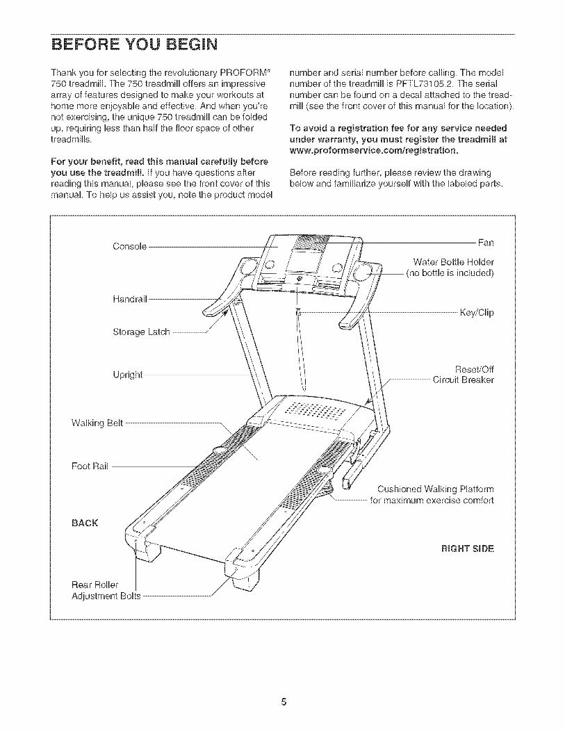
Before reading further, please review the drawingbelow and familiarize yourself with the labeled parts,
Console
Handrail
Storage Latch
Fan
Water Bottle Holder(no bottle is included)
Key/Clip
UprightReset/Off
Circuit Breaker
Walking Belt
Foot Rail
BACK
Cushioned Walking Platformfor maximum exercise comfort
RIGHT SIDE
Rear Roller
To hire an authorized service technician to assemble the trearfmilt, call totJ-free 1-800-445-2480.
Assembty requires two persons. Set the treadmill in a cbared area and remove all packing materials, Do notdispose of the packing materials until assembly is compbted, Note: The underside of the treadmill walking belt iscoated with high-performance lubrbant, During shipping, a small amount of lubrbant may be transferred to thetop of the walking belt or the shipping carton, This is a normal condition and does not affect treadmill perfor-mance, If there is lubricant on top of the walking belt, simply wipe off the lubricant with a soft cloth and a mild,non-abrasive cleaner,
Assembty requires the included allen wrench _ and your own philtips screwdriver (witha shaft at teast 8" tong) and wire cutters _:_o_ .
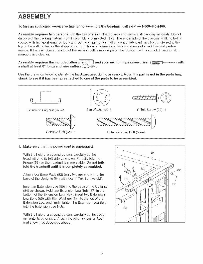
Use the drawings below to identify the hardware used during assembly, Note: if a part is not in the parts bag,check to see if it has been preattached to one of the parts to be assemblerf.
Extension Leg Nut (67)-4
@Star Washer (8)-8 1" Tek Screw (22)-4
Console Bolt (64)-4 Extension Leg Bolt (65)-4
1, Make sure that the power cord is unpluggerf.
With the help of a second person, carefully tip thetreadmill onto its left side as shown, Partially fold theFrame (58) so the treadmill is more stable, Do not fullyfold the treadmill until it is completely assemMed.
Attach four Base Pads (82) (only two are shown) to thebase of the Uprights (84) with four 1" Tek Screws (22),
insert an Extension Leg (89) into the base of the Uprights(84) as shown, Hold two Extension Leg Nuts (67) in thebottom of the Extension Leg, Next, insert two ExtensionLeg Bolts (65) with Star Washers (8) into the top of theExtension Leg, and firmly tighten the Extension Leg Boltsinto the Extension Leg Nuts,
With the help of a second person, carefully tip the tread-mill onto its other side, Attach the other Extension Leg(not shown) as described above,
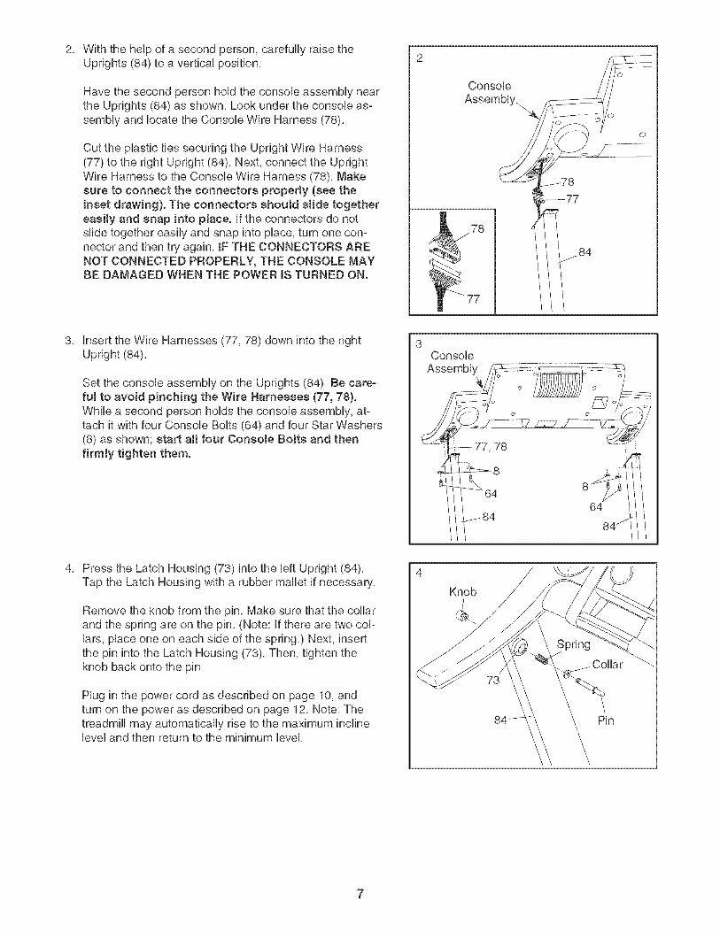
CuttheplastictiessecuringtheUprightWireHarness(77)totherightUpright(84),Next,connecttheUprightWireHarnesstotheConsoleWireHarness(78),Makesureto connecttheconnectorsproperly(seetheinsetdrawing).TheconnectorsshouldsJidetogethereasily and snap into pJace, if the connectors do notslide together easily and snap into place, turn one con-nector and then try again, iF THE CONNECTORS ARENOT CONNECTED PROPERLY, THE CONSOLE MAYBE DAMAGED WHEN THE POWER mSTURNED ON.
Console
Assembly.
._78
77
insert the Wire Harnesses (77, 78) down into the rightUpright (84),
Set the console assembly on the Uprights (84), Be care-fui to avoid pinching the Wire Harnesses (77, 78).While a second person holds the console assembly, at-tach it with four Console Bolts (64) and four Star Washers(8) as shown; start aH four Console BoJts and thenfirmly tighten them.
ConsoleAssembly
64
84j
Press the Latch Housing (73) into the left Upright (84),Tap the Latch Housing with a rubber mallet if necessary,
Remove the knob from the pin, Make sure that the collarand the spring are on the pin, (Note: if there are two col-lars, place one on each side of the spring,) Next, insertthe pin into the Latch Housing (73), Then, tighten theknob back onto the pin,
Hug in the power cord as described on page 10, andturn on the power as described on page 12, Note: Thetreadmill may automatically rise to the maximum inclinelevel and then return to the minimum level,
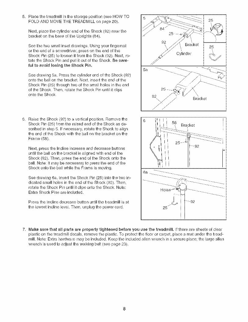
Seethetwosmallinsetdrawings,Usingyourfingernailortheendofascrewdriver,pressontheendoftheShockPin(25)to loosenitfromtheShock(92),Next,to°tatetheShockPinandpullitoutoftheShock,Becare-ful to avoidtosingtheShockPin.
Raise the Shock (92) to a vertical position, Remove theShock Pin (25) from the raised end of the Shock as de-scribed in step 5, if necessary, rotate the Shock to alignthe end of the Shock with the ball on the bracket on theFrame (58),
Next, press the Incline increase and decrease buttonsuntil the ball on the bracket is aligned with end of theShock (92), Then, press the end of the Shock onto theball, Note: it may be necessary to press the end of theShock onto the ball while the Frame is moving,
See drawing 6a, insert the Shock Pin (25) into the two in-dicated small hobs in the end of the Shock (92), Then,rotate the Shock Pin until it clips onto the Shock, Note:Extra Shock Pins are included,
Press the Incline decrease button until the treadmill is at
the lowest incline level, Then, unplug the power cord,
6a
Bracket
/
7, Make sure that aH parts are properly tightened before you use the treadmill, if there are sheets of clearplastic on the treadmill decals, remove the plastic, To protect the floor or carpet, place a mat under the tread°mill, Note: Extra hardware may be included, Keep the included allen wrench in a secure place; the large allenwrench is used to adjust the walking belt (see page 23),
8
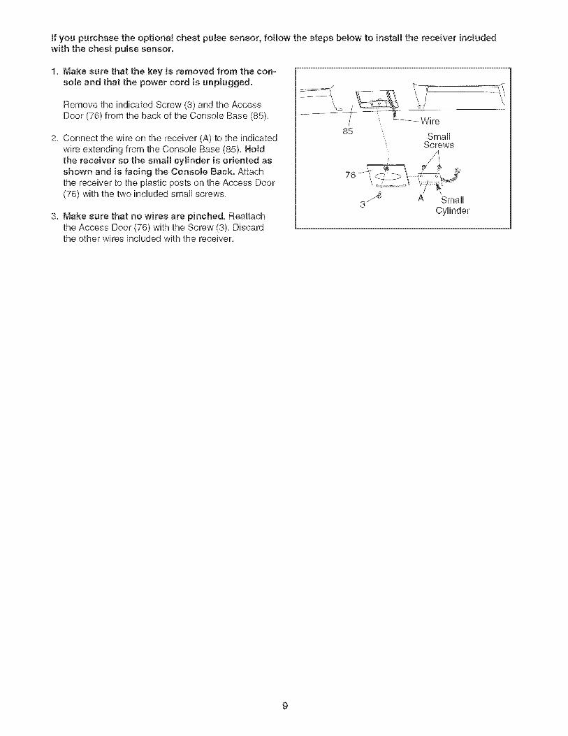
if you purchase the optional chest pulse sensor, follow the steps below to install the receiver includedwith the chest pulse sensor.
1, Make sure that the key is removed from the con-sole and that the power cord is unplugged.
Remove the indicated Screw (3) and the AccessDoor (76) from the back of the Console Base (85),
2, Connect the wire on the receiver (A) to the indicatedwire extending from the ConsoUe Base (85), HoJdthe receiver so the small cylinder is oriented asshown and is facing the Console Back. Attachthe receiver to the pUastb posts on the Access Door(76) with the two included small screws,
3, Make sure that no wires are pinched. Reattachthe Access Door (76) with the Screw (3), Discardthe other wires included with the receiver,
,, Small", Screws
3 _ A SmallCylinder
OPERATmON AND ADJUSTMENT
THE PRE-LUBRICATED WALKING BELT
Your treadmHUfeatures a waUking beUtcoated with high°performance Uubrbant, IMPORTANT: Never apply sil-icone spray or other substances to the waJkingbeJt or the walking platform. Such substances willdeteriorate the walking belt and cause excessivewear.
HOW TO PLUG IN THE POWER CORD
DANG ER: Improperconnectionof the equipment-grounding conductor canresuJt in an increased risk of eJectric shock.
Check with a qualified eJectrician or service-man if you are in doubt as to whether theproduct is properly grounded. Do not modifythe plug provided with the productJif it wHJnot fit the outlet, have a proper ouUetinstalled by a quaJified eJectrician.
Your treadmill, like any other type of sophisticatedelectronic equipment, can be seriously damaged bysudden voltage changes in your home's power,Voltage surges, spikes, and noise interference canresult from weather conditions or from other appliancesbeing turned on or off, To decrease the possibility ofyour treadmill being damaged, always use a surgesuppressor with your treadmill (see drawing 1 atthe right}. To purchase a surge suppressor, seeyour JocaJ PROFORM deaJer or call the toll-freeteJephone number on the front cover of this man-ual and order part number 146148, or see your JocaJelectronics store.
Use onJy a single-outlet surge suppressor that isUL 1449 Jisted as a transient voltage surge sup-pressor (TVSS}. The surge suppressor must have aUL suppressed vottage rating of 400 volts or tessand a minimum surge dissipation of 450 joules.The surge suppressor must be electrically rated for120 volts AC and 15 amps. There must be a moni-toring Hght on the surge suppressor to indicatewhether it is functioning properly. Failure to use aproperJy functioning surge suppressor could resuJtin damage to the controt system of the treadmill. Ifthe control system is damaged, the waJking beltmay change speed, accelerate or stop unexpect-edly, which may result in a fail and serious injury.
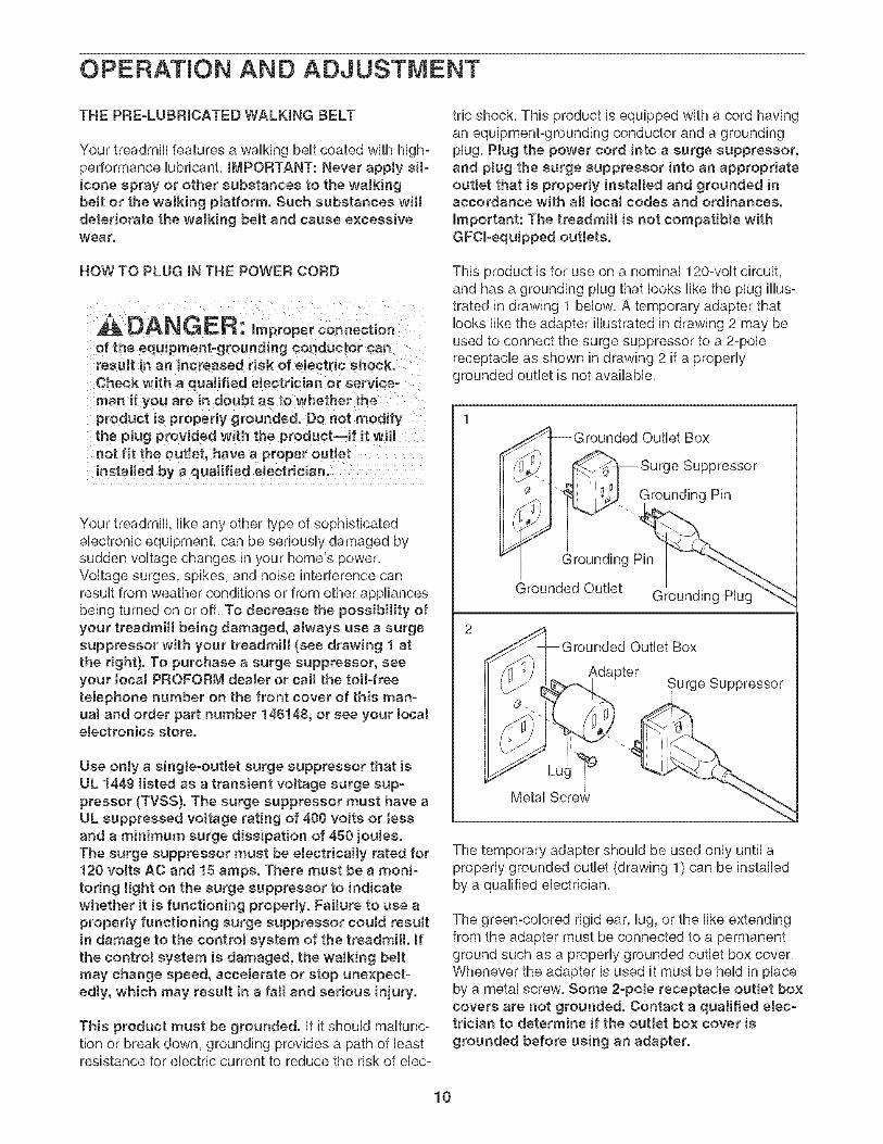
This product must be grounded, if it should maifunc°tion or break down, grounding provides a path of leastresistance for electric current to reduce the risk of ebc°
tric shock. This product is equipped with a cord havingan equipment-grounding conductor and a groundingplug, Plug the power cord into a surge suppressor,and pJug the surge suppressor into an appropriateoutlet that is properly installed and grounded inaccordance with aH JocaJ codes and ordinances.
Important: The treadmill is not compatible withGFOl-equipped outJets.
This product is for use on a nominal 120-volt circuit,and has a grounding plug that looks like the plug illus-trated in drawing 1 below, A temporary adapter thatlooks like the adapter illustrated in drawing 2 may beused to connect the surge suppressor to a 2-polereceptacle as shown in drawing 2 if a properlygrounded outlet is not available,
I-Grounded Outlet Box
¢-1 _ 9urge Suppressor
_ ['_ IS_. Grounding Pin
_rounded Outlet Grounding Plug"_
2_rounded Outlet Box
AdapterSurge Suppressor
The temporary adapter should be used only until aproperly grounded outlet (drawing 1) can be installedby a qualified electrician,
The green-colored rigid ear, lug, or the like extendingfrom the adapter must be connected to a permanentground such as a properly grounded outlet box cover,Whenever the adapter is used it must be held in placeby a metal screw, Some 2-poJe receptacle outJet boxcovers are not grounded. Contact a qualified elec-trician to determine if the outlet box cover is
grounded before using an adapter.
10
PERSONALTRAINER
PROGRAMS
Matrix
I
7Pri°ritylDisplay _/
.....WSS0' '-I
..... B&,,olD sp ay
9 _ PULSE
STOP
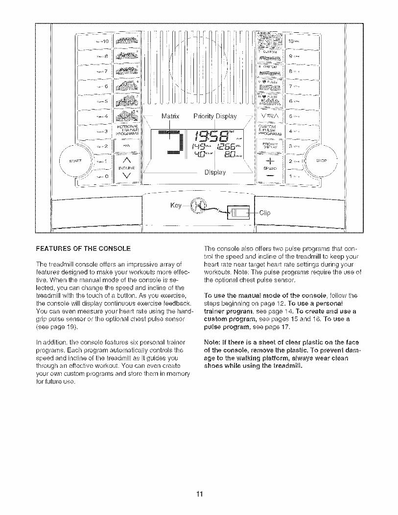
FEATURES OF THE CONSOLE
The treadmill console offers an impressive array offeatures designed to make your workouts more effec-tive, When the manual mode of the console is se-
lected, you can change the speed and incline of thetreadmill with the touch of a button, As you exercise,the console will display continuous exercise feedback,You can even measure your heart rate using the hand-grip pulse sensor or the optional chest pulse sensor(see page 19),
in addition, the console features six personal trainerprograms, Each program automatically controls thespeed and incline of the treadmill as it guides youthrough an effective workout, You can even createyour own custom programs and store them in memoryfor future use,
The console also offers two pulse programs that con-trol the speed and incline of the treadmill to keep yourheart rate near target heart rate settings during yourworkouts, Note: The pulse programs require the use ofthe optional chest pulse sensor,
To use the manuaJ mode of the consob, follow thesteps beginning on page 12, To use a personaltrainer program, see page 14, To create and use acustom program, see pages 15 and 16, To use apulse program, see page 17,
Note: If there is a sheet of clear plastic on the faceof the console, remove the plastic. To prevent dam-age to the walking platform, always wear cleanshoes while using the treadmill.
11
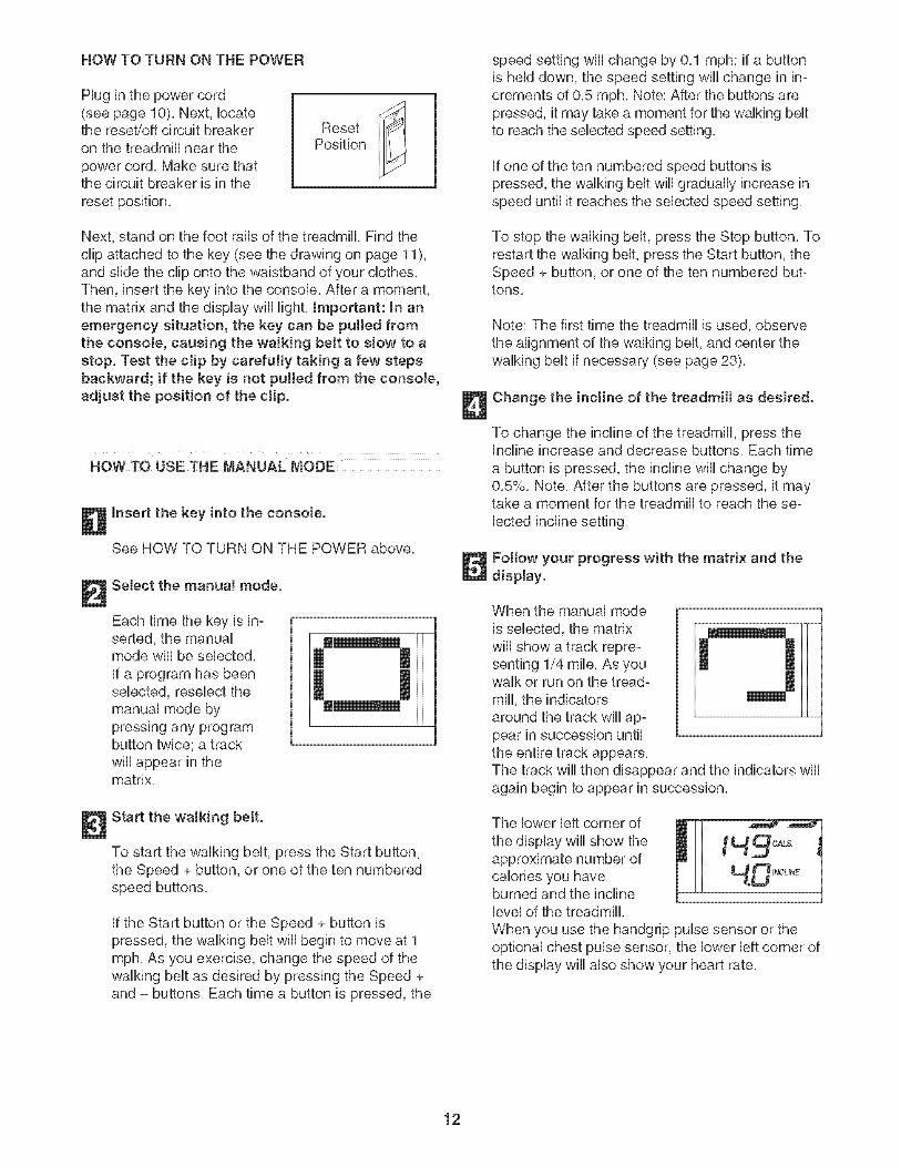
HOW TO TURN ON THE POWER
Hug in the power cord(see page 10), Next, locatethe reset/off circuit breakeron the treadmill near the
power cord, Make sure thatthe circuit breaker is in thereset position,
ResetPosition
Next, stand on the foot rails of the treadmill, Find theclip attached to the key (see the drawing on page 11),and slide the clip onto the waistband of your clothes,Then, insert the key into the console, After a moment,the matrix and the display wiii light, Important: In anemergency situation, the key can be pulled fromthe consoJe, causing the walking belt to sJow to astop. Test the clip by carefully taking a few stepsbackward; if the key is not pulled from the consoJe,adjust the position of the clip.
NOW TO USE THE MANUAL MODE
Insert the key into the console.
See HOW TO TURN ON THE POWER above,
Select the manuaJ mode.
Each time the key is in-serted, the manualmode wiii be selected,if a program has beenselected, reselec_tthemanual mode bypressing any programbutton twice; a trackwiii appear in thematrix,
0 .1
Start the waJking belt.
To start the walking belt, press the Start button,the Speed + button, or one of the ten numberedspeed buttons,
if the Start button or the Speed + button ispressed, the walking belt wiii begin to move at 1mph, As you exercise, change the speed of thewalking belt as desired by pressing the Speed +and - buttons, Each time a button is pressed, the
speed setting wiii change by 0,1 mph; if a buttonis held down, the speed setting will change in in-crements of 0,5 mph, Note: After the buttons arepressed, it may take a moment for the walking beltto reach the selected speed setting,
if one of the ten numbered speed buttons ispressed, the walking belt wiii gradually increase inspeed until it reaches the selected speed setting,
To stop the walking belt, press the Stop button, Torestart the walking belt, press the Start button, theSpeed + button, or one of the ten numbered but-tons,
Note: The first time the treadmill is used, observethe alignment of the walking belt, and center thewalking belt if necessary (see page 23),
Change the incline of the treadmill as desired.
To change the incline of the treadmill, press theIncline increase and decrease buttons, Each time
a button is pressed, the incline wiii change by0,5%, Note: After the buttons are pressed, it maytake a moment for the treadmill to reach the se-
lected incline setting,
Follow your progress with the matrix and thedisplay.
When the manual modeis selected, the matrixwiii show a track repre-senting 1/4 mile, As youwalk or run on the tread°mill, the indicatorsaround the track wiii ap-pear in succession untilthe entire track appears,
[] []
The track wiii then disappear and the indicators wiiiagain begin to appear in succession,
The lower left corner of
the display wiii show the
calories you haveburned and the inclinelevel of the treadmill,
HoD JNcuNE
When you use the handgrip pulse sensor or theoptional chest pulse sensor, the lower left corner ofthe display wiii also show your heart rate,
12
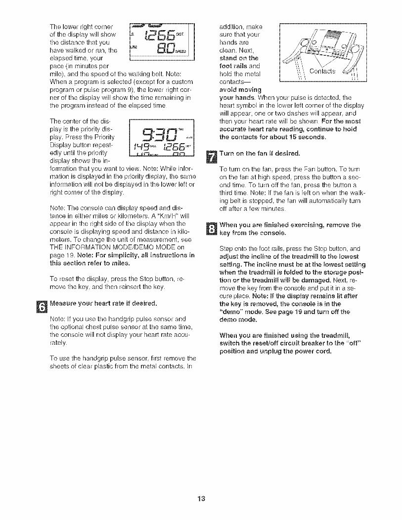
The lower right corner I _'r'_r
of the display wiii show }-s- _,_ CCD_sT.the distance that you _NE _Jt_have walked or run, the QoUSPEEDelapsed time, yourpace (in minutes permile), and the speed of the walking belt. Note:When a program is selected (except for a customprogram or pulse program 9), the lower right cor-ner of the display will show the time remaining inthe program instead of the elapsed time.
The center of the dis-
play is the priority dis-play. Press the PriorityDisplay button repeat°edly until the prioritydisplay shows the in-formation that you want to view. Note: While infor-mation is displayed in the priority display, the sameinformation wiii not be displayed in the lower left or
Note: The console can display speed and dis-tance in either miles or kilometers. A "Km/H" will
appear in the right side of the display when theconsole is displaying speed and distance in kilo-meters. To change the unit of measurement, seeTHE iNFORMATiON MODE/DEMO MODE onpage 19. Note: For simplicity, aH instructions inthis section refer to miles.
To reset the display, press the Stop button, re-move the key, and then reinsert the key.
Measure your heart rate if desired.
Note: if you use the handgrip pulse sensor andthe optional chest pulse sensor at the same time,the console will not display your heart rate accu-rately.
To use the handgrip pulse sensor, first remove thesheets of clear plastic from the metal contacts, in
addition, makesure that yourhands areclean. Next,stand on thefoot rails andhold the metal Contactscontacts--
avoid movingyour hands. When your pulse is detected, theheart symbol in the lower left corner of the displaywill appear, one or two dashes will appear, andthen your heart rate will be shown. For the mostaccurate heart rate reading, continue to hoMthe contacts for about 15 seconds.
Turn on the fan if desired.
To turn on the fan, press the Fan button. To turnon the fan at high speed, press the button a sec-ond time. To turn off the fan, press the button athird time. Note: if the fan is left on when the walk-
ing belt is stopped, the fan will automatically turnoff after a few minutes.
When you are finished exercising, remove thekey from the console.
Step onto the foot rails, press the Stop button, andadjust the incline of the treadmill to the lowestsetting. The incline must be at the lowest settingwhen the treadmill is fotded to the storage posi-tion or the treadmill will be damaged. Next, re-move the key from the console and put it in a se-cure place. Note: If the display remains tit afterthe key is removed, the consoJe is in the"demo" mode. See page 19 and turn off thedemo mode.
When you are finished using the treadmill,switch the reset/off circuit breaker to the "off"
position and unptug the power cord.
13
HOW TO USE A PERSONAL TRAINER PROGRAM
mnsert the key into the console.
See HOW TO TURN ON THE POWER on page12.
Select one of the personal trainer programs.
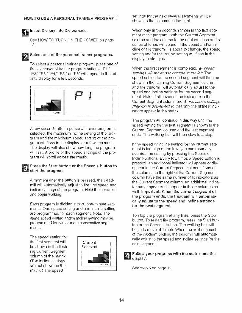
To select a personal trainer program, press one ofthe six personal trainer program buttons; "P1 ,""P2," "P3," "P4," "P5," or "P6" will appear in the pri-ority display for a few seconds.
A few seconds after a personal trainer program usselected, the maximum incline setting of the pro-gram and the maximum speed setting of the pro-gram will flash in the display for a few seconds.The display will also show how long the programwill last. A profile of the speed settings of the pro-gram will scroll across the matrix.
Press the Start button or the Speed + button tostart the program.
A moment after the button is pressed, the tread-mill will automatically adjust to the first speed andincline settings of the program. Hold the handrailsand begin walking.
Each program is divided into 30 one-minute seg-ments. One speed setting and one incline settingare programmed for each segment. Note: Thesame speed setting and/or incline setting may beprogrammed for two or more consecutive seg-ments.
The speed setting forthe first segment wiiibe shown in the flash-
ing Current Segmentcolumn of the matrix,
(The incline settingsare not shown in the
matrix,) The speed
Current
Segment
PROGRAM
settings for the next several segments wiii beshown in the columns to the right,
When only three seconds remain in the first seg-ment of the program, both the Current Segmentcolumn and the column to the right will flash and aseries of tones will sound, if the speed and/or in-cline of the treadmill is about to change, the speedsetting and/or the incline setting wiii flash in thedisplay to alert you,
When the first segment is completed, allepeedee4@7_5"v/i//move one coidmn to the ie,_t.Thespeed setting for the second segment will then beshown in the flashing Current Segment column,and the treadmill will automatically adjust to thespeed and incline settings for the second seg-ment. Note: if all seven of the indicators in the
Current Segment column are lit, the ei2eed'ee4dp_:¢maymove downv/afdso that only the highest indi-cators appear in the matrix.
The program will continue in this way until thespeed setting for the last segment is shown in theCurrent Segment column and the last segmentends, The walking belt wiii then slow to a stop,
if the speed or incline setting for the current seg-ment is too high or too low, you can manuallyoverride the setting by pressing the Speed orIncline buttons, Every few times a Speed button ispressed, an additional indicator wiii appear or dis-appear in the Current Segment column; if any ofthe columns to the right of the Current Segmentcolumn have the same number of lit indicators as
the Current Segment column, an additional indica-tor may appear or disappear in those columns aswell, Important: When the current segment ofthe program ends, the treadmill will automati-cally adjust to the speed and incline settingsfor the next segment.
To stop the program at any time, press the Stopbutton. To restart the program, press the Start but-ton or the Speed + button. The walking belt willbegin to move at 1 mph. When the next segmentof the program begins, the treadmill will automati-cally adjust to the speed and incline settings for thenext segment.
Follow your progress with the matrix and thedisplay.
See step 5 on page 12.
14
Measure your heart rate if desired.
See step 6 on page 13,
Turn on the fan if desired.
See step 7 on page 13,
When you are finished exercising, remove thekey from the consote.
When the program ends, make sure that the in-cline of the treadmil! is at the towest setting.Next, remove the key from the consob and put it ina safe pUace,Note: If the display remains litafter the key is removed, the console is in the"demo" mode. See page 19 and turn off thedemo mode.
When you are finished using the treadmill,switch the reset/off circuit breaker to the "off"
position and unplug the power cord.
NOW TO CREATE A CUSTOM PROGRAM
Insert the key into the consote.
See HOW TO TURN ON THE POWER on page12,
Select one of the custom programs.
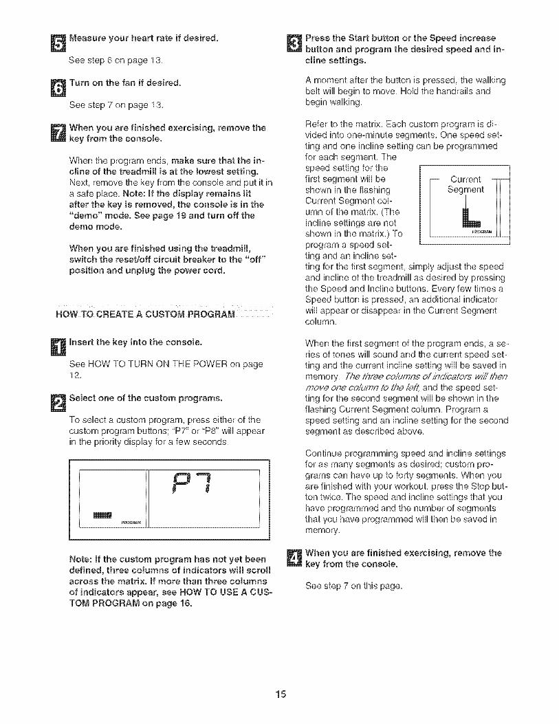
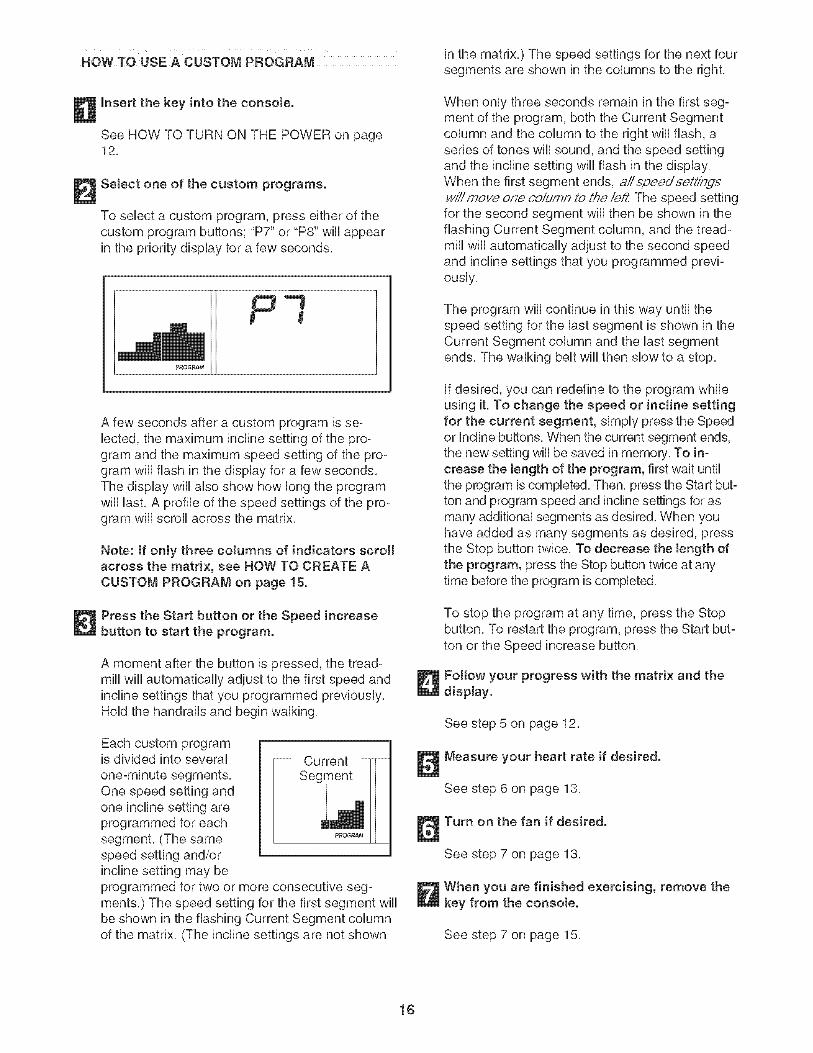
To sebct a custom program, press either of thecustom program buttons; "P7" or "P8" wHUappearin the priority display for a few seconds,
mmPROG_M
Note: If the custom program has not yet beendefined, three cotumns of indicators will scrollacross the matrix. If more than three columnsof indicators appear, see NOW TO USE A CUS-TOM PROGRAM on page 16.
Press the Start button or the Speed increasebutton and program the desired speed and in-cline settings.
A moment after the button is pressed, the walkingbelt will begin to move, Hold the handrails andbegin walking,
Refer to the matrix, Each custom program is di-vided into one-minute segments, One speed set-ting and one incline setting can be programmedfor each segment, Thespeed setting for thefirst segment wiii beshown in the flashingCurrent Segment copumn of the matrix, (Theincline settings are notshown in the matrix,) Toprogram a speed set-ting and an incline set-
- Current -_
Segment
PROGRAtvI
ting for the first segment, simply adjust the speedand incline of the treadmill as desired by pressingthe Speed and incline buttons, Every few times aSpeed button is pressed, an additional indicatorwill appear or disappear in the Current Segmentcolumn,
When the first segment of the program ends, a se-ries of tones wiii sound and the current speed set-ting and the current incline setting will be saved inmemory, The three co/umne of/ho'/catore wi// thenmove one co/umn to the/e/,,_ and the speed set-ting for the second segment will be shown in theflashing Current Segment column, Program aspeed setting and an incline setting for the secondsegment as described above,
Continue programming speed and incline settingsfor as many segments as desired; custom pro°grams can have up to forty segments, When youare finished with your workout, press the Stop but-ton twice, The speed and incline settings that youhave programmed and the number of segmentsthat you have programmed wiii then be saved inmemory,
When you are finished exercising, remove thekey from the consote.
See step 7 on this page,
15
HOW TO USE A CUSTOM PROGRAM
mnsert the key into the console.
See HOW TO TURN ON THE POWER on page12,
Select one of the custom programs.
To select a custom program, press either of thecustom program buttons; "P7" or "P8" wHiappearin the priority dispiay for a few seconds,
A few seconds after a custom program is se-lected, the maximumgram and the maximum speed setting of the pro-gram wHi flash in the dispiay for a few seconds,The dispiay wHi aiso show how Hungthe programwHiHast,A profile of the speed settings of the pro-gram wHi scroli across the matrix,
Note: If only three columns of indicators scrollacross the matrix, see HOW TO CREATE ACUSTOM PROGRAM on page 15.
Press the Start button or the Speed increasebutton to start the program.
A moment after the button is pressed, the tread-mill will automatically adjust to the first speed andincline settings that you programmed previously,Hold the handrails and begin walking,
Each custom programis divided into several
One speed setting andoneprogrammed for eachsegment, (The samespeed setting and/orincline setting may beprogrammed for two or more consecutive seg-ments.) The speed setting for the first segment wiiibe shown in the flashing Current Segment columnof the matrix. (The incline settings are not shown
in the matrix,) The speed settings for the next foursegments are shown in the columns to the right,
When only three seconds remain in the first seg-ment of the program, both the Current Segmentcolumn and the column to the right will flash, aseries of tones will sound, and the speed settingand the incline setting wiii flash in the display.When the first segment ends, aiispe.e.d'seLff/7dswiii mo_'e,one co/dmn to tA_e/eft, The speed settingfor the second segment will then be shown in theflashing Current Segment column, and the tread-mill will automatically adjust to the second speedand incline settings that you programmed previ-ously,
The program will continue in this way until thespeed setting for the last segment is shown in theCurrent Segment column and the last segmentends. The walking belt wiii then slow to a stop.
if desired, you can redefine to the program whileusing it, To change the speed or incline settingfor the current segment, simply press the Speedor Incline buttons, When the current segment ends,the new setting will be saved in memory, To in-crease the length of the program, first wait untilthe program is completed, Then, press the Start but-ton and program speed and incline settings for asmany additional segments as desired, When youhave added as many segments as desired, pressthe Stop button twice, To decrease the Jength ofthe program, press the Stop button twice at anytime before the program is completed,
To stop the program at any time, press the Stopbutton, To restart the program, press the Start but-ton or the Speed increase button,
Fottow your progress with the matrix and thedisplay.
See step 5 on page 12,
Measure your heart rate if desired.
See step 6 on page 13,
Turn on the fan if desired.
See step 7 on page 13,
When you are finished exercising, remove thekey from the consote.
See step 7 on page 15,
16
HOWT0 USE A PULSE PROGRAM
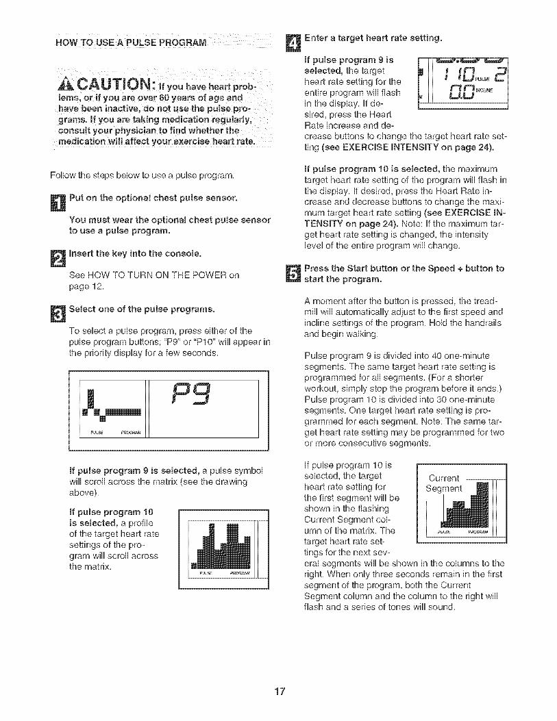
CA UTIO N: ifyouhoveheartprob-lems,or if you are over 60 years of age andhave been hsactive, do not use the pulse pro-grams, mfyou are taking medication regularly,consult your physician to find whether themedication will affect your exercise heart rate.
Follow the steps bebw to use a pube program,
Put on the optional chest putse sensor.
You must wear the optional chest pulse sensorto use a pulse program.
Insert the key into the consote.
See HOW TO TURN ON THE POWER onpage 12,
Select one of the putse programs.
To sebct a pube program, press either of thepuUseprogram buttons; "P9" or "PIO" wHUappear inthe priority display for a few seconds,
If pulse program g is selected, a pulse symbolwii[ scroll across the matrix (see the drawingabove),
If puJse program !0is seJected, a profileof the target heart ratesettings of the pro-gram will scroll acrossthe matrix,
Enter a target heart rate setting.
If puJse program 9 isselected, the targetheart rate setting for theentire program will flashin the display, If de-sired, press the HeartRate increase and de-crease buttons to change the target heart rate set-ting (see EXERCISE INTENSITY on page 24}.
if pulse program 10 is selected, the maximumtarget heart rate setting of the program will flash inthe display, If desired, press the Heart Rate in-crease and decrease buttons to change the maxi-mum target heart rate setting (see EXERCISE IN-TENSITY on page 24}. Note: If the maximum tar-get heart rate setting is changed, the intensitylevel of the entire program will change,
Press the Start button or the Speed + button tostart the program.
A moment after the button is pressed, the tread-mill will automatically adjust to the first speed andincline settings of the program, Held the handrailsand begin walking,
Pulse program 9 is divided into 40 one-minutesegments, The same target heart rate setting isprogrammed for all segments, (For a shorterworkout, simply stop the program before it ends,)Pulse program 10 is divided into 30 one-minutesegments, One target heart rate setting is pro-grammed for each segment, Note: The same tar-get heart rate setting may be programmed for twoor more consecutive segments,
If pulse program 10 isselected, the targetheart rate setting forthe first segment will beshown in the flashingCurrent Segment col-umn of the matrix, The
target heart rate set-tings for the next sev-
Current --
SegmentPULSE PROGR&M
eral segments wiii be shown in the columns to theright, When only three seconds remain in the firstsegment of the program, both the CurrentSegment column and the column to the right willflash and a series of tones will sound,
17
When the first segment ends, allta,%etheaftrateset,@gs wiiimove one coiumn /othe/eft.The tar=get heart rate setting for the second segment wHUthen be shown in the flashing Current SegmentcoUumn,
During both pulse programs, the console wiii reg°ularly compare your heart rate to the target heartrate setting, if your heart rate is too far below orabove the target heart rate setting for the currentsegment, the speed of the walking belt will auto°matically increase or decrease to bring your heartrate closer to the target heart rate setting,
if the speed or incline setting is too high or too lowat any time during the program, you can adjust thesetting with the Speed or Incline buttons, However,when the console compares your heart rate to thetarget heart rate setting, the speed of the treadmillmay automatically change to bring your heart ratecloser to the target heart rate setting,
if your pulse is not detected during the program,the letters "PLS" wiii flash in the display and thespeed of the treadmill may automaticallydecrease, if this occurs, see the instructions in-cluded with the optional chest pulse sensor,
To stop the program at any time, press the Stopbutton, To restart the program, press the Start but-ton or the Speed + button, The walking belt willbegin to move at 1 mph, When the console com-pares your heart rate to the target heart rate set-ting, the speed and/or incline of the treadmill mayautomatically change to bring your heart ratecloser to the target heart rate setting,
Follow your progress with the matrix and thedisplay.
See step 5 on page 12,
Turn on the fan if desired.
See step 7 on page 13,
When you are finished exercising, remove thekey from the console.
See step 7 on page 15,
18
THE mNFORMATmONMODE/DEMO MODE
The consob features an information mode that keepstrack of the totaUnumber of hours that the treadmHUhasbeen operated and the totaUdistance that the waUkingbeUthas moved. The information mode aUsoallows youto sebct miles or kilometers as the unit of measure-ment and to turn on and turn off the demo mode.
To sebct the information mode, hoUddown the Stopbutton while inserting the key into the consob, andthen rebase the Stop button. When the informationmode is sebcted, the following information wHUbe dis-pUayed:
pUaywHUshow thetotaUnumber of
miles (or kilome-ters) that thewalking belt hasmoved. Thelower right cornerof the display will
Ce C
show the total number of hours that the treadmill hasbeen operated. An "E" for English miles or an "M" formetric kilometers will appear in the lower left corner ofthe display. Press the Speed + button to change theunit of measurement if desired.
IMPORTANT: If a"d" appears in thelower left corner
of the display, theconsole is in the"demo" mode.This mode is in-tended to be used
only when a
d ;2'4t"" t"lt P_
treadmill is displayed in a store. When the console is inthe demo mode, the power cord can be plugged in, thekey can be removed from the console, and the indica-tors in the display will automatically appear in a presetsequence; the buttons on the console will not operate. Ifa "d" appears when the information mode is se-lected, press the Speed - button so "d" disappears.
To exit the information mode, remove the key from theconsole.
THE OPTIONAL CHESTPULSESENSOR
The optional chest pulse sensor offers hands-free op-eration and enables you to use the console's pulseprograms. To purchase the optionaJ chest puJsesensor, call the toll-free telephone number on thefront cover of this manual
19
HOW TO FOLD AND MOVE THE TREADMILL
HOW TO FOLD THE TREADMmLL FOR STORAGE
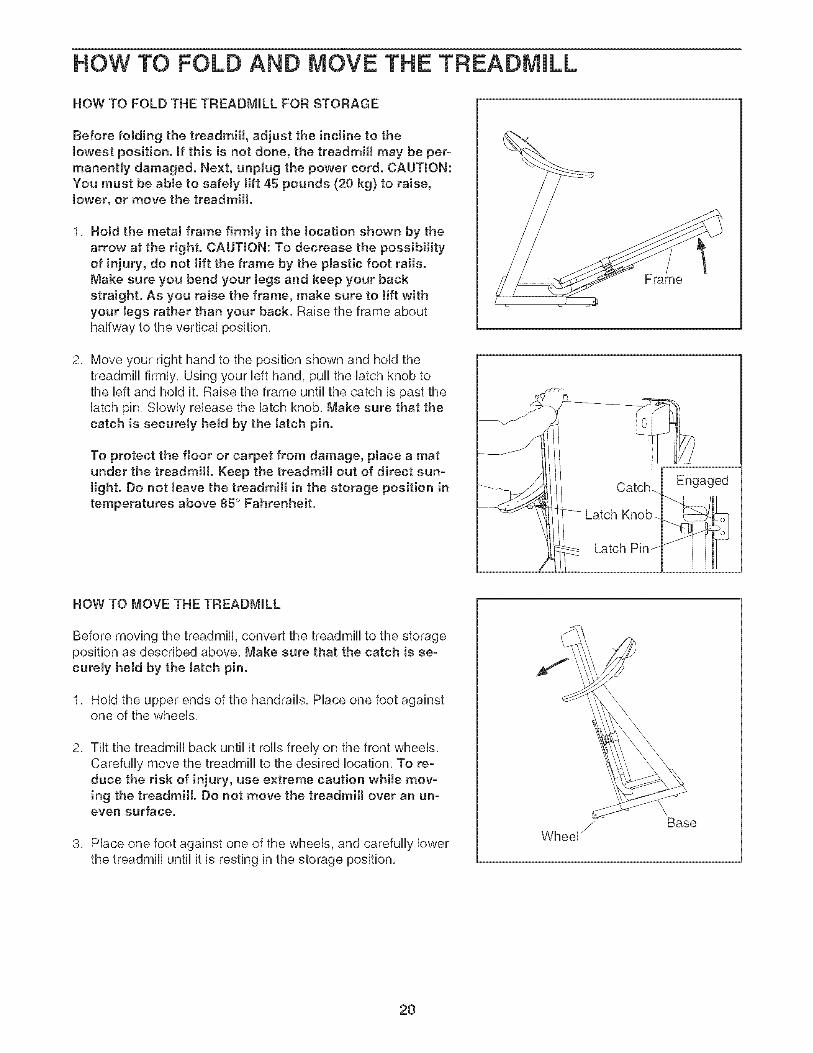
Before folding the treadmill, adjust the incline to thelowest position, mftMs is not done, the treadmill may be per-manently damaged. Next, unplug the power cord. CAUTmON:You must be able to safely lift 45 pounds (20 kg) to raise,tower, or move the treadmill.
1, Hold the metal frame firmly in the location shown by thearrow at the right. CAUTmON: To decrease the possibilityof injury, do not lift the frame by the plastic foot raits.Make sure you bend your Jegs and keep your backstraight. As you raise the frame, make sure to Hft withyour Jegs rather than your back. Raise the frame abouthalfway to the vertical position,
2, Move your right hand to the position shown and hold thetreadmill firmly, Using your left hand, pull the latch knob tothe left and hold it, Raise the frame until the catch is past thelatch pin, Slowly release the latch knob, Make sure that thecatch is securely held by the tatch pin,
To protect the floor or carpet from damage, place a matunder the treadmill. Keep the treadmill out of direct sun-tight. Do not leave the treadmill in the storage position intemperatures above 85 ° Fahrenheit.
Frame
HOW TO MOVE THE TREADMILL
Before moving the treadmill, convert the treadmill to the storageposition as described above, Make sure that the catch is se-curely held by the tatch pin.
1, Hold the upper ends of the handrails, Place one foot againstone of the wheels,
2, Tilt the treadmill back until it rolls freely on the front wheels,Carefully move the treadmill to the desired location, To re-duce the risk of injury, use extreme caution while mov-ing the treadmill. Do not move the treadmill over an un-even surface.
3, Place one foot against one of the wheels, and carefully lowerthe treadmill until it is resting in the storage position,
Base
2O
HOW TO LOWER THE TREADMmLL FOR USE
1, HoUdthe upper end of the treadmHUwith your right hand, Pullthe Uatchknob to the Ueftand hoUdit, Pivot the treadmHUdownuntil the catch is past the Uatchpin,
2, HoJd the metal frame firmly with both hands, and UowerthetreadmHUto the floor, CAUTION: To decrease the possibilityof injury, do not lower the treadmill by gdpping only theplastic foot rails. Do not drop the treadmill frame to thefloor. Be sure to bend your legs and keep your backstraight.
Frame
21
TROUBLESHOOTmNG
Most treadmill problems can be sotvod by following the steps below. Find the symptom that applies, andfottow the stops tistod, mffurther assistance is needed, please see the front covor of this manual.
PROBLEM: The power doos not turn on
SOLUTmON: a, Make sure that the power cord is plugged into a surge suppressor, and that the surge suppressoris plugged into a properly grounded outlet (see page 10). Use only a single-outlet surge suppres-sor that meets all of the specifications described on page 10. important: The treadmill is not com-patible with GFCI-equipped outlets.
b. After the power cord has been plugged in, make sure that the key is inserted into the console.
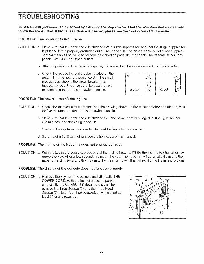
C, Check the reset/off circuit breaker located on the
treadmill frame near the power cord. if the switchprotrudes as shown, the circuit breaker hastripped. To reset the circuit breaker, wait for fiveminutes, and then press the switch back in. Tripped Reset
PROBLEM: The power turns off during use
SOLUTION: a. Check the reset/off circuit breaker (see the drawing above), if the circuit breaker has tripped, waitfor five minutes and then press the switch back in.
b. Make sure that the power cord is plugged in. if the power cord is plugged in, unplug it, wait forfive minutes, and then plug it back in.
c. Remove the key from the console. Reinsert the key into the console.
d. if the treadmill still will not run, see the front cover of this manual.
PROBLEM: The incline of the treadmill doos not chango correctly
SOLUTmON: a, With the key in the console, pross one of the Incline buttons, While the incline is changing, re-move the key. After a few seconds, re-insert the key. The treadmill will automatically rise to themaximum incline level and then return to the minimum level. This will recalibrate the incline system.
PROBLEM: The display of the consoto does not function property
SOLUTION: a, Remove the key from the console and UNPLUG THEPOWER CORD. With the help of a second person,carefully tip the Uprights (84) down as shown. Next,remove the three Screws (3) and the three HoodScrews (7)_ Note: A phillips screwdriver with a shaft atbast 5" long is required.
84
22
With the heUpof a second person, carefully raise theUprights (84) to the position shown, Carefully pivot theHood (41) off,
Locate the Reed Switch (63) and the Magnet (46) onthe left side of the Pulley (47), Turn the Pulley until theMagnet is aligned with the Reed Switch, Make surethat the gap between the Magnet and the ReedSwitch is about 1/8". if necessary, loosen the Screw(3), move the Reed Switch slightly, and then retightenthe Screw, Reattach the Hood, and run the treadmillfor a few minutes to check for a correct speed reading,
PROBLEM: The walking belt slows when walked on
Top @
@ I--
!I4SOLUTION: a, Use only a single-outlet surge suppressor that meets all of the specifications described on page 10,
b, if the walking belt is overtightened, treadmill perfor-mance may decrease and the walking belt may be-come damaged, Remove the key and UNPLUG THEPOWER CORD, Using the allen wrench, turn bothrear roller bolts counterclockwise, 1/4 of a turn, Whenthe walking belt is properly tightened, you should beable to lift each edge of the walking belt 2 to 3 inchesoff the walking platform, Be careful to keep the walk-ing belt centered, Then, plug in the power cord, insertthe key, and run the treadmill for a few minutes,Repeat until the walking belt is properly tightened,
Rear Roller Bolts
c, if the walking belt still slows when walked on, see the front cover of this manual,
PROBLEM: The waJking belt is off-center or stips when waJked on
SOLUTION: a, If the waIMng belt is off-center, first remove the keyand UNPLUG THE POWER CORD, mfthe walkingbelt has shifted to the left, use the allen wrench toturn the bft rear roller bolt clockwise 1/2 of a turn; ifthe walking belt has shifted to the right, turn theleft bolt counterclockwise 1/2 of a turn, Be careful not
to overtighten the walking belt, Then, plug in thepower cord, insert the key, and run the treadmill for afew minutes, Repeat until the walking belt is centered,
b, If the walking beJt slips when waJked on, first re-move the key and UNPLUG THE POWER CORD,Using the allen wrench, turn both rear roller boltsclockwise, 1/4 of a turn, When the walking belt is cor-rectly tightened, you should be able to lift each edgeof the walking belt 2 to 3 inches off the walking plat-form, Be careful to keep the walking belt centered,Then, plug in the power cord, insert the key, and care°fully walk on the treadmill for a few minutes, Repeatuntil the walking belt is properly tightened,
23
CONDiTiONiNG GUJDEUNES
WARNJNG: BeforebeginningtHsor any exercise program, consult your physi°cian. This is especially important for individu-als over the age of 35 or individuals with pre-existing health problems.
The pulse sensor is not a medical device.Various factors, including your movement,may affect the accuracy of heart rate readings.The sensor is intended onty as an exercise aidin determining heart rate trends in general
The following guidelines wiii help you to plan your ex=ercise program, For more detailed exercise informa=tion, obtain a reputable book or consult your physician,
EXERCISE iNTENSiTY
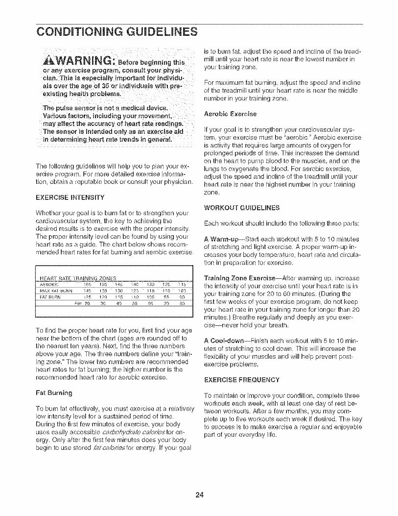
Whether your goal is to burn fat or to strengthen yourcardiovascular system, the key to achieving thedesired results is to exercise with the proper intensity,The proper intensity level can be found by using yourheart rate as a guide, The chart below shows recom-mended heart rates for fat burning and aerobic exercise,
HEART RATE TRAmNBNG ZONES
AEROBIC 165 155 t45 140 130 125 115
MAX FAT BURN 145 138 t30 125 118 110 103
FAT BURN 125 120 115 110 105 95 90
Age 20 30 40 50 60 70 80
To find the proper heart rate for you, first find your agenear the bottom of the chart (ages are rounded off tothe nearest ten years), Next, find the three numbersabove your age, The three numbers define your "train-ing zone," The lower two numbers are recommendedheart rates for fat burning; the higher number is therecommended heart rate for aerobic exercise,
Fat Burning
To burn fat effectively, you must exercise at a relativelylow intensity level for a sustained period of time,During the first few minutes of exercise, your bodyuses easily accessible carbohydrate caiorissfor en:ergy, Only after the first few minutes does your bodybegin to use stored fat ca/cries for energy, if your goal
is to burn fat, adjust the speed and incline of the tread-mill until your heart rate is near the lowest number inyour training zone,
For maximum fat burning, adjust the speed and inclineof the treadmill until your heart rate is near the middlenumber in your training zone,
Aerobic Exercise
if your goal is to strengthen your cardiovascular sys-tem, your exercise must be "aerobic," Aerobic exerciseis activity that requires large amounts of oxygen forprolonged periods of time, This increases the demandon the heart to pump blood to the muscles, and on thelungs to oxygenate the blood, For aerobic exercise,adjust the speed and incline of the treadmill until yourheart rate is near the highest number in your trainingzone,
WORKOUT GUIDELINES
Each workout should include the following three parts:
A Warm-up--Start each workout with 5 to 10 minutesof stretching and light exercise, A proper warm-up in-creases your body temperature, heart rate and circula-tion in preparation for exercise,
Training Zone Exercise--After warming up, increasethe intensity of your exercise until your heart rate is inyour training zone for 20 to 60 minutes, (During thefirst few weeks of your exercise program, do not keepyour heart rate in your training zone for longer than 20minutes,) Breathe regularly and deeply as you exer-cise-never hold your breath,
A CooFdown--Finish each workout with 5 to 10 min-
utes of stretching to cool down, This will increase theflexibility of your muscles and will help prevent post-exercise problems,
EXERCISE FREQUENCY
To maintain or improve your condition, complete threeworkouts each week, with at bast one day of rest be-tween workouts, After a few months, you may com-plete up to five workouts each week if desired, The keyto success is to make exercise a regular and enjoyablepart of your everyday life,
24
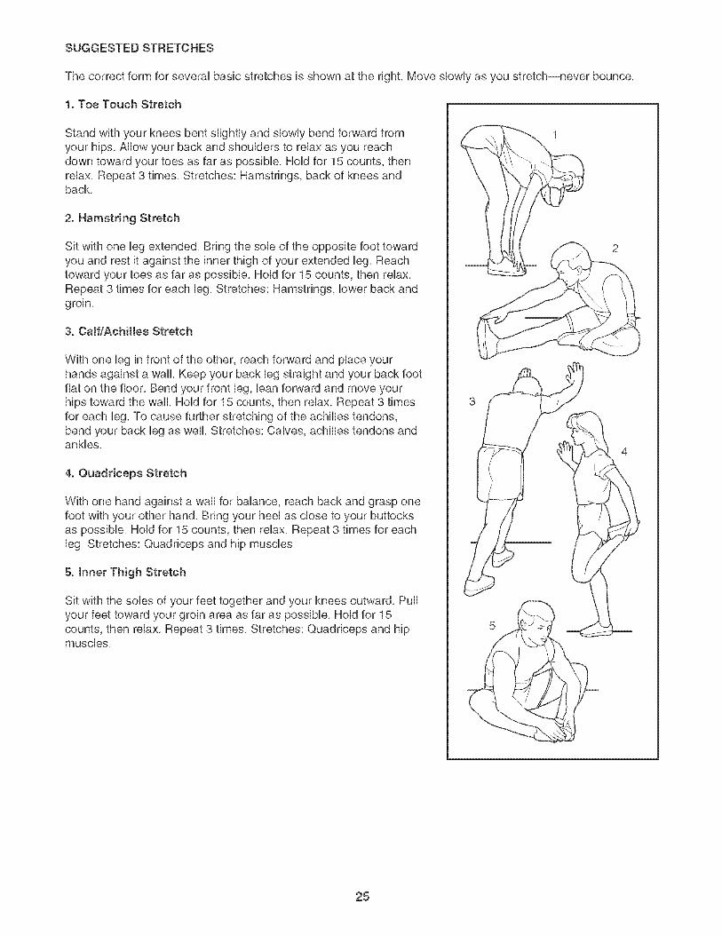
SUGGESTED STRETCHES
The correct form for several basic stretches is shown at the right, Move slowly as you stretch--never bounce,
1. Toe Touch Stretch
Stand with your knees bent slightly and slowly bend forward fromyour hips, Allow your back and shoulders to relax as you reachdown toward your toes as far as possible, Hold for 15 counts, thenrelax, Repeat 3 times, Stretches: Hamstrings, back of knees andback,
2. Hamstring Stretch
Sit with one leg extended, Bring the sob of the opposite foot towardyou and rest it against the inner thigh of your extended leg, Reachtoward your toes as far as possible, Hold for 15 counts, then relax,Repeat 3 times for each leg, Stretches: Hamstrings, lower back andgroin,
3. Caff/Achiltes Stretch
With one leg in front of the other, reach forward and place yourhands against a wall, Keep your back leg straight and your back footfiat on the floor, Bend your front leg, ban forward and move yourhips toward the wall, Hold for 15 counts, then relax, Repeat 3 timesfor each leg, To cause further stretching of the achilles tendons,bend your back leg as well, Stretches: Calves, achilles tendons andankles,
4. Quaddceps Stretch
With one hand against a wall for balance, reach back and grasp onefoot with your other hand, Bring your heel as dose to your buttocksas possible, Hold for 15 counts, then relax, Repeat 3 times for eachleg, Stretches: Quadrieeps and hip muscles,
5. Inner Thigh Stretch
Sit with the sobs of your feet together and your knees outward, Pullyour feet toward your groin area as far as possible, Hold for 15counts, then relax, Repeat 3 times, Stretches: Quadriceps and hipmuscles,
25
PART LiST--Model No. PFTL73105.2 Ro4o6A
To Uocate the parts Hsted beUow,see the EXPLODED DRAWUNG attached
Udbr Arm PulleyPulley BoUtHood Cover ScrewTransformerWire Tie
Key No. Qty. Description
# 1 6" Blue Wire, 2F# 1 4" Red Wire, M/F# 1 User's Manual
"#" indicates a non-illustrated part,Specifications are subject to change without notice,
27
EXPLODED DRAWING--ModeM No. PFTL73105.2 Ro4o6A
51
96
\ ./
5
102
9449
53
4O
95
46
.J
27
4328
3230
8 103
38
//J
./
33 33
i 39
¸¸.¸/
103
......_. 50
,\\\
1033
103
EXPLODED DRAWING--ModeM No. PFTL73105.2 Ro4o6A
81
4.
65
77
32
@. 31
44
3
/
7_1 _7__33
_ 74
79
\\_J
3
//
35
78
g i
23
ORDERING REPLACEMENT PARTS
To order repUacement parts, phase see the front cover of this manuak To heUpus assist you, be prepared toprovide the following information:
* the MODEL NUMBER of the product (PFTL73105.2)
* the NAME of the product (PROFORM 750 treadmHU)
* the SERIAL NUMBER of the product (see the front cover of this manuaU)
* the KEY NUMBER and DESCRiPTiON of the part(s) (see the EXPLODED DRAWING in the center of thismanuaUand the PART LUSTon pages 26 and 27)
LIMITED WARRANTY
iCON HeaUth & Fitness, Unc. (iCON) warrants this product to be free from defects in workmanship andmaterial under normal use and service conditions. The drive motor is warranted for twelve (12) yearsafter the date of purchase. Parts and Uaborare warranted for ninety (90) days after the date of purchase.
This warranty extends onUyto the originaU purchaser, iCON's obligation under this warranty is Hmited toreplacing or repairing, at ICON's option, the product through one of its authorized service centers. All re°pairs for which warranty claims are made must be pre°authorized by ICON. If the product is shipped to aservice center, freight charges to and from the service center will be the customer's responsibility. For in-home service, the customer will be responsible for a minimal trip charge. This warranty does not extendto any product or damage to a product caused by or attributable to freight damage, abuse, misuse, im-proper or abnormal usage or repairs not provided by an ICON authorized service center; products usedfor commercial or rental purposes; or products used as store display models. No other warranty beyondthat specifically set forth above is authorized by ICON.
iCON is not responsible or liable for indirect, special or consequential damages arising out of or in con-nection with the use or performance of the product or damages with respect to any economic loss, lossof property, loss of revenues or profits, loss of enjoyment or use, costs of removal or installation or otherconsequential damages of whatsoever nature, Some states do not allow the exclusion or limitation of in-cidental or consequential damages, Accordingly, the above limitation may not apply to you,
The warranty extended hereunder is in lieu of any and all other warranties and any implied warranties ofmerchantability or fitness for a particular purpose is limited in its scope and duration to the terms setforth herein, Some states do not allow limitations on how long an implied warranty lasts, Accordingly, theabove limitation may not apply to you,
This warranty gives you specific legal rights, You may also have other rights which vary from state to state,
ICON HEALTH & FITNESS, INC., 1500 S. 1000 W., LOGAN, UT 84321-9813