Supplement to Produced under an unrestricted educational grant from Carl Zeiss Meditec, Inc. September 2008 Dynamic new technologies driving better outcomes. NEW LIGHT SEEING THE EYE IN A NEW LIGHT Dynamic new technologies driving better outcomes. CONTRIBUTORS: ROGER F. STEINERT, MD • ROBERT H. OSHER, MD • RICHARD TIPPERMAN, MD AMIN ASHRAFZADEH, MD • JON G. DISHLER, MD IQBAL IKE K. AHMED, MD, AND JENNIFER CALAFATI, MD SEEING THE EYE IN A CRST0908_Zeiss_supp.qxd 8/29/08 4:49 PM Page 1
Transcript
Supplement to Produced under an unrestricted educational grant from Carl Zeiss Meditec, Inc.
September 2008
Dynamic new
technologies
driving
better outcomes.
NEW LIGHTSEEING THE EYE IN A
NEW LIGHTDynamic new
technologies
driving
better outcomes.
CONTRIBUTORS:ROGER F. STEINERT, MD • ROBERT H. OSHER, MD • RICHARD TIPPERMAN, MD
AMIN ASHRAFZADEH, MD • JON G. DISHLER, MD
IQBAL IKE K. AHMED, MD, AND JENNIFER CALAFATI, MD
SEEING THE EYE IN A
CRST0908_Zeiss_supp.qxd 8/29/08 4:49 PM Page 1
Do you feel that your current ORmicroscope lets you see all theintraocular details you need to? TheZeiss OPMI Lumera and Lumera TSurgical Microscopes (Carl ZeissMeditec, Inc., Dublin, CA) are de-signed to give the best possible viewof the red reflex. They incorporate
Stereo Coaxial Illumination (SCI) technology to providesteady, high-quality recognition of detail. In my opinion,this technology is a remarkable innovation. It generatesa bright, homogenous field, and it provides phenomenaldepth perception and a steady image—no more of thedancing red reflex. Figure 1 illustrates the principle. Aconventional scope is shown on the left and the SCItechnology on the right. The surgeon peers through twooculars to look into the pupil. A conventional micro-scope supplies the light down through the middle of thescope. It usually has to be offset 2º to avoid a flashbackfrom the corneal apex. The surgeon must manipulatethe light’s position until it floods the retina and achievesa red reflex.
With the SCI technology, Carl Zeiss Meditec figuredout a way to send a beam of light down the samepathway as each eye. These beams parallel each otherthrough the microscope, and then they hit the retinaconcurrently before bouncing back up. The result is amuch more consistent red reflex, particularly with themore optically distorted eyes: those with small pupils;dark pigmentation; tilting; and even dense cataracts.For example, at the slit-lamp, I have been convincedthat I would need trypan blue for visualization in theOR, yet I was surprised when the Lumera was able toachieve a good red reflex. Thus, I believe this technolo-gy is a true innovation.
To reiterate, the OPMI Lumera shows cataracts inways never seen before. Its enhanced stereoilluminationaligns with the user’s ocular pathways every time to dra-
matically enhance stereopsis. The microscope also fea-tures the DeepView depth-of-field management systemand apochromatic optics to achieve a high-contrast,high-quality image. It will dramatically show the fluidwave from a hydrodissection. Additionally, the OPMILumera T is outfitted with an integrated video monitorthat can be placed in various positions so that your staffmay follow the operation. Having all these features andmore in one surgical microscope makes me feel muchmore secure about entering and working in the eye.
Read on to hear respected practitioners describehow definitively the Lumera enhances the red reflex. Ifirmly believe that the microscope’s superior optics willlead to safer surgery for both routine and challengingcataract cases. n
—Roger F. Steinert, MDUniversity of California, Irvine
Dynamic New TechnologiesDriving Better Outcomes
2 I INSERT TO CATARACT & REFRACTIVE SURGERY TODAY I SEPTEMBER 2008
SEEING THE EYE IN A NEW LIGHT
Figure 1. The SCI beam paths are fully coaxial with the
observation beam paths.The optics forming the illumina-
tion beam paths have been calculated for maximum con-
trast in the entire anterior section of the eye.
CRST0908_Zeiss_supp.qxd 8/29/08 4:49 PM Page 2
SEPTEMBER 2008 I INSERT TO CATARACT & REFRACTIVE SURGERY TODAY I 3
SEEING THE EYE IN A NEW LIGHT
4 MANAGING VITREOUS WITH THE OPMI LUMERASuperior visualization brings the surgeon confidence in one challenging case.BY ROBERT H. OSHER, MD
6 THE IOLMASTER’S NEW VERSION 5 SOFTWAREHow the technology may be used on a daily basis to help build the practice. BY RICHARD TIPPERMAN, MD
8 VISANTE OCT VERSION 3.0Linking Placido and OCT for comprehensive topography.BY AMIN ASHRAFZADEH, MD
11 EASIER PATIENT SELECTION IN REFRACTIVE SURGERYClinical experience with the new PathFinder II Corneal Analysis Software and the Visante Topography LinkSoftware.BY JON G. DISHLER, MD
14 NOVEL APPLICATIONS OF ATLAS CORNEAL TOPOGRAPHY FOR THE CATARACT SURGEONCorneal imaging that is more than just topography.BY IQBAL IKE K. AHMED, MD, AND JENNIFER CALAFATI, MD
Contents
Iqbal Ike K. Ahmed, MD, is AssistantProfessor at the University of Toronto andClinical Assistant Professor at the University ofUtah in Salt Lake City. He is a consultant forCarl Zeiss Meditec, Inc. Dr. Ahmed may be
Amin Ashrafzadeh, MD, is a cornea andrefractive surgeon at the Northern CaliforniaLaser Center in Modesto, California, and he isan assistant clinical professor of ophthalmolo-gy at the University of California, Davis. He
acknowledged no financial interest in any companies orproducts mentioned herein. Dr. Ashrafzadeh may bereached at (209) 549-2002; [email protected].
Jennifer Calafati, MD, is a research fellow atthe University of Toronto, under the supervi-sion of Dr. Ahmed. She acknowledged nofinancial interest in the companies or productsmentioned herein. Dr. Calafati may be
Jon G. Dishler, MD, is in private practice inGreenwood Village, Colorado, and is MedicalDirector of the Dishler Laser Institute inDenver, Colorado. He is an investigator forCarl Zeiss Meditec, Inc. Dr. Dishler may be
Robert H. Osher, MD, is a professor ofOphthalmology at the University of CincinnatiCollege of Medicine and Medical DirectorEmeritus of the Cincinnati Eye Institute. He isa paid consultant for Alcon Laboratories, Inc.,
Advanced Medical Optics, Inc., Bausch & Lomb, and CarlZeiss Meditec, Inc. Dr. Osher may be reached at [email protected].
Richard Tipperman, MD, is a member of theactive teaching staff at Wills Eye Hospital inPhiladelphia. He is a consultant to AlconLaboratories, Inc. Dr. Tipperman may bereached at (484) 434-2716;
4 I INSERT TO CATARACT & REFRACTIVE SURGERY TODAY I SEPTEMBER 2008
SEEING THE EYE IN A NEW LIGHT
I have been lucky in my lifetime to witness manyexciting advances in ophthalmology: the evolutionof phacoemulsification; improved ophthalmic vis-
cosurgical devices; smaller and smaller incisions; andan explosion in IOL technology. Surgical microscopes,however, have not changed much in the last fewdecades—until the OPMI Lumera (Carl Zeiss Meditec,Inc., Dublin, CA) (Figure 1).
AN IMPRESSIVE DIFFERENCEWhen a representative from Zeiss came to my
office at the Cincinnati Eye Institute to demonstratethe Lumera, I was not excited about the prospect oftrying a new surgical microscope. I loved my old Zeissand even opted to keep it when the rest of my groupupgraded their equipment. I certainly was not readyto give up my old microscope for what I anticipatedwould be a newer, slightly different model. Instead,my team and I were shocked by what we could seewith the OPMI Lumera.
I had never observed ocular anatomy with suchclarity. I was mesmerized by the degree of detail. Forthe first time, I could watch the coalescence of the
channels in the Healon5 (Advanced Medical Optics,Inc., Santa Ana, CA). I could see the features of theposterior polymorphous dystrophy on the cornealendothelium. I could not believe what I saw in thelens; instead of simply identifying a nuclear, cortical,or posterior subcapsular cataract, I could view intra-lenticular changes that I had never previously seen.The depth of field was extraordinary, and I saw thevitreous anatomy like never before. The red reflex wasconsistently brilliant in every case irrespective of thepupil size, the maturity of the lens, or the angle of themicroscope (Figure 2A and B). I cannot overempha-size the dramatic difference between my view withthe Lumera compared to that of the traditionalmicroscope.
FIRST EXPERIENCEI enjoyed testing the OPMI Lumera throughout var-
ious stages of the intraocular surgery. The stereocoaxial illumination shows the edges of the capsulor-hexis in amazing contrast. I was astounded by everystep, except the view during the phacoemulsification,which seemed on par with that provided by my previ-ous microscope. Because of the increased depth offield that puts all structures in focus, a bit of a learn-ing curve was necessary. The detail of the cortexbeing removed and the capsular striae during vacu-uming was breathtaking. Even the dots on the toriclens I implanted stood out conspicuously against thered reflex. By experimenting with different lighting
Superior visualization brings the surgeon confidence in one challenging case.
BY ROBERT H. OSHER, MD
Managing Vitreous Withthe OPMI Lumera
Figure 1. The OPMI Lumera surgical microscope.
“I had never observed ocular
anatomy with such clarity.
I was mesmerized by the
degree of detail.”
The future of red reflex is now
Let there be light
CRST0908_Zeiss_supp.qxd 8/29/08 4:50 PM Page 4
SEPTEMBER 2008 I INSERT TO CATARACT & REFRACTIVE SURGERY TODAY I 5
SEEING THE EYE IN A NEW LIGHT
options, I was able to enhance the contrast and thered reflex during various steps of the procedure.
A CHALLENGING CASE VIEWED WITH THE LUMERA
The first day I used the Lumera in cataract surgery, Ihad a case in which I got into trouble. I attempted toinject a single-piece IOL using a new cartridge andfound out that this combination does not work withthe usual one-handed injector of my own design. Thelens abruptly disengaged and ruptured the posteriorcapsule. I tried to elevate the IOL’s optic through thecapsulorhexis while positioning the haptics in thecapsular bag. At this point, I encountered vitreous.
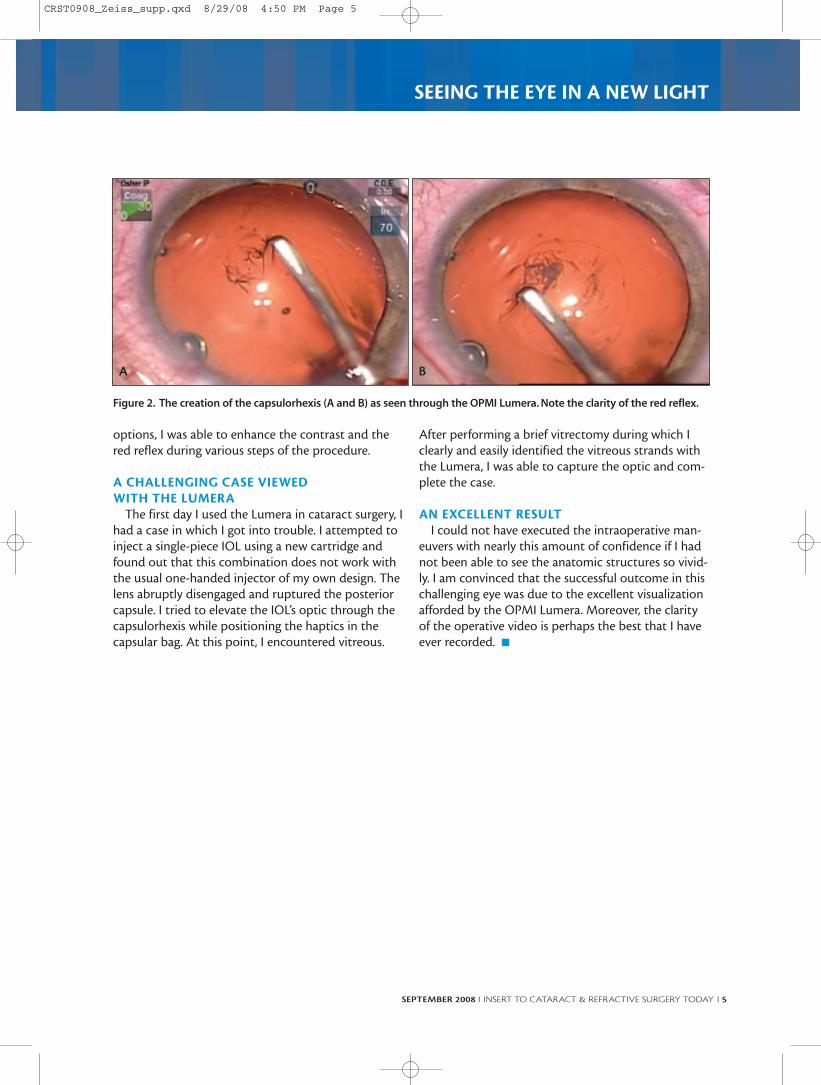
After performing a brief vitrectomy during which Iclearly and easily identified the vitreous strands withthe Lumera, I was able to capture the optic and com-plete the case.
AN EXCELLENT RESULTI could not have executed the intraoperative man-
euvers with nearly this amount of confidence if I hadnot been able to see the anatomic structures so vivid-ly. I am convinced that the successful outcome in thischallenging eye was due to the excellent visualizationafforded by the OPMI Lumera. Moreover, the clarityof the operative video is perhaps the best that I haveever recorded. n
Figure 2. The creation of the capsulorhexis (A and B) as seen through the OPMI Lumera. Note the clarity of the red reflex.
A B
CRST0908_Zeiss_supp.qxd 8/29/08 4:50 PM Page 5
6 I INSERT TO CATARACT & REFRACTIVE SURGERY TODAY I SEPTEMBER 2008
SEEING THE EYE IN A NEW LIGHT
I n my opinion, the introduction of the Version 5Advanced Technology Software for the IOLMaster(Carl Zeiss Meditec, Inc., Dublin, CA) has made a
tremendously useful product even better. Although theearlier versions of the IOLMaster’s software wereimpressive, it was unable to measure the axial length ofsome patients’ eyes. Additionally, its keratometry read-ings suffered from a certain degree of variability. TheIOLMaster’s new Version 5 software is touted for its abil-ity to acquire axial-length measurementsin more patients, which is certainly a bigbenefit. I think a more exciting feature ofthe software, however, is the quality ofthe keratometric data it acquires. Sur-geons can select premium, toric, and mul-tifocal lenses directly from the machine’sK readings. My results have been terrific,and this article describes the value thatthis new software has brought to mypractice.
ROUTINE IS NOW PREMIUMEveryone who works in ophthalmology
today is excited about premium lenses,but I think surgeons forget that their rou-tine cataract patients have really becomepremium IOL patients who expect a pre-mium refractive outcome. Patients judgethe quality of our surgical skills by howclose we can get their refraction to plano,a task that is challenging to achieve with-out accurate biometry. We can do themost difficult phaco surgery in theworld—preserving the capsule in the faceof bad zonules, to name an example—but if the patient ends up +1.50 D, he willthink the surgery was a disaster. So,whereas many surgeons think they willonly invest in the IOLMaster if they get
into premium IOLs, they will find that the device willgreatly benefit them with routine patients as well.
BENEFITS OF THE NEW SOFTWAREThe IOLMaster’s Version 5 software is better able to
filter signal-to-noise ratios than its predecessor, therebyexpanding its range of measurable patients. To me, how-ever, the machine’s greater advantage is its ability to pro-vide very accurate, high-quality keratometric readings
How the technology may be used on a daily basis to help build the practice.
BY RICHARD TIPPERMAN, MD
The IOLMaster’s NewVersion 5 Software
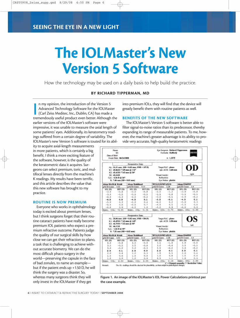
Figure 1. An image of the IOLMaster’s IOL Power Calculations printout per
the case example.
CRST0908_Zeiss_supp.qxd 8/29/08 4:50 PM Page 6
SEPTEMBER 2008 I INSERT TO CATARACT & REFRACTIVE SURGERY TODAY I 7
SEEING THE EYE IN A NEW LIGHT
that I can depend on right out of the box.I do not have to verify my K readingsagainst a different machine or manual ker-atometry, and this increases my office’sefficiency significantly without sacrificingaccuracy.
CASE EXAMPLERecently, I operated on a woman who
had very high myopia. Her right eye was-17.00 D, and her left eye was -14.00 D andhad a scleral buckle. Of course, she want-ed to see perfectly after the surgery. TheIOLMaster’s axial length and keratometricreadings called for a -3.00 D IOL OD anda +4.00 D lens OS (Figures 1 and 2). Al-though this was a large discrepancybetween the two eyes, I have used themachine for so long and have such faithin the software that I believed the meas-urements were sound. I informed thepatient that the discrepancy in her IOLpowers was unusual but that, based onthe readings, I planned to implant thesetwo powers of IOLs. Both of her eyes hittheir refractive target exactly, and she waspleased to achieve a 20/20 result.
Most surgeons would not be comfort-able proceeding with surgery if they gotmeasurements like that with immersionA-scan, and they would probably send the patient some-where else to be measured. The IOLMaster’s Version 5software, however, is invaluable in the way it removesvariability from the measurement process.
VALUE IN THE DAY-TO-DAYI have been surprised at how much the IOLMaster
helps me with routine surgical cases, and this is the pri-mary message I want to convey to surgeons consider-ing its purchase. Not only is my patient flow muchsmoother, but I also have more confidence in my surgicalplanning, because I am able to choose a patient’s implantbased on the machine’s calculations and be as assured aspossible with current technology that I am going tomeet my target refraction.
Because the IOLMaster still cannot measure a smallpercentage of eyes, I have not given up immersion A-scancompletely. I no longer have my technician perform man-ual keratometry routinely, however, and I only use thismethod to take topographic readings from premium IOL
patients. Our primary goal is not to verify the patients’ Kreadings but rather to confirm they do not have anom-alies in their overall topography that might contraindi-cate the implantation of a premium IOL.
MORE HAPPY PATIENTSI think most surgeons now agree that the IOLMaster’s
technology is superior to immersion A-scan, but many ofthem are daunted by the initial financial investment. Iadvise surgeons to consider how their practice andpatients can benefit from the technology. Instead ofinvesting a lot of time and effort counseling (and correct-ing) patients with undesirable refractive outcomes, sur-geons can use the IOLMaster’s Advanced Version 5 soft-ware to avoid missing surgical targets and make morepatients happy. A greater number of happy patients willgrow your practice, and in this way, the machine be-comes quite cost effective. Remember, even if you arestrictly a cataract surgeon, your “product” is giving peo-ple the refractive results they want to achieve. n
Figure 2. An image of the IOLMaster’s IOL Power Calculations printout per
the case example.
CRST0908_Zeiss_supp.qxd 8/29/08 4:50 PM Page 7
8 I INSERT TO CATARACT & REFRACTIVE SURGERY TODAY I SEPTEMBER 2008
SEEING THE EYE IN A NEW LIGHT
When used together, the ATLAS 9000 cornealtopography system, which functions onPlacido-disk technology, and the Visante
OCT Anterior Segment Imaging and Biometry (bothmanufactured by Carl Zeiss Meditec, Inc., Dublin, CA)formulate a more complete and accurate picture of theeye for improved corneal and intraocular surgery.
The Visante OCT, which is slightly larger than a top-ographer, provides exquisite images of the anteriorsegment and clear pictures of the shape of the corneaand the structure of the angles (Figure 1). In someeyes, it can even image the ciliary body. The cornealviews assist in excimer laser surgery and corneal trans-plants, and the intraocular views facilitate treatmentsranging from glaucoma management to phakic IOLimplantation. Roger F. Steinert, MD, and DavidHuang, MD, PhD, coauthored Anterior SegmentOptical Coherence Tomography,1 which is a greatresource for understanding the Visante's capabilities.
The following cases provide examples of how I haveused the ATLAS and Visante OCT within my practiceto optimize surgical outcomes.
CASE NO. 1A 30-year-old white female taking Topamax (topira-
mate; Ortho-McNeil-Janssen Pharmaceuticals, Inc.,Titusville, NJ) for migraines for 2 weeks presented withprogressively declining vision that had reached 20/400.Her refractions were -3.50 D in the right eye and -5.00D in the left (both correctable to 20/20). The VisanteOCT showed that the anterior chambers in both eyeswere relatively shallow and that the angles were ap-proximately 25º (Figure 1). I asked her to discontinuethe Topamax.
At 2 weeks, her vision had returned to 20/20uncorrected with slight hyperopia. The Visanteshowed an obvious dynamic change internally. Theanterior chamber had deepened from an endothelial-anterior lens capsule distance of 2.26 to 2.79 mm. Thegonio angles also opened up from 25º to 43º. Notablechanges in the crystalline lens rise were also seen,with a reduction from 900 µm to 520 µm (Figure 2).
CASE NO. 2A 20-year-old white male with a refraction of -14.25
-2.75 X 115 in the right eye and -11.25 -1.00 X 090 inthe left eye was seeking refractive surgery. My staffand I evaluated the patient for implantation of theVerisyse phakic IOL (Advanced Medical Optics, Inc.,
Linking Placido and OCT for comprehensive topography.
BY AMIN ASHRAFZADEH, MD
Visante OCT Version 3.0
Figure 1. An example of images seen with the Visante OCT.
Figure 2. Intraocular changes after discontinued Topamax.
Figure 3. A Verisyse model superimposed over the actual
implant in the right eye.
CRST0908_Zeiss_supp.qxd 8/29/08 4:50 PM Page 8
SEPTEMBER 2008 I INSERT TO CATARACT & REFRACTIVE SURGERY TODAY I 9
SEEING THE EYE IN A NEW LIGHT
Santa Ana, CA) in the right eye and iLASIK (AdvancedMedical Optics, Inc.) in the left eye. The VeriCalc soft-ware (Advanced Medical Optics, Inc.) calculated thedistance from the Verisyse lens’ edge to the endotheli-um as 1.92 mm. However, the Visante 2.0 softwarewith its phakic IOL model predicted 1.59 mm and acrystalline lens rise of 300 µm. The actual measure-ment after implantation proved to be 1.64 mm.Additionally, the Visante’s preoperative module wasable to predict a 41.67-µm vault distance between
the surface of the anterior crystalline lens and theposterior surface of the Verisyse IOL. The actual dis-tance postoperatively was 38.67 µm. Figure 3 showsthe right eye with the implanted Verisyse superim-posed in a model. It is important to remember thatthe anterior chamber depth is reduced by approxi-mately 20 µm per year, with an increased rise of thecrystalline lens and consequential narrowing of thevault distance. This phenomenon increases the riskfor late postoperative complications.
VISANTE 3.0 SOFTWAREThe newest software upgrade in development,
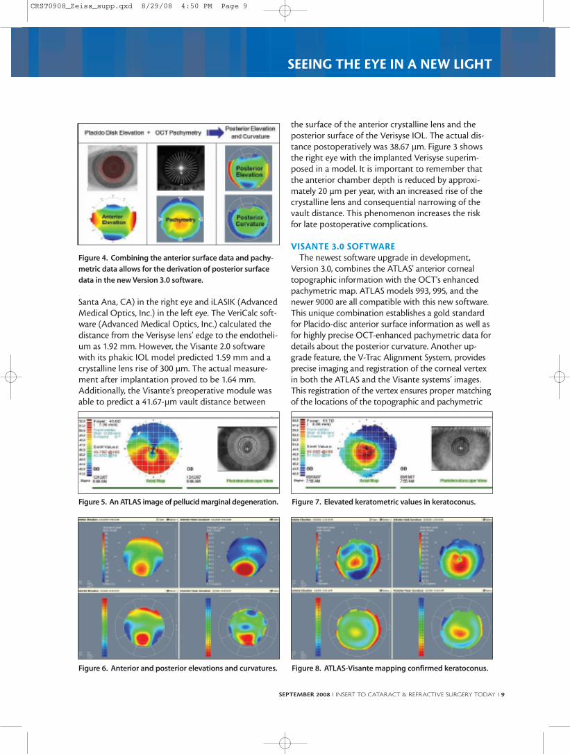
Version 3.0, combines the ATLAS' anterior cornealtopographic information with the OCT's enhancedpachymetric map. ATLAS models 993, 995, and thenewer 9000 are all compatible with this new software.This unique combination establishes a gold standardfor Placido-disc anterior surface information as well asfor highly precise OCT-enhanced pachymetric data fordetails about the posterior curvature. Another up-grade feature, the V-Trac Alignment System, providesprecise imaging and registration of the corneal vertexin both the ATLAS and the Visante systems’ images.This registration of the vertex ensures proper matchingof the locations of the topographic and pachymetric
Figure 4. Combining the anterior surface data and pachy-
metric data allows for the derivation of posterior surface
data in the new Version 3.0 software.
Figure 6. Anterior and posterior elevations and curvatures.
Figure 5. An ATLAS image of pellucid marginal degeneration.
Figure 7. Elevated keratometric values in keratoconus.
CRST0908_Zeiss_supp.qxd 8/29/08 4:50 PM Page 9
10 I INSERT TO CATARACT & REFRACTIVE SURGERY TODAY I SEPTEMBER 2008
SEEING THE EYE IN A NEW LIGHT
data point locations. The screen shows two images:one with Placido-disc mapping, which provides theanterior elevation information, and the pachymetricdata from the Visante (Figure 4). This combinationcan now be used to provide some information on theposterior curvature and elevation.
CASE NO. 3Figure 5 shows the ATLAS image of an eye of a 53-
year-old black female with pellucid marginal degener-ation. The pachymetric map shows corneal thinninginferiorly. Combining the information from theATLAS with the pachymetric map revealed anteriorelevation inferiorly on both the anterior and posteriormean curvature maps as well as the anterior and pos-terior elevation maps (Figure 6). They were all consis-tent with classic pellucid marginal degeneration.
CASE NO. 4In September 2006, I performed a corneal trans-
plant for keratoconus on the left eye of a 13-year-oldwhite male. Although the fellow eye was asympto-matic, over the course of the next year, the mires
changed, and the keratometric values increased from46.00 to 56.00 D (Figure 7). His keratoconus pro-gressed further, and eventually, I performed anIntraLase-enabled keratoplasty (Advanced MedicalOptics, Inc.). Prior to this procedure, his pachymetricdata were regularly concentric and approximately450 µm thin in the center. The ATLAS-Visante com-bined mapping showed the central nipple of thecone, which correlated with the posterior elevation(Figure 8).
CASE NO. 5A 34-year-old white female wanted a LASIK en-
hancement of -0.25 -1.75 X 010. Her initial surgery,which I had performed, was for a refraction of -8.00 -2.75 X 020 with a central pachymetry of 515 µm. In theinitial procedure, I had used the IntraLase FS laser(Advanced Medical Optics, Inc.) to make a 100-µmflap and then applied a CustomVue treatment(Advanced Medical Optics, Inc.). The residual stromaltissue was 270 to 280 µm (Figure 9). Three monthsafterward, I chose to perform a PRK enhancement onthis eye. Figures 10A and B show the postoperativemaps (pre-enhancement) from the ATLAS. The anteri-or elevation map (10A) correlates with the tissue abla-tion. Figure 10B shows the anterior mean curvature.After the enhancement, the posterior elevation map(Figure 10C) appeared perfectly spherical, and the pos-terior mean curvature map (Figure 10D) was unre-markable. Fortunately, this patient is seeing well, andher vision has remained stable postoperatively. This is agood example of a borderline case in which the ATLASand Visante’s data gave me confidence in my chosentreatment course.
SUMMARYIn conclusion, the combination of the Zeiss ATLAS
and the Visante Anterior Segment OCT produces anincredible tool for evaluating the anterior and poste-rior surfaces of the cornea. The devices provide valu-able, dynamic, advanced information for pre-LASIKevaluations as well as follow-up progress. Addition-ally, the Visante's phakic IOL module enables highlyaccurate preoperative implantation evaluations withlens models placed inside the anterior chamber.These combined tools are an incredibly strong assetfor any cornea and refractive surgeon. n
enhancement (A and B), and stable postenhancement pos-
terior surface data (C and D) for case No. 5.
A B
C D
CRST0908_Zeiss_supp.qxd 8/29/08 4:50 PM Page 10
SEPTEMBER 2008 I INSERT TO CATARACT & REFRACTIVE SURGERY TODAY I 11
SEEING THE EYE IN A NEW LIGHT
Several products by Carl Zeiss Meditec, Inc.(Dublin, CA) have achieved the status of goldstandard in many areas of ophthalmology. For
example, the IOLMaster has established itself as thegold standard for cataract evaluation, and the LumeraOPMI appears to be raising the bar for surgical micro-scopes. My clinic has been fortunate to be a studysite for the Visante Topography Link Software, whichlinks the OCT pachymetry with the ATLAS topogra-phy to provide information on the posterior cornealsurface, and the ATLAS PathFinder II Corneal AnalysisSoftware, which has come a long way since its firstversion. The new PathFinder II Software features anadvanced algorithm that I feel accurately predictswhich patients are candidates for corneal refractivesurgery and which are not. For this and other reasons,I find these tools invaluable in my practice.
NEW FEATURESThe original PathFinder Software analyzed three
parameters: the Shape Factor, the Toric KeratometricMean, and the Corneal Irregularity Measurement.The updated PathFinder II is able to provide a much
Clinical experience with the new PathFinder II Corneal Analysis Software and theVisante OCT Topography Link Software.
BY JON G. DISHLER, MD
Easier Patient Selection in Refractive Surgery
Figure 1. Mean curvature provides a local average curvature at each point, which suppresses corneal astigmatism to
reveal the underlying curvature.The Pathfinder II software incorporates nine parameters taken from the Mean Curvature
map.
“The new PathFinder II Software
features an advanced algorithm
that I feel accurately predicts
which patients are candidates for
corneal refractive surgery and
which are not.”
A B
CRST0908_Zeiss_supp.qxd 8/29/08 4:50 PM Page 11
12 I INSERT TO CATARACT & REFRACTIVE SURGERY TODAY I SEPTEMBER 2008
SEEING THE EYE IN A NEW LIGHT
more detailed analysis. The system evaluates an eyeagainst the original three parameters as well as nineother parameters from the new mean curvaturemap. Mean curvature is different from traditionaltopography maps in that it suppresses corneal astig-matism to reveal the underlying curvature at eachpoint (Figure 1). Then, the software uses the sametraffic-light system as the IOLMaster for identifyingany outlying results. Green means that the parameterreadings fall within 90% of the normal population;
yellow is a standard deviation away,from 90% to 98% of the normalpopulation; and red means beyond98%.
PathFinder II also features a data-base of five different clinically recog-nized corneal conditions, as deter-mined by a multicenter clinicalstudy (data on file with Carl ZeissMeditec, Inc.). The conditions arenormal corneas, suspect/clinicalkeratoconus, myopic laser visioncorrection, hyperopic laser visioncorrection, and other unusual con-ditions such as corneal transplants.The software compares these evalu-ations against its clinical databaseto make its determination. The re-sult is a probability that the topo-graphy falls into the five categoriesmentioned previously (Figure 2.).These classifications were proven tobe very accurate in the same clinicaltrial. In fact, when validated againstan independent data set, thePathFinder II’s algorithm demon-strated greater than 90% sensitivity,specificity, and accuracy in detect-ing normal versus abnormalcorneas.1
TAKING THE GUESSWORKOUT OF DIAGNOSES
For years, practitioners thoughtthat corneal thickness was the mainparameter for safe LASIK surgery,but we now know there are manymore factors. Thick corneas canhave ectasia, and thin ones can benormal. It is in these questionable
cases where I think the Visante OCT TopographyLink to the ATLAS becomes invaluable. The followingcase examples demonstrate the utility of the VisanteOCT and ATLAS in clinical practice.
Suspect Keratoconus, Case No. 1Figure 2 shows an eye diagnosed with suspect ker-
atoconus. The axial curvature map looks abnormal,the mean curvature map confirms it, and the diagno-sis is the only one the PathFinder II Software suggests.
Figure 2. The upper left-hand box lists the five clinically recognized corneal
conditions identified that the system uses to label suspect eyes.
Figure 3. A slightly irregular topography, as is commonly seen in clinical
practice.
CRST0908_Zeiss_supp.qxd 8/29/08 4:50 PM Page 12
SEPTEMBER 2008 I INSERT TO CATARACT & REFRACTIVE SURGERY TODAY I 13
SEEING THE EYE IN A NEW LIGHT
This is a relatively straightforward case;the red hot spot is clearly visible in theaxial map.
Suspect Keratoconus, Case No. 2Figure 3 shows a slightly irregular
topography, the kind we see so rou-tinely in clinical practice. The eyemight be normal, or it might be kera-toconic. We do not want to chancemaking a misdiagnosis in today’smedicolegal climate. Compare the pos-terior elevation map and the posteriormean curvature map (Figure 4), whichboth appear very normal. These read-ings confirm that this patient does nothave keratoconus. What makes theVisante-ATLAS Topography so invalu-able to me during these examinationsis the combination of its diagnosticsoftware and back-surface cornealtopography.
Normal or Suspect?Figure 5 is of an eye for which the
diagnosis of normal or keratoconic ismore questionable. On the screen dis-playing both the anterior and posteri-or elevation maps, the posterior datamake the diagnosis more obvious.Note the inserted Visante OCT image(Figure 6), which shows a cross sectionof the thinning directly over the areasof the cornea that are elevated andhave high curvature.
CONCLUSIONI have been very impressed with the
diagnostic capabilities of the ATLASPathFinder II Software and the perform-ance of the Visante OCT TopographyLink Software as well. My staff and Ihave come to rely on these tools in ourclinical practice. n
1. Bagherinia H, Chen X, Flachenecker C, et al. Support
vector machine (SVM)-based classification of corneal topogra-
phy. Poster presented at: The Association for Research in Vision
and Ophthalmology Annual Meeting; April 27, 2008; Fort
Lauderdale, FL.
Figure 5. The posterior data map provides a more obvious confirmation
of keratoconus.
Figure 4. The posterior elevation and mean curvature maps for the sus-
pect keratoconus case No. 2 appear normal.
Figure 6. The inserted Visante OCT image (top right) shows a cross sec-
tion of corneal thinning.
CRST0908_Zeiss_supp.qxd 8/29/08 4:50 PM Page 13
14 I INSERT TO CATARACT & REFRACTIVE SURGERY TODAY I SEPTEMBER 2008
SEEING THE EYE IN A NEW LIGHT
In cataract surgery, we can only treat the irregularitieswe can identify. Fortunately, diagnostic imaging forthe eye is advancing impressively. Carl Zeiss Meditec,
Inc. (Dublin, CA), has developed new software for itsupgraded ATLAS 9000 Corneal Topography System thatI think will prove quite useful for cataract surgeons. Thisinnovation in diagnostic corneal imaging combines thereadings from the ATLAS 9000 with mapping informa-tion from the Visante OCT (also from Carl ZeissMeditec, Inc.) to provide a comprehensive view of theeye. I call this combination ATLAS corneal imaging,because it is more than just topography.
MYRIAD BENEFITSMeeting Higher Expectations
Routinely performing corneal topography on cat-aract patients helps us assess the effect of corneal aber-rations—whether lower- or higher-order, and includingcylinder, irregular, or asymmetric—on patients’ visualoutcomes. The ability to preoperatively discern certaincorneal pathologies and more accurately select IOL
implants is especially important for premium IOLpatients, who expect excellent postoperative results.Technology such as the ATLAS 9000 system will help usmeet their expectations.
Ocular Alignment for MappingOne of the issues we surgeons have with any scan-
ning technology, whether it is used in the anterior orposterior segment, is reproducibly achieving properalignment with the eye’s axes to ensure reliable map-ping. The ATLAS 9000 and Visante OCT have new fea-tures to improve this function. When conducting topo-graphical mapping, we are used to working with a vari-ety of curvature maps, such as axial, tangential, andmean curvature. These same data maps can be devel-oped from simulated keratometry and videokerato-scopy and evaluated with a topographical device.
Astigmatism ManagementThe use of corneal topography in astigmatic treat-
ments, whether using lenticular or corneal methods, is asomewhat new area of diagnosis that is generating greatinterest. As cataract and refractive surgeons implantmore premium IOLs, it is becoming increasing impor-tant to manage astigmatism. Corneal curvature maps
Corneal imaging that is more than just topography.
BY IQBAL IKE K. AHMED, MD, AND JENNIFER CALAFATI, MD
Novel Applications ofATLAS Corneal Topography
for the Cataract Surgeon
Figure 1. An eye with mild against-the-rule cylinder.
“The ability to preoperatively
discern certain corneal patholo-
gies and more accurately select
IOL implants is especially impor-
tant for premium IOL patients.”
CRST0908_Zeiss_supp.qxd 8/29/08 4:50 PM Page 14
SEPTEMBER 2008 I INSERT TO CATARACT & REFRACTIVE SURGERY TODAY I 15
SEEING THE EYE IN A NEW LIGHT
can be quite helpful for surgeons to plan the placementof limbal relaxing incisions and toric IOLs along theappropriate axis. For example, Figure 1 shows a patientwith a little bit of against-the-rule cylinder. The surgeoncould choose to make two limbal relaxing incisions toflatten the steep axis, or he may decide to place a toricIOL in an equal but opposite power.
Corneal AberrationsThe new ATLAS 9000 software offers several diagnostic
features that provide additional information about cor-neal aberrations. One particularly advantageous functionis image simulation, which shows patients an example ofhow an eye chart may appear to them under the influ-ence of their corneal aberration. This application alsohelps surgeons to explain why patients may still not seeclearly after cataract surgery and why they may needadditional treatment to correct certain aberrations.
The software’s modulation transfer function andZernike analysis can be used to further customize IOLtechnology. With three choices of aspheric IOLs available(the Tecnis [Advanced Medical Optics, Inc., Santa Ana,CA], the AcrySof IQ [Alcon Laboratories, Inc., Fort Worth,TX], and the Sofport AO [Bausch & Lomb, Rochester,NY]), how can we select the most appropriate lens for thepatient? The ATLAS gives us the ability to determinecorneal spherical aberration (Figure 2, arrow), which, asGeorge Beiko, MD, found in a large population of cataractpatients,1 can vary widely. By determining the patient’sspecific corneal aberration, we can select the appropriateIOL to correct the entire amount or leave some residualspherical aberration, depending on the patient’s visualpreferences. This is how we can use the ATLAS to cus-tom-select corrective lenses for our patients.
PupillometryI find pupillometry to be increasingly important in
both LASIK and cataract surgery. We know that pupilsize can play a role in IOL selection. For example,pupils smaller than 2 mm may not experience suffi-cient near vision from refractive multifocal IOLs, andpupils that are too large may have suboptimal experi-ences with diffractive lenses. Larger pupils may alsobe at risk for dysphotopsia. Figure 3 shows scotopicand photopic imaging of the pupil with the ATLAS.Note the difference in the pupil size of two differentpatients under scotopic and photopic lighting. Thiscomparison demonstrates that due to the relative sizeof the pupil, one particular multifocal IOL may bepreferred over the other in consideration of light con-ditions. Obviously, the utility of this technology isvery exciting.
CONCLUSIONSAs I have tried to illustrate in this overview, I see mul-
tiple potential applications for the ATLAS technologies,which I consider to be beyond corneal topography. Asophthalmologists adopt more advanced surgical tech-niques, we need measurements that we can trust, and Ihave confidence in the reliability of Carl Zeiss Meditec’sdevices. The use of corneal topography in managingperioperative astigmatism, the assessment of higher-order corneal aberration, aspheric IOL selection, andthe use of pupillometry in multifocal IOL preference arejust some of the potential uses of the ATLAS 9000 forthe cataract surgeon. n
1. Beiko GH, Haigis W, Steinmueller A. Distribution of corneal spherical aberration in a compre-hensive ophthalmology practice and whether keratometry can predict aberration values. JCataract Refract Surg. 2007;33(5):848-858.
Figure 2. A Zernike analysis of the corneal wavefront
shows the patient’s corneal spherical aberration (arrow).
Figure 3. A sample screen shows how the ATLAS pupillom-
etry can influence IOL selection.
CRST0908_Zeiss_supp.qxd 8/29/08 4:50 PM Page 15
COR.1949
The future of red reflex is now
Let there be lightCRST0908_Zeiss_supp.qxd 8/29/08 4:51 PM Page 16


![SERVICEMANUAL - ProSites, Inc.c1-preview.prosites.com/106982/wy/docs/Kaeser T Series... · TechnicalSpecification 2---4 2.4 PressureSwitchSetting Factorysetting Cut–inpressure[psig]](https://static.documents.pub/doc/80x56/60740cba46f685632c726a02/servicemanual-prosites-incc1-t-series-technicalspecification-2-4-24.jpg)


