SEG-D, REVISION 11 Prepared by the SEG Field Tape Standards Subcommittee: Richard Allen, SYNTRON; Gary Crews, ARCO Oil and Gas Co.; William Guyton, Western At/as International; C. S. Rapp, Exxon Production Research Co.; Clifford A. McLemore, Serce/ /nc.; Bob Peterson, Mobil Oil Corp.; Leon Walker, GECO; Larry R. Whigham, Shell Development Co.; David A. White, Input/Output, Inc.; George Wood, Halliburton Energy Services.
SEG-D CHANGES A number of additions are being made to the SEG-D field tape format to make the format more useful in the current seismic data acquisition environment. These changes are intended to address the majority of short term needs in the industry today. A more extensive revision to the field tape format will be required within the next few years in order to address long term needs. The new format will be called "SEG-D, Revision 1", indicating that it is a revised version of the original format. If the expanded features provided in Revision 1 are not used, then the format is compatible with the original SEG-D format.
SPECIFIC CHANGES: 1. To allow for additional defined fields in SEG-D headers, additional blocks are allowed for the General
Header and Demux Trace Header. 2. Adding provision for an optional set of General Trailer blocks. This type header allows provisions for
recording auxiliary seismic system and real-time navigation related data in the trailer. The trailer is optional and typically follows all other recorded data. The addition of the trailer will allow the accumulation of system faults, data QC information, real-time navigation position, and timing information on the same tape, and contiguous with, the shotpoint that it relates to. By recording this data after all of the other data, additional time is provided for collecting the data and transferring it to the recording system. The Trailer blocks take the same general form as the Channel Set Descriptor. Byte 11 uses the "Channel Type Identification" set to 1100 to indicate a Trailer block. Bytes 1 and 2 indicate the number of the General Trailer block, with the first block numbered as 1. Ail other information in the trailer is optional and may be formatted as desired by the manufacturer/user. The number of General Trailer blocks is indicated in bytes 13 and 14 of General Header Block #2.
3. Providing provision to include the revision of SEG-D format. Added to Bytes 11 and 12 of General Header Block #2 contain the SEG-D Revision Number. The revision number is a 16 bit unsigned binary number. The Revision number is 1 for the proposed version. In addition, in the General Header Block #1, nibble 1 of byte 12 contains the number of additional blocks in the general header. Nibble 1, byte 12 is an unsigned binary number. This number will be 1 or greater for SEG D Rev 1.
4. Adding provision to include the source and receiver locations for each source and receiver location. Source locations are included in the General Header Blocks. Block #3 contains the position for Source Set #1. Additional General Header Blocks may be included to allow for additional Source Sets. Source
This document has been converted from the original publication: SEG Comm. Field Tape Std., 1994, Digital field tape standards - SEG-D, revision 1 (special report): Geophysics, 59, no. 04, 668-684.
2 of 32
positions are defined by a Source Line Number (three bytes integer and two bytes fraction), a Source Point Number (three bytes integer and two bytes fraction), and a Source Point Index (one byte). This index allows several locations for the source in the grid, the original value is 1 and that value is incremented by 1 every time the source is moved, even when it is moved back to a previous location). Receiver locations are included in Trace Header Extensions to be used with Demux Trace Headers. Receiver positions are defined by a Receiver Line Number (three integer bytes and two fraction bytes), a Receiver Point Number (three bytes integer and two bytes fraction), and a Receiver Point Index (one byte). This index allows for defining the receiver group in the grid, the original value is 1 and that value is incremented by 1 every time the receiver is moved, even when it is moved back to the previous location).
5. Providing for the use of File Numbers greater than 9999. Bytes 1,2, and 3 in General Header Block #2 allow for a three byte, binary file number. When the file number is greater than 9999, bytes 1 and 2 in the General Header Block #1 must be set to FFFF.
6. Providing for Extended Channel Sets/Scan Types. General Header Block #2 allows for a two byte, binary number of Channel Sets/Scan Types in bytes 4 and 5. When using the Extended Channel Sets/Scan Types, byte 29 of General Header #1 must be set to FF.
7. Providing for additional Extended and External Header blocks. General Header Block #2 bytes 6 and 7 (for Extended Header blocks) and Bytes 8 and 9 (for External Header blocks) allow the use of a two byte, binary number to allow more than 99 blocks. When using these capabilities, General Header Block #1 byte 31 (for extended) and byte 32 (for external) must be set to FF.
8. Providing a mechanism for recording additional information about vibratory sources. Byte 15 of the General Header Block #N indicates the signal used to control vibrator phase. Byte 16 indicates the type of vibrator (P, Shear, Marine). Bytes 28 and 29 contain the phase angle between the pilot and the phase feedback signal. The additional vibrator information may be recorded for multiple sets of sources by using additional General Header blocks.
9. Providing for larger number of samples per trace. Using bytes 8, 9, and 10 of the Trace Header Extension.
10. Providing provisions for using 1/2" square tape cartridges. ( ANSI X3.180 1989). 11. Allowing recording data in IEEE and other new formats.
Additional Valid Format Codes for bytes 3 & 4 of the General Header are: 0036 24 bit 2's compliment integer multiplexed 0038 32 bit 2's compliment integer multiplexed 0058 32 bit IEEE multiplexed 8036 24 bit 2's compliment integer demultiplexed 8038 32 bit 2's compliment integer demultiplexed 8058 32 bit IEEE demultiplexed The IEEE format is fully documented in the IEEE standard, "ANSI/IEEE Std 754 - 1985", available from the IEEE. The IEEE format is summarized as follows:
3 of 32
The value (v) of a floating-point number represented in this format is determined as follows: if e = 255 & f ≠ 0 . . v = NaN Not-a-Number (see Note 2) if e = 255 & f = 0 . . v = (-1)8 * ∞ Overflow if 0 < e < 255 v = (-1)8 * 2-127 *(1 .f) Normalized if e = 0 & f ≠ 0...v = (-1)8 * 2-126 * (0.f) Denormalized if e = 0 & f = 0...v = (-1)8 * 0 ±zero where e = binary value of all C's (exponent) and f = binary value of all Q's (fraction) NOTES: 1. Bit 7 of byte 4 must be zero to guarantee uniqueness of the start of scan in the Multiplexed
format (0058). It may be non zero in the demultiplexed format (8058). 2. A Not-a-Number (NAN) is interpreted as an invalid number. All other numbers are valid and
interpreted as described above. 12. Allowing for the use of blocked records. Allow blocked demultiplexed data (integral number of traces
in a block). Headers will not be blocked. All records in a block will be the same size. Not all blocks will be the same size. Byte 20 in the general header (B1 = 1) will indicate blocked data. Blocks will be limited to 128 kilobytes. All traces in a block are in the same Channel Set.
13. Adding the acceptance of ANSI standard X3.27 as the SEG standard for tape labels - as an option. This will be to cover only the label on the magnetic media, it does not cover an external label.
14. Adding the effective stack order (unsigned binary), in byte 30 in the Channel Set descriptor. Set to 0 if the trace data was intentionally set to real 0. Set to 1 if no stack. Set to the effective stack order if the data is the result of stacked data (with or without processing).
15. Improving definition of undefined fields. All undefined fields will be specified as: "This field is undefined by this format".
16. Adding provisions for a Trace Edit byte (byte 10 of Demux Trace Header) to indicate traces zeroed for roll-on or roll-off and to indicate deliberately zeroed traces. TR=0 No edit of this trace, TR=1 Trace part of dead channels for roll-on or roll-off spread; trace intentionally zeroed. TR=2 Trace intentionally zeroed.
17. Increasing precision of MP factor, using byte 7 of the Channel Set descriptor. 18. Since modern seismic vessels record more than one streamer at a time, a standard convention is
required to identify which streamer recorded each channel of data. The Channel Set Descriptors are updated to handle this task. The definition of a channel set is expanded to include the following rules. A channel set is a group of channels that:
(a) Use identical recording parameters. This includes the same record length and sample interval. (b) Use identical processing parameters, including the same filter selection and array forming
parameters. A field has been added to Channel Set Descriptor byte 32 to describe any array forming applied to data in that channel set.
(c) Originates from the same streamer cable for manne data. The streamer cable number for each channel set has been added to Channel Set Descriptor byte 31.
(d) Consists of channels with the same group spacing. For example, if one steamer has short group spacing close to the boat and longer groups spacing at long offsets, the data from that streamer would be recorded as two channel sets. In addition, the first channel in each channel set will start with Trace number one.
19. Correcting the MP factor calculation (refer to Appendix E7 in the SEG-D recording format description). MP CALCULATION The calculation of MP for a data recording method is given by one of the following equations: (a) MP = FS - PA - Cmax; for binary exponents, (b) MP = FS - PA - 2 x Cmax; for quaternary exponents, (c) MP = FS - PA - 4 x Cmax; for hexadecimal exponents (except the 4 byte excess 64 method), (d) MP = FS - PA - 4 (Cmax - 64); for excess 64 hexadecimal exponents and for 4 byte IEEE
exponents,where: 2FS= Converter full scale (millivolts), 2PA = Minimum system gain, and Cmax = maximum value of the data exponent, Cmax = 15 for binary exponents, 7 for quaternary exponents, 3 for hexadecimal exponents except excess 64; and 64 for excess 64 exponents and for 4 byte IEEE exponents.
20. Adding the option for using record lengths in millisecond increments (rather than the previous 0.5 second increments). The Extended Record Length is the record ~ength, in unsigned binary milliseconds, and is recorded in bytes 15-17 in General Header Block #2. If this option is used, Record Length (R), in the General Header Block #1, bytes 26, 27 must be set to FFF.
HEADER BLOCK PARAMETERS General Header, Block #1 All values are in packed BCD unless otherwise specified. Index Byte Abbreviation Description
1 F1, F2
2 F3, F4
File number of four digits (0 - 9999), set to FFFF when the file number is greater than 9999. The expanded file number is contained in Bytes 1, 2, & 3 of General Header, Block #2.
3 Y1, Y2
4 Y3, Y4
Format code: 0015 20 bit binary multiplexed 0022 8 bit quaternary multiplexed 0024 16 bit quaternary multiplexed 0036 24 bit 2's compliment integer multiplexed 0038 32 bit 2's compliment integer multiplexed 0042 8 bit hexadecimal multiplexed 0044 16 bit hexadecimal multiplexed 0048 32 bit hexadecimal multiplexed 0058 32 bit IEEE multiplexed 8015 20 bit binary demultiplexed 8022 8 bit quaternary demultiplexed 8024 16 bit quaternary demultiplexed 8036 24 bit 2's compliment integer demultiplexed 8038 32 bit 2's compliment integer demultiplexed 8042 8 bit hexadecimal demultiplexed 8044 16 bit hexadecimal demultiplexed 8048 32 bit hexadecimal demultiplexed 8058 32 bit IEEE demultiplexed 0200 Illegal, do not use 0000 Illegal, do not use
5 K1, K2 6 K3, K4
7 K5, K6
8 K7, K8 9 K9, K10
10 K11, K12
General constants, 12 digits
11 YR1, YR2 Last two digits of year (0-99)
GH1 Number of additional Blocks in General Header (unsigned binary). This number will be 1 or greater for SEG-D Rev 1. 12
DY1
13 DY2, DY3
Julian day 3 digits (1-366)
14 H1, H2 Hour of day 2 digits (0-23) (Greenwich Mean Time 15 MI1, MI2 Minute of hour 2 digits (0-59)
9 of 32
General Header, Block #1 All values are in packed BCD unless otherwise specified. Index Byte Abbreviation Description
16 SE1, SE2 Second of minute 2 digits (0-59)
17 M1, M2 Manufacturer's code 2 digits Note: See Appendix B for the current assignments
18 M3, M4
19 M5, M6
Manufacturer's serial number, 4 digits
20 B1, B2 21 B3, B4
22 B5, B6
Bytes per scan 6 digits (1 - 999,999) are utilized in the multiplexed formats to identify the number of bytes (including data, auxiliary, sync, and timing bytes, etc.) required to make up a complete scan. In a demultiplexed record, this field is not used and is recorded as zeros. (See Appendix E2 of the SEG-D Standard).
23 I3 thru I-4
Base scan interval,--This is coded as a binary number with the LSB equal to 1/16 msec. This will allow sampling intervals from 1/16 through 8 msec in binary steps. Thus, the allowable base scan intervals are 1/16, 1/8, 1/4, 1/2, 1, 2, 4, and 8 msec. The base scan interval is always the difference between successive timing words. Each channel used will be sampled one or more times per base scan interval.
P
Polarity, --These 4 binary bits are measured on the sensors, cables, instrument, and source combination and are set into the system manually. The codes are: 0000 Untested 0001 Zero 0010 45 degrees 0011 90 degrees 0100 135 degrees 0101 180 degrees 0110 225 degrees 0111 270 degrees 1000 315 degrees 1001 1010 1011 1100 unassigned 1101 1110 1111
24
S/BX3 thru S/BX0 This binary number (range 0 to 15) is an exponent of 2 and is used in conjunction with S/B (Byte 25).
10 of 32
General Header, Block #1 All values are in packed BCD unless otherwise specified. Index Byte Abbreviation Description
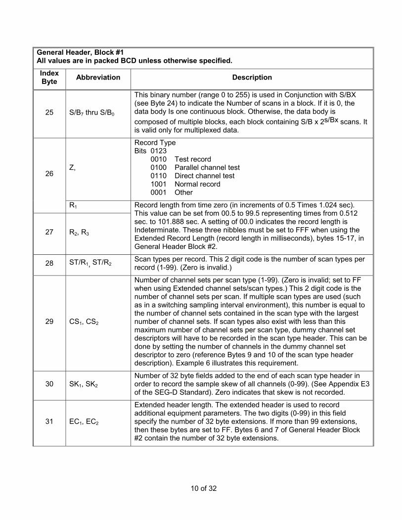
25 S/B7 thru S/B0
This binary number (range 0 to 255) is used in Conjunction with S/BX (see Byte 24) to indicate the Number of scans in a block. If it is 0, the data body Is one continuous block. Otherwise, the data body is composed of multiple blocks, each block containing S/B x 2s/Bx scans. It is valid only for multiplexed data.
Z,
Record Type Bits 0123 0010 Test record 0100 Parallel channel test 0110 Direct channel test 1001 Normal record 0001 Other
26
R1
27 R2, R3
Record length from time zero (in increments of 0.5 Times 1.024 sec). This value can be set from 00.5 to 99.5 representing times from 0.512 sec. to 101.888 sec. A setting of 00.0 indicates the record length is Indeterminate. These three nibbles must be set to FFF when using the Extended Record Length (record length in milliseconds), bytes 15-17, in General Header Block #2.
28 ST/R1, ST/R2 Scan types per record. This 2 digit code is the number of scan types per record (1-99). (Zero is invalid.)
29 CS1, CS2
Number of channel sets per scan type (1-99). (Zero is invalid; set to FF when using Extended channel sets/scan types.) This 2 digit code is the number of channel sets per scan. If multiple scan types are used (such as in a switching sampling interval environment), this number is equal to the number of channel sets contained in the scan type with the largest number of channel sets. If scan types also exist with less than this maximum number of channel sets per scan type, dummy channel set descriptors will have to be recorded in the scan type header. This can be done by setting the number of channels in the dummy channel set descriptor to zero (reference Bytes 9 and 10 of the scan type header description). Example 6 illustrates this requirement.
30 SK1, SK2 Number of 32 byte fields added to the end of each scan type header in order to record the sample skew of all channels (0-99). (See Appendix E3 of the SEG-D Standard). Zero indicates that skew is not recorded.
31 EC1, EC2
Extended header length. The extended header is used to record additional equipment parameters. The two digits (0-99) in this field specify the number of 32 byte extensions. If more than 99 extensions, then these bytes are set to FF. Bytes 6 and 7 of General Header Block #2 contain the number of 32 byte extensions.
11 of 32
General Header, Block #1 All values are in packed BCD unless otherwise specified. Index Byte Abbreviation Description
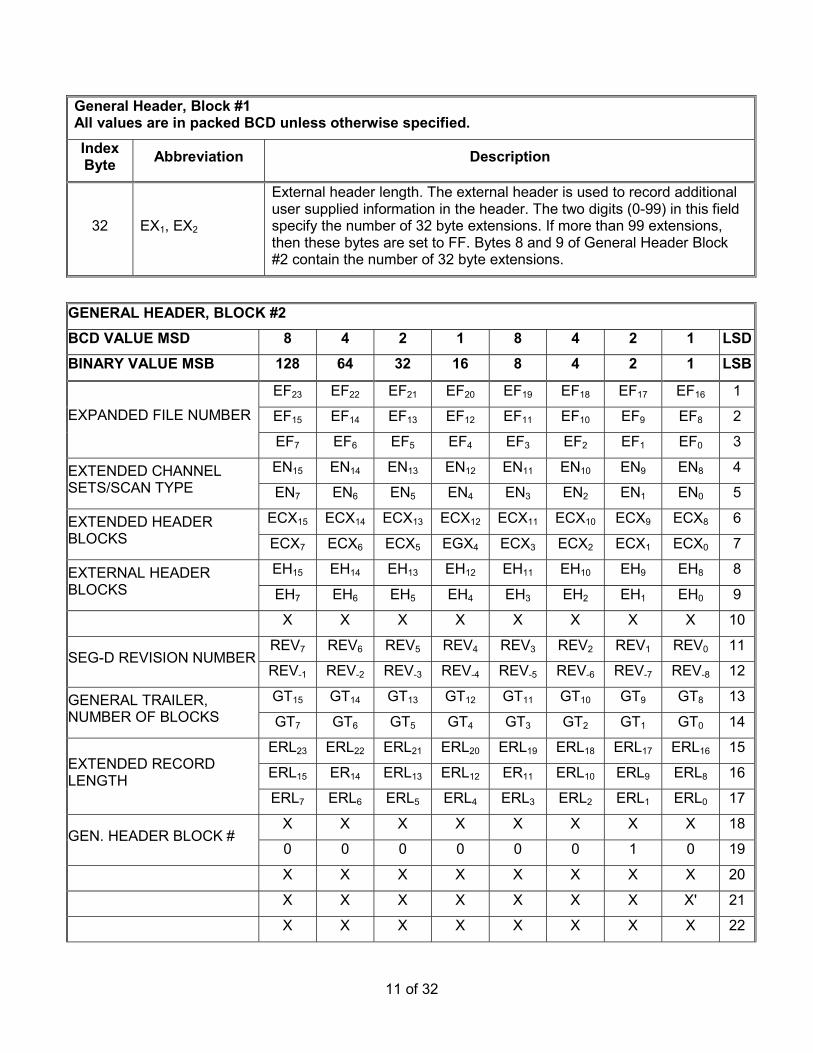
32 EX1, EX2
External header length. The external header is used to record additional user supplied information in the header. The two digits (0-99) in this field specify the number of 32 byte extensions. If more than 99 extensions, then these bytes are set to FF. Bytes 8 and 9 of General Header Block #2 contain the number of 32 byte extensions.
GENERAL HEADER, BLOCK #2 BCD VALUE MSD 8 4 2 1 8 4 2 1 LSD BINARY VALUE MSB 128 64 32 16 8 4 2 1 LSB
GENERAL HEADER, BLOCK #2 BCD VALUE MSD 8 4 2 1 8 4 2 1 LSD BINARY VALUE MSB 128 64 32 16 8 4 2 1 LSB
X X X X X X X X 23
X X X X X X X X 24
X X X X X X X X 25
X X X X X X X X 26
X X X X X X X X 27
X X X X X X X X 28
X X X X X X X X 29
X X X X X X X X 3O
X X X X X X X X 31
X X X X X X X X 32
13 of 32
GENERAL HEADER BLOCK #2 Index Byte Abbreviation Description
1,2,3 EF23 – EF0 Expanded File Number (three bytes, unsigned binary). For file numbers greater than the 9999, bytes 1 and 2 of the General Header Block #1 must be set to FFFF.
4,5 EN15 – EN0
Extended Channel Sets/Scan Types (two bytes, unsigned binary). Allows the number of Channel Sets/Scan Types to be greater than the 99 allowed in the standard General Header (byte 29). When using the Extended Channel Sets/Scan Types, byte 29 of General Header Block #1 must be set to FF.
6,7 ECX15 – ECX0
Extended Header Blocks (two bytes, unsigned binary). Allows the number of Extended Header Blocks (of 32 bytes each) to be greater than the 99 allowed by the standard General Header (byte 31). To use more than 99 Extended Header Blocks, set byte 31 of General Header Block #1 to FF, and usethese two bytes.
8,9 EH15 – EH0
External Header Blocks (two byte, unsigned binary). Allows the number of 32 byte External Header Blocks to be greater than the 99 allowed by the General Header (byte 32). To use more than 99 External Header Blocks, set byte 32 of General Header Block #1 to FF, and use these two bytes.
10 X These fields are undefined by the format and may have any value.
11, REV7 – REV0
12 REV-1 – REV-8
13,14 GT15 – GT0
SEG-D Revision Number (One byte unsigned binary with one byte binary fraction. Revisions 0 to 0.N are not valid.). This version is Rev 1.00.Number of Blocks of General Trailer (two bytes, unsigned binary). The number of 32 byte blocks to be used to General Trailers.
15,16,17 ERL23 – ERL0
Extended Record Length (three bytes, unsigned binary) indicates the record length in milliseconds. When using Extended Record Length, the Record Length in the General Header Block #1 (bytes 26,27) must be set to FFF.
18 X These fields are undefined by format and may have any value.
19 BN7 – BN0 General Header Block Number (one byte unsigned binary), set to 2 for this block. Zero is not valid.
20 – 32 X These fields are undefined by format and may have any value.
NOTES: 1. Where the range of allowable numbers is not indicated, the follow ranges apply.
One byte unsigned binary, range is 0 - FF, Two byte unsigned binary, range is 0 - FFFF, Three byte, two's complement, signed binary; range is - 7FFFFF to +7FFFFF
14 of 32
GENERAL HEADER, BLOCK N BCD VALUE MSD 8 4 2 1 8 4 2 1 LSD BINARY VALUE MSB 128 64 32 16 8 4 2 1 LSB
SOURCE SET NUMBER SS7 SS6 SS5 SS4 SS3 SS2 SS1 SS0 20
X X X X X X X X 21
X X X X X X X X 22
X X X X X X X X 23
X X X X X X X X 24
X X X X X X X X 25
X X X X X X X X 26
X X X X X X X X 27
X X X X X X X X 28
X X X X X X X X 29
15 of 32
GENERAL HEADER, BLOCK N BCD VALUE MSD 8 4 2 1 8 4 2 1 LSD BINARY VALUE MSB 128 64 32 16 8 4 2 1 LSB
X X X X X X X X 30
X X X X X X X X 31
X X X X X X X X 32
GENERAL HEADER BLOCK #N (N Greater than 2) Index Byte Abbreviation Description
1,2,3 X These fields are undefined by format and may have any value.
4,5,6 SLNS,SLN22 –SLN0 Source Line Number, Integer (three bytes, two's complement, signed binary). General Header Block #2 contains the source location for one Source Set. Additional General Header Blocks may be used to provide position information for additional source sets.
7,8 SLN-1 – SLN-16 Source Line Number, Fraction
9,10,11 SPNS, SPN22 – SPN0 Source Point Number, Integer (three bytes, two's complement, signed binary).
12,13 SPN-1 – SPN-16 Source Point Number, Fraction.
14 SPI7 – SPI0 Source Point Index (one byte, unsigned binary). This index allows several locations for the source in the grid, the original value is one and that value is incremented by one every time the source is moved, even when it is moved back to a previous location. Zero value means that the Source Point Index is not recorded.
16 V7 – V0 Type Vibrator (unsigned binary). Type not recorded 00 P wave vibrator 01 Shear wave vibrator 02 Marine vibrator 03 Other types may be added later.
17,18 PAS , PA14 – PA0 Phase Angle (two bytes, two's complement, signed binary). The Phase angle of the intercept of the pilot signal with respect to the phase feedback signal, measured in degrees. Phase Angle is set to zero when Phase Control (Byte 15) is zero (Phase Control not recorded).
19 BN7 – BN0 General Header Block Number (one byte unsigned binary). Set to N for this block. Zero is not valid.
20 SS7 – SS0 Source Set Number (unsigned binary). Used to allow multiple sets of sources. Zero is not valid.
16 of 32
GENERAL HEADER BLOCK #N (N Greater than 2) Index Byte Abbreviation Description
21-32 X These fields are undefined by format and may have any value.
17 of 32
Scan type header (channel set descriptor) The scan type header is determined by the system configuration and consists of one or more channel set descriptors each of 32 bytes followed by a series of 32 byte sample skew fields. A channel set is defined as a group of channels operating with the same set of parameters and being sampled as part of a scan of data. A scan type header can be composed of from 1 to 99 channel set descriptors. If dynamic parameter changes are required during the recording, additional scan type headers must be added, each containing the channel set descriptors necessary to define the new parameters. Each scan type header must have the same number of channel set descriptors (see Appendix E4 of the SEG-D standard for header length calculation).
CHANNEL SET DESCRIPTOR Index Byte Abbreviation Description
1
ST1, ST2 These two digits (1-99) identify the number of the scan type header to be described by the subsequent bytes. The first scan type header is 1 and the last scan type header number is the same value as Byte 28 (ST/R) of the General Header Block #1. If a scan type header contains more than one channel set descriptor, the scan type header number will be repeated in each of its channel set descriptors. If the system does not have dynamic parameter changes during the record, such as switched sampling intervals, there will only be one scan type header required.
2
CN1, CN2 These two digits (1-99) identify the channel set to be described in the next 30 bytes within this scan type header. The first channel set is "1" and the last channel set number is the same number as Byte 29 (CS) of the General Header Block #1. If the scan actually contains fewer channel sets than CS, then dummy channel set descriptors are included as specified in Byte 29 of General Header Block #1. Set to FF when using Channel Sets beyond 99.
3 TF16 thru TF9
4 TF8 thru TF1
Channel set starting time. This is a binary number where TF1 = 21 msec (2-msec increments). This number identifies the timing word of the first scan of data in this channel set. In a single scan type record, this would typically be recorded as a zero (an exception might be deep water recording). In multiple scan type records, this number represents the starting time, in milliseconds, of the channel set. Start times from 0 to 131,070 msec (in 2-msec increments) can be recorded.
5 TE16 thru TE9
6 TE8 thru TE1
Channel set end time. This is a binary number where TE1 = 21 milliseconds (2 millisecond increments). These two bytes represent the record end time of the channel set in milliseconds. In a multiplexed record, all channels of a channel set must be of the same length. TE may be used in a demultiplexed record to allow the termination of a particular channel set shorter than other channel sets within its scan type. In a single scan type record, bytes 5 and 6 would be the length of the record. End times up to 131,070 msec (in 2-msec increments) can be recorded.
7 MP-3, MP-10 Optional byte which extends the resolution available for MP factor.
18 of 32
CHANNEL SET DESCRIPTOR Index Byte Abbreviation Description
8 MPS, MP4 thru MP-2
This sign magnitude binary number is the exponent of the base 2 multiplier to be used to descale the data on tape to obtain input voltage in millivolts. The radix point is between MP0 and MP-1. This multiplier has a range of 231.75 to 2-31.75. (See Appendix E7 of the SEG-D Standard.)
9 C/S1, C/S2
10 C/S3, C/S4
This is the number of channels in this channel set. It can assume a number from 0-9999.
11 C1, 0
Channel type identification: 0123 Bits 0111 Other 0110 External Data 0101 Time counter2 0100 Water break 0011 Up hole 0010 Time break 0001 Seis 0000 Unused 1000 Signature/unfiltered 1001 Signature/filtered 1100 Auxiliary Data Trailer
12 S/C
This packed BCD number is an exponent of 2. The number (2s/c) represents the number of subscans of this channel set in the base scan. Possible values for this parameter (2s/c) are 1 to 512 (20 to 29). Reference Byte 23 of the General Header Block #1.
12 J Channel gain control method.
13 AF1, AF2 14 AF3, AF4
Alias filter frequency. It can be coded for any frequency from 0 to 9999 Hz.
15 0, AS1
16 AS2, AS3
Alias filter slope in dB per octave. It can be coded from 0 to 999 dB in 1-dB steps. A zero indicates the filter is out (see Appendix E5 for definition).
17 LC1, LC2
18 LC3, LC4
Low-cut filter setting. It can be coded for any frequency from 0 to 9999 Hz.
19 0, LS1
20 LS2, LS3
Low-cut filter slope. It can be coded for any slope from 0 to 999 dB per octave. A zero slope indicates the filter is out. (See Appendix E5 for definition.)
2 Illegal code for this format because the timing counter is part of the start of scan and cannot be identified as part of a channel.
19 of 32
CHANNEL SET DESCRIPTOR Index Byte Abbreviation Description
21 NT1, NT2
22 NT3, NT4
Notch frequency setting. It can be coded for any frequency from 0 to 999.9 Hz. The out filter is written as 000.0 Hz.
The following notch filters are coded in a similar manner:
23 NT1, NT2 24 NT3, NT4
Second notch frequency
25 NT1, NT2 26 NT3, NT4
Third notch frequency
27,28 ECS15 – ECS0
Extended Channel Set Number (two byte unsigned binary). Contains the complete value that is (or should have been) contained in byte two (CN,,CN2). Allows additional Channel Sets, beyond the 99 which can be described in byte two. When using Channel sets beyond 99, or when using binary numbers for the Channel Set Number, set byte 2 (CN,, CN2) to FF.
29 EFH3 – EFH0 Extended Header flag (one nibble, four bits, unsigned binary). Set to 1 to indicate that the extended header contains additional information on the channel set.
30 VS7 – VS0
Vertical Stack (one byte, unsigned binary). Effective stack order. Set to zero if the trace data was intentionally set to real zero. Set to one if no stack. Set to the effective stack order if the data is the result of stacked data (with or without processing).
31 CAB7 – CAB0
Streamer Cable number (8 bit unsigned binary). Required for streamer data only. Identifies the number of the streamer cable that will be identified in this block. The starboard-most cable is identified as cable 1 while the Port most cable is N. Zero means that the Streamer Cable number has not been recorded.
32 ARY7 – ARY0
Array Forming (8 bit binary). Identifies whether thedata in this channel set is the result of array forming. 01 Hex No array forming. 02 Hex 2 groups summed, no weighting. 03 Hex 3 groups summed, no weighting. 04 Hex 4 groups summed, no weighting. 0N Hex N groups summed, no weighting. 1N Hex N groups weighted, overlapping, summation.
20 of 32
Scan Type Header (Channel Set Descriptor) Bit 0 1 2 3 4 5 6 7 BCD VALUE MSD 8 4 2 1 8 4 2 1 BINARY VALUE MSB 128 64 32 16 8 4 2 1
SCAN TYPE NUMBER ST1 ST1 ST1 ST1 ST2 ST2 ST2 ST2 1
CHANNEL SET NUMBER CN1 CN1 CN1 CN1 CN2 CN2 CN2 CN2 2
DEMUX TRACE HEADER Index Byte Abbreviation Description
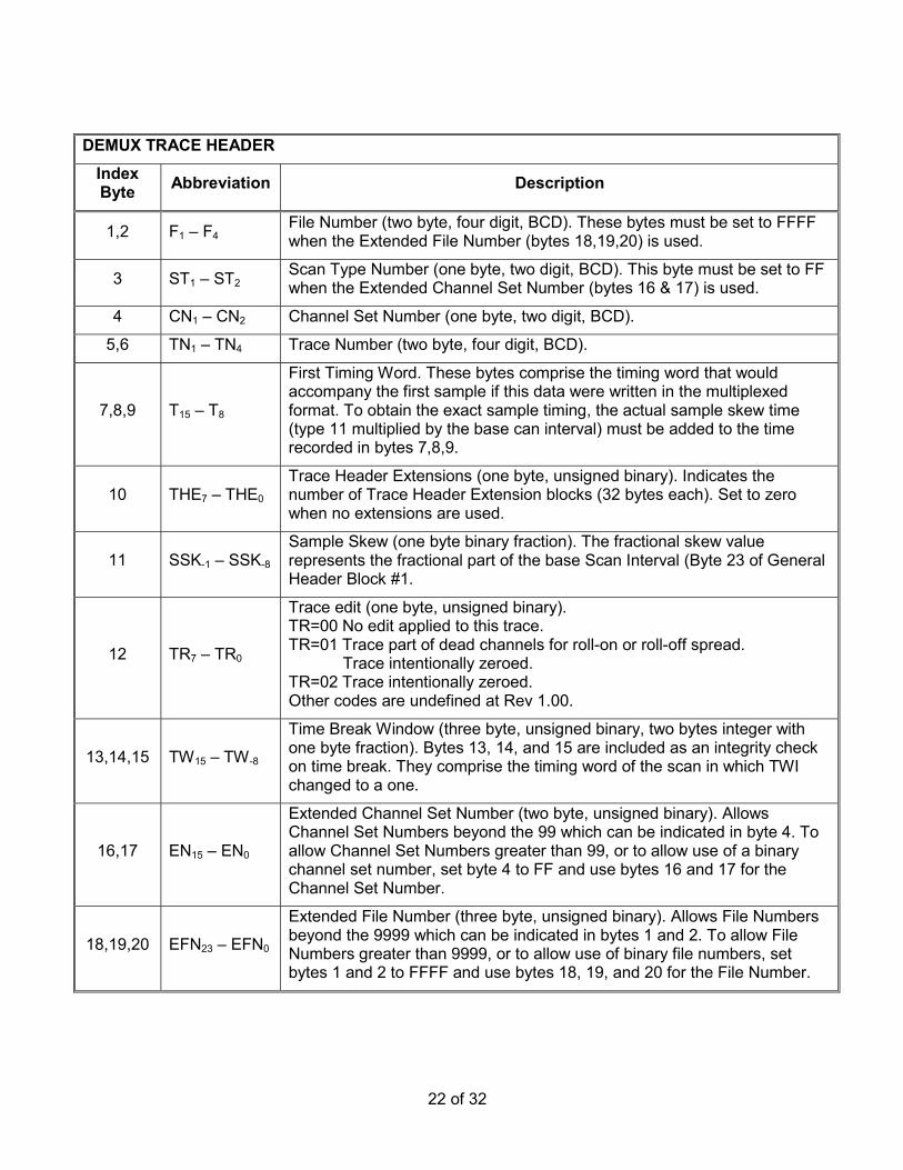
1,2 F1 – F4 File Number (two byte, four digit, BCD). These bytes must be set to FFFF when the Extended File Number (bytes 18,19,20) is used.
3 ST1 – ST2 Scan Type Number (one byte, two digit, BCD). This byte must be set to FF when the Extended Channel Set Number (bytes 16 & 17) is used.
4 CN1 – CN2 Channel Set Number (one byte, two digit, BCD).
5,6 TN1 – TN4 Trace Number (two byte, four digit, BCD).
7,8,9 T15 – T8
First Timing Word. These bytes comprise the timing word that would accompany the first sample if this data were written in the multiplexed format. To obtain the exact sample timing, the actual sample skew time (type 11 multiplied by the base can interval) must be added to the time recorded in bytes 7,8,9.
10 THE7 – THE0 Trace Header Extensions (one byte, unsigned binary). Indicates the number of Trace Header Extension blocks (32 bytes each). Set to zero when no extensions are used.
11 SSK-1 – SSK-8 Sample Skew (one byte binary fraction). The fractional skew value represents the fractional part of the base Scan Interval (Byte 23 of General Header Block #1.
12 TR7 – TR0
Trace edit (one byte, unsigned binary). TR=00 No edit applied to this trace. TR=01 Trace part of dead channels for roll-on or roll-off spread. Trace intentionally zeroed. TR=02 Trace intentionally zeroed. Other codes are undefined at Rev 1.00.
13,14,15 TW15 – TW-8
Time Break Window (three byte, unsigned binary, two bytes integer with one byte fraction). Bytes 13, 14, and 15 are included as an integrity check on time break. They comprise the timing word of the scan in which TWI changed to a one.
16,17 EN15 – EN0
Extended Channel Set Number (two byte, unsigned binary). Allows Channel Set Numbers beyond the 99 which can be indicated in byte 4. To allow Channel Set Numbers greater than 99, or to allow use of a binary channel set number, set byte 4 to FF and use bytes 16 and 17 for the Channel Set Number.
18,19,20 EFN23 – EFN0
Extended File Number (three byte, unsigned binary). Allows File Numbers beyond the 9999 which can be indicated in bytes 1 and 2. To allow File Numbers greater than 9999, or to allow use of binary file numbers, set bytes 1 and 2 to FFFF and use bytes 18, 19, and 20 for the File Number.
X = This field undefined by format and may have any value.
25 of 32
GENERAL TRAILER This type header allows provisions for recording auxiliary seismic system and real-time navigation related data in the trailer. The trailer is optional and typically follows all other recorded data. The addition of the trailer will allow the accumulation of system faults, data QC information, and real-time navigation position and timing information on the same tape, and contiguous with, the shotpoint that it relates to. By recording this data after all of the other data, additional time is provided for collecting the data and transferring it to the recording system. The Trailer blocks take the same general form as the Channel Set Descriptor. Byte 11 uses the "Channel Type Identification" set to 1100 to indicate a Trailer block. Bytes 1 and 2 indicate the number of the General Trailer block, with the first block numbered as 1. All other information in the trailer is optional and may be formatted as desired by the manufacturer/user. The number of General Trailer blocks is indicated in bytes 13 and 14 of General Header Block #2.
Index Byte Abbreviation Description
1,2 GT15 – GT0 General Trailer Number (two bytes unsigned binary). The first block is 1. The last General Trailer block should contain the same number in this field as in bytes 13 and 14 of General Header Block #2.
3 - 10 X These fields are undefined by format. They may have any value.
11 C1 – C0, X Channel Type Identification (one nibble, unsigned binary). Set to 1100 for General Trailers. The second nibble of this byte is undefined and may have any value.
12 - 32 X These fields are undefined by format. They may have any value.
TRACE HEADER EXTENSION Index Byte Abbreviation Description
1,2,3 RLNS, RLN22 – RLN0 Receiver Line Number (three bytes, two's complement, signed binary).
4,5,6 RPNS, RPN22 – RPN0
Receiver Point Number (three bytes, two's complement, signed binary).
7 RPIS, RPI6 – RPI0
Receiver Point Index (one byte, two's complement, signed binary). This index allows several locations for the receiver group in the grid, the original value is 1 and that value is incremented by 1 every time the receiver is moved, even when it is moved back to the previous location).
8,9,10 NBS23 – NBS0 Number of Samples per Trace (three bytes, unsigned binary).
11 - 32 These fields are undefined by format and may have any value.
26 of 32
GENERAL TRAILER Bit 0 1 2 3 4 5 6 7 BCD VALUE MSD 8 4 2 1 8 4 2 1 BINARY VALUE MSB 128 64 32 16 8 4 2 1
12 Redcor Corporation (Obsolete) 7800 Deering Ave. Box 1031 Canoga Park, California 91304
14 Scientific Data Systems (SDS) (Obsolete) 1649 Seventeenth St. Santa Monica, California 90404
13 Sercel (Societe d'Etudes, Recherches Et Constructions Electroniques) 25 X, 44040 Nantes Cedex, France
04 SIE, Inc. 5110 Ashbrook Box 36293 Houston, Texas 77036
15 Halliburton Energy Services formerly Texas Instruments, Inc. 6909 Southwest Freeway Houston, Texas 77074
31 Japex Geoscience Institute Akasaka Twin Towers Bldg. 2; 2-17-22, Akasaka Minato-ku; Tokyo 107, Japan
29 of 32
32 Halliburton Energy Services 6909 Southwest Freeway Houston, Texas 77074
33 Compuseis, Inc. 8920 Business Park Dr, Ste 275, Austin, Texas 78759
34 Syntron, Inc. 17200 Park Row Houston, Texas 77084
35 Syntron Europe Ltd. Birchwood Way
Cotes Park Industrial Estates Somercotes, Alfreton, Dergyshire DE55 4QQ, U.K.
19 Geco-Prakla Transition Zone Product Development (formerly Terra Marine Engineering) 10420 Miller Road, Dallas, Texas 75238
22 Geco-Prakla 42, Rue Saint Dominique; Paris, France
30 of 32
APPENDIX D-HEADER DESCRIPTORS
Abbreviation Header Description AF Channel Set Descriptor ALIAS FILTER FREQUENCY ARY Channel Set Descriptor ARRAY FORMING AS Channel Set Descriptor ALIAS FILTER SLOPE B General Header Blk #1 BYTES PER SCAN (MULTIPLEXED ONLY) BN General Header Btk #2, GENERAL HEADER BLOCK NUMBER General Header BIk #N GENERAL HEADER BLOCK NUMBER C Channel Set Descriptor, CHANNEL TYPE IDENTIFICATION General Trailer CHANNEL TYPE IDENTIFICATION CAB Channel Set Descriptor STREAMER NUMBER CN Demux Trace Header CHANNEL SET NUMBER Channel Set Descriptor CHANNEL SET NUMBER CS General Header BIk #1 CHANNEL SETS PER SCAN TYPE C/S Channel Set Descriptor CHANNELS IN THIS CHANNEL SET DY General Header BIk #1 DAY OF YEAR EC General Header Btk #1 EXTENDED HEADER BLOCK ECS Channel Set Descriptor EXTENDED CHANNEL SET NUMBER ECX General Header Blk #2 EXTENDED HEADER BLOCKS EF General Header BIk #2, EXPANDED FILE NUMBER EFH Channel Set Descriptor EXTENDED HEADER FLAG EFN Demux Trace Header EXTENDED FILE NUMBER EH General Header Blk #2 EXTERNAL HEADER BLOCKS EN Demux Trace Header, EXTENDED CHANNEL SETS AND SCAN TYPE General Header BIk #2 EXTENDED CHANNEL SETS AND SCAN TYPE EX General Header BIk #1 EXTERNAL HEADER LENGTH ERL General Header BIk #2 EXTENDED RECORD LENGTH
31 of 32
Abbreviation Header Description F Demux Trace Header, FILE NUMBER General Header BIk #1 FILE NUMBER GH General Header BIk #1 NUMBER BLOCKS IN GENERAL HEADER GT General Trailer, GENERAL TRAILER NUMBER General Header BIk #2 GENERAL TRAILER NUMBER H General Header BIk #1 HOUR OF DAY I General Header BIk #1 BASE SCAN INTERVAL J Channel Set Descriptor GAIN CONTROL METHOD K General Header BIk #1 GENERAL CONSTANTS LC Channel Set Descriptor LOW CUT FILTER FREQUENCY LS Channel Set Descriptor LOW CUT FILTER SLOPE M General Header BIk #1 MANUFACTURER'S CODE AND SERIAL NUMBER MI General Header BIk #1 MINUTE OF HOUR MP Channel Set Descriptor DESCALING EXPONENT NBS Trace Header Extension NUMBER OF SAMPLES PER TRACE NT Channel Set Descriptor NOTCH FILTER FREQUENCY P General Header BIk #1 POLARITY PA General Header BIk #N PHASE ANGLE PC General Header BIk #N PHASE CONTROL R General Header BIk #1 RECORD LENGTH REV General Header BIk #2 SEG-D REVISION NUMBER RLN Trace Header Extension RECEIVER LINE NUMBER
32 of 32
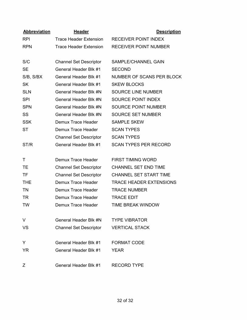
Abbreviation Header Description RPI Trace Header Extension RECEIVER POINT INDEX RPN Trace Header Extension RECEIVER POINT NUMBER S/C Channel Set Descriptor SAMPLE/CHANNEL GAIN SE General Header BIk #1 SECOND S/B, S/BX General Header BIk #1 NUMBER OF SCANS PER BLOCK SK General Header BIk #1 SKEW BLOCKS SLN General Header BIk #N SOURCE LINE NUMBER SPI General Header BIk #N SOURCE POINT INDEX SPN General Header BIk #N SOURCE POINT NUMBER SS General Header BIk #N SOURCE SET NUMBER SSK Demux Trace Header SAMPLE SKEW ST Demux Trace Header SCAN TYPES Channel Set Descriptor SCAN TYPES ST/R General Header BIk #1 SCAN TYPES PER RECORD T Demux Trace Header FIRST TIMING WORD TE Channel Set Descriptor CHANNEL SET END TIME TF Channel Set Descriptor CHANNEL SET START TIME THE Demux Trace Header TRACE HEADER EXTENSIONS TN Demux Trace Header TRACE NUMBER TR Demux Trace Header TRACE EDIT TW Demux Trace Header TIME BREAK WINDOW V General Header BIk #N TYPE VIBRATOR VS Channel Set Descriptor VERTICAL STACK Y General Header BIk #1 FORMAT CODE YR General Header BIk #1 YEAR Z General Header BIk #1 RECORD TYPE