1 Segmentation and Enhancement of Latent Fingerprints: A Coarse to Fine Ridge Structure Dictionary Kai Cao, Eryun Liu, Member, IEEE and Anil K. Jain, Fellow, IEEE Abstract—Latent fingerprint matching has played a critical role in identifying suspects and criminals. However, compared to rolled and plain fingerprint matching, latent identification accuracy is significantly lower due to complex background noise, poor ridge quality and overlapping structured noise in latent images. Accordingly, manual markup of various features (e.g., region of interest, singular points and minutiae) is typically necessary to extract reliable features from latents. To reduce this markup cost and to improve the consistency in feature markup, fully automatic and highly accurate (“lights-out” capability) latent matching algorithms are needed. In this paper, a dictionary-based approach is proposed for automatic latent segmentation and enhancement towards the goal of achieving “lights-out” latent identification systems. Given a latent fingerprint image, a total variation (TV) decomposition model with L 1 fidelity regularization is used to remove piecewise-smooth background noise. The texture component image obtained from the decomposition of latent image is divided into overlapping patches. Ridge structure dictionary, which is learnt from a set of high quality ridge patches, is then used to restore ridge structure in these latent patches. The ridge quality of a patch, which is used for latent segmentation, is defined as the structural similarity between the patch and its reconstruction. Orientation and frequency fields, which are used for latent enhancement, are then extracted from the reconstructed patch. To balance robustness and accuracy, a coarse to fine strategy is proposed. Experimental results on two latent fingerprint databases (i.e., NIST SD27 and WVU DB) show that the proposed algorithm outperforms the state-of-the-art segmentation and enhancement algorithms and boosts the performance of a state-of-the-art commercial latent matcher. Index Terms—Latent fingerprint, image decomposition, segmentation, ridge enhancement, sparse coding, dictionary learning. ✦ 1 I NTRODUCTION L ATENT fingerprints (or simply latents or finger marks) refer to fingerprints lifted from the sur- faces of objects inadvertently touched or handled by a person typically at crime scenes. Compared to rolled and plain fingerprints (or exemplar finger- prints), which are acquired in an attended mode, latents are typically of poor quality in terms of ridge structure, containing background noise and non-linear distortion (see Fig. 1). Due to these factors, the la- tent identification (i.e., latent to exemplar matching) accuracy is much lower than that of exemplar finger- prints (exemplar to exemplar matching). As an exam- ple, in NIST evaluations, while the best performing Automated Fingerprint Identification System (AFIS) achieved a rank-1 identification rate of 99.4% on a background database of 10,000 plain fingerprints [1], • Kai Cao and Eryun Liu are with the Dept. of Computer Science and Engineering, Michigan State University, East Lansing, MI 48824 U.S.A. They are also affiliated with the School of Life Sciences and Technology, Xidian University, Xi’an, Shaanxi 710126, China. E-mail: {kaicao,liueryun}@cse.msu.edu • Anil K. Jain is with the Dept. of Computer Science and Engineering, Michigan State University, 3115 Engineering Building, East Lansing, MI, U.S.A. He is also affiliated with the Department of Brain and Cognitive Engineering, Korea University, Seoul 136-713, Republic of Korea. E-mail: [email protected]Fig. 1: Three types of fingerprint images. (a) rolled fingerprint, (b) plain fingerprint, (c) latent fingerprint with foreground (friction ridge pattern) highlighted by red outline. Notice the presence of different types of noise and distortion in (c). the best performing commercial latent matcher could only achieve a rank-1 identification rate of 63.4% in searching 1,114 latents against a background database containing 100,000 exemplar prints [2]. Fig. 2 shows examples of rolled to rolled fingerprint matching and latent to rolled fingerprint matching. In these exam- ples, features in the rolled fingerprints are extracted automatically by an AFIS, but features in the latent image are manually marked. One of the challenging problems in latent identifi- cation is how to automatically extract reliable features in latents, especially latents with poor quality. Given the difficulty of automatic feature extraction, a manual
Transcript
1
Segmentation and Enhancement of LatentFingerprints: A Coarse to Fine Ridge
Structure DictionaryKai Cao, Eryun Liu, Member, IEEE and Anil K. Jain, Fellow, IEEE
Abstract—Latent fingerprint matching has played a critical role in identifying suspects and criminals. However, compared torolled and plain fingerprint matching, latent identification accuracy is significantly lower due to complex background noise,poor ridge quality and overlapping structured noise in latent images. Accordingly, manual markup of various features (e.g.,region of interest, singular points and minutiae) is typically necessary to extract reliable features from latents. To reduce thismarkup cost and to improve the consistency in feature markup, fully automatic and highly accurate (“lights-out” capability) latentmatching algorithms are needed. In this paper, a dictionary-based approach is proposed for automatic latent segmentation andenhancement towards the goal of achieving “lights-out” latent identification systems. Given a latent fingerprint image, a totalvariation (TV) decomposition model with L1 fidelity regularization is used to remove piecewise-smooth background noise. Thetexture component image obtained from the decomposition of latent image is divided into overlapping patches. Ridge structuredictionary, which is learnt from a set of high quality ridge patches, is then used to restore ridge structure in these latent patches.The ridge quality of a patch, which is used for latent segmentation, is defined as the structural similarity between the patchand its reconstruction. Orientation and frequency fields, which are used for latent enhancement, are then extracted from thereconstructed patch. To balance robustness and accuracy, a coarse to fine strategy is proposed. Experimental results on twolatent fingerprint databases (i.e., NIST SD27 and WVU DB) show that the proposed algorithm outperforms the state-of-the-artsegmentation and enhancement algorithms and boosts the performance of a state-of-the-art commercial latent matcher.
LATENT fingerprints (or simply latents or fingermarks) refer to fingerprints lifted from the sur-
faces of objects inadvertently touched or handledby a person typically at crime scenes. Comparedto rolled and plain fingerprints (or exemplar finger-prints), which are acquired in an attended mode,latents are typically of poor quality in terms of ridgestructure, containing background noise and non-lineardistortion (see Fig. 1). Due to these factors, the la-tent identification (i.e., latent to exemplar matching)accuracy is much lower than that of exemplar finger-prints (exemplar to exemplar matching). As an exam-ple, in NIST evaluations, while the best performingAutomated Fingerprint Identification System (AFIS)achieved a rank-1 identification rate of 99.4% on abackground database of 10,000 plain fingerprints [1],
• Kai Cao and Eryun Liu are with the Dept. of Computer Science andEngineering, Michigan State University, East Lansing, MI 48824U.S.A. They are also affiliated with the School of Life Sciences andTechnology, Xidian University, Xi’an, Shaanxi 710126, China.E-mail: {kaicao,liueryun}@cse.msu.edu
• Anil K. Jain is with the Dept. of Computer Science and Engineering,Michigan State University, 3115 Engineering Building, East Lansing,MI, U.S.A. He is also affiliated with the Department of Brain andCognitive Engineering, Korea University, Seoul 136-713, Republic ofKorea.E-mail: [email protected]
Fig. 1: Three types of fingerprint images. (a) rolledfingerprint, (b) plain fingerprint, (c) latent fingerprintwith foreground (friction ridge pattern) highlightedby red outline. Notice the presence of different typesof noise and distortion in (c).
the best performing commercial latent matcher couldonly achieve a rank-1 identification rate of 63.4% insearching 1,114 latents against a background databasecontaining 100,000 exemplar prints [2]. Fig. 2 showsexamples of rolled to rolled fingerprint matching andlatent to rolled fingerprint matching. In these exam-ples, features in the rolled fingerprints are extractedautomatically by an AFIS, but features in the latentimage are manually marked.
One of the challenging problems in latent identifi-cation is how to automatically extract reliable featuresin latents, especially latents with poor quality. Giventhe difficulty of automatic feature extraction, a manual
2
markup of various features in latents, such as regionof interest (ROI), singular points and minutiae, is thecurrent practice. However, this human factor issue inlatent examination has raised some concerns relatedto repeatability and reliability [3],[4]. For example,markup of a specific feature type (e.g., minutiae)by different latent examiners or even by the sameexaminer at different times may not give the sameresults. A study conducted by NIST showed that theaccuracy of a latent matcher is highly affected by theprecision of latent examiner markup, especially whenthe latent image itself is not available to the matche[2]. One of the factors that affects human markupperformance is that latent examiners often work un-der extreme time pressure due to heavy case work.Studies have shown that when the comparison timeis limited, latent examiners are more likely to make aninconclusive matching decision between a latent andits mated rolled print [5]. One of the most infamouscases involving mistaken identity based on latentmatching is the Brandon Mayfield case [6]. Othercases of mistaken identifications have been reportedby the Innocence project [7]. One of the prioritiesof FBI’s Next Generation Identification (NGI) is tosupport the development of a lights-out1 capabilityfor latent identification [9]. An essential componentof this lights-out capability is to develop a fullyautomatic latent feature extraction module. This ishighly desirable to (i) increase the throughput of latentmatching systems, (ii) improve repeatability of latentfeature extraction and, (iii) increase the compatibilitybetween features extracted in the latents and featuresextracted in the reference prints by an AFIS [10].
An AFIS, whether for rolled/plain print matchingor latent matching, typically contains a number ofmodules, including region of interest (ROI) segmen-tation (separating friction ridge from background),enhancement, feature extraction, and matching. Seg-mentation, especially for latents, is critical to avoidextraction of features (e.g., minutiae) in the noisybackground [11]. Enhancing ridge and valley struc-tures and removing noise in the foreground region areessential to extract accurate features. The Gabor fil-ter based fingerprint enhancement[12] can adaptivelyimprove the clarity of ridge and valley structures; thefilters are tuned based on the local ridge orientationand frequency. Therefore, for latent enhancement itis essential to get good estimates of ridge orientationand frequency fields.
There is a rich body of literature on exemplar fin-gerprint segmentation [12], [13], [14], [15], orientationfield estimation [12], [16], [15], [17], [18] and frequencyfield estimation [19], [15]. But these approaches do notwork well on latent fingerprints. Compared with ex-
1. Lights-out identification refers to an AFIS requiring minimalor no human assistance in which a query fingerprint image ispresented as input, and the output consists of a short candidatelist [8].
Fig. 2: Examples of (a) rolled to rolled fingerprintmatching and (b) latent to rolled fingerprint matching.In these examples, features in the rolled fingerprintswere extracted automatically by an AFIS, but features(minutiae, region of interest and singular points) inthe latent were manually marked.
emplar fingerprints, there are two types of difficultiesin latent segmentation and enhancement: i) presenceof structured noise, such as lines, markings, charactersand speckles. Some of the structured noise may evenoverlap with the ridge pattern (see Fig. 1 (c)). Thisstructured noise breaks the ridge flow pattern in thefingerprint and affects the subsequent processing; ii)poor quality of ridge structure in the foreground area.The low clarity of ridge structure makes it difficult toestimate orientation and frequency fields in latents.
Some approaches have been proposed that specif-ically address the problem of latent fingerprint seg-mentation [20], [21], [26], [22], [25] and enhancement[23], [24], [10]. In [20], the orientation and frequency inan image block (typically 8×8 pixels) were estimatedusing a local gray intensity projection method; thedistance between center-of-transient points was usedfor segmentation. However, no performance evalua-tion was reported. Short et al. [21] generated an idealridge model template and used the cross-correlationbetween a local block and the generated templateto define the local fingerprint quality. However, thisapproach is not able to account for minutiae, ridgecurvature and variance in ridge frequency. Zhang et al.[26] proposed an adaptive total variation (TV) decom-position model for latent fingerprint segmentation.They further proposed an adaptive directional totalvariation (ADTV) model by incorporating orientationfield and local orientation coherence [25]. However,the orientation field and its local coherency were
3
TABLE 1: A comparison of latent segmentation and enhancement algorithms proposed in the literatureAlgorithm Objective Approach Performance evaluation Databasea Comments
Karimi et al.[20]
Segmentation &enhancement
Local gray intensityprojection Not reported Latents: Two latents
from NIST SD27 Not robust to noise
Short et al.[21] Segmentation
Correlation withideal ridgetemplates
EER of 33.8% Latents: NIST SD27 Relies on templategeneration
Choi et al.[22] Segmentation
Orientationtensor and ridgefrequency
Rank-1 identification accu-racy of 16.28% and 35.19%on NIST SD27 and WVUdatabases, respectively, bya COTS tenprint matcher
Latents: NISTSD27 & WVU DBBackground: 31,997rolled prints
Orientation and fre-quency maps areused separately
Yoon et al.[23] Enhancement
Polynomial modeland zero-polemodel
Rank-1 identification accu-racy of 35% by VeriFingerbSDK 4.2
Rank-1 identification accu-racy of 26% by VeriFingerSDK 6.2
Latents: NIST SD27Background: 27,258rolled prints
Requires ROI anduses fixed ridge fre-quency
Zhang et al.[25]
Segmentation &enhancement
Adaptivedirectional totalvariation model
Rank-1 identification accu-racy of less than 2% by Ver-iFinger SDK 6.6
Latents: NISTSD27 (1,000ppi)Background: 27,258rolled prints
Relies on orienta-tion field and orien-tation coherence es-timation
Proposedalgorithm
Segmentation &enhancement
Image decomposi-tion; ridge structurecoarse to fine dictio-nary
Rank-1 identification accu-racy of 61.24% and 70.16%on NIST SD27 and WVUdatabases, respectively, bya COTS latent matcher
Latents: NISTSD27 & WVU DBBackground: 31,997rolled prints
Fully automatic; nomanual markup re-quired
a The NIST SD27 contains 258 latent fingerprints and their rolled mates and the WVU DB contains 449 latent fingerprints and theirrolled mates (4,290 additional rolled prints are also provided). The background database includes 258 rolled fingerprint from NISTSD27, 4,739 rolled fingerprints from WVU DB and 27,000 rolled fingerprints (including the 449 mated prints) from NIST SD14.
b Verifinger is a tenprint matcher.
computed from the gray scale latent images whichare not reliable due to the low quality of frictionridge structure. Choi et al. [22] used the orientationtensor and Fourier response in valid frequency re-gions to segment latent fingerprints separately; anintersection of the resulting segmented regions wasused to localize the latent fingerprint (foreground)region. However, they did not utilize the correlationbetween ridge orientation and ridge frequency.
In the latent enhancement approaches reported inthe literature, manual markup of ROI and/or singularpoints are typically needed as input [23], [24], [10]. In[23], the orientation field was obtained by fitting apolynomial model to the coarse orientation field. Theauthors improved this approach by using short-timeFourier transform (STFT) and randomized RANSAC[24], but it still required manual markup of ROI andsingular points. Feng et al. proposed a dictionary oforientation patches to estimate the orientation fieldin the manually marked ROI [10]. The orientationfield estimation was posed as an energy minimiza-tion problem, which consists of the (i) similarity be-tween orientation patches and orientation dictionaryelements, and (ii) compatibility between neighboringorientation dictionary elements. However, all theseapproaches used a fixed ridge frequency to tuneGabor filters for latent enhancement. In [25], image
decomposition using the ADTV model was used toenhance the ridge quality. Table 1 compares variouslatent segmentation and enhancement algorithms pro-posed in the literature.
To address the two main difficulties in latent finger-print matching, namely presence of structured noiseand poor quality of ridge structure, we propose adictionary-based segmentation and enhancement oflatent fingerprint. To remove the structured noise, thetotal-variation model with L1 fidelity regularization[27] is used to decompose a latent into a texture partand a cartoon part2. The relative reduction rate of localtotal variation (LTV ) is used as an index of local oscil-latory pattern and a nonlinear decomposition methodwas proposed for the decomposition. The cartoonpart with piecewise-smooth characteristics containingstructured noise is discarded. To define ridge qualityand estimate orientation and frequency fields, a ridgestructure dictionary is proposed. A dictionary is aset of words (or vectors) used to sparsely and lin-early represent signals of the same dimension, namelysparse coding. Dictionary and sparse coding havebeen successfully applied to a number of signal pro-cessing tasks, such as image denoising [28], [29], clas-
2. Cartoon image is a piecewise-smooth image whose discontinu-ity set includes in a union of curves whose overall length is finite[27].
4
Fig. 3: An example of latent segmentation and enhancement by the proposed algorithm. (a) A latent fingerprintimage (U286 from NIST SD27); (b) fully automatic segmentation of (a) by the proposed algorithm; (c)enhancement of (b) by the proposed algorithm; (d) the true mate (rolled print) of (a) with the segmentationboundary in (b) outlined on the mate. By feeding the original latent in (a), the segmented latent in (b) andthe enhanced latent in (c) into a commercial off-the-shelf (COTS) latent matcher (with a background databaseof 31,997 reference prints), the mated print is retrieved at ranks 4,152, 26 and 2, respectively. The contrast ofimages in (a) and (b) has been enhanced for better visual quality.
sification [30], [31] and face recognition [32], [33]. Fenget al. [10] proposed a dictionary of orientation patchesfor orientation field estimation in latent fingerprints.However, their dictionary cannot be successfully usedfor latent segmentation and frequency field extractionsince ridge information is ignored. In this paper, theridge structure dictionaries are learnt from a set ofhigh quality fingerprint patches from rolled finger-prints and then used to recover the ridge structurefrom noisy latent patches. The ridge quality of apatch is defined as the structural similarity betweenthe original patch and its reconstruction. Orientationand frequency fields of a patch are estimated fromits reconstruction and used to tune the Gabor filtersfor latent enhancement. Fig. 3 shows an examplelatent fingerprint where the proposed segmentationand enhancement improves the latent identificationperformance (retrieval rank) of a COTS latent matcher.The main contributions of this paper are as follows:
1) Ridge structure dictionary is proposed for latentsegmentation and enhancement. The dictionaryis learnt from hight quality fingerprint patches.
2) The ridge quality of a patch is defined as thestructural similarity between the patch and itsreconstruction from the learnt ridge structuredictionary. Orientation and frequency fields ofa patch are estimated from its reconstruction.
3) To balance robustness and accuracy, a coarse tofine strategy is proposed which uses dictionariesat two levels of resolution (64× 64 and 32× 32).
4) The proposed segmentation and enhancementalgorithms outperform published algorithmsand can also significantly boost the performanceof a state-of-the-art commercial latent matcheron two latent database (NIST SD27 and WVUDB).
The rest of the paper is organized as follows. Thedetails of the proposed algorithm are presented in
section 2. Experimental results are reported in section3. Finally, conclusions and future research directionsare reported in section 4.
2 PROPOSED ALGORITHM2.1 Algorithm OverviewThe proposed algorithm consists of an off-line dictio-nary learning stage and on-line stage for segmentationand enhancement (see Fig. 4). In the off-line stage,two types of dictionaries are learnt: i) a coarse-leveldictionary with patch size of 64 × 64 pixels, and ii)16 fine-level dictionaries with patch size of 32 × 32pixels; these 16 fine level dictionaries correspond to16 different ridge orientations. The 64× 64 patch sizedictionary is used for coarse estimation of ridge qual-ity map, orientation and frequency fields, while the16 orientation specific 32 × 32 patch size dictionariesare used for fine estimation of ridge quality map,and orientation and frequency fields computation.The patch size in fine-level dictionaries is chosen tobe 32 × 32 pixels since it covers about two ridgesand valleys in 500 ppi fingerprints and is robust tostructured noise. The patch size in the coarse-leveldictionary (64×64 pixels) is twice the size of the fine-level dictionary.
Given the dictionaries, on-line latent segmentationand enhancement consists of the following steps:
1) Latent decomposition: Input latent is decom-posed into cartoon and texture images via localtotal variations [27]; the cartoon image is dis-carded.
2) Coarse level estimation of quality map and ori-entation and frequency fields: The texture im-age is divided into overlapping patches of size64 × 64 pixels (P c
L). Each patch has 64 × 48 or48 × 64 overlapping pixels with each of its fourconnected neighboring blocks. For each patch
5
Fig. 4: Overview of the proposed latent segmentation and enhancement algorithm. The off-line dictionarylearning and on-line latent segmentation and enhancement stages are separated by dashed lines.
p ∈ P cL, its sparse representation and recon-
structed patch p̂ using the coarse level dictionaryare obtained by orthogonal matching pursuit[34]. The structural similarity [35] between p andp̂ is defined as the coarse quality of the patch.Since the reconstructed patch p̂ generally hasa clear ridge pattern, the ridge orientation andfrequency in patch p can be replaced with thefeatures in the reconstructed patch p̂. In regionswhere patches overlap, the coarse quality, coarseorientation and frequency fields are obtained bythe covering patches.
3) Fine level estimation of quality map and ori-entation and frequency fields: The texture im-age is divided into overlapping patches of size32 × 32 pixels (P f
L ). Each patch has 32 × 16 or16 × 32 overlapping pixels with each of its fourconnected neighboring blocks. For each patchp ∈ P f
L , the coarse ridge orientation value is firstused to index the corresponding fine level dictio-nary. The fine estimation of ridge quality map,orientation and frequency fields are computedas coarse estimation in step 2).
4) Segmentation and enhancement: The coarsequality map and fine quality map are combinedfor latent segmentation. In the foreground oftexture image, Gabor filtering based on the ori-entation and frequency fields obtained in 2) and3) is applied for latent enhancement.
2.2 Dictionary LearningFeng et al. [10] were the first to propose the use ofdictionary for fingerprint orientation field estimation.However, their dictionary was based on orientationpatches and they ignored the ridge structure infor-mation. This is the main reason their method in[10] was not very successful for segmentation andfrequency field estimation. In this section, we presentthe proposed ridge structure dictionary learning.
2.2.1 Training Set SelectionIn order to construct reliable and robust dictionaries, alarge number of high quality fingerprint patches fromrolled image in NIST SD4 [36] are selected. The imagepatches are selected as follows:
6
Fig. 5: A subset of elements in the coarse-level dictio-nary (patch size: 64 × 64 pixels). The total number ofdictionary elements is 1,024.
Fig. 6: A subset of elements in the 16 orientationspecific dictionaries (patch size: 32 × 32 pixels). Theith row corresponds to the ith orientation specific dic-tionary in the orientation range
[(i − 1) × π
16 , i × π16
),
i=1,...,16. The total number of elements in each orien-tation specific dictionary is 64.
1) High quality fingerprint selection: NIST Finger-print Image Quality (NFIQ) [37] is used to select500 fingerprints of high quality3 (i.e., NFIQ < 3)in NIST SD4.
2) High quality patch selection: MINDTCT [38] (inNIST Fingerprint Image Software (NFIS)) is usedto estimate the orientation field and a block-wiseridge quality map of the fingerprints selected in1). The ridge quality map provides one of the 5quality levels for each block (with 4 being the
3. NFIQ ranges from 1 to 5, with 1 indicating the highest qualityand 5 indicating the lowest quality fingerprint.
highest quality and 0 being the lowest quality).For the coarse-level dictionary, a set of imagepatches, P c, of size 64 × 64 pixels are selectedby sliding a window over the fingerprint im-age with a step size of 8 pixels; if the averagequality value of an image patch is larger thana predefined threshold T (T is set to 3.75), thepatch is included in the training set. For theorientation specific dictionaries, 16 sets of finger-print patches P f
i , i = 1, · · · , 16, are constructedaccording to ridge orientation. For P f
i , a 32× 32window is slided over the fingerprint image;a patch is selected if it satisfies the followingtwo conditions: i) average quality value of thepatch is larger than T , and ii) average ridgeorientation of the patch is within the range[(i − 1) × π
16 , i × π16
).
3) Vector normalization: Each patch p in the train-ing set is normalized by Eq. (1) and convertedto a vector by concatenating the rows.
p̃ = (p − μp)/σp, (1)
where μp is the mean intensity and σp is thestandard deviation of patch p.
Let P c = {pcj}Nc
j=1 be the training set for thecoarse-level dictionary, where N c denotes the num-
ber of training patches in P c, and P fi = {pf
i,j}Nfi
j=1,i = 1, · · · , 16, be the training sets for the 16 fine-level dictionaries, where Nf
i denotes the number oftraining patches for the ith dictionary specified byridge orientation. To balance efficiency and accuracy,we randomly select 80,000 patches from P c and 10,000patches from each P f
i , respectively, for dictionarylearning.
2.2.2 Dictionary LearningWithout loss of generality, for a training set P ={pj}N
j=1, the goal of dictionary learning is to constructa dictionary D of size NP ×ND that provides the bestsparse representation for each patch in P , where NP
is the dimensionality of the patches in P , and ND isthe number of elements in the dictionary D. A typicalobjective function for dictionary learning is
minD,Γ
||P − DΓ||2F s.t. ∀j, ||γj ||0 ≤ T0, (2)
where γj is the jth column of matrix Γ of size ND×N ,||·||0 is the l0 norm that counts the number of nonzeroentries in the representation, T0 is a predeterminednumber of nonzero entries and || · ||F denotes theFrobenius norm. One of the effective algorithms fordictionary learning is K-SVD [39], which minimizesthe objective function in Eq. (2) by iterating the fol-lowing two stages.
• Sparse coding stage: Obtain the representationcoefficient vector γj for each patch pj in P by
7
solving the following optimization problem un-der a fixed dictionary D:
(3)• Dictionary update stage: This stage reduces the
objective function in Eq. (2) by updating onecolumn of the dictionary D at a time via singularvalue decomposition (SVD) while fixing all othercolumns of D.
The initial dictionary D is constructed using the dis-crete cosine transform (DCT) basis. Each dictionaryelement is normalized by Eq. (1) after learning.
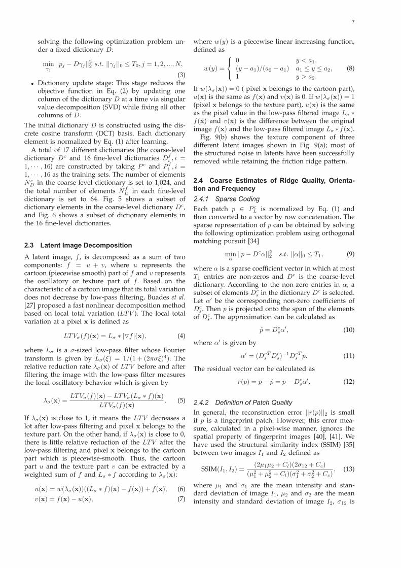
A total of 17 different dictionaries (the coarse-leveldictionary Dc and 16 fine-level dictionaries Df
i , i =1, · · · , 16) are constructed by taking P c and P f
i , i =1, · · · , 16 as the training sets. The number of elementsN c
D in the coarse-level dictionary is set to 1,024, andthe total number of elements Nf
D in each fine-leveldictionary is set to 64. Fig. 5 shows a subset ofdictionary elements in the coarse-level dictionary Dc,and Fig. 6 shows a subset of dictionary elements inthe 16 fine-level dictionaries.
2.3 Latent Image DecompositionA latent image, f , is decomposed as a sum of twocomponents: f = u + v, where u represents thecartoon (piecewise smooth) part of f and v representsthe oscillatory or texture part of f . Based on thecharacteristic of a cartoon image that its total variationdoes not decrease by low-pass filtering, Buades et al.[27] proposed a fast nonlinear decomposition methodbased on local total variation (LTV ). The local totalvariation at a pixel x is defined as
LTVσ(f)(x) = Lσ ∗ |�f |(x), (4)
where Lσ is a σ-sized low-pass filter whose Fouriertransform is given by L̂σ(ξ) = 1/(1 + (2πσξ)4). Therelative reduction rate λσ(x) of LTV before and afterfiltering the image with the low-pass filter measuresthe local oscillatory behavior which is given by
λσ(x) =LTVσ(f)(x) − LTVσ(Lσ ∗ f)(x)
LTVσ(f)(x). (5)
If λσ(x) is close to 1, it means the LTV decreases alot after low-pass filtering and pixel x belongs to thetexture part. On the other hand, if λσ(x) is close to 0,there is little relative reduction of the LTV after thelow-pass filtering and pixel x belongs to the cartoonpart which is piecewise-smooth. Thus, the cartoonpart u and the texture part v can be extracted by aweighted sum of f and Lσ ∗ f according to λσ(x):
where w(y) is a piecewise linear increasing function,defined as
w(y) =
⎧⎨⎩
0 y < a1,(y − a1)/(a2 − a1) a1 ≤ y ≤ a2,1 y > a2.
(8)
If w(λσ(x)) = 0 ( pixel x belongs to the cartoon part),u(x) is the same as f(x) and v(x) is 0. If w(λσ(x)) = 1(pixel x belongs to the texture part), u(x) is the sameas the pixel value in the low-pass filtered image Lσ ∗f(x) and v(x) is the difference between the originalimage f(x) and the low-pass filtered image Lσ ∗f(x).
Fig. 9(b) shows the texture component of threedifferent latent images shown in Fig. 9(a); most ofthe structured noise in latents have been successfullyremoved while retaining the friction ridge pattern.
2.4 Coarse Estimates of Ridge Quality, Orienta-tion and Frequency2.4.1 Sparse CodingEach patch p ∈ P c
L is normalized by Eq. (1) andthen converted to a vector by row concatenation. Thesparse representation of p can be obtained by solvingthe following optimization problem using orthogonalmatching pursuit [34]
minα
||p − Dcα||22 s.t. ||α||0 ≤ T1, (9)
where α is a sparse coefficient vector in which at mostT1 entries are non-zeros and Dc is the coarse-leveldictionary. According to the non-zero entries in α, asubset of elements Dc
s in the dictionary Dc is selected.Let α′ be the corresponding non-zero coefficients ofDc
s. Then p is projected onto the span of the elementsof Dc
s. The approximation can be calculated as
p̂ = Dcsα
′, (10)
where α′ is given by
α′ = (DcsT Dc
s)−1Dc
sT p. (11)
The residual vector can be calculated as
r(p) = p − p̂ = p − Dcsα
′. (12)
2.4.2 Definition of Patch QualityIn general, the reconstruction error ||r(p)||2 is smallif p is a fingerprint patch. However, this error mea-sure, calculated in a pixel-wise manner, ignores thespatial property of fingerprint images [40], [41]. Wehave used the structural similarity index (SSIM) [35]between two images I1 and I2 defined as
SSIM(I1, I2) =(2μ1μ2 + Cl)(2σ12 + Cc)
(μ21 + μ2
2 + Cl)(σ21 + σ2
2 + Cc), (13)
where μ1 and σ1 are the mean intensity and stan-dard deviation of image I1, μ2 and σ2 are the meanintensity and standard deviation of image I2, σ12 is
8
Fig. 7: Patch reconstruction results with different val-ues of parameter T1. (a) Texture component of highquality fingerprint patch (top), low quality fingerprintpatch (middle), and non-fingerprint patch (bottom),(b), (c), (d) and (e) are the reconstruction results whenT1 = 1 , T1 = 2, T1 = 3 and T1 = 4, respectively.Recall that T1 determines the number of dictionaryelements used to reconstruct the original image. TheSSIM indices between the given patch (column (a))and the reconstructed patch with different value ofT1 are shown.
Fig. 8: Orientation fields of the patches correspondingto Fig. 7.
the covariance between I1 and I2, and Cl and Cc areparameters to reduce the instability in computation.
Fig. 7 compares the reconstruction results and SSIMindices for two fingerprint patches (top and middlerows) and one non-fingerprint patch (bottom row)when T1 is varied from 1 to 4. We observe thatthe high quality fingerprint patch has large SSIMvalues between patch p and its reconstruction p̂, whilethe non-fingerprint patch results in very small SSIMvalues. The quality Qp of the patch p is defined as
Qp = SSIM(p, p̂). (14)
2.4.3 Ridge Quality Map, Orientation field and Fre-quency Field EstimationThe reconstructed patch p̂ is divided into non-overlapping 16 × 16 blocks, as used in [12] and [10].
For each block, its orientation and frequency are ob-tained based on [12], resulting in reconstructed patchorientation field θp̂ (see Fig. 8) and frequency field fp̂.The reconstructed orientation field θp̂ and frequencyfp̂ of patch p̂ are used as the estimates of orientationfield θp and frequency field fp of the patch p inthe latent image. For a region covered by multiplepatches, its quality, orientation and frequency aredefined as follows. The latent image is divided intonon-overlapping 16×16 blocks. For each block b in thelatent, let {qi, θi, fi} be the ridge quality, orientationand frequency of the ith patch covering the block b.The coarse estimates of ridge quality Qc
b, orientationθc
b and frequency fcb are given as:
Qcb =
1nb
nb∑i=1
qi, (15)
θcb =
12
tan−1
(nb∑i=1
qi sin 2θi,
nb∑i=1
qi cos 2θi
),(16)
fcb =
1∑ns
i=1 qi
ns∑i=1
qifi, (17)
where nb is the number of patches covering the blockb.
2.4.4 Sparsity Control
The parameter T1 in Eq. (9) is used to control thedegree of sparsity in sparse coding. Figs. 7 and 8 showthat while large values of T1 lead to a better approx-imation of the input patch, it introduces unwantednoise. In particular, a single dictionary element isenough to recover level 1 features (orientation and fre-quency). For T1 = 1, the coefficient vector α′ becomesa scalar and the computation of α′ is simplified to:
α′ =1
Np − 1Dc
sT p, (18)
where Np is the number of pixels in patch p. Eq. (18)gives an efficient solution since there is no need toperform matrix inversion (see Eq. (11)). As the patchp is normalized to have the mean of 0 and standarddeviation of 1, the SSIM index computation in Eq. (13)can be simplified to
SSIM(p, p̂) =2α′2 + Cc
1 + α′2 + Cc. (19)
It should be noted that when T1 = 1, the re-constructed patch is an element selected from thedictionary Dc. Thus, the orientation and frequencyfields of the dictionary elements can be pre-calculatedin the off-line stage, which can greatly speed up theorientation and frequency fields estimation. For thesereasons, T1 is set to 1. Fig. 9(c) shows some examplesof coarse quality maps under T1 = 1.
9
Fig. 9: Illustration of latent fingerprint segmentation. (a) Gray scale latent images, (b) extracted texturecomponent images, (c) coarse quality maps, (d) fine quality maps, (e) segmentation results. The top, middleand bottom latent fingerprints in column (a) are of good, bad and ugly quality as defined in NIST SD27,respectively. The contrast of the middle and bottom latent fingerprints has been enhanced to get better visualquality.
2.5 Fine Estimates of Ridge Quality, Orientationand Frequency
The coarse-level dictionary while robust to local noise,does not enable us to extract detailed ridge infor-mation. Small patch size dictionaries enable us tocompute the fine quality map and calculate the fineorientation and frequency fields:
1) All patches in P fL are normalized by Eq. (1) with
mean of zero and standard deviation of one.2) For each patch p ∈ P f
L , a dominant orientation θis obtained by averaging the coarse orientationsof the blocks covered by patch p. Then, thecorresponding orientation specific dictionary Df
k
is selected for patch p, where k = � 16×θπ � and �·�
is the ceiling operator.3) The reconstructed patch p̂ is obtained by solving
the optimization problem in Eq. (9) with dictio-nary Df
k .4) The quality of patch p is determined by the
structural similarity between p and p̂ (Eq. (19)).5) The block wise orientation and frequency fields
of patch p are computed from p̂ by the methodin [12].
6) For each 16 × 16 block b in the latent, the finequality Qf
b , orientation θfb and frequency ff
b areobtained from the covering patches using Eqs.(15), (16) and (17).
2.6 Segmentation and Enhancement2.6.1 SegmentationThe final quality map Q is computed as the averageof coarse-level quality and fine-level quality by
Q =12(Qc + Qf ). (20)
The quality map Q is then normalized to the range[0,1]. A global threshold TQ (determined from thenormalized Q by Otsu’s method [42]) is used tobinarize the normalized quality map. The blocks withquality less than TQ are regarded as background(i.e, 0), otherwise foreground (i.e., 1). To obtain thefinal segmentation results, morphological operations(dilation and opening) are then applied to removesmall foreground blocks as well as to fill holes insidethe foreground. Finally, the convex hull of the setof foreground blocks is computed to obtain the finalsegmentation result. Fig. 9(e) shows some examples ofsegmentation results of latent images in NIST SD27.
2.6.2 EnhancementIn the foreground region, the latent texture image ob-tained from the decomposition is enhanced by Gaborfiltering [12]. The orientation and frequency param-eters of the filter are tuned based on the fine-levelorientation field (θf ) and the average frequency of
10
Fig. 10: Four latent images (templates) that can be input to a COTS matcher. (a) Original latent image (G084from NIST SD 27), (b) latent in (a) segmented and enhanced by the proposed algorithm, (c) latent in (a)segmented by the proposed segmentation algorithm, but enhanced by the algorithm in [10] and (d) latentsegmented and enhanced by the ADTV model [25], (e) the true mate (rolled print). The retrieved ranks ofthe mated rolled print by COTS2 matcher for (a), (b), (c) and (d) are 5536, 1, 66 and 12462, respectively. Thecontrast of latent image in (a) has been enhanced for better visual quality.
coarse-level frequency field and fine-level frequencyfield ( ff +fc
2 ); the standard deviation of the Gaussianenvelope in the Gabor filter is set to 4.
3 EXPERIMENTAL RESULTS3.1 DatabasesWe use two latent databases for performance eval-uation: NIST SD27 [43] and the West Virginia Uni-versity latent database4 (WVU DB) [44]. The NISTSD27 contains 258 latent fingerprints with their matedrolled fingerprints. The WVU DB contains 449 latentfingerprints with their mated rolled fingerprints andan additional 4,290 rolled fingerprints. The algorithmwas implemented in MATLAB and C/C++ and runon a machine with Dual-Core 2.66GHz, 4GB RAMand Windows 7 operating system. The average com-putation time for segmentation and enhancement perlatent is about 2.6 seconds for NIST SD27 and 1.6seconds for WVU DB.
The ultimate goal of segmentation and enhance-ment of latent images is to improve the latent match-ing performance. The matching performance is eval-uated using three commercial off-the-shelf (COTS)matchers (referred to as COTS1, COTS2 and COTS3);COTS1 and COTS2 are tenprint matchers and COTS3is a latent matcher. One of the COTS tenprint matcheris VeriFinger SDK 6.3 [45], which has been widelyused as a benchmark [10] [25]. We report the match-ing performance with tenprint matchers and latentmatcher separately. Tenprint matchers are used tocompare the proposed algorithm with other segmen-tation and enhancement algorithms reported in the lit-erature (apparently a latent matcher was not availableto these researchers). A state-of-the-art latent matcheris used to determine whether the proposed algorithmis able to boost its performance.
4. To request WVU latent fingerprint database, contact Dr. JeremyDawson (Email: [email protected])
3.2 Matching Performance with Tenprint MatcherIn this section, we determine whether the perfor-mance of two COTS tenprint matchers can be im-proved by using the proposed segmentation and en-hancement algorithm. We also compared the pro-posed algorithm with two other algorithms in theliterature: i) dictionary of reference orientation patchesproposed by Feng et al. [10] and ii) adaptive direc-tional total-variation proposed by Zhang et al. [25].Since the algorithm in [10] is only for latent enhance-ment and requires ROI mask as input, we take theROI mask obtained from the proposed segmentationas input to [10] for a fair comparison. The followingmatching scenarios are considered for each latent inNIST SD27 (see Fig. 10):
1) Baseline: Input to the COTS matchers is theoriginal gray scale latent image.
2) Proposed algorithm: Input to the COTS matchersis the segmented and enhanced latent image bythe proposed algorithm.
3) Match score fusion: The match scores with andwithout the proposed segmentation and en-hancement are fused by weighted sum. Theweights are empirically set as 0.7 and 0.3, re-spectively.
4) Enhancement in [10]: Input to the COTS match-ers is the enhanced latent image by [10] withthe proposed algorithm’s segmentation mask asinput.
5) ADTV model in [25]: Input to the COTS match-ers is the segmented and enhanced image by[25].
Since the latents in NIST SD27 used in [25] are1000 ppi compared to 500 ppi images used in ourexperiments, we use the segmentation and enhance-ment results provided by the authors [25] for com-parison. Since [25] does not contain results for WVUDB, only four matching results (excluding the ADTVmodel) are compared for WVU DB. The CumulativeMatch Characteristic (CMC) curves of these scenarios
11
Fig. 11: CMC curves for latent matching under different matching scenarios by COTS1 matcher on (a) NISTSD27 and (b) WVU DB and by COTS2 matcher on (c) NIST SD27 and (d) WVU DB.
on NIST SD27 and WVU DB are shown in Fig. 11.Compared to the baseline, the rank-1 identificationrate for COTS1 matcher improved by 14.34% on NISTSD27 and by 4.45% on WVU DB by incorporating la-tent segmentation and enhancement by the proposedalgorithm. The rank-1 identification rate for COTS2matcher improved by 14.73% on NIST SD27 and by16.26% on WVU DB. The proposed algorithm alsooutperforms the algorithms in [10] and [25] for bothtenprint matchers. As shown in Fig. 10, the orienta-tion field for the ADTV model [25], extracted by thegradient-based approach, is not robust to structurednoise. The algorithm in [10] is not able to accountfor the variation in ridge frequency in our algorithmthat is commonly encountered in poor quality latents.Fig. 12 shows an example where the automatically ex-tracted ridge frequency works better than fixed ridgefrequency used in [10]. After fusing the COTS1 matchscores using the baseline and the proposed algorithm,the rank-1 identification performance can be furtherimproved (from 31.01% to 34.50% on NIST SD27 andfrom 42.54% to 50.33% on WVU DB). However, thisfusion does not help the COTS2 matcher because thereis a large gap in the performance between the baseline
and our algorithm.
3.3 Performance with Latent MatcherFor each latent, we input two images to the COTS3latent matcher, i.e. original latent image (baseline)and segmented and enhanced latent image (by theproposed algorithm), as shown in Figs. 3 (a) and(c), respectively. To evaluate if the proposed segmen-tation and enhancement can boost the performanceof a state-of-the-art latent matcher, the match scoresfrom the two input images (original latent and theenhanced and segmented latent by the proposed al-gorithm) are fused by a weighted sum method (theweights for original latent image and segmented andenhanced are empirically set as 0.7 and 0.3, respec-tively). The resulting CMC curves for the COTS3latent matcher on NIST SD27 and WVU DB areshown in Fig. 13. Although the performance withthe segmented and enhanced latent is lower thanby just that with the original latent image, after fu-sion, the rank-1 identification rate of COTS3 latentmatcher increases from 72.48% to 75.58% for NISTSD27 and from 72.16% to 77.51% for WVU DB. One
12
Fig. 13: CMC curves for latent matching with COTS3 matcher, a state of the art latent matcher, under differentmatching scenarios on (a) NIST SD27 and (b) WVU DB.
Fig. 12: Latent enhancement results. (a) Original latentimage (G032 from NIST SD 27), (b) enhanced latent bythe proposed algorithm and (c) enhancement by thealgorithm in [10], (d) and (e) are the skeletons of (b)and (c), respectively. The retrieved ranks of the matedrolled print by the COTS2 matcher for (a), (b) and (c)are 13,718, 1 and 10,106, respectively. The contrast oflatent image in (a) has been enhanced for better visualquality.
of the main objectives of this paper is to developa strategy for latent segmentation and enhancementwhich could lead to a novel template of the latent.This template could be used by any COTS matcher inaddition to the propriety templates that the matchersgenerate internally for a latent. In fact, a fusion ofdiverse search templates from different segmentationand enhancement algorithms is a common techniqueto boost the latent matching performance. Hara [46]shows some examples of such a fusion in the NISTlatent testing workshop. Fig. 14 shows queries whichare correctly retrieved at rank 1 by the COTS3 latentmatcher after match score fusion with the proposedalgorithm.
3.4 Confidence ValueSome latents that are of extremely poor quality (seeFig. 15) cannot be segmented and enhanced correctly.Therefore, it is necessary to provide a confidencevalue for latent segmentation and enhancement. If theconfidence value is high, it means the segmented andenhanced latent image is suitable for lights-out opera-tion without any human intervention. The confidencevalue of latent segmentation and enhancement (C) isdefined as
C =∑
(x,y)∈F
Q(x, y)/|F | (21)
where F is the segmented foreground and Q(x, y)is the quality at point (x, y) defined in Eq. (20).To validate the usability of the proposed confidencevalue, we analyzed the latent identification accuracyat various rejection rates (rejected latents will be man-ually processed) based on the confidence values. Ata rejection rate of 20%, the rank-1 identification rateaccuracy increases by 7.43% and 7.23%, respectively,for the NIST SD27 and WVU DB using the COTS3latent matcher. Apparently, both these databases con-
13
Fig. 14: Examples of latent images which are correctlyidentified at rank 1 by the COTS3 latent matcher aftermatch score fusion. (a), (b), (c), (d) show originallatents (left column) and the segmented and enhancedlatents by the proposed algorithm (right column). (a)and (b) are latents from NIST SD27, (c) and (d) arelatents from WVU DB. The mated rolled fingerprintsof original latents of (a), (b), (c) and (d) are retrieved atranks 5, 4, 31,997 and 31,997, respectively. The contrastof the latent fingerprints in (c) and (d) has enhancedfor better visual quality.
Fig. 15: Examples of poor quality latents. (a) and (c)are original latent images from NIST SD27 and WVUDB, respectively. (b) and (d) are their segmented andenhanced latent images by the proposed algorithm.The contrast of latent image in (c) has been enhancedfor better visual quality.
tain some inherently challenging latent images, so theerror-reject tradeoff is not as effective.
4 CONCLUSIONS AND FUTURE WORKAutomatic Fingerprint identification Systems (AFIS)have proven to be invaluable not only in identifyingsuspects and prosecuting criminals, but also in grow-ing applications of national civil registry systems andverifying the identity of travelers at international bor-der crossings. Although state of the art AFIS have al-ready achieved impressive accuracy in tenprint search(rolled prints or slaps), latent matching or search isstill a challenging problem due to presence of com-plex background noise and poor quality of frictionridge structure in many latents. We have proposedan automatic latent segmentation and enhancementalgorithm based on image decomposition and coarseto fine ridge structure dictionaries. Experimental re-sults on two different latent fingerprint databases,NIST SD27 and WVU DB, in conjunction with threedifferent COTS matchers show that the proposed algo-rithm is able to improve the performance of two COTStenprint matchers and can even boost the performanceof a state-of-the-art latent matcher by weighted matchscore fusion. However, the proposed algorithm stilldoes not work well on very poor quality latent finger-print images. Our algorithm can be further improvedalong the following aspects:
14
1) A robust patch quality definition, especially fordry fingerprint images, where ridges are broken.
2) A better definition of confidence measure for thesegmentation and enhancement results.
3) Improve the computational efficiency of the al-gorithm.
ACKOWNLEDGMENTSThe authors would like to thank Prof. Jay Kuo andJianyang Zhang for providing us their segmentationand enhancement results. Kai Cao and Eryun Liu’sresearch were partially supported by National NaturalScience Foundation of China (Grant No. 61101247and 61100234). Anil Jain’s research was partially sup-ported by the Brain Korea 21 PLUS Program throughthe National Research Foundation of Korea, fundedby the Ministry of Education. All correspondenceshould be addressed to Anil Jain.
REFERENCES[1] C. Wilson, R. A. Hicklin, H. Korves, B. Ulery, M. Zoepfl,
M. Bone, P. Grother, R. Micheals, S. Otto, and C. Watson,“Fingerprint vendor technology evaluation 2003: Summary ofresults and analysis report,” NISTIR 7123, 2004.
[2] M. D. Indovina, V. Dvornychenko, R. A. Hicklin, and G. I.Kiebuzinski, “Evaluation of latent fingerprint technologies:Extended feature sets (evaluation 2),” Technical Report NISTIR7859, NIST, 2012.
[3] B. T. Ulery, R. A. Hicklin, J. Buscaglia, and M. A. Roberts,“Repeatability and reproducibility of decisions by latent fin-gerprint examiners,” PloS one, vol. 7, no. 3, p. e32800, 2012.
[4] ——, “Accuracy and reliability of forensic latent fingerprintdecisions,” Proceedings of the National Academy of Sciences, vol.108, no. 19, pp. 7733–7738, 2011.
[5] I. E. Dror, K. Wertheim, P. Fraser-Mackenzie, and J. Walaj-tys, “The impact of human-technology cooperation and dis-tributed cognition in forensic science: Biasing effects of afiscontextual information on human experts,” Journal of ForensicSciences, vol. 57, no. 2, pp. 343–352, 2011.
[6] Department of Justice, “A review of the fbi’s handlingof the Brandon Mayfield case.” [Online]. Available:http://www.justice.gov/oig/special/s0601/exec.pdf
[7] “Innocence project,” http://www.innocenceproject.org.[8] M. D. Indovina, V. N. Dvornychenko, E. Tabassi, G. W. Quinn,
P. J. Grother, S. Meagher, and M. D. Garris, “ELFT phase II- an evaluation of automated latent fingerprint identificationtechnologies,” NISTIR 7577, 2009.
[9] “FBI- Next Generation Identification (NGI),”http://www.fbi.gov/about-us/cjis/fingerprints biomet-rics/ngi.
[10] J. Feng, J. Zhou, and A. K. Jain, “Orientation field estimationfor latent fingerprint enhancement,” IEEE Transactions on Pat-tern Analysis and Machine Intelligence, vol. 54, no. 4, pp. 925–940,2013.
[11] D. Maltoni, D. Maio, A. Jain, and S. Prabhakar, Handbook ofFingerprint Recognition. Springer, 2009.
[12] L. Hong, Y. Wan, and A. Jain, “Fingerprint image enhance-ment: Algorithm and performance evaluation,” IEEE Transac-tions on Pattern Analysis and Machine Intelligence, vol. 20, no. 8,pp. 777–789, 1998.
[13] X. J. Chen, J. Tian, J. G. Cheng, and X. Yang, “Segmentationof fingerprint images using linear classifier,” EURASIP, vol. 4,pp. 480–494, 2004.
[14] E. Zhu, J. Yin, C. Hu, and G. Zhang, “A systematic method forfingerprint ridge orientation estimation and image segmenta-tion,” Pattern Recognition, vol. 39, no. 8, pp. 1452–1472, 2006.
[15] S. Chikkerur, A. N. Cartwright, and V. Govindaraju, “Finger-print enhancement using STFT analysis,” Pattern Recognition,vol. 40, no. 1, pp. 198–211, 2007.
[16] A. Bazen and S. Gerez, “Systematic methods for the com-putation of the directional fields and singular points of fin-gerprints,” IEEE Transactions on Pattern Analysis and MachineIntelligence, vol. 24, no. 7, pp. 905–919, 2002.
[17] Y. Wang, J. Hu, and D. Phillips, “A fingerprint orientationmodel based on 2d fourier expansion (FOMFE) and its appli-cation to singular-point detection and fingerprint indexing,”IEEE Transactions on Pattern Analysis and Machine Intelligence,vol. 29, no. 4, pp. 573–585, 2007.
[18] F. Turroni, D. Maltoni, R. Cappelli, and D. Maio, “Improvingfingerprint orientation extraction,” IEEE Transactions on Infor-mation Forensics and Security, vol. 6, no. 3, pp. 1002–1013, 2011.
[19] X. Jiang, “Fingerprint image ridge frequency estimation byhigher order spectrum,” in IEEE International Conference onImage Processing, vol. 1, 2000, pp. 462–465.
[20] S. Karimi-Ashtiani and C.-C. Kuo, “A robust technique forlatent fingerprint image segmentation and enhancement,” inIEEE International Conference on Image Processing, 2008, pp. 1492–1495.
[21] N. J. Short, M. S. Hsiao, A. L. Abbott, and E. A. Fox, “Latentfingerprint segmentation using ridge template correlation,” in4th International Conference on Imaging for Crime Detection andPrevention, 2011, pp. 1–6.
[22] H.-S. Choi, M. Boaventura, I. A. G. Boaventura, and A. K.Jain, “Automatic segmentation of latent fingerprints,” in BTAS,2012.
[23] S. Yoon, J. Feng, and A. K. Jain, “On latent fingerprint en-hancement,” in Proceedings of the SPIE Biometric Technology forHuman Identification VII, 2010, pp. 766 707–766 707–10.
[24] S. Yoon, J. Feng, and A. Jain, “Latent fingerprint enhancementvia robust orientation field estimation,” in 2011 InternationalJoint Conference on Biometrics (IJCB), 2011, pp. 1–8.
[25] J. Zhang, R. Lai, and C.-C. Kuo, “Adaptive directional total-variation model for latent fingerprint segmentation,” IEEETransactions on Information Forensics and Security, vol. 8, no. 8,pp. 1261–1273, 2013.
[26] J. Zhang, R. Zhang, and C.-C. Kuo, “Latent fingerprint seg-mentation with adaptive total variation model,” in 5th IAPRInternational Conference on Biometrics (ICB), 2012, pp. 189–195.
[27] A. Buades, T. Le, J.-M. Morel, and L. Vese, “Fast cartoon +texture image filters,” IEEE Transactions on Image Processing,vol. 19, no. 8, pp. 1978 –1986, 2010.
[28] M. Elad and M. Aharon, “Image denoising via sparse andredundant representations over learned dictionaries,” IEEETransactions on Image Processing, vol. 15, no. 12, pp. 3736 –3745,2006.
[29] J. Mairal, M. Elad, and G. Sapiro, “Sparse representation forcolor image restoration,” IEEE Transactions on Image Processing,vol. 17, no. 1, pp. 53 –69, 2008.
[30] J. Mairal, F. Bach, J. Ponce, G. Sapiro, and A. Zisserman,“Discriminative learned dictionaries for local image analysis,”in IEEE Conference on Computer Vision and Pattern Recognition(CVPR), 2008, pp. 1–8.
[31] X.-C. Lian, Z. Li, C. Wang, B.-L. Lu, and L. Zhang, “Prob-abilistic models for supervised dictionary learning,” in IEEEConference on Computer Vision and Pattern Recognition (CVPR),2010, pp. 2305 –2312.
[32] J. Wright, A. Yang, A. Ganesh, S. Sastry, and Y. Ma, “Robustface recognition via sparse representation,” IEEE Transactionson Pattern Analysis and Machine Intelligence, vol. 31, no. 2, pp.210–227, 2009.
[33] S. Liao, A. K. Jain, and S. Z. Li, “Partial face recognition:Alignment-free approach,” IEEE Transactions on Pattern Analy-sis and Machine Intelligence, vol. 35, no. 5, pp. 1193–1205, 2013.
[34] S. Mallat and Z. Zhang, “Matching pursuits with time-frequency dictionaries,” IEEE Transactions on Signal Processing,vol. 41, no. 12, pp. 3397 –3415, 1993.
[35] Z. Wang, A. Bovik, H. Sheikh, and E. Simoncelli, “Image qual-ity assessment: from error visibility to structural similarity,”IEEE Transactions on Image Processing, vol. 13, no. 4, pp. 600–612, 2004.
[36] “NIST Special Database 4,” http://www.nist.gov/srd/nistsd4.cfm.
[37] E. Tabassi, C. Wilson, and C. Watson, “Fingerprint imagequality,” NISTIR 7151, 2004.
15
[38] M. D. Garris, E. Tabassi, C. I. Wilson, R. M. McCabe, S. Janet,and C. I. Watson, “NIST fingerprint image software 2,” 2004.[Online]. Available: http://www.nist.gov/itl/iad/ig/nbis.cfm
[39] M. Aharon, M. Elad, and A. Bruckstein, “K-SVD: An algorithmfor designing overcomplete dictionaries for sparse representa-tion,” IEEE Transactions on Signal Processing, vol. 54, no. 11, pp.4311 – 4322, 2006.
[40] B. Girod, “Digital images and human vision,” A. B. Watson,Ed., 1993, ch. What’s wrong with mean-squared error?, pp.207–220.
[41] P. Teo and D. Heeger, “Perceptual image distortion,” in IEEEInternational Conference Image Processing (ICIP), vol. 2, 1994, pp.982 –986 vol.2.
[42] N. Otsu, “A threshold selection method from gray-level his-tograms,” IEEE Transactions on Systems, Man and Cybernetics,vol. 9, no. 1, pp. 62 –66, 1979.
[43] “NIST Special Database 27,”http://www.nist.gov/srd/nistsd27.cfm.
[44] “Integrated pattern recognition and biometrics lab, West Vir-ginia University,” http://www.csee.wvu.edu/ ross/i-probe/.
Kai Cao Kai Cao received the Ph.D. degreefrom the Key Laboratory of Complex Sys-tems and Intelligence Science, Institute ofAutomation, Chinese Academy of Sciences,Beijing, China, in 2010. He is currently aPost Doctoral Fellow in the Department ofComputer Science & Engineering, MichiganState University, East Lansing, USA. He isalso affiliated with Xidian University as an As-sociate Professor. His research interests in-clude biometric recognition, image process-
ing and machine learning.
Eryun Liu received his Bachelor degree inelectronic information science and technol-ogy from Xidian University, Xi’an, ShaanxiChina, in 2006 and Ph.D. degree in PatternRecognition and Intelligence System fromthe same university in 2011. He is currentlya Post Doctoral Fellow in the Department ofComputer Science & Engineering, MichiganState University, East Lansing, USA. He isalso affiliated with Xidian University as anAssistant Professor. His research interests
include biometric recognition, point pattern matching and informationretrieval, with a focus on fingerprint and palmprint recognition.
Anil K. Jain is a university distinguishedprofessor in the Department of ComputerScience and Engineering at Michigan StateUniversity. His research interests include pat-tern recognition and biometric authentica-tion. He served as the editor-in-chief ofthe IEEE TRANSACTIONS ON PATTERNANALYSIS AND MACHINE INTELLIGENCE(1991-1994). The holder of six patents in thearea of fingerprints, he is the author of anumber of books, including Introduction to
Biometrics (2011), Handbook of Face Recognition (2011), Handbookof Fingerprint Recognition (2009), Handbook of Biometrics (2009),Handbook of Multibiometrics (2006), BIOMETRICS: Personal Iden-tification in Networked Society (1999), and Algorithms for ClusteringData (1988). He served as a member of the Defense Science Boardand The National Academies committees on Whither Biometricsand Improvised Explosive Devices. Dr. Jain received the 1996 IEEETRANSACTIONS ON NEURAL NETWORKS Outstanding PaperAward and the Pattern Recognition Society best paper awards in1987, 1991, and 2005. He is a fellow of the AAAS, ACM, IAPR,and SPIE. He has received Fulbright, Guggenheim, Alexander vonHumboldt, IEEE Computer Society Technical Achievement, IEEEWallace McDowell, ICDM Research Contributions, and IAPR King-Sun Fu awards.