8
segmentation in the NoC links to tackle these challenges.
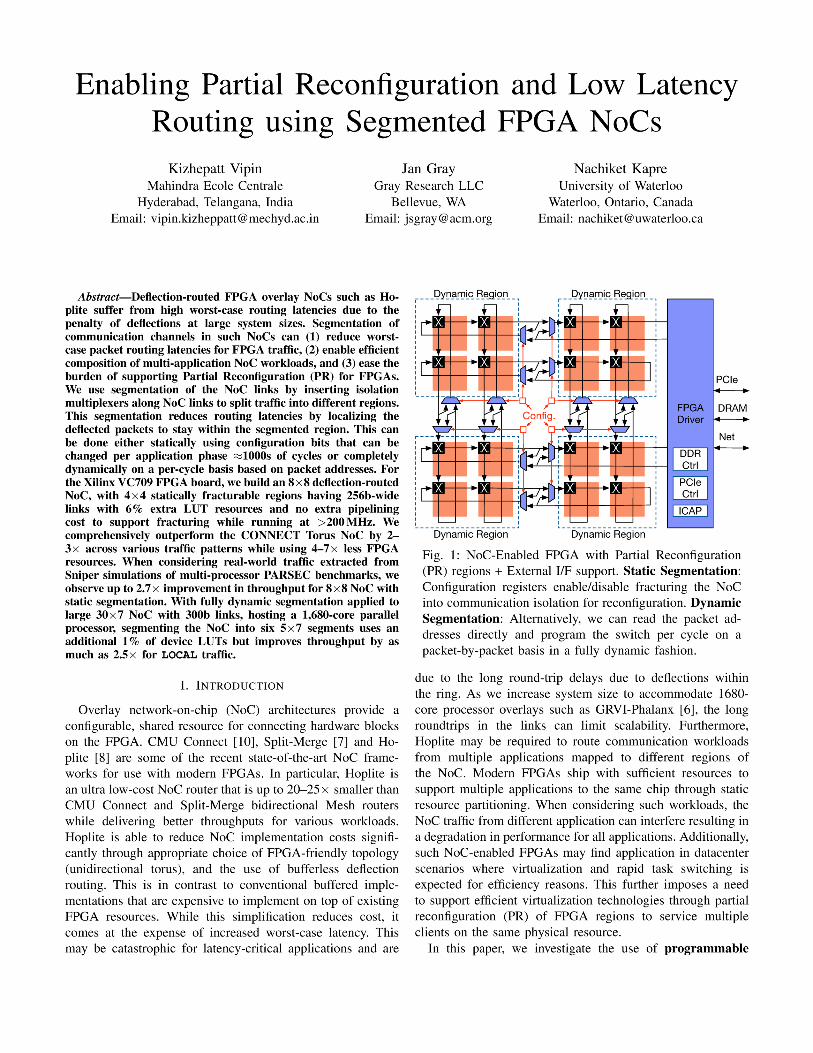
Segmentation of the NoC allows the routers to be partitioned
into isolated sub-NoCs. In Figure 1, we show a high-level
view of the FPGA NoC fabric configured for segmentation.
By controlling the isolation multiplexers in the 16×16 NoC,
we can partition the NoC into 4×4 as desired. Within an
application, this may allow reducing deflection penalties by
statically partitioning the workload requirements into local and
global phases. For multiple applications using the same NoC
at the same time, this can help statically isolate NoC traffic
and prevent interference between the workloads. The isolation
interfaces also serve as a natural boundary for configuring Par-
tial Reconfiguration regions in the FPGA CAD flow. Finally,
we can choose to drive the segmentation using packet address
information on a per-cycle basis in a fully dynamic fashion.
The key contributions of this work include:
• Design and implementation of a segmented FPGA Ho-
plite NoC that can be dynamically configured to fracture
into sub-NoCs.
• Performance evaluation of the NoC configuration under
synthetic traffic for patterns such as LOCAL, RANDOM,
TRANSPOSE, and TORNADO.
• We also consider multi-processor traces extracted
from SniperSim [3] for PARSEC: blackscholes,
bodytrack, canneal, dedup, fluidanimate,
freqmine, swaptions, vips, x264.
• Characterization of FPGA implementation costs of seg-
mented design including PR support on the Xilinx VC709
board (Xilinx XC7V690T FPGA).
• Experimental evaluation of the fractured NoC for dy-
namic segmentation and its application to the GRVI
Phalanx 30×7 NoC topology.
II. BACKGROUND
FPGA overlay NoCs such as Hoplite [8] allow FPGA
developers to compose large accelerators in a scalable manner
by combining multiple optimized compute units (Clients or
Processing Elements, i.e. PEs). Developers can focus engi-
neering and optimization effort on the small repeating com-
pute units and rely on the NoC to interconnect many of
these together. This divide-and-conquer approach works well
when the accelerator task has sufficient parallelism and can
expose communication dependencies in the form of packets.
Furthermore, the NoC also provides access to system-level
services such as DRAM controllers, PCIe links, Ethernet ports,
and other monitoring and management interfaces. With the
increasing density of modern FPGAs, we can easily fit 100s-
1000s of such small compute units. One example of such a
design is the GRVI-Phalanx [6] architecture that is able to fit
1680 RISC-V processors onto a Xilinx VU9P FPGA. Very few
applications could possibly scale to use all these processors
at the same time. Additionally, the deflection penalty when
traversing such large system sizes may cripple performance
scalability. Datacenter FPGA operators may want to virtualize
such a large compute fabric across multiple customers to
reduce costs and maximize utilization. Under this scenario,
the application mix that is mapped to such a multiprocessing
FPGA fabric would change over time. For instance, we could
partition the 1680 processor fabric into rectangular regions
assigned to different customer applications. The NoC back-
bone would retain connectivity to system-level interfaces while
applications are loaded or unloaded at runtime.
To summarize, we need to consider NoC adaptation to
handle scenarios where:
• applications may not have enough parallelism to use the
entire FPGA multiprocessing fabric,
• deflection penalty of routing packets over Hoplite may
limit performance scalability for application that do have
adequate parallelism,
• the FPGA may be partitioned across multiple separate
applications to meet customer requirements in a datacenter
environment, and
• we need to safely reconfigure portions of the FPGA while
allowing rest of the NoC-connected FPGA to continue safe
operation.
In this paper, we show how to modify Hoplite to support
configurable segmentation and satisfy these four requirements.
A segmented NoC can be dynamically fractured into multiple
smaller NoCs in such a way that no packets can travel
across the fracture boundaries. Segmenting the NoC can be
naturally tolerated by the deflection-routing function used in
Hoplite. However, this comes at extra multiplexing cost The
engineering challenge is to choose the appropriate amount of
segmentation that balances cost and deliver improved perfor-
mance and utilization.
III. SEGMENTED NOC DESIGN
In this section, we introduce the idea of segmentation to
the design of FPGA overlay NoCs like Hoplite. We describe
the high-level idea, and then discuss specific implementation
considerations for FPGA mapping.
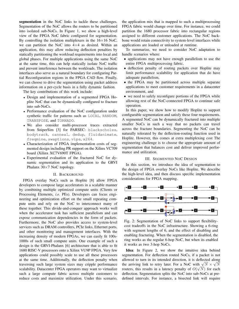
Fig. 2: Segmentation of NoC links to support flexibility-
cost tradeoffs in the NoC infrastructure. Showing a 6-ring
with segment lengths of 6, and the effect of disabling and
enabling fracturing. When the segmentation is disabled, the
ring works as the regular 6-hop NoC, but when its enabled
it works as two 3-hop NoCs.
Idea: In Figure 2, we show the intuitive idea behind
segmentation. For deflection routed NoCs, if a packet is not
allowed to turn in its intended direction, it is deflected along
the arriving link to retry later. For a NoC with√N ×
√N
routers, this results in a latency penalty of O(√N) for each
deflection. Segmentation splits the NoC into sub-NoCs at pre-
defined intervals. For instance, a bisected link will require
5
LUT5
LUT
5
LUT5
LUT3:1
MUX
5:1
MUX
WPE E
S/PE
DOR Logic
sel0 sel1,2
N
Ewrap
Swrap
Esplit
Ssplit
Ewrap
Swrap
5
LUT5
LUT
5
LUT5
LUT2:1
MUX
3:1
MUX
WPE E
S/PE
DOR Logic
sel0 sel1,2
N
5
LUT5
LUT2:1
MUX
5
LUT5
LUT
5
LUT5
LUT2:1
MUX
3:1
MUX
PE
E
S/PE
DOR Logic
sel0 sel1,2
5
LUT5
LUT2:1
MUX
W
Ewrap
N
Swrap
Esplit
Ssplit
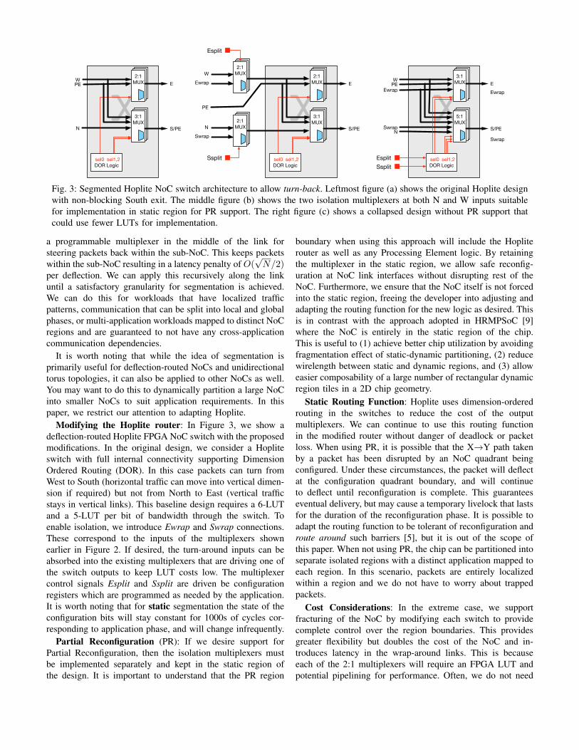
Fig. 3: Segmented Hoplite NoC switch architecture to allow turn-back. Leftmost figure (a) shows the original Hoplite design
with non-blocking South exit. The middle figure (b) shows the two isolation multiplexers at both N and W inputs suitable
for implementation in static region for PR support. The right figure (c) shows a collapsed design without PR support that
could use fewer LUTs for implementation.
a programmable multiplexer in the middle of the link for
steering packets back within the sub-NoC. This keeps packets
within the sub-NoC resulting in a latency penalty of O(√N/2)
per deflection. We can apply this recursively along the link
until a satisfactory granularity for segmentation is achieved.
We can do this for workloads that have localized traffic
patterns, communication that can be split into local and global
phases, or multi-application workloads mapped to distinct NoC
regions and are guaranteed to not have any cross-application
communication dependencies.
It is worth noting that while the idea of segmentation is
primarily useful for deflection-routed NoCs and unidirectional
torus topologies, it can also be applied to other NoCs as well.
You may want to do this to dynamically partition a large NoC
into smaller NoCs to suit application requirements. In this
paper, we restrict our attention to adapting Hoplite.
Modifying the Hoplite router: In Figure 3, we show a
deflection-routed Hoplite FPGA NoC switch with the proposed
modifications. In the original design, we consider a Hoplite
switch with full internal connectivity supporting Dimension
Ordered Routing (DOR). In this case packets can turn from
West to South (horizontal traffic can move into vertical dimen-
sion if required) but not from North to East (vertical traffic
stays in vertical links). This baseline design requires a 6-LUT
and a 5-LUT per bit of bandwidth through the switch. To
enable isolation, we introduce Ewrap and Swrap connections.
These correspond to the inputs of the multiplexers shown
earlier in Figure 2. If desired, the turn-around inputs can be
absorbed into the existing multiplexers that are driving one of
the switch outputs to keep LUT costs low. The multiplexer
control signals Esplit and Ssplit are driven be configuration
registers which are programmed as needed by the application.
It is worth noting that for static segmentation the state of the
configuration bits will stay constant for 1000s of cycles cor-
responding to application phase, and will change infrequently.
Partial Reconfiguration (PR): If we desire support for
Partial Reconfiguration, then the isolation multiplexers must
be implemented separately and kept in the static region of
the design. It is important to understand that the PR region
boundary when using this approach will include the Hoplite
router as well as any Processing Element logic. By retaining
the multiplexer in the static region, we allow safe reconfig-
uration at NoC link interfaces without disrupting rest of the
NoC. Furthermore, we ensure that the NoC itself is not forced
into the static region, freeing the developer into adjusting and
adapting the routing function for the new logic as desired. This
is in contrast with the approach adopted in HRMPSoC [9]
where the NoC is entirely in the static region of the chip.
This is useful to (1) achieve better chip utilization by avoiding
fragmentation effect of static-dynamic partitioning, (2) reduce
wirelength between static and dynamic regions, and (3) allow
easier composability of a large number of rectangular dynamic
region tiles in a 2D chip geometry.
Static Routing Function: Hoplite uses dimension-ordered
routing in the switches to reduce the cost of the output
multiplexers. We can continue to use this routing function
in the modified router without danger of deadlock or packet
loss. When using PR, it is possible that the X→Y path taken
by a packet has been disrupted by an NoC quadrant being
configured. Under these circumstances, the packet will deflect
at the configuration quadrant boundary, and will continue
to deflect until reconfiguration is complete. This guarantees
eventual delivery, but may cause a temporary livelock that lasts
for the duration of the reconfiguration phase. It is possible to
adapt the routing function to be tolerant of reconfiguration and
route around such barriers [5], but it is out of the scope of
this paper. When not using PR, the chip can be partitioned into
separate isolated regions with a distinct application mapped to
each region. In this scenario, packets are entirely localized
within a region and we do not have to worry about trapped
packets.
Cost Considerations: In the extreme case, we support
fracturing of the NoC by modifying each switch to provide
complete control over the region boundaries. This provides
greater flexibility but doubles the cost of the NoC and in-
troduces latency in the wrap-around links. This is because
each of the 2:1 multiplexers will require an FPGA LUT and
potential pipelining for performance. Often, we do not need

complete flexibility, and we can stagger these turn-enabled
switches at specific intervals. Thus, to control costs, we may
add switches with only Ewrap links, or Swrap links alone,
or together. We can choose the staggering (or GAP) between
these isolation multiplexers to expose a coarser-grained design
for reconfiguration.
IV. DYNAMIC SEGMENTATION AND SHORTCUT ROUTERS
With static segmentation of the NoC, the isolation mul-
tiplexers may be programmed to partition the NoC rings
into regions for prolonged periods of time before they are
reconfigured, potentially thousands of clock cycles. Instead of
(or in addition to) such static segmentation, a NoC overlay may
also be designed with dynamic segmentation that automatically
partition rings into segments on a packet-by-packet basis per
cycle. A dynamic shortcut router that implements this behavior
will selectively convey packets between ring segments when
necessary, or else reflects them back into their current ring
segments, a kind of “Maxwell’s demon” that improves NoC
routing outcomes.
In contrast to the programmed segmentation of the prior
section, dynamic segmentation still allows delivery of a packet
to any destination across the full NoC. However, this comes
at the cost of more LUTs for determining routing conditions
dynamically based on packet addresses as well as making par-
tial reconfiguration support more complicated. We also need
to pay an extra two cycle of latency for each dynamic router
in the ring. We can use the router microarchitectures shown
in Figure 3(b) and (c) with the only modification to drive the
Esplit and Ssplit mux control signals based on packet addresses
instead of configuration registers (static segmentation).
When designing the shortcut routing function, we must
take care of one contention scenario to avoid livelock. When
packets arriving at a segment junction from either direction
of the ring are destined for a client in the same side of the
segmented ring there is output port contention. We resolve this
in favour of the segment-crossing packet so that it is given
right of way. The other packet is forced to continue along
the ring and will incur additional delivery latency, but never
livelock. This is because, it is sure to loop around the whole
ring and arrive at the segment junction with a higher priority
should we have a contention again.
V. METHODOLOGY
In this section, we describe our evaluation methodology and
present implementation details relevant for understanding the
experiments.
RTL Implementation: We compile the various configura-
tions under an identical NoC linkwidth of 256b to match the
throughput of DRAM/PCIe interfaces of the VC709 FPGA
board. Our test setup includes a static region (shown in
Figure 1 earlier) that interfaces our NoC with external system-
level interfaces. We tabulate the resource costs and implemen-
tation metrics of the various NoC configurations in Table I.
Here we only consider NoC cost and do not include other costs
(PE logic, static region). It is clear that segmentation adds an
overhead to each router, particularly the number of registers.
We also introduce PR region boundaries around the NoC
router which constrains place and route freedom in the CAD
tools. This does not add much resource overhead (<1%) but
does reduce clock frequency by ≈20–50 MHz. We use Vivado
2016.4 installed on a 64 GB Ubuntu 16.04 platform (higher
memory recommended for larger NoC size compilations) for
our implementation experiments and evaluate correctness on
the VC709 board. For enabling Partial Reconfiguration we use
a custom ICAP controller [12] that can reconfigure the FPGA
at ≈380 MB/s. For a 2×2 region with 7.2K LUTs, 14.4K FFs
40 RAMB18 and 40 DSP48s it takes 1.2 ms to reconfigure that
portion of the FPGA. The static region of the design contains
DyRact v4.1, PCIe Gen3 v3.2, MIG v2.4, and AXI Datamover
v5.1 rev9 IPs to provide system-level IO interfaces.
CONNECT Torus reference: We also compare our imple-
mentation with the CMU CONNECT [10] Torus router. Unlike
the original Hoplite comparison [8], we do not compare against
a Bidirectional Mesh with Virtual Channels, but generate a
Unidirectional Torus router with Simple Input Queues that is
structurally similar to Hoplite. We use the online NoC Verilog
generator at the CMU CONNECT site to produce RTL for
the following configuration: (1) Torus topology, (2) System
sizes from 2×2 to 12×12 (upper limit of the CONNECT tool),
(3) Simple Input Queues (no virtual channels for simplicity),
(4) Peek Flow Control, (5) flit datawidth of 256b, and (6)
flit buffer depth of 8. From Table I, we observe that this
CONNECT configuration requires 6.8–7.2× more LUTs than
equivalent Hoplite NoCs. This is expected as the Flit buffers,
and complex switch control logic occupy substantial area
on the chip. But it is worth noting that this gap is smaller
than the 20–25× resource savings possible when comparing
Hoplite to the Bidirectional Mesh CONNECT router. We
believe this new ≈7× resource advantage for Hoplite is a
fairer comparison against the CONNECT NoC generator1. In
addition, the Hoplite NoC does use 10–12× more FFs than
CONNECT due to the inter-router 4-stage pipelining for faster
performance. This is necessary for die-spanning layouts of the
NoCs particularly for smaller sizes. As expected, this reduced
FF cost comes at the expense of a significantly slower design
that runs as much as 2.4–3× slower than Hoplite.
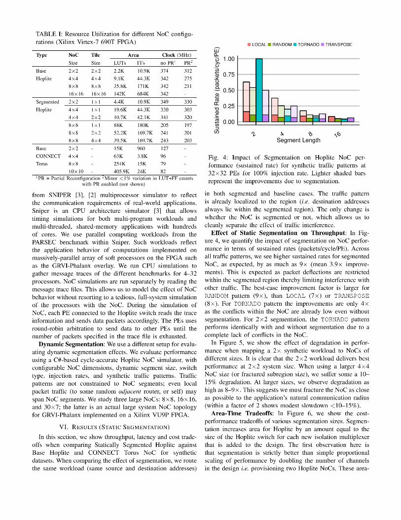
NoC Traffic: We consider synthetic workloads for different
traffic patterns such as LOCAL, RANDOM, TRANSPOSE and
TORNADO for our study. We consider 100% injection rates to
saturate the NoC and sweep various PE counts from 2×2, to
32×32 in powers of 2. We also consider segmentation sizes
from 1×1 (full segmentation), to 32×32 (no segmentation).
We use RTL simulations to evaluate these different traffic
patterns and record overall sustained throughputs (packets/-
cycle/PE) and per-packet latency metrics in the simulation.
When reporting performance compared to CONNECT NoC,
we consider frequency and resource costs. In addition to
synthetic benchmarks, we also extract communication traces
1A smaller version of Hoplite can be compiled with 1 LUT6 2 per bitby cascading E→S mux. This will be 2× smaller, and have slightly lowerperformance, than the Base Hoplite used in this paper
●
●
●
●
●
0.25
0.50
0.75
1.00
2 4 8 16 32NoC Ring Dimension
Susta
ined R
ate
(packets
/cyc/P
E) ● LOCAL RANDOM TORNADO TRANSPOSE
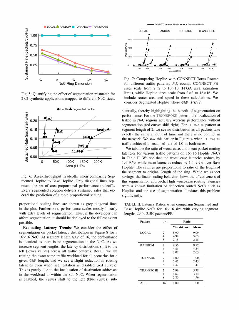
Fig. 5: Quantifying the effect of segmentation mismatch for
2×2 synthetic applications mapped to different NoC sizes.
16x1616x1616x1616x1616x1616x1616x1616x1616x16
[8x8][8x8][8x8][8x8][8x8][8x8][8x8][8x8][8x8]
[4x4][4x4][4x4][4x4][4x4][4x4][4x4][4x4][4x4]
[2x2][2x2][2x2][2x2][2x2][2x2][2x2][2x2][2x2]
8x88x88x88x88x88x88x88x88x8
[4x4][4x4][4x4][4x4][4x4][4x4][4x4][4x4][4x4]
[2x2][2x2][2x2][2x2][2x2][2x2][2x2][2x2][2x2]
4x44x44x44x44x44x44x44x44x4
[2x2][2x2][2x2][2x2][2x2][2x2][2x2][2x2][2x2]
●
●
●
0.00
0.05
0.10
0.15
0.20
0 50K 100K 150K 200K
Area (LUTs)
Susta
ined R
ate
(packets
/PE
/ns)
● Hoplite Segmented Hoplite
Fig. 6: Area-Throughput Tradeoffs when comparing Seg-
mented Hoplite to Base Hoplite. Grey diagonal lines rep-
resent the set of area-proportional performance tradeoffs.
Every segmented solution delivers sustained rates that ex-
ceed the prediction of simple proportional scaling.
proportional scaling lines are shown as grey diagonal lines
in the plot. Furthermore, performance scales mostly linearly
with extra levels of segmentation. Thus, if the developer can
afford segmentation, it should be deployed to the fullest extent
possible.
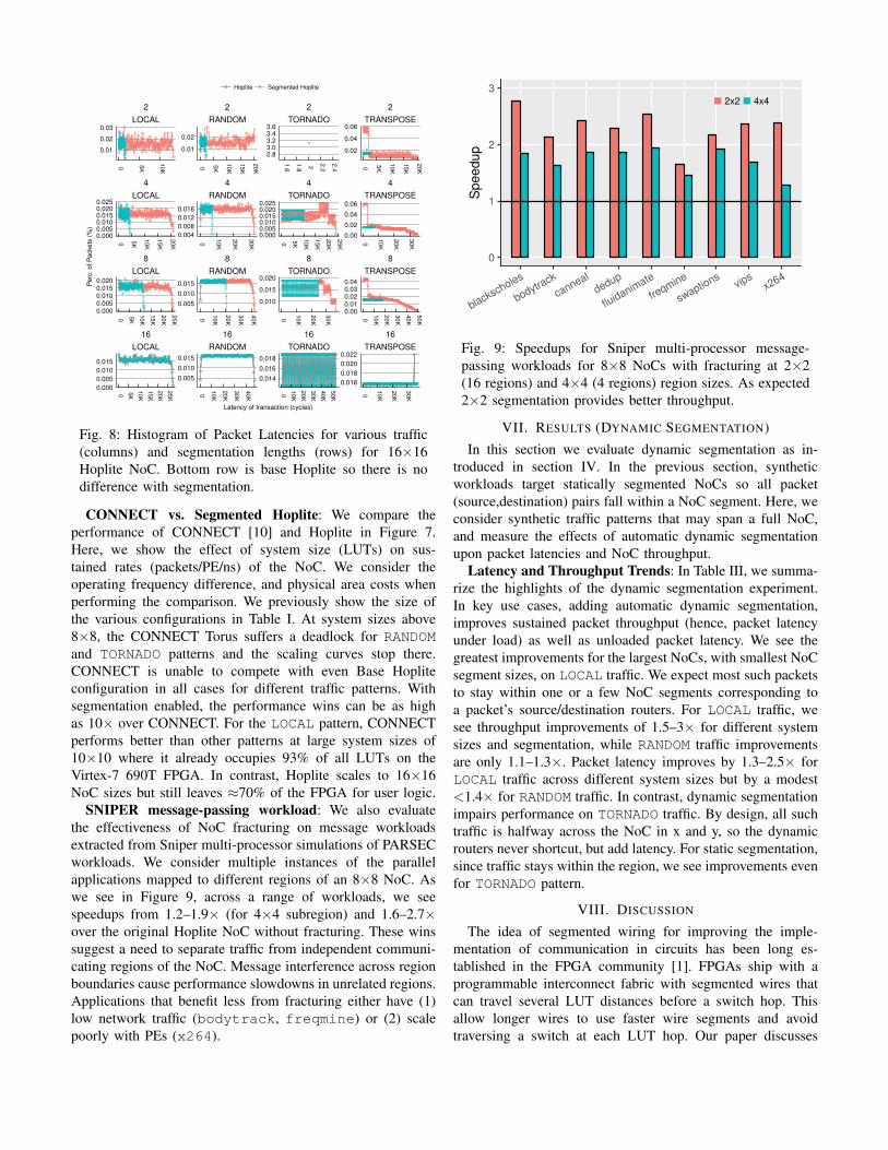
Evaluating Latency Trends: We consider the effect of
segmentation on packet latency distribution in Figure 8 for a
16×16 NoC. At segment length GAP of 16, the performance
is identical as there is no segmentation in the NoC. As we
increase segment lengths, the latency distributions shift to the
left (lower values) across all traffic patterns. Recall, we are
routing the exact same traffic workload for all scenarios for a
given GAP length, and we see a slight reduction in routing
latencies even when segmentation is disabled (red curves).
This is purely due to the localization of destination addresses
in the workload to within the sub-NoC. When segmentation
is enabled, the curves shift to the left (blue curves) sub-
●
●
●
●
● ●●
●
● ●
●
LOCAL RANDOM TORNADO TRANSPOSE
10K 100K 10K 100K 10K 100K 10K 100K
0
1000
2000
3000
Area (LUTs)
Packets
/PE
/ns
CONNECT Hoplite Segmented Hoplite
Fig. 7: Comparing Hoplite with CONNECT Torus Router
for different traffic patterns, PE counts. CONNECT PE
sizes scale from 2×2 to 10×10 (FPGA area saturation
limit), while Hoplite sizes scale from 2×2 to 16×16. We
include router area and speed in these calculations. We
consider Segmented Hoplite where GAP=PE/2.
stantially, thereby highlighting the benefit of segmentation on
performance. For the TRANSPOSE pattern, the localization of
traffic in NoC regions actually worsens performance without
segmentation (red curves shift right). For TORNADO pattern at
segment length of 2, we see no distribution as all packets take
exactly the same amount of time and there is no conflict in
the network. We saw this earlier in Figure 4 when TORNADO
traffic achieved a sustained rate of 1.0 in both cases.
We tabulate the ratio of worst-case, and mean packet routing
latencies for various traffic patterns on 16×16 Hoplite NoCs
in Table II. We see that the worst case latencies reduce by
1.4–9.5× while mean latencies reduce by 1.4–9.9× over Base
Hoplite. The savings are proportional to ratio of the length of
the segment to original length of the ring. While we expect
savings, the linear scaling behavior shows the effectiveness of
this segmentation approach. High worst-case routing latencies
were a known limitation of deflection routed NoCs such as
Hoplite, and the use of segmentation alleviates this problem
significantly.
TABLE II: Latency Ratios when comparing Segmented and
Base Hoplite NoCs for 16×16 size with varying segment
lengths GAP, 2.5K packets/PE.
Pattern GAP Ratio
Worst-Case Mean
LOCAL 2 8.90 9.094 4.98 5.058 2.15 2.15
RANDOM 2 9.56 9.924 4.51 4.548 2.07 2.05
TORNADO 2 1.00 1.004 2.42 2.458 1.47 1.41
TRANSPOSE 2 7.99 5.784 4.67 3.148 2.86 1.96
ALL 16 1.00 1.00
16
LOCAL
16
RANDOM
16
TORNADO
16
TRANSPOSE
8
LOCAL
8
RANDOM
8
TORNADO
8
TRANSPOSE
4
LOCAL
4
RANDOM
4
TORNADO
4
TRANSPOSE
2
LOCAL
2
RANDOM
2
TORNADO
2
TRANSPOSE
0 5K
10
K
15
K
20
K
25
K
0
10
K
20
K
30
K
40
K
0
10
K
20
K
30
K
40
K
50
K
0
10
K
20
K
30
K
0 5K
10
K
15
K
20
K
25
K
0
10
K
20
K
30
K
40
K
0
10
K
20
K
30
K
0
10
K
20
K
30
K
40
K
50
K
0 5K
10
K
15
K
20
K
0
10
K
20
K
30
K
0 5K
10
K
15
K
20
K
25
K
0
10
K
20
K
30
K
0 5K
10
K
0 5K
10
K
15
K
20
K
1.6
1.8 2 2.2
2.4 0 5K
10
K
15
K
20
K
0.02
0.04
0.06
0.00
0.02
0.04
0.06
0.000.010.020.030.04
0.016
0.018
0.020
0.022
2.83.03.23.43.6
0.0000.0050.0100.0150.0200.025
0.010
0.015
0.020
0.014
0.016
0.018
0.01
0.02
0.004
0.008
0.012
0.016
0.005
0.010
0.015
0.005
0.010
0.015
0.01
0.02
0.03
0.0000.0050.0100.0150.0200.025
0.0000.0050.0100.0150.020
0.000
0.005
0.010
0.015
Latency of transaction (cycles)
Perc
. of P
ackets
(%
)Hoplite Segmented Hoplite
Fig. 8: Histogram of Packet Latencies for various traffic
(columns) and segmentation lengths (rows) for 16×16
Hoplite NoC. Bottom row is base Hoplite so there is no
difference with segmentation.
CONNECT vs. Segmented Hoplite: We compare the
performance of CONNECT [10] and Hoplite in Figure 7.
Here, we show the effect of system size (LUTs) on sus-
tained rates (packets/PE/ns) of the NoC. We consider the
operating frequency difference, and physical area costs when
performing the comparison. We previously show the size of
the various configurations in Table I. At system sizes above
8×8, the CONNECT Torus suffers a deadlock for RANDOM
and TORNADO patterns and the scaling curves stop there.
CONNECT is unable to compete with even Base Hoplite
configuration in all cases for different traffic patterns. With
segmentation enabled, the performance wins can be as high
as 10× over CONNECT. For the LOCAL pattern, CONNECT
performs better than other patterns at large system sizes of
10×10 where it already occupies 93% of all LUTs on the
Virtex-7 690T FPGA. In contrast, Hoplite scales to 16×16
NoC sizes but still leaves ≈70% of the FPGA for user logic.
SNIPER message-passing workload: We also evaluate
the effectiveness of NoC fracturing on message workloads
extracted from Sniper multi-processor simulations of PARSEC
workloads. We consider multiple instances of the parallel
applications mapped to different regions of an 8×8 NoC. As
we see in Figure 9, across a range of workloads, we see
speedups from 1.2–1.9× (for 4×4 subregion) and 1.6–2.7×over the original Hoplite NoC without fracturing. These wins
suggest a need to separate traffic from independent communi-
cating regions of the NoC. Message interference across region
boundaries cause performance slowdowns in unrelated regions.
Applications that benefit less from fracturing either have (1)
low network traffic (bodytrack, freqmine) or (2) scale
poorly with PEs (x264).
0
1
2
3
blackscholes
bodytrack
canneal
dedup
fluidanim
ate
freqmine
swaptions
vipsx264
Speedup
2x2 4x4
Fig. 9: Speedups for Sniper multi-processor message-
passing workloads for 8×8 NoCs with fracturing at 2×2
(16 regions) and 4×4 (4 regions) region sizes. As expected
2×2 segmentation provides better throughput.
VII. RESULTS (DYNAMIC SEGMENTATION)
In this section we evaluate dynamic segmentation as in-
troduced in section IV. In the previous section, synthetic
workloads target statically segmented NoCs so all packet
(source,destination) pairs fall within a NoC segment. Here, we
consider synthetic traffic patterns that may span a full NoC,
and measure the effects of automatic dynamic segmentation
upon packet latencies and NoC throughput.
Latency and Throughput Trends: In Table III, we summa-
rize the highlights of the dynamic segmentation experiment.
In key use cases, adding automatic dynamic segmentation,
improves sustained packet throughput (hence, packet latency
under load) as well as unloaded packet latency. We see the
greatest improvements for the largest NoCs, with smallest NoC
segment sizes, on LOCAL traffic. We expect most such packets
to stay within one or a few NoC segments corresponding to
a packet’s source/destination routers. For LOCAL traffic, we
see throughput improvements of 1.5–3× for different system
sizes and segmentation, while RANDOM traffic improvements
are only 1.1–1.3×. Packet latency improves by 1.3–2.5× for
LOCAL traffic across different system sizes but by a modest
<1.4× for RANDOM traffic. In contrast, dynamic segmentation
impairs performance on TORNADO traffic. By design, all such
traffic is halfway across the NoC in x and y, so the dynamic
routers never shortcut, but add latency. For static segmentation,
since traffic stays within the region, we see improvements even
for TORNADO pattern.
VIII. DISCUSSION
The idea of segmented wiring for improving the imple-
mentation of communication in circuits has been long es-
tablished in the FPGA community [1]. FPGAs ship with a
programmable interconnect fabric with segmented wires that
can travel several LUT distances before a switch hop. This
allow longer wires to use faster wire segments and avoid
traversing a switch at each LUT hop. Our paper discusses
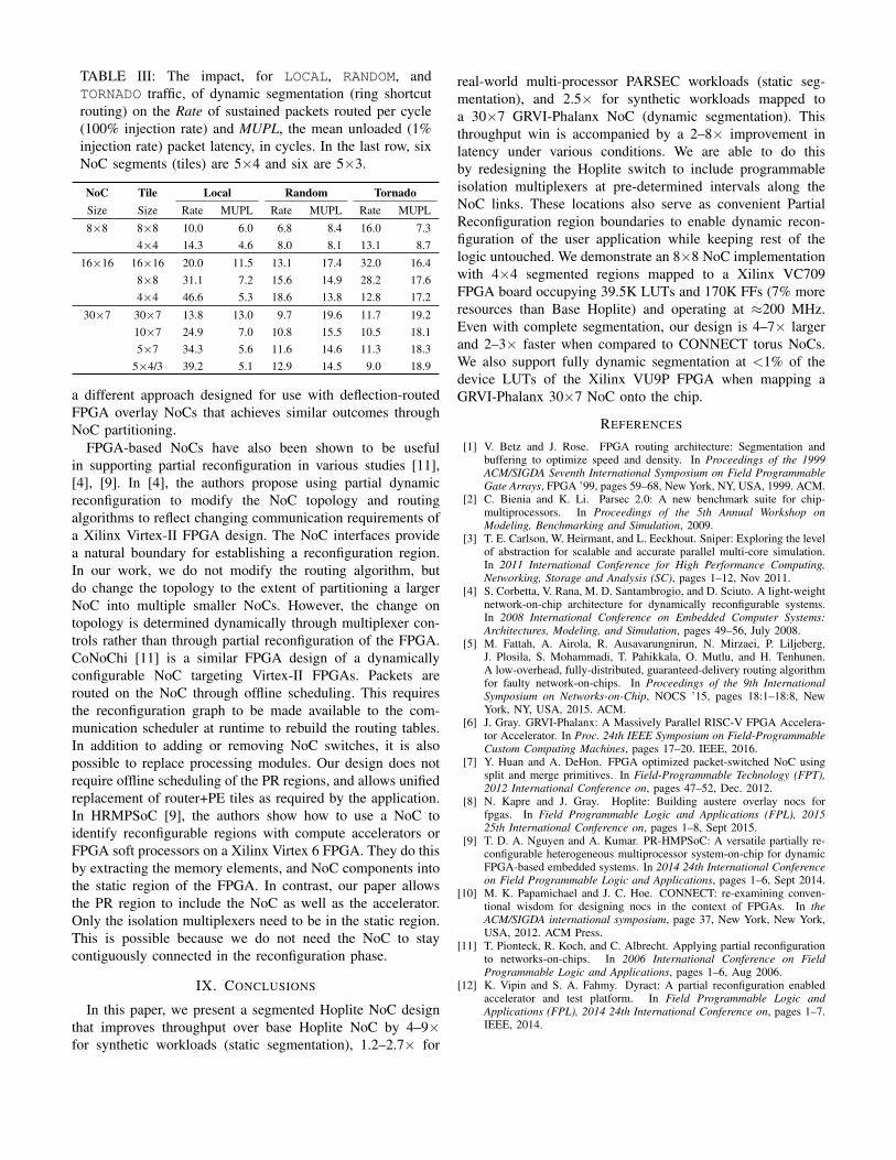
TABLE III: The impact, for LOCAL, RANDOM, and
TORNADO traffic, of dynamic segmentation (ring shortcut
routing) on the Rate of sustained packets routed per cycle
(100% injection rate) and MUPL, the mean unloaded (1%
injection rate) packet latency, in cycles. In the last row, six
NoC segments (tiles) are 5×4 and six are 5×3.
NoC Tile Local Random Tornado
Size Size Rate MUPL Rate MUPL Rate MUPL
8×8 8×8 10.0 6.0 6.8 8.4 16.0 7.3
4×4 14.3 4.6 8.0 8.1 13.1 8.7
16×16 16×16 20.0 11.5 13.1 17.4 32.0 16.4
8×8 31.1 7.2 15.6 14.9 28.2 17.6
4×4 46.6 5.3 18.6 13.8 12.8 17.2
30×7 30×7 13.8 13.0 9.7 19.6 11.7 19.2
10×7 24.9 7.0 10.8 15.5 10.5 18.1
5×7 34.3 5.6 11.6 14.6 11.3 18.3
5×4/3 39.2 5.1 12.9 14.5 9.0 18.9
a different approach designed for use with deflection-routed
FPGA overlay NoCs that achieves similar outcomes through
NoC partitioning.
FPGA-based NoCs have also been shown to be useful
in supporting partial reconfiguration in various studies [11],
[4], [9]. In [4], the authors propose using partial dynamic
reconfiguration to modify the NoC topology and routing
algorithms to reflect changing communication requirements of
a Xilinx Virtex-II FPGA design. The NoC interfaces provide
a natural boundary for establishing a reconfiguration region.
In our work, we do not modify the routing algorithm, but
do change the topology to the extent of partitioning a larger
NoC into multiple smaller NoCs. However, the change on
topology is determined dynamically through multiplexer con-
trols rather than through partial reconfiguration of the FPGA.
CoNoChi [11] is a similar FPGA design of a dynamically
configurable NoC targeting Virtex-II FPGAs. Packets are
routed on the NoC through offline scheduling. This requires
the reconfiguration graph to be made available to the com-
munication scheduler at runtime to rebuild the routing tables.
In addition to adding or removing NoC switches, it is also
possible to replace processing modules. Our design does not
require offline scheduling of the PR regions, and allows unified
replacement of router+PE tiles as required by the application.
In HRMPSoC [9], the authors show how to use a NoC to
identify reconfigurable regions with compute accelerators or
FPGA soft processors on a Xilinx Virtex 6 FPGA. They do this
by extracting the memory elements, and NoC components into
the static region of the FPGA. In contrast, our paper allows
the PR region to include the NoC as well as the accelerator.
Only the isolation multiplexers need to be in the static region.
This is possible because we do not need the NoC to stay
contiguously connected in the reconfiguration phase.
IX. CONCLUSIONS
In this paper, we present a segmented Hoplite NoC design
that improves throughput over base Hoplite NoC by 4–9×for synthetic workloads (static segmentation), 1.2–2.7× for
real-world multi-processor PARSEC workloads (static seg-
mentation), and 2.5× for synthetic workloads mapped to
a 30×7 GRVI-Phalanx NoC (dynamic segmentation). This
throughput win is accompanied by a 2–8× improvement in
latency under various conditions. We are able to do this
by redesigning the Hoplite switch to include programmable
isolation multiplexers at pre-determined intervals along the
NoC links. These locations also serve as convenient Partial
Reconfiguration region boundaries to enable dynamic recon-
figuration of the user application while keeping rest of the
logic untouched. We demonstrate an 8×8 NoC implementation
with 4×4 segmented regions mapped to a Xilinx VC709
FPGA board occupying 39.5K LUTs and 170K FFs (7% more
resources than Base Hoplite) and operating at ≈200 MHz.
Even with complete segmentation, our design is 4–7× larger
and 2–3× faster when compared to CONNECT torus NoCs.
We also support fully dynamic segmentation at <1% of the
device LUTs of the Xilinx VU9P FPGA when mapping a
GRVI-Phalanx 30×7 NoC onto the chip.
REFERENCES
[1] V. Betz and J. Rose. FPGA routing architecture: Segmentation andbuffering to optimize speed and density. In Proceedings of the 1999
ACM/SIGDA Seventh International Symposium on Field Programmable
Gate Arrays, FPGA ’99, pages 59–68, New York, NY, USA, 1999. ACM.[2] C. Bienia and K. Li. Parsec 2.0: A new benchmark suite for chip-
multiprocessors. In Proceedings of the 5th Annual Workshop on
Modeling, Benchmarking and Simulation, 2009.[3] T. E. Carlson, W. Heirmant, and L. Eeckhout. Sniper: Exploring the level
of abstraction for scalable and accurate parallel multi-core simulation.In 2011 International Conference for High Performance Computing,
Networking, Storage and Analysis (SC), pages 1–12, Nov 2011.[4] S. Corbetta, V. Rana, M. D. Santambrogio, and D. Sciuto. A light-weight
network-on-chip architecture for dynamically reconfigurable systems.In 2008 International Conference on Embedded Computer Systems:
Architectures, Modeling, and Simulation, pages 49–56, July 2008.[5] M. Fattah, A. Airola, R. Ausavarungnirun, N. Mirzaei, P. Liljeberg,
J. Plosila, S. Mohammadi, T. Pahikkala, O. Mutlu, and H. Tenhunen.A low-overhead, fully-distributed, guaranteed-delivery routing algorithmfor faulty network-on-chips. In Proceedings of the 9th International
Symposium on Networks-on-Chip, NOCS ’15, pages 18:1–18:8, NewYork, NY, USA, 2015. ACM.
[6] J. Gray. GRVI-Phalanx: A Massively Parallel RISC-V FPGA Accelera-tor Accelerator. In Proc. 24th IEEE Symposium on Field-Programmable
Custom Computing Machines, pages 17–20. IEEE, 2016.[7] Y. Huan and A. DeHon. FPGA optimized packet-switched NoC using
split and merge primitives. In Field-Programmable Technology (FPT),
2012 International Conference on, pages 47–52, Dec. 2012.[8] N. Kapre and J. Gray. Hoplite: Building austere overlay nocs for
fpgas. In Field Programmable Logic and Applications (FPL), 2015
25th International Conference on, pages 1–8, Sept 2015.[9] T. D. A. Nguyen and A. Kumar. PR-HMPSoC: A versatile partially re-
configurable heterogeneous multiprocessor system-on-chip for dynamicFPGA-based embedded systems. In 2014 24th International Conference
on Field Programmable Logic and Applications, pages 1–6, Sept 2014.[10] M. K. Papamichael and J. C. Hoe. CONNECT: re-examining conven-
tional wisdom for designing nocs in the context of FPGAs. In the
ACM/SIGDA international symposium, page 37, New York, New York,USA, 2012. ACM Press.
[11] T. Pionteck, R. Koch, and C. Albrecht. Applying partial reconfigurationto networks-on-chips. In 2006 International Conference on Field
Programmable Logic and Applications, pages 1–6, Aug 2006.[12] K. Vipin and S. A. Fahmy. Dyract: A partial reconfiguration enabled
accelerator and test platform. In Field Programmable Logic and
Applications (FPL), 2014 24th International Conference on, pages 1–7.IEEE, 2014.

![with Physical Design Awareness Unlock the NoC ...cbatten/pdfs/batten... · • Physical-Design Issues for NOCs •Open-Source Hardware for NOCs Celerity System-on-Chip [IEEE-Micro’18,VLSI’19]](https://static.documents.pub/doc/80x56/601725f4f94dcf263048972d/with-physical-design-awareness-unlock-the-noc-cbattenpdfsbatten-a-physical-design.jpg)


![Networks-on-Chips: Theory and PracticeAn overview of the cost considerations on the design of NoCs is given at [9]. Up to now NoC designs were limited to two dimensions. But the currently](https://static.documents.pub/doc/80x56/5f24771cdaf22f254b25cc28/networks-on-chips-theory-and-practice-an-overview-of-the-cost-considerations-on.jpg)


![Performance Implications of NoCs on 3D-Stacked Memories: … · 2020-07-09 · memory controllers (i.e., vault controllers), connected via an internal network-on-chip (NoC) [5]. As](https://static.documents.pub/doc/80x56/5f98c931eb5eed0afe531eb7/performance-implications-of-nocs-on-3d-stacked-memories-2020-07-09-memory-controllers.jpg)

