47
02/06/22 1 SEIMENS EWSD Engr.NOOR HAKIM Engr.NOOR HAKIM ADE Phones NTC Peshawar ADE Phones NTC Peshawar
| Date post: | 18-Nov-2014 |
| Category: |
Documents |
| Upload: | abdul-hadi |
| View: | 230 times |
| Download: | 14 times |
04/08/23 1
SEIMENS EWSD
Engr.NOOR HAKIMEngr.NOOR HAKIM
ADE Phones NTC PeshawarADE Phones NTC Peshawar
04/08/23 2
Introduction to the EWSD system
The EWSD system is divided into different functional areas called subsystems coordinated by a central system
Each subsystem having its own microprocessor control example: Group Processor in the LTG (Line /Trunk Group) in the functional area of Access.
The may be divided into the following units
Control Switching Signaling Access Power
04/08/23 3
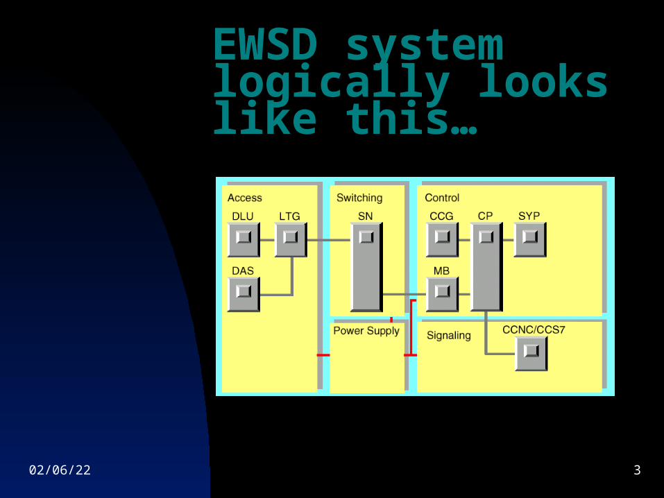
EWSD system logically looks like this…
04/08/23 4
Control
Control belongs to the area which is responsible for the coordination of the various subunits. Control consists of the following:
Coordination Processor (CP) Message Buffer (MB) System Panel (SYP) Central Clock Generator (CCG)
04/08/23 5
ControlCoordination Processor
The CP performs the following functions in a network node: Call processing Operation and maintenance Safeguarding
04/08/23 6
ControlCP (continued…)
The CP consists of the following processors:
Base Processors Call Processors Input / Output Control Bus for Common Memory Common Memory Input / Output Processors
04/08/23 7
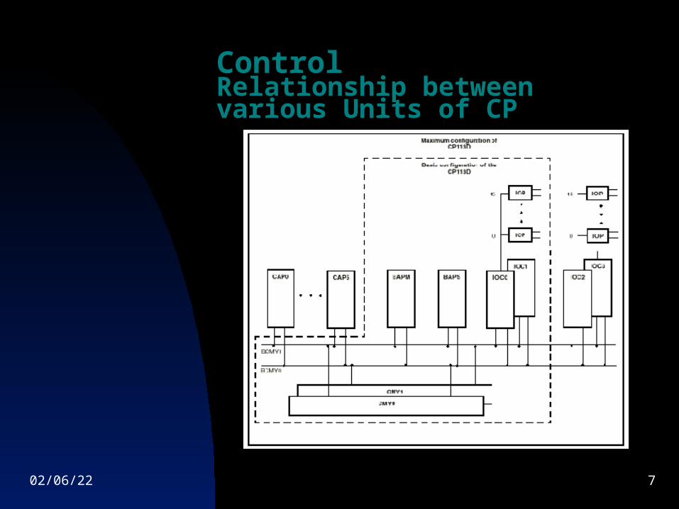
ControlRelationship between various Units of CP
04/08/23 8
ControlVarious CP units explained
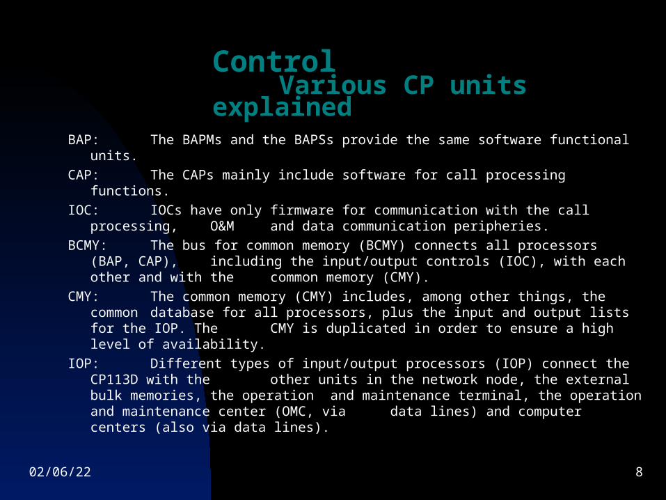
BAP: The BAPMs and the BAPSs provide the same software functional units.
CAP: The CAPs mainly include software for call processing functions.
IOC: IOCs have only firmware for communication with the call processing, O&M and data communication peripheries.
BCMY: The bus for common memory (BCMY) connects all processors (BAP, CAP), including the input/output controls (IOC), with each other and with the common memory (CMY).
CMY: The common memory (CMY) includes, among other things, the common database for all processors, plus the input and output lists for the IOP.
The CMY is duplicated in order to ensure a high level of availability.
IOP: Different types of input/output processors (IOP) connect the CP113D with the other units in the network node, the external bulk memories, the operation
and maintenance terminal, the operation and maintenance center (OMC, via data lines) and computer centers (also via data lines).
04/08/23 9
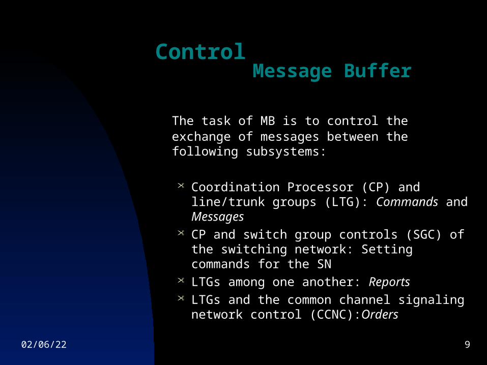
ControlMessage Buffer
The task of MB is to control the exchange of messages between the following subsystems:
Coordination Processor (CP) and line/trunk
groups (LTG): Commands and Messages CP and switch group controls (SGC) of the
switching network: Setting commands for the SN
LTGs among one another: Reports LTGs and the common channel signaling
network control (CCNC):Orders
04/08/23 10
ControlMessage Buffer Continued…
Message Buffer Group:The message buffer is divided into functional groups called Message Buffer Groups according to the expansion concept. One message buffer group consists of one message buffer unit for Switch Group Control and two message buffer units for LTG.
In the least configuration, at least one message buffer group may exist with at least one MBUL and one MBUS active where as the other MBUL may be inactive.
In the highest configuration, there are up to 4 message buffer groups with 4 MBUS and 8 MBUL.
04/08/23 11
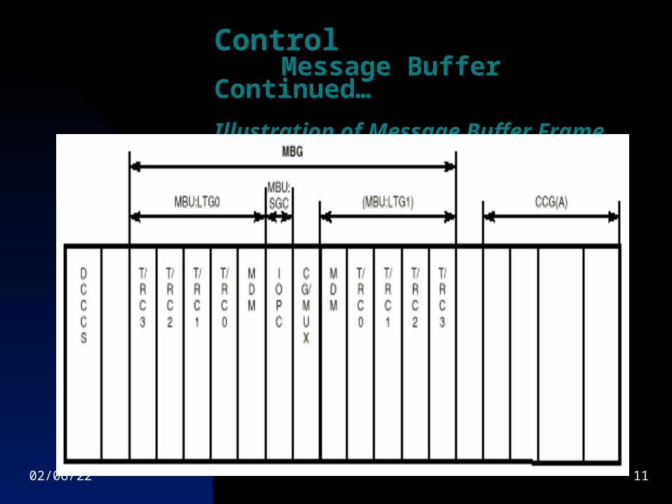
ControlMessage Buffer Continued…
Illustration of Message Buffer Frame
04/08/23 12
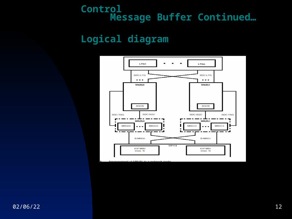
ControlMessage Buffer Continued…
Logical diagram
04/08/23 13
ControlCentral Clock Generator
In order to switch and transmit digital information, the sequence of operations must be synchronous throughout the equipment involved.
This requires a clock supply with a high level of reliability, precision and consistency for all the nodes in the digital network.
This task is fulfilled by the central clock generator (CCG).
04/08/23 14
ControlCentral Clock Generator
(Continued…)
Depending upon the accuracy required, the following two modes of
operation are possible:
Synchronous: with external reference frequencies (fR): the precision of the CCG output clocks depends here on the tolerance of the controlling reference frequency. The tolerance in synchronous networks with international digital traffic and synchronization of the master nodes by cesium (Cs) standards is: (CCITT G.811).
Plesiochronous: (self-synchronization) without external reference frequencies for the master nodes in national synchronous networks (without international digital traffic). The precision of the CCG output clocks depends here on the tolerance of the oscillator frequency generated in the master CCG. This tolerance is: 10-8
04/08/23 15
ControlSystem Panel
The purpose of the system panel is to display alarms and advisories of internal and external supervisory units outside
the system) both visually and acoustically.
It is divided into two parts namely the System Panel Control and the System Panel Display unit.
04/08/23 16
ControlSystem Panel (Continued…)
System Panel Control
This utilizes the free space in the Message Buffer Rack. It is connected with the IOP:MB in the CP113.
Although itself it is not redundant, it has a redundant connection with the CP via two IOP:MBs, each belonging to a different side.
04/08/23 17
ControlSystem Panel (Continued…)
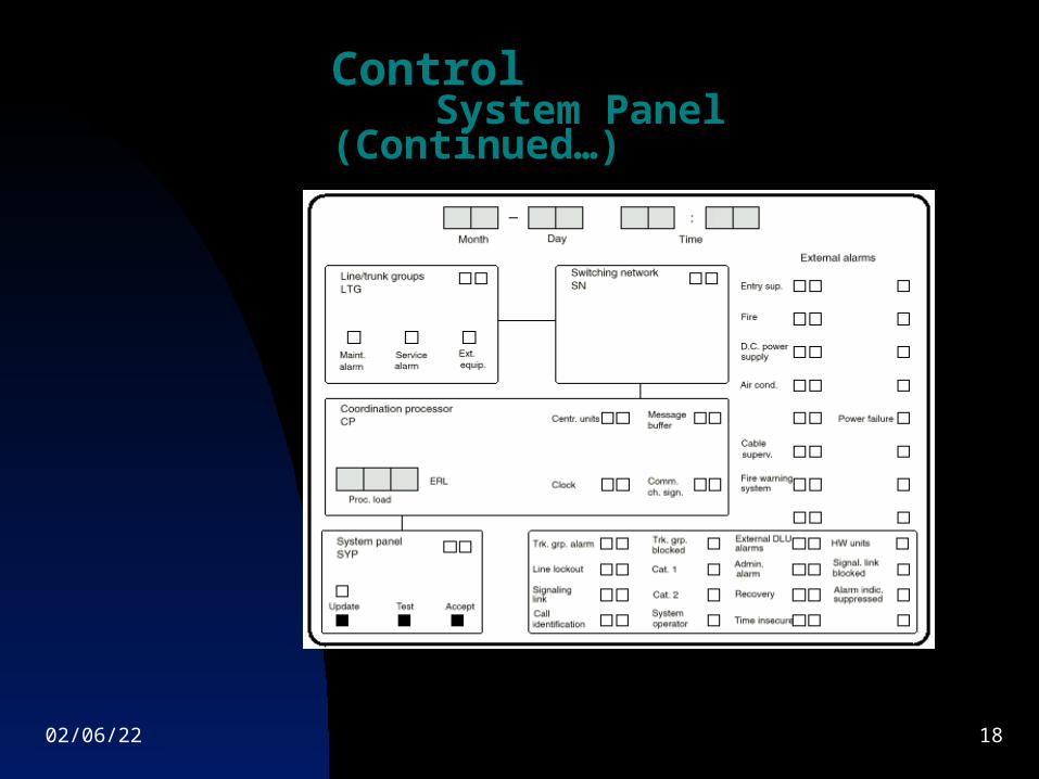
System Panel Display
The system panel display unit is connected with the control (SYP) via a cable but can be placed at any suitable place within the exchange by direct connection or in an OMC using some transmission system.
This unit is responsible to display alarms and advisories of internal and external supervisory units (outside the system) both visually and acoustically. It is also responsible to show the CP load(in ERL) and the current date and time of the system.
04/08/23 18
ControlSystem Panel (Continued…)
04/08/23 19
Switching
By virtue of its high data transmission quality, the switching network can switch connections for various types of service (for example telephony, facsimile, teletext, data transmission).
This means that it is also ready for the Integrated
Services Digital Network (ISDN).
04/08/23 20
Switching(Continued…)
Duplicated (full redundancy) Highly-Integrated switching network modules One space stage module can handle up to 1024
simultaneous calls with full redundancy Interfaces of 8,192 Kb/s available within Highly compact design from space-saving point
of view An exchange of 10,000 subscribers may
accommodate the SN in a single rack Two kinds of connections: Switched & Semi-
permanent
04/08/23 21
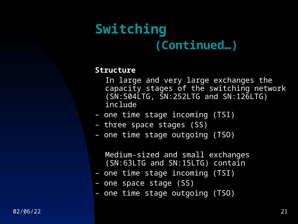
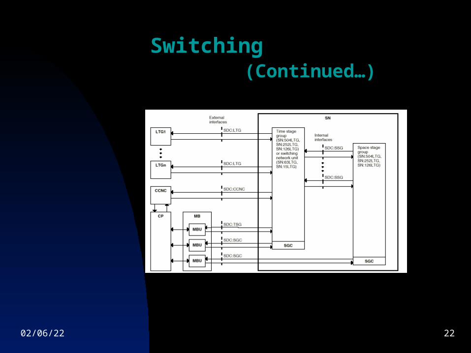
Switching(Continued…)
StructureIn large and very large exchanges the capacity stages of the switching network (SN:504LTG, SN:252LTG and SN:126LTG) include
– one time stage incoming (TSI)– three space stages (SS)– one time stage outgoing (TSO)
Medium-sized and small exchanges (SN:63LTG and SN:15LTG) contain
– one time stage incoming (TSI)– one space stage (SS)– one time stage outgoing (TSO)
04/08/23 22
Switching(Continued…)
04/08/23 23
Access
This includes:
Line / Trunk Group (LTG) Digital Line Unit (DLU) Digital Announcement System
(DAS
04/08/23 24
AccessLine/Trunk Group (LTG)
The line/trunk group (LTG) forms the interface between the digital environment of the node and the digital switching network (SN). The LTGs perform non-central control functions and thus relieve the coordination processor (CP) of routine work.
Several LTG types are available for optimal implementation of the various line types and signaling methods. The two main types of LTGs (differing in their functionality) used are:
LTG-B LTG-C
04/08/23 25
AccessLine/Trunk Group (LTG)
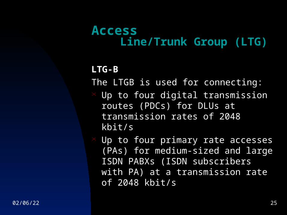
LTG-B
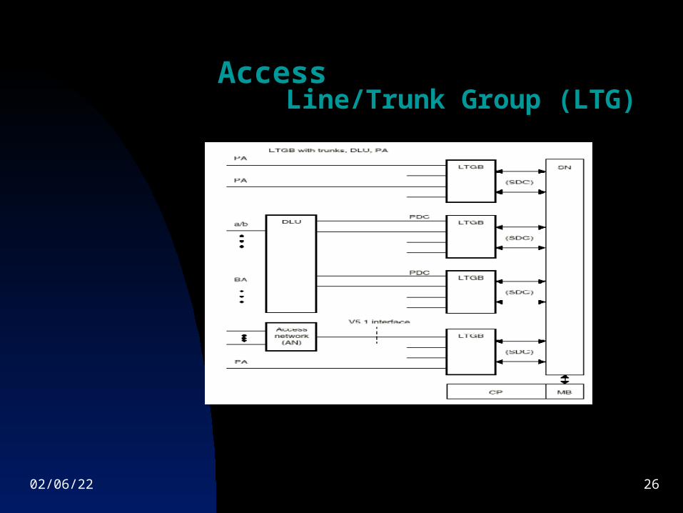
The LTGB is used for connecting: Up to four digital transmission routes
(PDCs) for DLUs at transmission rates of 2048 kbit/s
Up to four primary rate accesses (PAs) for medium-sized and large ISDN PABXs (ISDN subscribers with PA) at a transmission rate of 2048 kbit/s
04/08/23 26
AccessLine/Trunk Group (LTG)
04/08/23 27
AccessLine/Trunk Group (LTG)
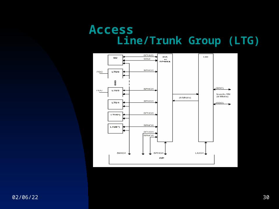
Main Components of an LTG-B
Group processor (GP) Link interface unit between line/trunk group
and switching network (LIU) Group switch (GS) Speech multiplexer (SPMXA) Signaling unit (SU) Line/trunk unit (LTU)
04/08/23 28
AccessLine/Trunk Group (LTG)
Group processor (GP): The group processor (GP) converts the incoming information from outside the network node into the intra-system message format and controls the functional units of the LTG.
Link interface unit between line/trunk group and
switching network (LIU): The link interface unit between line/trunk group and switching network (LIU) connects the LTG to the switching network (SN). The secondary digital carriers (SDC) are connected to the LIU.
Group switch (GS): The group switch (GS) is a
non-blocking time stage controlled by the GP.
04/08/23 29
AccessLine/Trunk Group (LTG
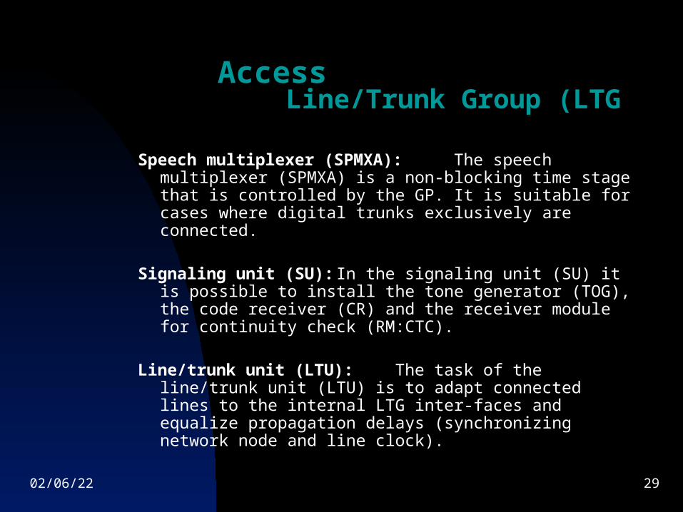
Speech multiplexer (SPMXA): The speech multiplexer (SPMXA) is a non-blocking time stage that is controlled by the GP. It is suitable for cases where digital trunks exclusively are connected.
Signaling unit (SU): In the signaling
unit (SU) it is possible to install the tone generator (TOG), the code receiver (CR) and the receiver module for continuity check (RM:CTC).
Line/trunk unit (LTU): The task of the
line/trunk unit (LTU) is to adapt connected lines to the internal LTG inter-faces and equalize propagation delays (synchronizing network node and line clock).
04/08/23 30
AccessLine/Trunk Group (LTG)
04/08/23 31
AccessLine/Trunk Group (LTG)
Line Trunk Group type-C
The main components of the LTG-C are the same as that of an LTG-B just that there is different software downloaded into this LTG type.
This software is capable of handling different kinds of signaling over the trunks.
04/08/23 32
AccessLine/Trunk Group (LTG)
Important functions of the LTG-C 1. Receiving and evaluating signals from the trunk2. Transmitting signals3. Transmitting messages to the CP and receiving commands from the
CP4. Transmitting audible tones5. Sending and receiving reports to/from the group processors (GP) of
other LTG6. Sending & receiving orders to/from the CCNC7. Adapting line conditions to the 8-Mbit/s standard interface to the
redundant SN8. Through-connecting messages and user information
04/08/23 33
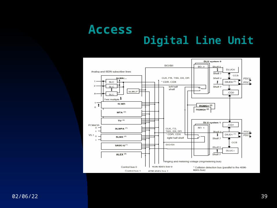
AccessDigital Line Unit
A digital line unit (DLU) can be used to connect subscriber lines and PBX access lines.
The DLU can be operated either locally, or remotely in the network node.
04/08/23 34
AccessDigital Line Unit
DLU Control
The control for DLU (DLUC) controls internal DLU functional sequences and distributes or concentrates signaling flows to and from the line circuits.
To ensure reliability and to increase throughput, the DLU contains two DLUCs.
They work independently of each other in task-sharing mode, so that the second DLUC can take control of all tasks if the first fails.
04/08/23 35
AccessDigital Line Unit
DLU Digital Interface
Digital interface unit for DLU (DIUD) has two interfaces for connecting two PCM30 highways or primary digital carriers (PDC).
The PDCs link the DLU with LTGB. Balanced-pair or coaxial cables can be connected.
04/08/23 36
AccessDigital Line Unit
Bus Distributor and Central Clock Generator
The two clock generators (…CG) operate on the master/slave principle.
Under normal conditions, the clock generator designated as the master is active while the slave generator is on standby.
The master supplies clock signals to both DLU systems. If the master should fail, the slave is activated and takes over the supply of clock signals to both DLU systems.
04/08/23 37
AccessDigital Line Unit
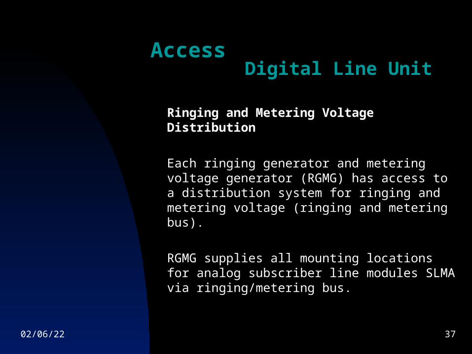
Ringing and Metering Voltage Distribution
Each ringing generator and metering voltage generator (RGMG) has access to a distribution system for ringing and metering voltage (ringing and metering bus).
RGMG supplies all mounting locations for analog subscriber line modules SLMA via ringing/metering bus.
04/08/23 38
AccessDigital Line Unit
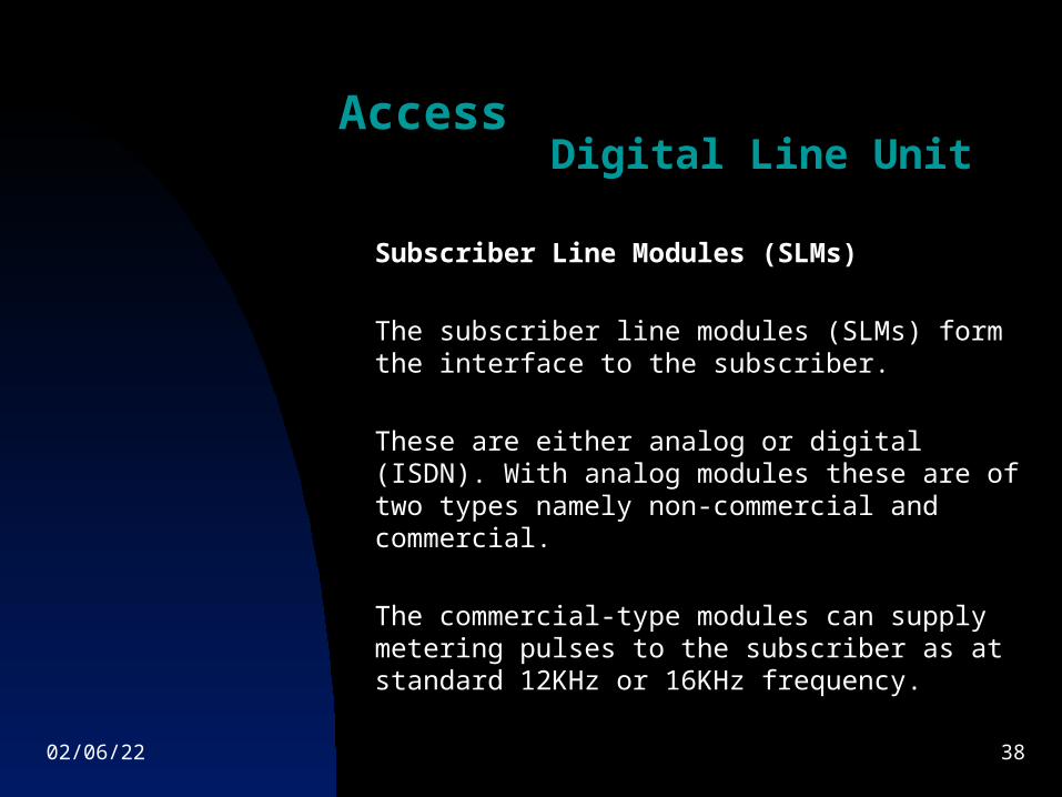
Subscriber Line Modules (SLMs)
The subscriber line modules (SLMs) form the interface to the subscriber.
These are either analog or digital (ISDN). With analog modules these are of two types namely non-commercial and commercial.
The commercial-type modules can supply metering pulses to the subscriber as at standard 12KHz or 16KHz frequency.
04/08/23 39
AccessDigital Line Unit
04/08/23 40
AccessDigital Announcement System
04/08/23 41
Signaling
The EWSD digital electronic switching system can control connections to and from other network nodes using all the common signaling systems.
The signaling functions in an EWSD network-node are handled by the "common channel signaling network control (CCNC)".
04/08/23 42
Signaling
One system that is particularly suitable for stored-program-controlled digital nodes is signaling system no. 7.
This transports signaling information separately from the user information (voice, data) on common-channel signaling links.
04/08/23 43
Signaling
Advantages Higher speed signaling Very reliable signal transmission Flexibility to adapt to future
requirements
04/08/23 44
Signaling
Suitable transmission Medium Copper Wires Optical Fibers Digital Radio Links Satellite links
04/08/23 45
Signaling
Two Kinds of Nodes existing within a No.7 signaling network:
Signaling Point (SP) Signaling Transfer Point (STP)

04/08/23 46

04/08/23 47


