Page 1
129 International Journal of Advances in Arts, Sciences and Engineering, Volume 4 Issue 9 Sep 2016 2320-6144 (Online)
Seismic Analysis and Behaviour Of Different Types Of Rcc Flat Slabs
In Etabs
1. Kolla V Sathya Surya Gowtham 2. K.Vinod Naidu
1.PG Scholar (Structural Engineering), RISE KRISHNA Sai Gandhi Group of Institutions, ONGOLE ,
Andhra Pradesh, India. E-mail id: [email protected]
2. Asst.Professor (Structural Engineering), RISE KRISHNA Sai Gandhi Group of Institutions,
ONGOLE , Andhra Pradesh, India. E-mail id: [email protected]
ABSTRACT:
The flat slab system is currently widely used in construction. It permits flexibility in architecture, more clear
space, low building height, easier formwork, and shorter construction time. However, Flat slab building
structures are significantly more flexible than traditional concrete structures as beams are not present. They are
becoming more vulnerable to earthquakes. The objective of this paper is to investigate the behavior of flat slab in
4 different cases as I). flat slab structure without drop, II). Flat slab structure with column drop, III). Flat slab
structure with shear wall, IV). Flat slab structure with column drop and shear wall together, through response
spectrum method, by using ETABS software. The behavior of the flat slab is investigated in terms of story
displacements, frequency, base shear, story level accelerations. And also most severe problem in flat slabs is
punching shear failure. During the earthquake, unbalanced moments can produce significant shear stresses that
causes slab column connections to brittle punching shear failure. This paper also investigates on which type of
combination produces less punching shear at slab column joint. In this paper we are providing the Zone(Z) –III
and the type of soil Medium.
Keywords: Flat slab, shear wall, Behavior, Response spectrum method, punching shear,ETABS
1. INTRODUCTION
Common practice of design and construction
is to support the slab by beam and beams by
column. This may be called as beam-column
construction. But the beam reduces the
accessible net clear ceiling height. The
aesthetically this type of construction is poor
however performance of those structures are
great. In recent practice slabs are directly put
on the column for aesthetic and architectural
point of view. The load transmission way
changes as a result of deletion of columns.
Regardless, the security of those building is to
be checked. Seismic codes are moreover quiet
on the framework of Flat slab. But from the
past history it can be understood that the Flat
slab is extremely vulnerable in earthquake
point of view. Keeping failure in mind the
behavior of Flat slab building is analyzed
using Response spectrum method.
1.2 ABOUT FLAT SLABS
Flat slab construction is a developing
technology in India. A slab constructed
without supporting beams resting directly
on columns, such slab is called Flat slab.
DROP
Provision of thickened portion of slab
around column is called drop panel.
Drops are provided,
1.To increase the stiffness of slab
Page 2
130 International Journal of Advances in Arts, Sciences and Engineering, Volume 4 Issue 9 Sep 2016 2320-6144 (Online)
2. To increase shear strength of slab-column joint.
3.To increase negative moment caring capacity in
the slab column connections.
Column Capital
These are flared profile around column as
shown in Fig 1.3 Column heads are provided,
1. To increase the perimeter of critical section
for shear.
2. To provide more supporting area.
Slabs of constant thickness which do not have
drop panels or column capitals arecalled as Flat
plates. The strength of the Flat plate structure is
often limited due to punching shear action
around columns. So they are predominantly
used in low seismic areas.
Edge beam
Flat slabs may also provide with edge beams or
a perimeter beam, which increase the stiffness
of discontinuous edge, and also increases, shear
capacity at exterior column supports.
1.3 TYPES OF FLAT SLABS
1. Flat plate system
2. Flat slab with column capital only
3. Flat slab with column drop only
4. Flat slab with column capital and column
drop together
1.4 FAILURE MODES OF FLAT SLABS:
It is very important to thoroughly check the
safety of Flat plates and Flat slabs in shear. In
past most of failures have been reported due to
improper design for shear transfer, especially
at the exterior columns. This is due to
inadequate appreciation of shear forces in Flat
slabs and bending moment produced in
external columns.
1.5 One Way Shear or Beam Shear:
The critical section for two way shear is at a
distance equal to the effective depth from the
face of column and edge of drop.
1.6 Two Way Shear or Punching Shear
Failure:
When a large concentrated load is applied on a
small area, there is a possibility of a ‘punch
through’ type of shear failure. Similarly when
Flat plates or Flat slabs rests on columns and
subjected to gravity loading then they
consequently undergoes two way bending. At
this time the reaction to the loading on the slab
is concentrated on a relatively small area, and if
thickness of slab is not adequate in this area,
shear failure may occur by punching through of
the reaction area along pyramid or a truncated
cone. This type of failure is called as Punching
shear or Two way shear.
1.7 ADVANTAGES OF FLAT SLABS
Flat slab buildings have the following
advantages over the conventional buildings.
1. The ease of construction of formwork.
2. It provides large clear ceiling height.
3. The plain ceiling gives an attractive and
pleasing appearance.
4. In absence of beams provision of acoustical
treatment is easy.
5. Due to the elimination of beam height in
multi storey structures, there will be a reduction
of one storey height for every six story’s.
6. The free space for air pipes, water, etc
between slab and a possible furred ceiling.
7. Seismic weight of the building reduces due
to absent of beams
8. In order to reduce the thickness of flat slab in
long spans, prestressing gives cost effective
9. Flexibility in wall partitions, and layout of
plan.
1.8 DISADVANTAGES OF FLAT SLABS
1. Stiffness of Flat slab system is less compared
to slab-beam-column system. This result in
significant bending moments due to horizontal
loads cannot be effectively transferred in
structure. For this reason Flat slab is used in low
rise and medium rise buildings, which are not
tall enough to be subjected to large lateral loads.
2. Serviceability problems arise with excessive
long term deflections of such relatively thin
slabs. However they are not so serious if
column capitals or drops are provided.
2.LITERATURE REVIEW
Padma Gome , Shruti Ratnaparkhe ,Dr.
Uttamasha Gupta1(2012)Seismic
Behaviour of Buildings Having Flat Slabs with
Drops(International journal of emerging
technology and advanced engineering)
The object of the present work is to compare the
behaviour of multi-storey buildings having Flat
slabs with drops with that of having two way
slabs with beams and to study the effect of part
Page 3
131 International Journal of Advances in Arts, Sciences and Engineering, Volume 4 Issue 9 Sep 2016 2320-6144 (Online)
shear walls on the performance of these two
types of buildings under seismic forces. Present
work provides a good source of information on
the parameters lateral displacement and storey
drift.
For that large plan and short plans of 7,9,
11storeys are assumed and analyzed in zone III,
zone IV and zoneV. Use of Flat slabs with drop
instead of conventional building results in
increase in drift values in shorter plans and
decrease in larger plans, marginally in a range
of 0.5mm to 3mm. Still all drift values are
within permissible limits even without shear
walls. In zone III and IV use of Flat slabs with
drop in place of beam slab arrangements,
though, alters the maximum lateral
displacement values, however, these all are
well within permissible limits, even without
shear walls. Provision of part shear walls in
zone V is not enough to keep maximum
displacements within permissible limits,
whether it is a beam slab framed structure or
framed structure with flat slabs with drop.
Replacement of beam slab arrangement by Flat
slabs with drop results in increase in column
reinforcement, however, presence of shear
walls compensates the increment resulted, but
in larger plans only in all the zones.
Amit A. Sathawane & R.S. Deotale (2012)
Analysis And Design of Flat Slab And Grid
Slab And Their Cost Comparison
(International journal of engineering
research and applications).
Flat-slab building structure is widely used due
to the many advantages it possesses over
conventional moment-resisting frames. These
are generally used with column head and
column drops. Grid floor systems beams are
spaced at regular intervals in perpendicular
directions, and also monolithic with slab. These
are generally used for architectural reasons for
large rooms such as vestibules, theatre 15 halls,
auditoriums, show rooms of shops where
column free space is often the main
requirement. The objective of this project is to
determine the most economical slab between
Flat slab without drop, Flat slab with drop and
grid slab. The total width is 27.22 m and length
of slab is 31.38m. Total area of slab is 854.16
sqm.It concludes that the flat slab with drop is
more economical than Flat slab without drop
and Grid slabs.
Results show that concrete required in grid
slabs is more when compared to Flat slab with
drop and Flat slab without drop. And also Steel
required in Flat slab without drop is more as
compared to steel required in Flat slab with
drop and grid slab.
3. MODELING AND ANALYSIS OF 6
STOREY OFFICE BUILDING
Grade of concrete = 25
Grade of steel = Fe 415
Slab Thickness = 0.260m
Number of stories = (6) G+5
Number of bays along X-direction =4
Number of bays along Y-direction = 5
Storey Height = 3.2 meters
Bay width along X- direction =8m
Bay width along Y-direction = 8m
Column size = 0.7x0.7m
Edge Beam size = 0.3x0.23m
Drop size = 3.0x 3.0m
Slab Thickness at drop = 0.325m
Shear wall thickness = 0.2 m
Loading Specifications: Wall load for the outer side = 14KN/m
Wall load for the inner side = 9 KN/m
Wall load for the terrace = 4 KN/m
Dead load of slab = 6.5 KN/m2
Page 4
132 International Journal of Advances in Arts, Sciences and Engineering, Volume 4 Issue 9 Sep 2016 2320-6144 (Online)
Live load = 4 KN/m2
Earth quake load for the building has been
calculated as per IS-18983:2002
i. Zone (Z) = III
ii Soil = Medium
iii Response Reduction Factor (RF) =5
iv Importance Factor = 1
v Damping Ratio = 0.05
For Seismic loading only 50% of the
imposed load is considered.
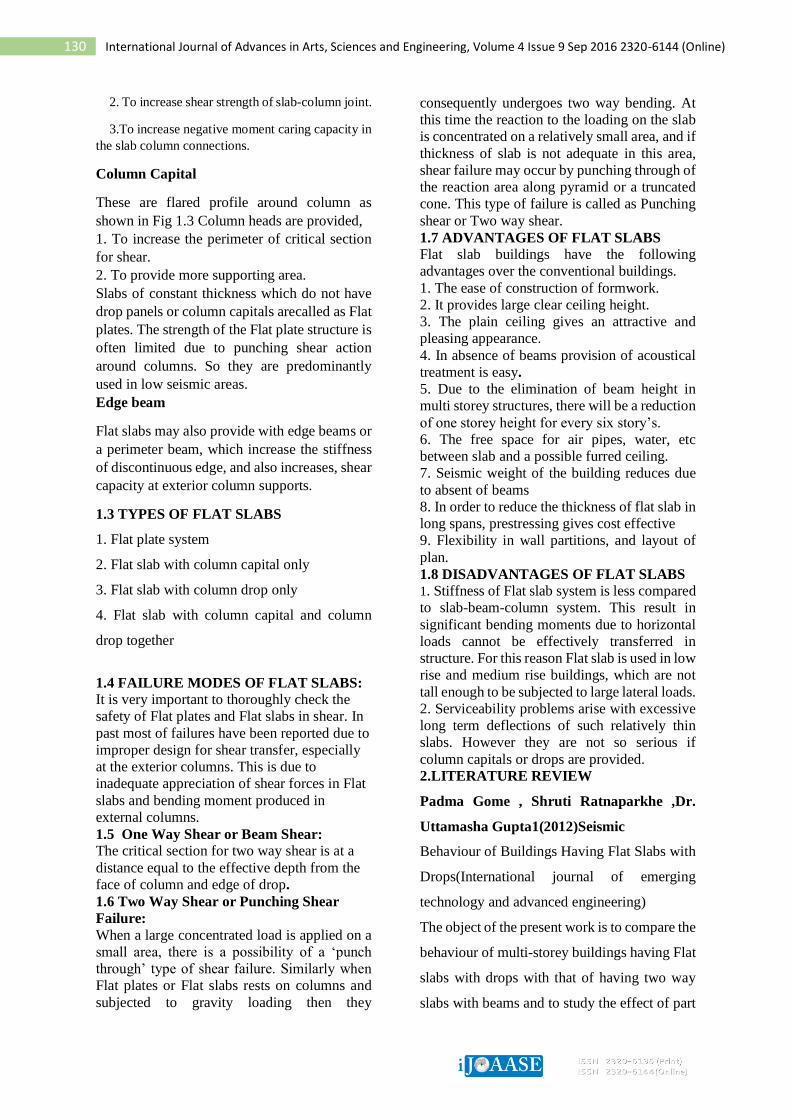
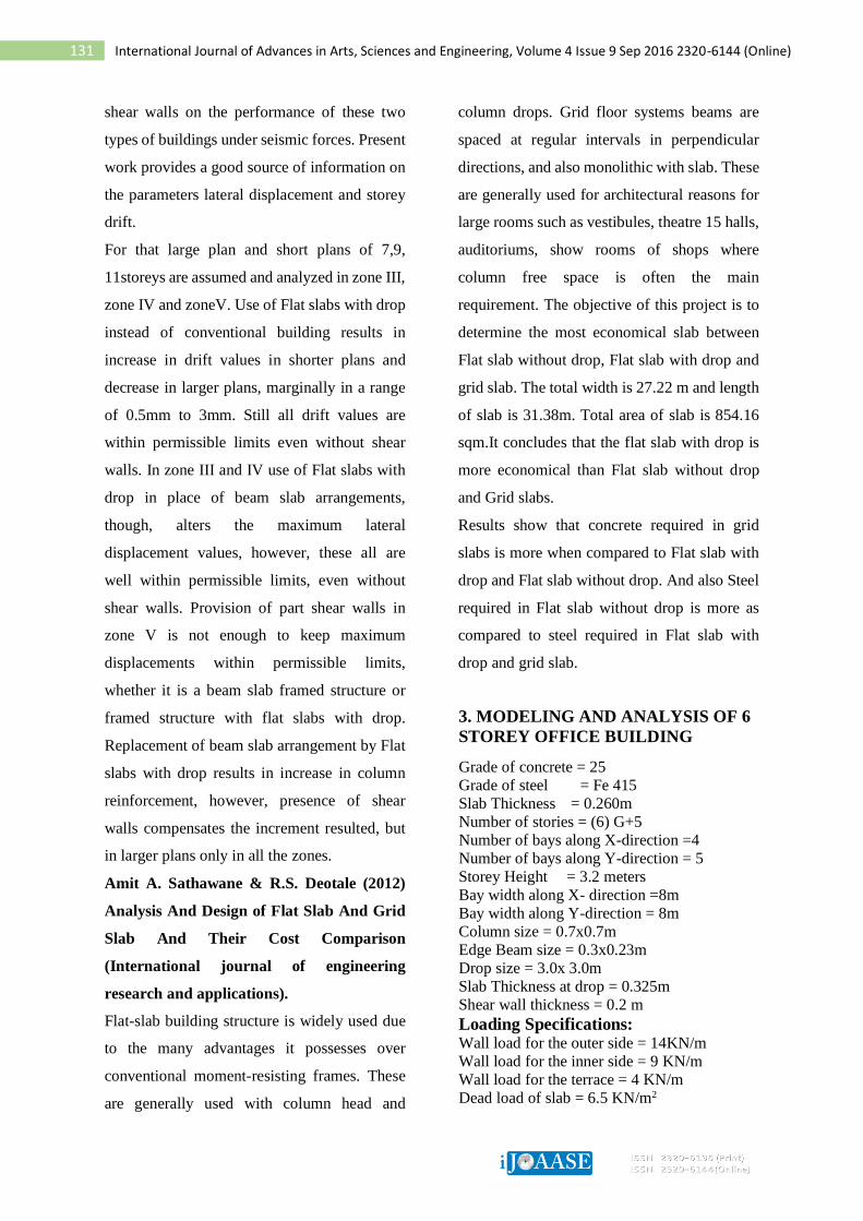
Fig. 1: Working plan
Fig. 2: Model 1(Flat slab structure
without drop)
Fig 3: Model 2(Flat slab structure with
column drop only)
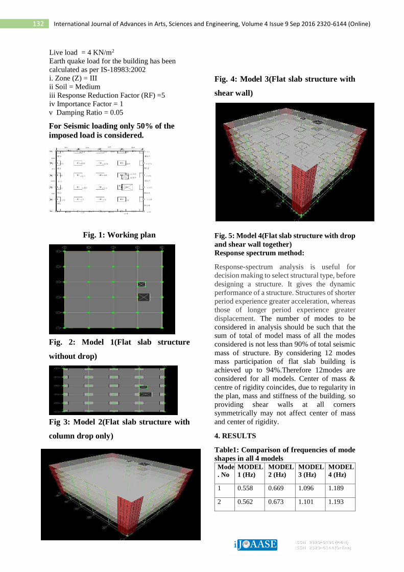
Fig. 4: Model 3(Flat slab structure with
shear wall)
Fig. 5: Model 4(Flat slab structure with drop
and shear wall together)
Response spectrum method:
Response-spectrum analysis is useful for
decision making to select structural type, before
designing a structure. It gives the dynamic
performance of a structure. Structures of shorter
period experience greater acceleration, whereas
those of longer period experience greater
displacement. The number of modes to be
considered in analysis should be such that the
sum of total of model mass of all the modes
considered is not less than 90% of total seismic
mass of structure. By considering 12 modes
mass participation of flat slab building is
achieved up to 94%.Therefore 12modes are
considered for all models. Center of mass &
centre of rigidity coincides, due to regularity in
the plan, mass and stiffness of the building. so
providing shear walls at all corners
symmetrically may not affect center of mass
and center of rigidity.
4. RESULTS
Table1: Comparison of frequencies of mode
shapes in all 4 models Mode
. No
MODEL
1 (Hz)
MODEL
2 (Hz)
MODEL
3 (Hz)
MODEL
4 (Hz)
1 0.558 0.669 1.096 1.189
2 0.562 0.673 1.101 1.193
Page 5
133 International Journal of Advances in Arts, Sciences and Engineering, Volume 4 Issue 9 Sep 2016 2320-6144 (Online)
3 0.616 0.707 1.923 1.985
4 1.956 2.262 4.503 4.656
5 1.969 2.277 4.51 4.662
6 2.153 2.403 5.401 6.233
7 4.126 4.545 5.487 6.358
8 4.144 4.566 5.54 6.404
9 4.532 4.854 5.601 6.442
10 5.386 6.211 5.705 6.568
11 5.476 6.369 5.721 6.588
12 5.513 6.369 5.788 6.666
Graph 1: Graph for fundamental mode of
frequencies
Graph 2: Graph for fundamental time
period
Table 2: comparison of design storey shear
in all 4 models
Heigh
t of
buildi
ng Story
MODE
L1
MODE
L2
MODE
L3
MODE
L4
(m) (KN) (KN) (KN) (KN)
2.1
PLINT
H 1164.53 1412.03 2194.68 2405.98
5.6
STOR
Y1 1163.58 1410.9 2193.15 2404.32
8.8
STOR
Y2 1133.17 1374.32 2135.56 2341.74
12
STOR
Y3 1058.17 1284.14 1993.87 2187.75
15.2
STOR
Y4 918.77 1116.53 1730.55 1901.58
18.4
STOR
Y5 695.25 847.75 1308.3 1442.68
21.6
STOR
Y6 367.7 453.88 689.55 770.21
Graph 3: Graph shown for storey shear in
all 4 models
Table 3: Comparison of storey
displacements in x-direction in 4 models
Story MODEL1 MODEL2 MODEL3 MODEL4
(mm) (mm) (mm) (mm)
STORY1 3.1 3 1.1 1.1
STORY2 5.7 5.2 2.2 2.1
STORY3 8.1 7.1 3.5 3.3
STORY4 10.2 8.7 4.8 4.5
STORY5 11.8 9.9 6 5.6
STORY6 13.1 10.7 7.2 6.6
Graph 4: Graph shown for comparison of
storey displacements in y-direction in all
4models
PUNCHING SHEAR FAILURE IN FLAT
SLAB BUILDINGS
0
0.2
0.4
0.6
0.8
1
1.2
1.4
MODEL 1(Hz)
MODEL 2(Hz)
MODEL 3(Hz)
MODEL 4(Hz)
FUNDAMENTAL MODE OF FREQUENCY
fundamental mode offrequency
0
0.2
0.4
0.6
0.8
1
1.2
1.4
1.6
1.8
2
MODEL 1 MODEL 2 MODEL 3 MODEL 4
FUNDAMENTAL TIME PERIOD
FUNDAMENTAL TIME PERIOD
0
500
1000
1500
2000
2500
3000
1 2 3 4 5 6 7
s
t
o
r
e
y
s
h
e
a
r storey no
storey shears
Storey
MODEL 1
MODEL 2
MODEL 3
MODEL 4
0
2
4
6
8
10
12
14
1 2 3 4 5 6
D
i
s
p
l
a
c
e
m
e
n
t
s
(
m
m)
Storey no
Storey Displacements (mm)
Storey
MODEL 1
MODEL 2
MODEL 3
MODEL 4
Page 6
134 International Journal of Advances in Arts, Sciences and Engineering, Volume 4 Issue 9 Sep 2016 2320-6144 (Online)
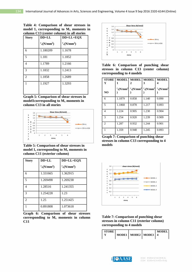
Table 4: Comparison of shear stresses in
model 1, corresponding to Mx moments in
column C13 (center column) in all stories
Story DD+LL DD+LL+EQX
τv(N/mm2) τ
v(N/mm2)
6 1.180209 1.1678
5 1.181 1.1852
4 1.1789 1.2166
3 1.1832 1.2413
2 1.1858 1.2689
1 1.1927 1.3293
Graph 5: Comparison of shear stresses in
model1corresponding to Mx moments in
column C13 in all stories
Table 5: Comparison of shear stresses in
model 1, corresponding to Mx moments in
column C11 (exterior column)
Story DD+LL DD+LL+EQX
τv(N/mm2) τ
v(N/mm2)
6 1.331665 1.362915
5 1.269498 1.269238
4 1.28516 1.241355
3 1.254228 1.23
2 1.25 1.251425
1 0.891808 1.073618
Graph 6: Comparison of shear stresses
corresponding to Mx moments in column
C11
Table 6: Comparison of punching shear
stresses in column C13 (center column)
corresponding to 4 models
STORE
Y
MODEL
1
MODEL
2
MODEL
3
MODEL
4
NO
τv(N/mm2
)
τv(N/mm2
)
τv(N/mm2
)
τv(N/mm2
)
6 1.1879 0.858 1.140 0.890
5 1.1868 0.878 1.217 0.893
4 1.224 0.905 1.230 0.904
3 1.254 0.920 1.239 0.909
2 1.287 0.932 1.244 0.901
1 1.359 0.948 1.245 0.893
Graph 7: Comparison of punching shear
stresses in column C13 corresponding to 4
models
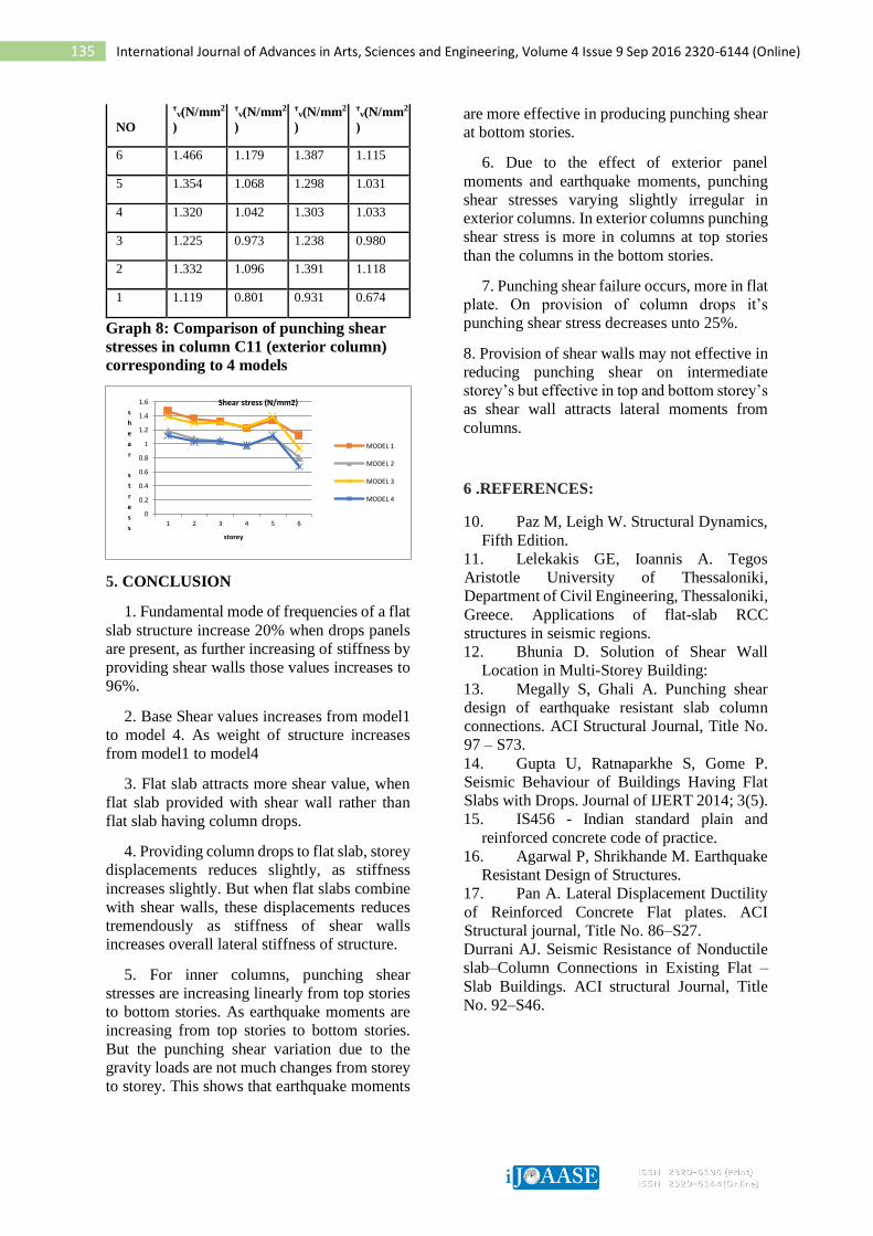
Table 7: Comparison of punching shear
stresses in column C11 (exterior column)
corresponding to 4 models
STORE
Y MODE1 MODE2 MODE3
MODEL
4
0
0.2
0.4
0.6
0.8
1
1.2
1.4
1.6
1 2 3 4 5 6
S
h
e
a
r
s
t
r
e
s
s(
N
/
m
m
2)
storey
Shear Stres (N/mm2)
DD+LL
DD+LL+EQX
0
0.2
0.4
0.6
0.8
1
1.2
1.4
1.6
1 2 3 4 5 6
S
h
e
a
r
s
t
r
e
s
s(
N
/
m
m
2)
storey
Shear Stres (N/mm2)
DD+LL
DD+LL+EQX
0
0.2
0.4
0.6
0.8
1
1.2
1.4
1.6
1 2 3 4 5 6
s
h
e
a
r
s
t
r
e
s
s
storey
shear stress (N/mm2)
MODEL 1
MODEL 2
MODEL 3
MODEL 4
Page 7
135 International Journal of Advances in Arts, Sciences and Engineering, Volume 4 Issue 9 Sep 2016 2320-6144 (Online)
NO
τv(N/mm2
)
τv(N/mm2
)
τv(N/mm2
)
τv(N/mm2
)
6 1.466 1.179 1.387 1.115
5 1.354 1.068 1.298 1.031
4 1.320 1.042 1.303 1.033
3 1.225 0.973 1.238 0.980
2 1.332 1.096 1.391 1.118
1 1.119 0.801 0.931 0.674
Graph 8: Comparison of punching shear
stresses in column C11 (exterior column)
corresponding to 4 models
5. CONCLUSION
1. Fundamental mode of frequencies of a flat
slab structure increase 20% when drops panels
are present, as further increasing of stiffness by
providing shear walls those values increases to
96%.
2. Base Shear values increases from model1
to model 4. As weight of structure increases
from model1 to model4
3. Flat slab attracts more shear value, when
flat slab provided with shear wall rather than
flat slab having column drops.
4. Providing column drops to flat slab, storey
displacements reduces slightly, as stiffness
increases slightly. But when flat slabs combine
with shear walls, these displacements reduces
tremendously as stiffness of shear walls
increases overall lateral stiffness of structure.
5. For inner columns, punching shear
stresses are increasing linearly from top stories
to bottom stories. As earthquake moments are
increasing from top stories to bottom stories.
But the punching shear variation due to the
gravity loads are not much changes from storey
to storey. This shows that earthquake moments
are more effective in producing punching shear
at bottom stories.
6. Due to the effect of exterior panel
moments and earthquake moments, punching
shear stresses varying slightly irregular in
exterior columns. In exterior columns punching
shear stress is more in columns at top stories
than the columns in the bottom stories.
7. Punching shear failure occurs, more in flat
plate. On provision of column drops it’s
punching shear stress decreases unto 25%.
8. Provision of shear walls may not effective in
reducing punching shear on intermediate
storey’s but effective in top and bottom storey’s
as shear wall attracts lateral moments from
columns.
6 .REFERENCES:
10. Paz M, Leigh W. Structural Dynamics,
Fifth Edition.
11. Lelekakis GE, Ioannis A. Tegos
Aristotle University of Thessaloniki,
Department of Civil Engineering, Thessaloniki,
Greece. Applications of flat-slab RCC
structures in seismic regions.
12. Bhunia D. Solution of Shear Wall
Location in Multi-Storey Building:
13. Megally S, Ghali A. Punching shear
design of earthquake resistant slab column
connections. ACI Structural Journal, Title No.
97 – S73.
14. Gupta U, Ratnaparkhe S, Gome P.
Seismic Behaviour of Buildings Having Flat
Slabs with Drops. Journal of IJERT 2014; 3(5).
15. IS456 - Indian standard plain and
reinforced concrete code of practice.
16. Agarwal P, Shrikhande M. Earthquake
Resistant Design of Structures.
17. Pan A. Lateral Displacement Ductility
of Reinforced Concrete Flat plates. ACI
Structural journal, Title No. 86–S27.
Durrani AJ. Seismic Resistance of Nonductile
slab–Column Connections in Existing Flat –
Slab Buildings. ACI structural Journal, Title
No. 92–S46.
0
0.2
0.4
0.6
0.8
1
1.2
1.4
1.6
1 2 3 4 5 6
s
h
e
a
r
s
t
r
e
s
sstorey
Shear stress (N/mm2)
MODEL 1
MODEL 2
MODEL 3
MODEL 4