University for Business and Technology in Kosovo University for Business and Technology in Kosovo UBT Knowledge Center UBT Knowledge Center UBT International Conference 2014 UBT International Conference Nov 7th, 3:45 PM - 4:00 PM Seismic analysis of structural building with reinforced concrete Seismic analysis of structural building with reinforced concrete shear walls according to the European Standards shear walls according to the European Standards Armend Mujaj Polytechnic University of Tirana, [email protected]Florim Grajçevci Polytechnic University of Tirana, fl[email protected]Driton R. Kryeziu Polytechnic University of Tirana, [email protected]Follow this and additional works at: https://knowledgecenter.ubt-uni.net/conference Part of the Architecture Commons Recommended Citation Recommended Citation Mujaj, Armend; Grajçevci, Florim; and Kryeziu, Driton R., "Seismic analysis of structural building with reinforced concrete shear walls according to the European Standards" (2014). UBT International Conference. 4. https://knowledgecenter.ubt-uni.net/conference/2014/all-events/4 This Event is brought to you for free and open access by the Publication and Journals at UBT Knowledge Center. It has been accepted for inclusion in UBT International Conference by an authorized administrator of UBT Knowledge Center. For more information, please contact [email protected].
Transcript
University for Business and Technology in Kosovo University for Business and Technology in Kosovo
UBT Knowledge Center UBT Knowledge Center
UBT International Conference 2014 UBT International Conference
Nov 7th, 3:45 PM - 4:00 PM
Seismic analysis of structural building with reinforced concrete Seismic analysis of structural building with reinforced concrete
shear walls according to the European Standards shear walls according to the European Standards
Florim Grajçevci Polytechnic University of Tirana, [email protected]
Driton R. Kryeziu Polytechnic University of Tirana, [email protected]
Follow this and additional works at: https://knowledgecenter.ubt-uni.net/conference
Part of the Architecture Commons
Recommended Citation Recommended Citation Mujaj, Armend; Grajçevci, Florim; and Kryeziu, Driton R., "Seismic analysis of structural building with reinforced concrete shear walls according to the European Standards" (2014). UBT International Conference. 4. https://knowledgecenter.ubt-uni.net/conference/2014/all-events/4
This Event is brought to you for free and open access by the Publication and Journals at UBT Knowledge Center. It has been accepted for inclusion in UBT International Conference by an authorized administrator of UBT Knowledge Center. For more information, please contact [email protected].
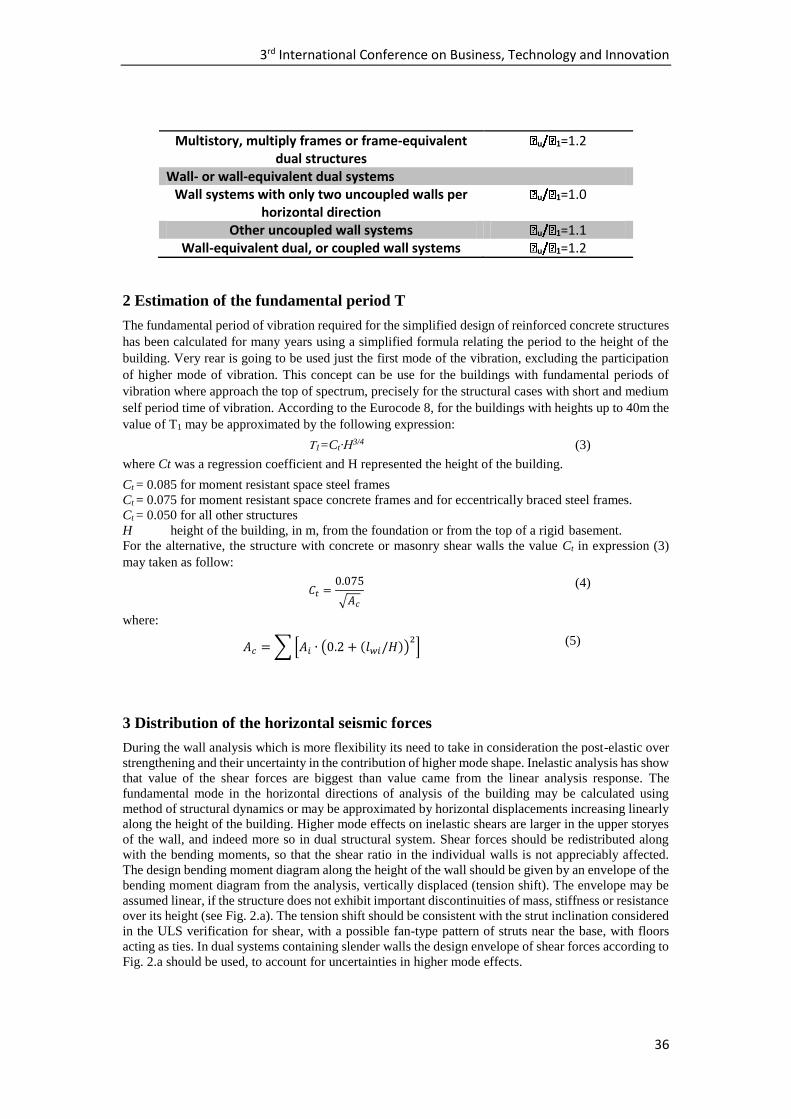
3rd International Conference on Business, Technology and Innovation
44
Table 7. Seismic forces and following parameters
Direction unit X-X Y-Y
building weight [kN] 59594,625 59594,625
base acceleration ag [m/s2] 0.25g 0,25g fundamental period Tc [s] 1.0739 1.0271 behavior factor no 3.00 3.00 spectral type no B B spectral ordinate no 0.1164 0.1217 coefficient λ no 0.85 0.85 factor importance γI
no 1.00 1.00 base seismic forces [kN] 5896.30 6164.76
Table 8: Distribution of seismic force on the floors of the structure in the direction x-x
levelZi
(m)
Wi
(kN)
WiZi
(kNm)
Fb
(kN)
Fi
(kN)
11 33 4577.13 151045.13 6164.76 879.42
10 30 5501.75 165052.50 6164.76 960.97
9 27 5501.75 148547.25 6164.76 864.87
8 24 5501.75 132042.00 6164.76 768.78
7 21 5501.75 115536.75 6164.76 672.68
6 18 5501.75 99031.50 6164.76 576.58
5 15 5501.75 82526.25 6164.76 480.49
4 12 5501.75 66021.00 6164.76 384.39
3 9 5501.75 49515.75 6164.76 288.29
2 6 5501.75 33010.50 6164.76 192.19
1 3 5501.75 16505.25 6164.76 96.10
sum 59594.63 1058833.88 6164.76
Table 9: Distribution of seismic force on the floors of the structure in the direction y-y
level Zi (m) Wi (kN) WiZi (kNm) Fb (kN) Fi (kN)
11 33 4577.13 151045.13 5896.30 841.12
10 30 5501.75 165052.50 5896.30 919.12
9 27 5501.75 148547.25 5896.30 827.21
8 24 5501.75 132042.00 5896.30 735.30
7 21 5501.75 115536.75 5896.30 643.39
6 18 5501.75 99031.50 5896.30 551.47
5 15 5501.75 82526.25 5896.30 459.56
4 12 5501.75 66021.00 5896.30 367.65
3 9 5501.75 49515.75 5896.30 275.74
2 6 5501.75 33010.50 5896.30 183.82
1 3 5501.75 16505.25 5896.30 91.91
Sum 59594.63 1058833.88 5896.30
Shear strengthening control
During the analysis of the structural members and also the completely/assembly of the structure it is
important to mentioned that the effect of second theory has direct impact on the chosen methodology
for structural analysis, the structure with non moveable joints and moveable joints. it is non that the
structural analysis of the elements in this method it is based in deform element. For the request of the
structure for non moveable joints, according to the EC-2 need to be satisfy the condition in variety of
the floor numbering as follow:
6,040,01065625,47
69869,2533α
7x
(30)
Architecture, Spatial Planning and Civil Engineering
45
6,0344,0103062,64
69869,2533α
7y
(31)
6,0233,038,112
02,23
103,053905
69869,2533985,0α 2
2
7T
(32)
From the above calculations it is seen that the required condition for "structure with non moveable
joints" for the structural analysis it is satisfy, and also the structural stability on torsion.
Design Shear force Vsd (kN) 1007,25 Behavior factor (q) 3,0 Spectral ordinate Sd (T1) 0,1164 Spectral ordinate Sd (Tc) 0,25 Value of factor (Ɛ) 2,41 Design value of shear forces Vsd* (kN) 2427,50 Critical value of the zone - wall (m) 5,50 Shear design capacity Vrd2 in critical zone (kN)
4313,36
Shear design capacity Vrd2 in noncritical zone (kN)
5391,70
Value of truss pressure diagonal VRd3 (kN) 3264,68
Ductility control
bw (cm) 25,0 lcr. (cm) 75,0 bo (cm) 20,0 ho (cm) 72,5 vd 0,1637
Internal desssign bending moment, internal shear and axial forces for M5
length (cm)
thickness (cm)
Msd (kN·m)
Vsd (kN)
Nsd
(kN) Msds (kN·m)
500 25 22876,30 1007,25 -3411,25 30551,613
Architecture, Spatial Planning and Civil Engineering
47
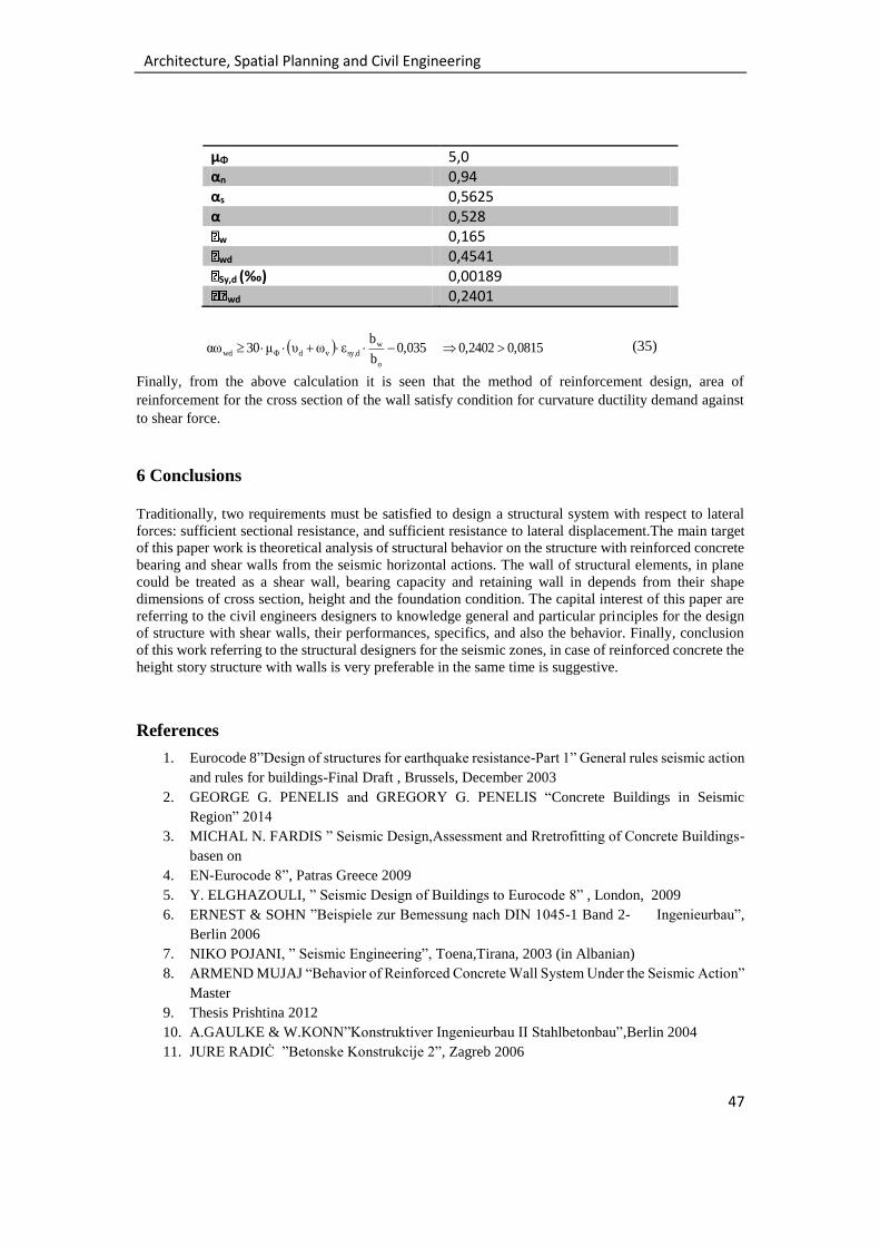
μΦ 5,0 αn 0,94 αs 0,5625 α 0,528
w 0,165
wd 0,4541
Sy,d (‰) 0,00189
wd 0,2401
0,08150,24020,035b
bεωυμ30αω
o
wdsy,vdΦwd (35)
Finally, from the above calculation it is seen that the method of reinforcement design, area of
reinforcement for the cross section of the wall satisfy condition for curvature ductility demand against
to shear force.
6 Conclusions
Traditionally, two requirements must be satisfied to design a structural system with respect to lateral
forces: sufficient sectional resistance, and sufficient resistance to lateral displacement.The main target
of this paper work is theoretical analysis of structural behavior on the structure with reinforced concrete
bearing and shear walls from the seismic horizontal actions. The wall of structural elements, in plane
could be treated as a shear wall, bearing capacity and retaining wall in depends from their shape
dimensions of cross section, height and the foundation condition. The capital interest of this paper are
referring to the civil engineers designers to knowledge general and particular principles for the design
of structure with shear walls, their performances, specifics, and also the behavior. Finally, conclusion
of this work referring to the structural designers for the seismic zones, in case of reinforced concrete the
height story structure with walls is very preferable in the same time is suggestive.
References
1. Eurocode 8”Design of structures for earthquake resistance-Part 1” General rules seismic action
and rules for buildings-Final Draft , Brussels, December 2003
2. GEORGE G. PENELIS and GREGORY G. PENELIS “Concrete Buildings in Seismic
Region” 2014
3. MICHAL N. FARDIS ” Seismic Design,Assessment and Rretrofitting of Concrete Buildings-
basen on
4. EN-Eurocode 8”, Patras Greece 2009
5. Y. ELGHAZOULI, ” Seismic Design of Buildings to Eurocode 8” , London, 2009
6. ERNEST & SOHN ”Beispiele zur Bemessung nach DIN 1045-1 Band 2- Ingenieurbau”,
Berlin 2006
7. NIKO POJANI, ” Seismic Engineering”, Toena,Tirana, 2003 (in Albanian)
8. ARMEND MUJAJ “Behavior of Reinforced Concrete Wall System Under the Seismic Action”
Master
9. Thesis Prishtina 2012
10. A.GAULKE & W.KONN”Konstruktiver Ingenieurbau II Stahlbetonbau”,Berlin 2004
11. JURE RADIĊ ”Betonske Konstrukcije 2”, Zagreb 2006
3rd International Conference on Business, Technology and Innovation
48
12. MUSTAFA HRASNICA“ Seizmicka Analiza Zgrada”Sarajevo 2005
13. EMIR HADŹI-MUSIĊ ”Aseizmiċke Konstrukcije u Visokogradnji” Sarajevo 1985
14. ALFONS GORIS, WIRTSCHAFTSING, GERHARD RICHTER und HELMUT
KIRCHNER”
15. Stalbeton und Spannbeton Nach EC 2 Teil 1” Berlin 2000
16. Eurocode 0”Basic of structural design”,2002
17. Eurocodw 1”Action on structures”2002
18. Eurocode 2”Design of concrete structures”2004
19. Autodesk Robot Structural Analysis Professional 2015”