306 SEISMIC CONSIDERATIONS IN THE DESIGN OF CRYOGENIC PRESSURE VESSELS John Webster* ABSTRACT: The author has recently been involved in the analysis of the seismic performance of several standard types of cryogenic pressure vessel which were originally designed in the United States. Particular attention was accorded to the magnitude and distribution of the localised membrane and bending stresses developed in the inner and outer vessels near the points at which the internal and external support systems are attached. The analyses revealed that reinforcement would be required in certain critical areas in order to meet the design rules established by the relevant New Zealand government agency. Suitable modifications were made in these areas, although there seems reason to believe that the design rules may in some respects be unduly conservative. INTRODUCTION: The pressure vessels concerned are cryogenic storage units for liquid oxygen, nitrogen or argon. A typical unit is shown in Figure 1. Each unit comprises an inner pressure vessel which contains the stored material at a temperature between 150 and 200 degrees below zero Celsius. The temperature is maintained by an insulating system which includes a complete evacuated jacket. An outer pressure vessel is therefore required to maintain the vacuum. The inner vessel is connected to the outer vessel through compact supporting members fabricated from steel and rein- forced glass fibre tubes and welded to the end caps via reinforcing plates. The outer vessel is supported on three symmetrically located members, each of which is fabricated from mild steel plate to form a tapered channel section. The salient properties and dimensions are summarised in Table 1. The vessels were designed in accordance with the ASME Boiler and Pressure Vessel Code (1980). The shell material is a mild steel, designation SA 240 Type 304, with an allowable stress equal to 130 MPa. Local stress calculations were required to be carried out in accordance with BS5500 (1982) . is applied. The seismic live load is calculated on the basis that the vessel is filled to capacity with the densest sub- stance which it is designed to contain (liquid argon in the present case). No allowance is permitted for the considerable material strength increase which occurs at cryogenic temperatures. These design rules are particularly stringent, and substantial modifications had to be made to the pressure vessels discussed in this paper in order to achieve the required strength levels. The situation concerning the seismic design of industrial plant is clearly less than satisfactory, and various attempts have been made to develop more logical design rules. On the one hand, Evison and Mowat (1982) have suggested that NZS 4203 should be extended to provide structural type factors and risk factors appropriate to industrial plant, while, on the other hand, Norton, Gillies and Edmonds (1982) have prepared recommendations for the seismic design of petrochemical plant which are based on the selection of an earthquake return period and a direct assessment of the structural displacement ductility. The latter approach appears to the author to have some significant advantages, and the suggested design procedure may use- fully be examined in more detail. SEISMIC DESIGN RULES: As the authority responsible for the approval of pressure vessels in New Zealand, the Marine Division of the Ministry of Transport demand that all cryogenic storage units should comply with NZS 4203. As that standard does not cover indust- rial plant or equipment, this requirement in effect means that such vessels must remain elastic under the design seismic load. In practice, the alternative design method is used and, since the vessels are at least potentially relocatable, a uniform seismic coefficient equal to 0.60 *Senior Lecturer, School of Architecture, Victoria University of Wellington BULLETIN OF THE N E W Z E A L A N D NATIONAL SOCIETY FOR For each seismic zone in New Zealand an elastic response spectrum has been derived for an earthquake with a return period of 150 years. Whether the available data is sufficient to support the zoning system adopted or the corresponding earthquake intensities must remain, to some extent, a matter of opinion, but all the design methods proposed are open to similar doubts. At any rate, the elastic response spectrum constructed for the most critical zone has been adjusted to give the same seismic coefficient for short period structures as NZS 420 3. The seismic performance of a structure is then expressed in terms of a displacement ductility value defined as the ratio between the displacement at some critical point which can be sustained under post-elastic cyclic loading without HQUAKE ENGINEERING, VOL. 16, NO. 4, DECEMBER 1983
Transcript
306
SEISMIC CONSIDERATIONS IN THE DESIGN OF CRYOGENIC PRESSURE VESSELS
John Webster*
ABSTRACT:
The author has recently been involved in the analysis of the seismic performance of several standard types of cryogenic pressure vessel which were originally designed in the United States. Particular attention was accorded to the magnitude and distribution of the localised membrane and bending stresses developed in the inner and outer vessels near the points at which the internal and external support systems are attached. The analyses revealed that reinforcement would be required in certain critical areas in order to meet the design rules established by the relevant New Zealand government agency. Suitable modifications were made in these areas, although there seems reason to believe that the design rules may in some respects be unduly conservative.
INTRODUCTION:
The pressure vessels concerned are cryogenic storage units for liquid oxygen, nitrogen or argon. A typical unit is shown in Figure 1. Each unit comprises an inner pressure vessel which contains the stored material at a temperature between 150 and 200 degrees below zero Celsius. The temperature is maintained by an insulating system which includes a complete evacuated jacket. An outer pressure vessel is therefore required to maintain the vacuum.
The inner vessel is connected to the outer vessel through compact supporting members fabricated from steel and reinforced glass fibre tubes and welded to the end caps via reinforcing plates. The outer vessel is supported on three symmetrically located members, each of which is fabricated from mild steel plate to form a tapered channel section. The salient properties and dimensions are summarised in Table 1. The vessels were designed in accordance with the ASME Boiler and Pressure Vessel Code (1980). The shell material is a mild steel, designation SA 240 Type 304, with an allowable stress equal to 130 MPa. Local stress calculations were required to be carried out in accordance with BS5500 (1982) .
is applied. The seismic live load is calculated on the basis that the vessel is filled to capacity with the densest substance which it is designed to contain (liquid argon in the present case). No allowance is permitted for the considerable material strength increase which occurs at cryogenic temperatures.
These design rules are particularly stringent, and substantial modifications had to be made to the pressure vessels discussed in this paper in order to achieve the required strength levels. The situation concerning the seismic design of industrial plant is clearly less than satisfactory, and various attempts have been made to develop more logical design rules. On the one hand, Evison and Mowat (1982) have suggested that NZS 4203 should be extended to provide structural type factors and risk factors appropriate to industrial plant, while, on the other hand, Norton, Gillies and Edmonds (1982) have prepared recommendations for the seismic design of petrochemical plant which are based on the selection of an earthquake return period and a direct assessment of the structural displacement ductility.
The latter approach appears to the author to have some significant advantages, and the suggested design procedure may usefully be examined in more detail.
SEISMIC DESIGN RULES:
As the authority responsible for the approval of pressure vessels in New Zealand, the Marine Division of the Ministry of Transport demand that all cryogenic storage units should comply with NZS 4203. As that standard does not cover industrial plant or equipment, this requirement in effect means that such vessels must remain elastic under the design seismic load.
In practice, the alternative design method is used and, since the vessels are at least potentially relocatable, a uniform seismic coefficient equal to 0.60 *Senior Lecturer, School of Architecture, Victoria University of Wellington
B U L L E T I N O F T H E N E W Z E A L A N D N A T I O N A L S O C I E T Y F O R
For each seismic zone in New Zealand an elastic response spectrum has been derived for an earthquake with a return period of 150 years. Whether the available data is sufficient to support the zoning system adopted or the corresponding earthquake intensities must remain, to some extent, a matter of opinion, but all the design methods proposed are open to similar doubts. At any rate, the elastic response spectrum constructed for the most critical zone has been adjusted to give the same seismic coefficient for short period structures as NZS 420 3.
The seismic performance of a structure is then expressed in terms of a displacement ductility value defined as the ratio between the displacement at some critical point which can be sustained under post-elastic cyclic loading without
H Q U A K E E N G I N E E R I N G , V O L . 1 6 , N O . 4 , D E C E M B E R 1 9 8 3
307
Inner mm 1525 2135 2135 Diameter Outer mm 1675 2440 2440
Height mm 4570 4670 7850
Shell thickness Inner mm 11.0 13.0 13.0 Outer mm 6.5 9.5 9.5
Maximum Radius (2:1 ellipsoid)
Inner
Outer
mm
mm
1430
1675
2000
2440
2000
2440
Design pressure kPa 720 575 575
Weight Inner kN 23 39 67
Outer kN 12. 25 48
Nitrogen kN 44 90 179
Oxygen kN 62 127 253
Argon kN 76 155 309
Figure 1: Cryogenic Pressure Vessel
Figure 2: Model adopted for Lateral Load Analysis
TABLE 1 : Dimensions and Properties of Pressure Vessels
308
significant strength degradation and the corresponding displacement at yield,
The appropriate design seismic coefficient for a short period structure is then determined in accordance with the equal'energy theorem, so that
where
U /2u - 1
represents the design seismic coefficient
represents the elastic coefficient represents the displacement ductility
The suggested displacement ductility levels for various structural systems relevant to pressure vessels are summarised in Table 2,
design return periods are given in Table 3. While the failure of a cryogenic pressure vessel would not generally represent a serious hazard to life beyond the immediate confines of the installation, the venting of large quantities of oxygen would certainly increase the risk of fire. In any event, the vessel would probably come into the category of a component which could not be readily repaired, replaced or bypassed following an earthquake, and the recommendations suggest that a 50 0 year return period should be adopted for such components.
The appropriate design seismic coefficients for various displacement ductility levels are summarised in Table 4. Assuming that earthquake events follow a Poisson distribution, there is approximately a 5 percent probability that the computed design loads will be exceeded in the 2 5 year life of the structure.
The methods by which a ductile element can be introduced at the base of a pressure vessel system have been discussed in some detail by Cane (1978) and by Evison and Mowat (19 82). The rocking base concept is appropriate for equipment and structures with high strength and low aspect ratio. Many horizontal pressure vessels and perhaps some stocky vertical vessels would come into this category. The use of a yielding skirt has the advantage that the yielding element continues to give support in tension and compression while operating in the post-elastic range. However, subsequent replacement of the element would be difficult, and the ultimate strength of a rolled and welded skirt cannot be calculated as accurately as that of a set of machined bolts.
In consequence, a tension-only anchor bolt system appears to be the optimal solution for vertical pressure vessels. The system can often be installed without substantial modification to the standard vessel design, damaged bolts can easily be replaced, and the yield point and ultimate strength can be established within quite fine limits. The usual arrangement is that the bolts are machined down over a segment whose length is sufficient to ensure that yielding will be confined to that segment and will not extend into the concrete base. The tension-only anchor bolt system does have the drawback that the post-elastic response will not be constant. However, the general tendency will be for the natural period of the system to increase and thus for the level of the earthquake force attracted to decrease.
The design return period for each structure is assessed taking into account its importance to the plant as a whole and the safety hazard associated with its failure. Longer return periods imply greater design loads and a smaller probability that the design load will be exceeded within the service life of the structure (usually 25 years, but other periods can be selected). The suggested scaling factors to modify the basic seismic coefficient for various
The alternative method may be used for structures which are intended to remain elastic under the design seismic load, in which case the following load combinations must be considered:
A = 1.0D + 1.0L + 0.8E
A = 0.7D + 0 . 8E
where D represents the dead load L represents the live load E represents the earthquake load
Each element in such a structure is then proportioned in such a manner that the specified allowable stresses are not exceeded.
The strength method may be used for elastic structures and must be used for ductile structures. The following load combinations must be used:
U = 1.0D + 1.3L + E
U = 0.9D + E
For elastic structures, these load combinations prescribe the required dependable strength for all structural elements.
For ductile structures,the design seismic loading is reduced from the appropriate elastic response loading by virtue of the fact that the structure will dissipate seismic energy by inelastic deformation of selected elements. The selected elements are required to form a rational yielding mechanism and, under the design earthquake, the mechanism will have been subjected to a significant number of cycles of inelastic deformation. The selected yielding elements must be detailed so that they will dissipate seismic energy while still retaining their strength under the maximum expected deformations. At the same time, all components not part of the chosen yielding mechanism (and therefore not detailed to sustain inelastic deformations) must be strong enough to ensure they do not inadvertently yield, interrupt the chosen mechanism and cause premature failure of the structure. The formation of the
309
selected yield mechanisms represents the upper bound load to which the non-yielding elements can be subjected. All these elements which are intended to remain elastic are therefore designed to resist, at their ideal strength, the maximum member forces and moments resulting from possible overstrength in the yielding elements. The overstrength assessment of the latter elements must include factors such as the normal variations in the material strength, strain hardening, member confinement and the strength contributions from non-structural elements.
LOCAL STRESSES:
The purpose of the calculations outlined in the present paper was to investigate the local stresses developed around the internal and external supports of the cryogenic pressure vessels described above when those vessels are subjected to gravity loads, earthquake loads and internal pressure. A.preliminary study had revealed that the vessels could not meet the requirements imposed by the Marine Division of the Ministry of Transport without some modification.
BS5500 (1982) provides approximate methods for calculating the meridional, hoop and shear stresses which act on a small element of a spherical or cylindrical shell subject to an internal pressure and to an external lateral force, moment and torque. In the present situation, no local torque is applied to the shells at the points of support, and only the maximum bending stresses, that is, the stresses in the plane of the external moment, need be considered. Under these circumstances, the maximum stress intensity specified in BS 5500 which is defined in general as the maximum difference between the principal stresses at any point, can be calculated from one or other of the following expressions;
(1) a - a.
x <p
(2) a x + p/2
(3) + p/2
where a x represents the meridional stress
o^ represents the hoop stress
p represents the internal pressure Tension stresses are assumed to be
positive while compression stresses are negative. The internal pressure is thus considered to be negative when it exceeds the external pressure. In practice, the effect of the internal pressure in the above expressions is small, since the radial stresses are very small relative to the membrane stresses.
The critical conditions set out in clause A.3.3. of BS 5500 for local stresses adjacent to a support may be summarised as follows:
(1) The direct stress intensity must not exceed the allowable stress intensity
(2) The stress intensity associated with direct and bending stress components must not exceed twice the allowable stress intensity.
The method by which local stresses are to be calculated is set out in Appendix G of BS5500, and, in practical terms, involves the use of non-dimensional coefficients extracted from a series of graphs. The coefficients themselves were originally derived from the semi-analytical solution of a simplified set of elastic shell equations for various idealised shell geometries and loading patterns.
Thus, for cylindrical shells, the loads are assumed to be applied along lines which coincide either with the generators or with parallel circles,•or over square or rectangular areas bounded by generators and parallel circles. For spherical shells, the loads are assumed to be applied over circular areas. The stresses associated with external bending moments and distributed loads are normally computed by the integration of the theoretical solutions for point loads and line loads.
Where reinforcing plates are required, the usual procedure is to compute the internal forces and moments on the assumption that the shell thickness is equal to the combined thickness of the plate and the shell. The resultant stresses are then determined by assuming that the shell and the plate share the membrane forces in direct proportion to their thicknesses and share the internal moments in proportion to the squares of their thicknesses.
The limitations of the methods recommended in BS5500 have been examined in considerable detail elsewhere (BSI (1969)) and need not be discussed at length here. The suggested methods are not really applicable to ellipsoidal shells, although they should give a reasonable approximation in zones where the rate of change of curvature is small. The methods must also be suspect when the loaded area is close to any major discontinuity in the shell, such as a flange or formed upstand.
In practice, the results of a local stress analysis can be rather sensitive to the precise values taken by the non-dimensional coefficients. Since these values are extracted from small, and sometimes awkwardly scaled, graphs, there is considerable scope for errors, or, at any rate, for differences in interpretation. A set of calculation procedures for a desktop computer would be very much more useful.
DESIGN FORCES AND MOMENTS:
The cryogenic pressure vessels discussed in this paper are complex structural systems. The critical load stresses are developed in zones close to the supports, which represent major structural discontinuities. Any accurate assessment of the elastic response of such a system would involve extensive finite element analyses, and time and cost limitations meant that a simpler approach had to be adopted. The methods
310
used are best illustrated by setting out the sequence of calculations applied to the largest of these storage units studied to date.
INTERNAL SUPPORTS:
Figure 2 shows the model which was adopted for the lateral load analysis. The bending stiffness of the pressure vessel is so much in excess of the bending stiffness of the end supports that the inner vessel has been treated as a rigid body. The spherical shell which forms the base of the outer vessel incorporates meridional stiffeners, and was thus assumed to provide an essentially rigid support at the lower end. In both the upper and the lower internal supports an inner tube fabricated from a reinforced glass fibre compound is attached by epoxy resin to concentric steel collars, which are in turn welded via reinforcing plates to the inner and outer end caps.
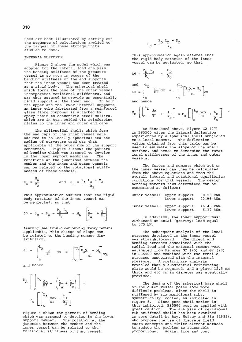
The ellipsoidal shells which form the end caps of the inner vessel were assumed to be locally spherical and the radius of curvature used was that applicable at the outer rim of the support concerned. Figure 3 shows the pattern of bending which was assumed to develop in the upper support membrane. The, rotations at the junctions between the member and the inner and outer vessels can be related to the rotational stiffnesses of these vessels.
and 6 r = P A L A ' M A
L^ D D
This approximation again assumes that the rigid body rotation of the inner vessel can be neglected, so that
A 8 =
and
A6 =
P D L D
EI dx EI dx
and hence
dx EI
1_ k - P_ D xdx L
o *c
As discussed above, Figure G2 (27) in BS5500 gives the lateral deflection experienced by a spherical shell subjected to a local moment. The deflection values obtained from this table can be used to estimate the slope of the shell surface, and hence to determine the rotational stiffnesses of the inner and outer vessels.
The forces and moments which act on the inner vessel can then be calculated from the above equations and from the overall lateral and rotational equilibrium conditions for that vessel. The design bending moments thus determined can be summarised as follows:
This approximation assumes that the rigid body rotation of the inner vessel can be neglected, so that
A6 = A A
Assuming that first-order bending theory remains applicable, this change of slope can be related to the bending moment distribution .
m EI dx =
L A ^ P AX - M A
EI d*
and hence
dx EI
'L
EI k B
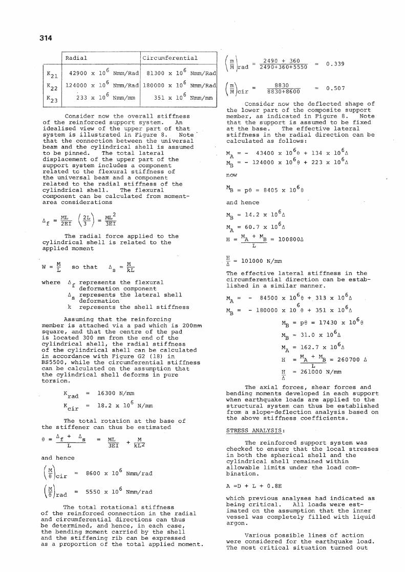
Figure 4 shows the pattern of bending which was assumed to develop in the lower support member. The rotation at the junction between the member and the inner vessel can be related to the rotational stiffness of that vessel.
Outer vessel: Upper support Lower support
Inner vessel: Upper support Lower support
8.53 kNm 20.9 6 kNm
16.4 5 kNm 6.17 kNm
In addition, the lower support must withstand an axial (gravity) load equal to 375 kN.
The subsequent analysis of the local stresses developed in the inner vessel was straightforward. The direct and bending stresses associated with the radial load and the external moment were estimated from Figures G2 (25) and G2 (28) in BS5500 and combined with the tensile stresses associated with the internal pressure. A preliminary analysis revealed that a substantial reinforcing plate would be required, and a plate 12.5 mm thick and 450 mm in diameter was eventually provided.
The design of the spherical base shell of the outer vessel posed some more difficult problems, since the shell is stiffened by six meridional ribs, symmetrically located, as indicated in Figure 5. Since pure shell action is thus inhibited, BS5500 must be applied with great caution. The analysis of meridional rib stiffened shells has been examined in some detail by Roy, Hulsey and Zia (1981) , who propose the use of discrete field macro concepts and finite element methods to reduce the problem to reasonable proportions. Again, time and cost
311 TABLE 2 : Displacement Ductility Levels
DESCRIPTION OF STRUCTURAL TYPE V
All structural types which are designed to remain elastic under the design earthquake loading 1
Concrete or steel tanks on the ground 2
Vessels supported on a ductile pedestal or skirt or where hold-down bolts are designed for tension yield under the design earthquake loading 3
Structures designed for foundation rocking 2
TABLE 3 : Scaling Factors for Earthquake Return Periods
TABLE 4 : Design Seismic Coefficients
Earthquake
Return Period (years)
Scaling Factor
75 0.83
150 1.00
500 1.30
1000 1.50
y
l 0.78
2 0.45
3 0.35
Figure 4: Bending in Lower Internal Support
312
limitations prevented the application of such relatively sophisticated methods.
The primary aim of the analysis was to provide a reasonably accurate, somewhat conservative, alternative to a full finite element approach and, in the event, two quite different methods were used in parallel.
1. The calculations submitted to the approving authority were based on elementary structural principles, and followed as closely as possible the pattern suggested in BS5500.
2. These calculations were checked using a standard micro-computer package for space frame analysis which had been developed by the author and which makes provision for curved members.
BASIC CALCULATIONS:
The principal assumption on which these calculations were based was that the ribs and the shell were separate systems, and that forces and moments were distributed between them in proportion to the corresponding lateral and rotational stiffnesses. One consequence is that no local stress analysis was carried out for the bending moment and vertical force at the base of the inner support, since beam action could be assumed to be completely dominant in that region. The total vertical shear force was instead assumed to be distributed equally between the six beams, while the bending moment associated with lateral earthquake loads was distributed in proportion to the effective stiffness of each beam in the plane of the lateral load. The resultant beam stresses proved to be well within the allowable limits.
EXTERNAL SUPPORTS:
In order to determine the manner in which the forces and moments transmitted through the external supports are shared between the stiffening ribs and the shell, the effective lateral and rotational rib stiffness must be established. Consider the meridional rib sketched in elevation and in section in Figure 6.
Note that the width of the shell surface which can be expected to contribute to the beam stiffness of the rib is controlled by the shell geometry near the centre of the system and by the shear lag and local buckling characteristics elsewhere. The manner in which the effective shell width should be determined in such circumstances has been considered in some detail by Moffatt and Dowling (19 75) and by Evans and Taherian (1977), and reference was made to the design rules suggested by these authors.
The lateral and rotational rib stiffnesses adjacent to the external supports were then determined by numerical integration of the appropriate virtual work equations
| - 18600 N/mm and ~ = 360 x 1 0 6 Nmm/rad
The corresponding lateral and rotational stiffness values for the spherical shell were estimated from Figure G2 (23) and Figure G2 (27) in BS5500.
j = 91000 N/mm and ™ = 2500 x 10° Nmm/rad
The lateral loads and moments transferred through the external supports were assumed to be shared between the shell and the rib in proportion to the above stiffnesses. However, a preliminary analysis revealed that the calculated local stresses in the shell would exceed the allowable limits, and that some reinforcement would be needed.
SUPPORT REINFORCEMENT DETAILS:
The existing support members were reinforced by a 310UB46 welded via connecting plates to the fabricated channel which comprised the existing support member and to the cylindrical portion of the outer shell, as shown in Figure 7. The connecting plates were made 200 mm square and 12 mm thick for convenience in welding and to ensure adequate clearance. The universal beam was not primarily intended to add directly to the flexural stiffness of the existing support member, but rather to increase the total rotational stiffness at the junction between the support and the outer vessel. In practice, this involved transferring some portion of the applied forces and moments from the spherical end shell to the main cylindrical shell.
Since the addition of the reinforcing member meant that a substantial base plate would be required in any case, the decision was taken to design for complete base fixity. The slope deflection equations for the composite support member thus took the form.
M A = K l l 6 A + K 1 2 6 B + K 1 3 A
M B = K 2 1 °A + K 2 2 0 B + K 2 3 A
where represents the bending moment at the lower end represents the bending moment at the upper end
0 A represents the rotation at the lower end 0 B represents the rotation at the upper end A represents the relative lateral
deflection
The stiffness coefficients were again determined by numerical integration of the appropriate virtual work equations, and are summarised below:
Radial Circumferential
K l l 56400 x 1 0 6 Nmm/Rad 148000 x 1 0 6 Nmm/Rad
K 1 2 43400 x 1 0 6 Nmm/Rad 84500 x 1 0 6 Nmm/Rad K 1 3 134 x 1 0 6 Nmm/mm 313 x 10^ Nmm/mm
Cont'd.
A A
ELEVATION SECTION A-A
314
Radial Circumferential
K 2 1 42900 X 1 0 6 Nmm/Rad 81300 x 1 0 6 Nmm/Rad
K 2 2 124000 x 10 6 Nmm/Rad 180000 x 10 6 Nmm/Rad
K 2 3 233 x 10 6 Nmm/mm 351 x 1 0 6 Nmm/mm
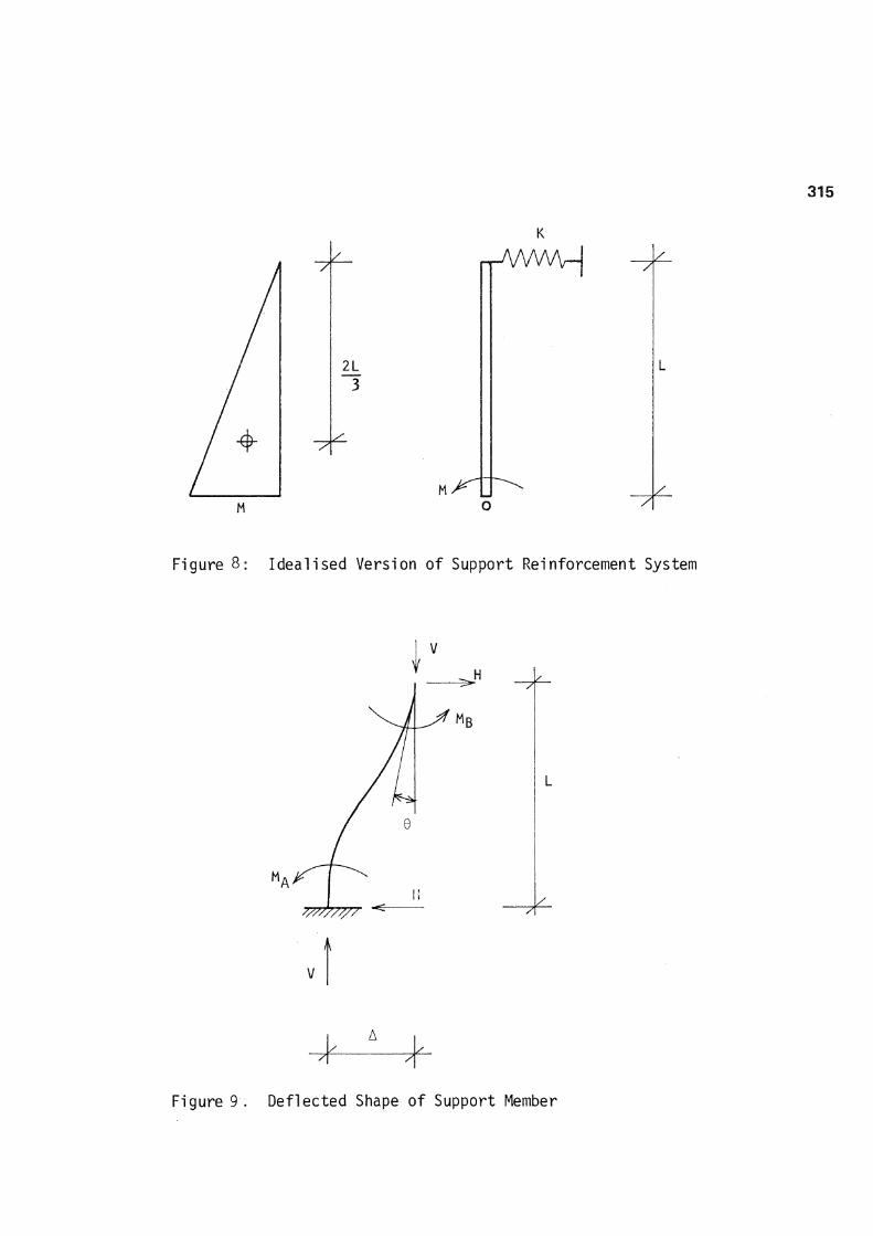
Consider now the overall stiffness of the reinforced support system. An idealised view of the upper part of that system is illustrated in Figure 8. Note that the connection between the universal beam and the cylindrical shell is assumed to be pinned. The total lateral displacement of the upper part of the support system includes a component related to the flexural stiffness of the universal beam and a component related to the radial stiffness of the cylindrical shell. The flexural component can be calculated from moment-area considerations
m M irad
M cir
2490 + 360 2490+360+5550
8830 8830+8600
= 0.339
0 .507
Consider now the deflected shape of the lower part of the composite support member, as indicated in Figure 8. Note that the support is assumed to be fixed at the base. The effective lateral stiffness in the radial direction can be calculated as follows:
43400 x 10 66 + 134 x 10 6A 124000 x 10 + 223 x 10 UA
= p6 = 8405 x 10 6(
and hence
ML 2EI
The radial force applied to the cylindrical shell is related to the applied moment
W = M . A M L S ° t h a t A s = kL
where A^ represents the flexural deformation component
A represents the lateral shell s deformation
k represents the shell stiffness
Assuming that the reinforcing member is attached via a pad which is 200mm square, and that the centre of the pad is located 300 mm from the end of the cylindrical shell, the radial stiffness of the cylindrical shell can be calculated in accordance with Figure G2 (18) in BS5500, while the circumferential stiffness can be calculated on the assumption that the cylindrical shell deforms in pure torsion.
K = 16300 N/mm rad ' K . = 18.2 x 1 0 6 N/mm cir 7
The total rotation at the base of the stiffener can thus be estimated
= f
and hence
\6 jcir
= ML 3EI
8600 x 10 Nmm/rad
M ,6 Irad = 5550 x 10 Nmm/rad
The total rotational stiffness of the reinforced connection in the radial and circumferential directions can thus be determined, and hence, in each case, the bending moment carried by the shell and the stiffening rib can be expressed as a proportion of the total applied moment.
= 14.2 x 10 UA
M A = 60.7 x 10 6A M + M H = LLA B = 100800A
101000 N/mm H A The effective lateral stiffness in the circumferential direction can be established in a similar manner.
+ 313 x 10 A
+ 351 x
31.0 x 10"
10 6A - 84500 x 10
- 180000 x 10
Mg = p6 = 17430 x 10 €
M B
M A =
H =
H = A
162.7 x 10 A M A + lAB = 260700 A
L 261000 N/mm
The axial forces, shear forces and bending moments developed in each support when earthquake loads are applied to the structural system can thus be established from a slope-deflection analysis based on the above stiffness coefficients.
STRESS ANALYSIS:
The reinforced support system was checked to ensure that the local stresses in both the spherical shell and the cylindrical shell remained within allowable limits under the load combination.
A =D + L + 0.8E
which previous analyses had indicated as being critical. All loads were estimated on the assumption that the inner vessel was completely filled with liquid argon.
Various possible lines of action were considered for the earthquake load. The most critical situation turned out
315
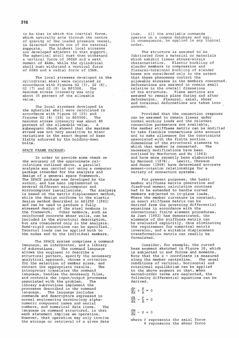
Figure 8: Idealised Version of Support Reinforcement System
A
V
11 1 /
Figure 9. Deflected Shape of Support Member
K
316
to be that in which the inertial force, which naturally acts through the centre of gravity of the loaded pressure vessel, is directed towards one of the external supports. The highest local stresses are developed adjacent to that support. The spherical shell must then withstand a vertical force of 300kN and a nett moment of 4kNm, while the cylindrical shell must withstand a vertical force of 60kN and a radial force of 15kN.
The local stresses developed in the cylindrical shell were calculated in accordance with Figures G2 (5) , G2 (6) , G2 (7) and G2 (8) in BS5500. The maximum stress intensity was only about 35 percent of the allowable value.
The local stresses developed in the spherical shell were calculated in accordance with Figure G2 (25) and Figures G2 (8) (28) in BS5500. The maximum stress intensity was about 80 percent of the allowable value. A subsequent check showed that the maximum stress was not very sensitive to minor variations in the exact degree of base fixity achieved by the holding-down bolts.
SPACE FRAME PACKAGE:
In order to provide some check on the accuracy of the approximate calculations outlined above, a parallel analysis was carried out using a computer package intended for the analysis and design of a general space framework. The SPACE package was developed by the author, and has been implemented on several different minicomputer and microcomputer installations. The analysis is based on the matrix displacement method, while the design conforms to the elastic design method described in AS1250 (1981) and can be used to produce a fully stressed design of the steel members in the framework. Other members, such as reinforced concrete shear walls, can be included in the structural description, but are considered only in the analysis. Semi-rigid connections can be specified. , External loads can be applied both to the nodes and to the individual members.
The SPACE system comprises a command language, an interpreter, and a library of subroutines. The command language allows the engineer to describe a structural pattern, specify the necessary analytical approach, choose a criterion for the selection of member sizes, and extract the appropriate results. The interpreter translates the command language, handles the necessary files, and controls the input/output processes associated with the problem. The library subroutines implement the processes described in the command language. The language includes commands and descriptors expressed in normal engineering terminology.alphanumeric component names and serial numbers, and numerical data items. The language is command structured, in that each statement implies an operation. However, that operation may only involve the storage or retrieval of a given data
item. All the available commands operate on a common database and may, in consequence, be applied in any logical order.
The structure is assumed to be fabricated from a material or materials which exhibit linear stress-strain characteristics. Elastic buckling of slender members in compression and flexural-torsional buckling of slender beams are considered only to the extent that these phenomena control the allowable stresses in the members concerned. Deformations are assumed to remain small relative to the overall dimensions of the structure. Plane sections are assumed to remain plane during and after deformation. Flexural, axial, shear and torsional deformations are taken into account.
Provided that the connection response can be assumed to remain linear under normal working loads and the relevant connection parameters are available, the member stiffness matrix can be modified to take flexible connections into account and to make allowance for the constraints associated with the finite section dimensions of the structural elements to which that member is connected. The necessary modifications have been outlined by Monforton and Wu (1963) and have more recently been elaborated by Macleod (1976). Lewitt, Chesson and Munse (1969) have determined accurate moment-rotation relationships for a variety of connection systems.
For present purposes, the basic member stiffness matrix generation and fixed-end moment calculation routines had to be extended to handle curved members subjected to in-plane loads. Where the member curvature is constant, an exact stiffness matrix can be derived from the governing differential equations in accordance with the conventional finite element procedures. As Just (1982) has demonstrated, the elements of the stiffness matrix can be evaluated explicitly, thus eliminating the requirement for numerical matrix inversion, and a suitable displacement transformation matrix can readily be formulated.
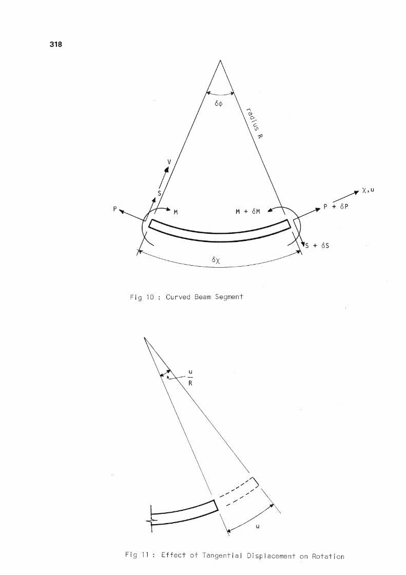
Consider, for example, the curved beam segment sketched in Figure 10, which is subjected to end forces and moments. Note that the x - coordinate is measured along the member centreline. The usual conditions of vertical, horizontal and rotational equilibrium can be applied to the above segment so that, when second-order terms are neglected, the following differential equations can be derived.
f- + I = o dx R lis - E = o dx R
where P represents the axial force S represents the shear force
317
M represents the bending moment R represents the radius of curvature
These equations can be formulated more conveniently in terms of the angle sub.tended by the member segment at the centre of curvature
d<j> dx R
and hence
H + s = o dcf> ds P = 0
so that by elimination
0 -̂/"^V S
E represents the modulus of elasticity
A represents the cross-sectional area
I represents the second moment of area
The resulting differential equations can be solved to give the axial and radial displacement functions in terms of six independent coefficients which correspond to the in-plane deflection and rotation components at each end of the member segment. Note in particular that the total member rotation at any point is a function of both the axial and the radial displacements. As indicated in Figure 11, the axial displacement increases the total rotation, so that
1 R
dy d$ + u
from which the shear force variation can be established
S = A coscf) + B sincj)
where A and B are constants to be determined from the boundary conditions. The variation in the bending moment can be established in a similar manner from the final equilibrium equation.
M =C + D cos<j> + E sin<j>
Consider now the relationship which exists between the end forces and displacements, defined in accordance with the conventions indicated in Figure 10. The axial force will tend to cause an increase in the member length, but the axial strain associated with the variation in the axial deflection will be reduced when a radial deflection exists, to give the nett value
du - [Rd<J> - (R-v) d<J>]
Rd(f>
and hence du d<J)
In a similar manner, the bending moment will tend to cause an increase in curvature. The increase in curvature associated with the variation in the radial deflection along the member centreline must be further supplemented by the increase associated with the overall radial deflection, to give the nett value
R 2 dcj> \d<J> dv 1
R-v
and hence, when second order terms are neglected
EI d__ dcf>
dy + v
where u represents the axial deformation v represents the radial deformation
The fixed-end forces and moments associated with any in-plane loading pattern can be determined by equating the work done by these forces and moments to the work done by the member loads as the member moves through the displacement functions calculated in the above manner.
Simple trans formation matrices can be devised to relate the end load and displacement components thus determined to the overall coordinate system for the structure in question, and hence to evaluate the member stiffness matrix, load vector and displacement vector.
EQUIVALENT FRAME ANALYSIS:
The principal aim of this analysis was not so much to determine the local stresses in the immediate vicinity of the supports. These stresses decay rapidly as one moves away from the support. The aim was rather to validate the overall distribution of forces and moments assumed in the approximate calculations outlined above. Several analyses were carried out using different frame configurations for both the shell and the support systems. Considerable care was taken to model the torsional characteristics of both the radial and the circumferential members, with particular reference being made to the recommendations of Taherian and Evans (1977).
In the event, the results obtained did generally support the assumed force and moment distribution although there was some indication that, in the immediate vicinity of the external supports, the approximate analysis significantly underestimated the stiffening effect of the supporting members.
CONCLUSIONS:
The modifications described above could be regarded as being successful in the sense that they enabled the cryogenic pressure vessels to meet the requirements imposed by the Marine Division of the Ministry of Transport without any major variations in the original structural concept. Whether the modifications were really necessary or even desirable is quite another matter.
318
X."
Fig 10 : Curved Beam Segment
Fig 11 : Effect of Tangential Displacement on Rotation
319
Direct comparisons between the alternative method applied to an elastic structure and the strength method applied to a ductile structure are rather difficult. The critical problem in the design of the above pressure vessels turned out to be the local stresses developed near the internal and external supports. These stresses amount to bending stresses in thin shells with fairly large radii of curvature. The local bending moments at the external supports are relatively small and, for comparative purposes, the local stresses there might be assumed to be controlled by the axial forces in the supporting members. In the most critical situation the axial force associated with gravity loads is equal to 12 5kN while the force associated with the specified earthquake loads is about 32 5kN (making some allowance for local bending moments).
Consider first the design criteria imposed by the alternative method. Assuming that the allowable bending stress is based on 60 percent of the yield stress, an optimal design would satisfy the equation
3 (0.60) F = 125 + 0.8(325)
F = r 6 4 °
where F represents the required material yield strength
3 represents a geometrical constant
In fact, the analysis of the unmodified system indicated that the maximum local stress intensity was about 40 percent higher than the allowable level.
Consider now the design criteria imposed by the strength method, and suppose that ductility was to be provided by hoId-down bolts designed for tension yielding. Assuming a 25 percent over-strength allowance, and a design lateral force equal to 58 percent of that applicable to elastic design, the basic design equation takes the form
3.F = 1.25 (125 + 0.58(325))
= 390
Had a ductile design approach, which is apparently regarded as satisfactory for industrial plant of vital national importance, been applied, the pressure vessels themselves would have required no modification. Indeed, from a purely pragmatic point of view, it seems quite reasonable that a pressure vessel which has not been specifically designed for earthquake loads, but which has in all other respects been well conceived and executed, should become acceptable when provided with a carefully designed ductile support system.
In this particular case, the modifications required to ensure that the vessels complied with elastic design criteria led to substantial delays in the delivery of urgently needed pressure vessels and the expenditure of valuable overseas funds. It is to be hoped that either
the recommendations for the seismic design of petrochemical plants, which appear to be logical in format and to set reasonable performance levels, or a suitably extended version of NZS 420 3, will in future be accepted for a much wider range of industrial plant and equipment.
BIBLIOGRAPHY:
ASME
BSI
CANE, F.J.
EDMONDS, F.D. GILLIES, A.G. NORTON, J.A.
EVANS, H.R. and TAHERIAN, A.R.
EVISON, R.D. and MOWAT, A.F.
HULSEY, J.L. ROY, D.K. ZIA, P.
LEWITT, C.W. CHESSON, E. MUNSE, W.H.
MOFFATT, K.R. and DOWLING P.J.
MONFORTON, G and WU, T.S.
SAA
"Boiler and Pressure Vessel Code Section VIII Div I" American Society of Mechanical Engineers, 1980.
"BS5500: Unfired Fusion Welded Pressure Vessels" British Standards Institution, 1982.
"The Effects of Earthquake Loads on the Design of Pressure Vessel Shells" Conference on Engineering Design for Earthquake Environment, Inst. Mech. Eng., Nov. 1978.
"Recommendations for the Seismic Design of Petrochemical Plants" IPENZ Conference, Christchurch, Feb. 19 82.
"The Prediction of the Shear Lag Effect in Box Girders" Proc ICE, Vol 63, Part 2, Mar. 1977.
"The Seismic Design of Industrial Plants" Trans IPENZ, Vol 9, No. 3/CE, Dec. 1982.
"Restraint Characteristics of Flexible Riveted and Bolted Beam-to-Column Connections", University of Illinois, Engineering Experiment Station, Bulletin 500, 1969.
"Shear Lag in Steel Box Girder Bridges" Structural Engineer, Vol 53, No. 10, Oct 1975.
,R."Matrix Analysis of Semi-Rigidly Connected Frames", Proc ASCE, J. Struct. Div., Vol 89, ST6, 1963.
"AS1250: Steel Structures Code", Standards Association of Australia, 1981.
TAHERIAN, A.R. and EVANS, H.R.
"The Bar Simulation Method for the Calculation of Shear Lag in Multi-Cell and Continuous Box Girders" Proc ICE, Vol 63, Part 2, Dec 1977.
BSI "PD6439: A Review of the Methods of Calculating Stresses due to Local Loads and Local Attachments of Pressure Vessels" British Standards Institution, 1969.