Seismic Design and Construction of Precast Concrete Buildings in New Zealand Robert Park Professor Emeritus Department of Civil Engineering University of Canterbun/ Christchurch, New Zealand Trends and developments in the use of precast reinforced concrete in New Zealand for floors, moment resisting frames and strucfural walls of buildings are described. Currently, almost all floors, most moment resisting frames and many one- to three-story structural walls in buildings are constructed incorporating precast concrete elements. Aspects of design and construction, particularly the means of forming connections between precast concrete elements, are discussed. The paper emphasizes seismic design since that is where fhe major difficulties exist in using precast concrete in New Zealand. Confidence in the use of precast concrete in an active seismic zone has required the use of an appropriate design philosophy and the development of satisfactory methods for connecting the precast elements together. ince the early 1960s in New Zealand, there has been a S steady increase in the use of precast concrete for smictural compo- nents in buildings. The use of precaqt concrete in flooring systems has be- come commonplace since the 1960s. leaving cast-in-place floor construc- tion generally uncommon. Also, pre- cast concrete non-structural cladding for buildings has been widely used. During the boom years of building construction in New Zealand, in the mid- to late 1980s. there was also a significant increase in the use of pre- cast concrete in moment resisting frames and structural walls. This came about because the incorporation of precast concrete elements has the ad- vantages of high qudlity control, a re- duction in site formwork and site labor. and increased speed of construc- tion. In particular. with high interest rates and demand for new building space in New Zealand in the mid 1980s. the advantage of speed gave precast concrete a distinct edge in cost. Contractors readily adapted to pre-
Transcript
Seismic Design and Construction of Precast Concrete Buildings in New Zealand
Robert Park Professor Emeritus Department of Civil Engineering University of Canterbun/ Christchurch, New Zealand
Trends and developments in the use of precast reinforced concrete in New Zealand for floors, moment resisting frames and strucfural walls of buildings are described. Currently, almost all floors, most moment resisting frames and many one- to three-story structural walls i n buildings are constructed incorporating precast concrete elements. Aspects of design and construction, particularly the means of forming connections between precast concrete elements, are discussed. The paper emphasizes seismic design since that is where fhe major difficulties exist in using precast concrete in New Zealand. Confidence in the use of precast concrete in an active seismic zone has required the use of an appropriate design philosophy and the development of satisfactory methods for connecting the precast elements together.
ince the early 1960s in New Zealand, there has been a S steady increase in the use of
precast concrete for smictural compo- nents in buildings. The use of precaqt concrete in flooring systems has be- come commonplace since the 1960s. leaving cast-in-place floor construc- tion generally uncommon. Also, pre- cast concrete non-structural cladding for buildings has been widely used.
During the boom years of building construction in New Zealand, in the mid- to late 1980s. there was also a
significant increase in the use of pre- cast concrete i n moment resisting frames and structural walls. This came about because the incorporation of precast concrete elements has the ad- vantages of high qudlity control, a re- duction in site formwork and site labor. and increased speed of construc- tion. In particular. with high interest rates and demand for new building space i n N e w Zealand i n the mid 1980s. the advantage of speed gave precast concrete a distinct edge in cost.
Fig I Exdiriple$ rit daniLige to pre<ast concrete buildings caused by malor earthquakes
cast concrete and the new constnictioii techniques resulting from on and off- site Sahrication of building coniponents. Also. the ovailahility of tall. high ca- pacity crimes and other equipment have iiinde precast erection more efficient.
New &&land i s in u zone o f high to moderate earthquake activity and the use of preciist concrete in seismic re- gions requires specid provisions for design 2nd coIisiructiim I t i s of inter- est that moment resisting frames and structural walls incorporating precast concrete elements have been ohserved in some countries to peri’orm poorly in earthquakes.
The ohserved Pailtires have been mainly due to brittle (non-diictile) be- hw io r o f poor connection details be- tween the precast concrete elements. poor detailing of components and poor design concepts (see Fig. I). As a re- su l t , the use oí’ precast concrete in frames and walls was shunned in New Zealand Sor many years.
Confidence in the use O S precast concrete in moment resisting frames and structural walls in the 1980s in New Zealand required the develop- ment o f satisfactory methods for con- necting the precast elements together. The then current New Zealand con- crete design standard, NZS 3101:19X2.’ like concrete design sian- dards of niany countries, contained coniprehensive provisions f«r the seis- niic design of cast-in-place concrete structures but did iiot have seismic provisions covering all iispects of pre- cast concrete structures. Hence. the in-
crease in the use of precast concrete in the 1970s required a good deal of in- novation.
The design methods introduced for the connections between precast ele- ments o f moment resisting frames gen- erally aimed to achieve behavior as for a monolithic concrete structure (cast- in-place emulation). The design meth- ods for structural walls aimed at be- hav ior as for either a monol i th ic siructure or a jointed structm with re- atively weak joints between elements.
A Study Group of the New Zedand Concrete Society, the New Zealand National Society for Earthquake Engi- neering and the Centre for Advanced Engineering of the University of Can- terhury was formed in 1988 to sum- marize and present data on precast concrete design and construction, to identify special concerns, to indicate recommended practices. and to recom- mend topics requiring further research. The outcome o f the deliberations of the Study Group was the publication o f a manual entitled “Guidelines for the Use of Structural Precast Concrete in Buildings,” which was first printed in August 1991.
A second edition incorporating re- search undertaken in the first half of the 1990s was published in December 1<)99.2 A revision o f the New Zealand concrete design standard was pub- lished in 199%’ This revision contains additional provisions for the seismic design of structures containing precast concrete based on that research.
This paper describes aspects of the
design and construction o f buildings in New Zealand incorporating precast concrete structural elements in floors, moment resisting frames and struc- tural walls. i t emphasizes design and construction for seismic resistance, since that i s where the greatest diffi- culties exist in the connection o f pre- cast elements.
SEISMIC DESIGN CONCEPTS FOR PRECAST CONCRETE
IN BUILDINGS
General Requirements For moment resisting frames and
structural wails incorporating precast concrete elements, the challenge i s to find economical and practical means of connecting the precast elements to- gether to ensure adequate stiffness, strength, ductility and stability. The designer should consider the loadings during the various stages of construc- tion and at the serviceability and ulti- mate limit states during the liFe of the structure.
In common with other countries, the seismic design forces recommended for structures in the current New Zealand standard for general structural design and design loadings for build- ings, NZS 4203:1YY2,4 are signifi- cantly less than the inertia forces in- duced if the structure responded in the elastic range to a major earthquake.
The design seismic force i s related to the achievable structure ductility factor
Plastic hinge X Shear iailure (a) Frame with (b) Column (c) Mixed sidesway
graviy and sidesway mechanism with seismic loading mechanism plastic hinges and
shear failures
Fig. 2. Undesirable modes of behavior for tall seismically loaded moment resisting frames in the post-elastic range.
p = A,-IA,, where A,- is defined as the maximum horizontal displacement that can be imposed MI the structure during several cycles of seismic load- ing without significant loss in strength, and 4 is defined as the horizontal dis- placement at fust yield assuming elas- tic behavior of the cracked structure.
According to the New Zealand load- ings standard? structures may be de- signed as W e or structures of lim- ited ductiiity or elastically responding.
For ductik structures, p = 5 or 6 is used to determine the appropriate spectra of seismic coefficients and the design horizontal seismic forces at the ultimate limit state typically vary between 0.038 and 0.20g. de- pending on the seismic zone, the soil category, the importance of the structure and the fundamental pe- riod of vibration of the structure. For structures of limited ductility, p = 2 or 3 is used and the design hori-
zontal seismic force at the ultimate limit state typically varies between 0.038 and 0.398. For elastically responding struc- tures, p = 1.25 is used. Note that the design seismic forces
for cast-in-place concrete structures and for structures incorporating pre- cast concrete elements of the same available ducrility recommended in the New Zealand loadings code‘ are identical.
Capacity Design Before about the mid-l970s, it was
customary in the seismic design of structures to use linear elastic struc- tural analysis to determine the bending moments, axial forces and shear forces due to the design gravity loading and seismic forces, and to design the members to be at least strong enough to resist those actions.
N (a) Wall actions (b) Diagonal (c) Sliding (d) Hinge
tension shear sliding shear
As a result. when the structure as designed and constructed was sub- jected to a severe &quake, the man- ner of post-elastic behavior was a mat- ter of chance.
Flexural yielding of structural mem- hers could m u r at any of the regions of maximum bending moment, and shear failures could also occur, de- pending on where the flexural and shear strengths of members and joints were fust reached. Hence, the behav- ior of such structures in the pst-elas- tic range was somewhat unpredictable.
For example, for monolithic mo- ment resisting frames, overstrength of the beams in flexure or understrength of the columns in flexure could result in column sidesway mechanisms (see Fig. Zh) (soft story behavior). Also. the flexural overstrength of members leads to increased shear forces when plastic hinges form, which could result in shear failures (see Fig. 2c). These undesirable failure modes could cause catastrophic collapse of the frame.
In the case of monolithic cantilever structural wails, there are a range of possible undesuahle modes of behav- ior. Overstrength of the wall in flexure could cause failure modes in either di- agonal tension shear, sliding or hinge sliding (see Figs. 3b. 3c and 3d) which have limited ductility.
There is no doubt that the confi- dence of New Zealand designers that adequate ductility may be achieved in structures, either totally cast-in-place or incorporating precast concrete ele- ments, has come about mainly as a re- sult of the introduction of the capacity design approach. The capacity design approach is the result of research and development in New Zealand.
The method was developed by dis- cussion groups of the New Zealand National Society for Earthquake Engi- neering in the 1970s and by Park and Paday.’ The capacity design approach was first recommended by the New Zealand loadings standard in 1976 and by the New Zealand concrete design standard in 1982.’ The capacity design approach is described in more detail by Park? Paulay and Priestley,’ and Park, Paulay and Bull!
To ensure that the most suitable mechanism of post-elastic deformation does occur in a structure during a se-
PCI JOURNAL
vere earthquake. New Zealand design ~ e d n d a r d s ~ , ~ require that ductile Struc- tures be the subject ofcupucity design. In the capacity design of ductile struc- tures. the steps are:
I . First, appropriate regions of the primary lateral earthquake force resist- ing structural system are chosen and suitably designed and detailed for ade- quate dPsign strength and ductility during a severe earthquake.
2. Next, all other regions of the structural system. and other possible failure modes, are then provided with sufficient nominal srrmgth to ensure that the chosen means for achieving ductility can be maintained throughout the post-elastic deformations that may occur when the flexural oversfrengrh develops at the plmtic hinges.
T h e use o f capaci ty des ign has given designers confidence that struc- tures can he designed for predictable ductile behavior during major eartb- quakes. In purticular, brittle elements can be protected. Yielding can be re- stricted to ductile elements as intended by the designer.
The steps of the capacity design a p proach according to the New ZRRland concrete design standard,' a described above, require consideration of three levels of member strength, namely, de- sign strength $AS", nominal strength S, and overstrength S,, as defined below.
Design strengfh, @Yn, is the nominal strength S, multiplied by the appropri- ate strength reduction factor 4 s 1.0, where 4 is to allow for smaller mdte- rial strengths than assumed in design and variations in workmanship, di- mensions of members and reinforce- ment positions. Note that in European standards, material factors y? and yc are used to reduce the characteristic steel and concrete strengths, respectively. instead of 4 factors.
Nomind srrength S. is the theoreti- cal strength calculated using the lower characteristic Strengths ( 5 percentile values) of the steel reinforcement and concrete and the member cross sec- tions as designed.
Oversrrrngth S,, is the maximum likely theoretical strength calculated using the maximum likely overstrength of the steel reinforcement and of the concrete including the effect of con- finement. and reinforcement area in-
cluding any additional reinforcement placed for construction and otherwise unaccounted for in calculations.
Recommended Mechanisms of Post-Elastic Behavior for Monolithic Moment Resisting Frames
For moment resisting f rames of buildings, the best means of achieving ductile post-elastic deformations is by flexural yielding at selected plastic hinge positions, since with proper de- sign and detailing the plastic hinges can be made adequately ductile.'"
Significant post-elastic deforma- tions due to shear o r bond mecha- nisms are to be avoided since with cyclic loading they lead t o severe degradation of strength and stiffness and to reduced energy dissipation due to pinched load-displacement hystere-
sis loops. Post-elastic deformations due to flexural yielding at well de- signed plastic hinge regions result in stable load-displacement hysteresis loops without significant degradation of strength, stiffness and energy dissi- pation.
The preferred mechanism for pre- cast concrete equivalent monolithic moment resisting frames is a beam sidesway mechanism (see Fig. 4a). A beam sidesway mechanism occurs as a result of strong column-weak beam design.' The ductility demand at the plastic hinges in the beams and at the column hases is moderate for this mechanism and can easily be provided in design. A column sidesway mecha- nism is not permitted (except for the exceptions given below), since it can make very large demands on the duc- tility at the plastic h inges in the columns of the critical story.' Column
I (a) Weak Coupling (b) stronger Coupling of Walls of Walls
sidesway mechanisms (soft stories) have often led to the collapse of build- ings during earthquakes.
To ensure that failure in flexure can- not Dccur in parts of the structure not designed for ductility, or that failure in shear cannot occur anywhere in the svUctllre. the maximum actions likely to be imposed on the structure should be calculated from the probable flexn- ral overstrengths at the plastic hinges laking into account the possible factors that may cause an increase in the flexu- ral sú'engtb of the plastic hinge regions.
These factors include an actual yield strength of the longitudinal reinforc- ing steel, which is higher than the lower characteristic yield strength
used in design and additional longitu- dinal steel strength due to strain hard- ening at large ductility factors ( the sum of these two factors is referred to as the steel overstrength). The tlexural overstrength in New Zedland is taken as 1.25Mn. where M. is the nominal flexural slrength.
To avoid column sidesway mecha- nisms, the design column bending mo- ments need to he amplified (strong column-weak beam design) t o take into account beam flexural ove r - strength. higher mode effects and con- cumnt earthquake loading.'-'
The New Zealand concrete design standard' recommends that the column bending moments at the center of
Cast.ln-place ooncrete -,
:. 7. iype of support of precast concrete hollow-core íloor units by precast concrete beams used in New Zealand.'
beam-column joints derived by elastic structural analysis for the equivalent static design seismic forces acting in a principal direction of the frame be multiplied by an amplification factor of at least I .9 f«r one-way frames or at least 2.2 fur two-way frames. The am- plified column bending moments so determined are to be resisted by the nominal flexurul s t rength of t h e columns in uniaxial bending. These amplification factors take into account the possible flexural overstrength of the beams, the effects of higher modes of vibration of the frame and the effect of seismic loading acting along both principal axes of the frame simiiltane- ously in the case of two-way frames.
The New Zealand concrete design standard' has only two exceptions to the requirement of the strong column- weak beam design approach:
I . For ductile fvames of one- or two- story buildings (see Fig. 4b). or in the top story of multistory buildings. c o - umn sidesway inechanisms are permit- ted (that is, plastic hinges occurring si- multaneously at the top and bottom of all the columns of a story). In such cases. the design seismic forces are those associated with a structure duc- tility factor p = 6 since the curvature ductility demand at the plaitic hinges in the columns in such cases of low frames is not high as can be provided by proper detailing.
2. In some buildings in areas of low seismicity andlor where beams have long spans, the gravity load considera- tions may govern and make a strong column-weak beam design impractica- ble. In such cases, ductile frames three stories or higher may be designed to develop plastic hinges in any story si- multaneously at the top and bottom ends of some columns. while plastic hinges develop in beams at or near the other columns in that story which re- main in the elastic range. The columns that remain i n the elastic range will prevent a soft story failure (see the mixed sidesway mechanisms in Fig. 4c). Such frames are required to be de- signed for the design seismic force as- sociated with p equal 10 12 times the ratio of the total shear capacity of the columns remaining in the elastic range to the total story shear to he devel- oped. hut not more than p = h.
I t shuuld be appreciated that the mechanisms of Fig. 4 are idealized in that they involve possible post-elastic behavior obtained from slatic ''push- «ver" analysis with the frame sub- jected to code type equivalent static seismic forces. The actual dynamic situation may be different, due mainly to the effects of higher modes of v i- bration of the structure.
For example, the curvature ductility demand at the plastic hinges in the beans in the Iuwer region ofthe frame may be greater than in the upper re- gion. However, considerations such as those shown in Fig. 4 can be regarded as providing the designer with a rea- sonable feel for the situation. Nonlin- ear dynamic analyses indicate that mechanisms such as those shown in Fig. 4 do form
Recommended Mechanisms of Post-Elastic Behavior for Structural Walls
íhct i le capacity of structural walls i s required to be ubtained by plastic hinge rotation as u result of flexural yielding, with a displacement (struc- tural) ductility factor p of 6 or less, de- pending o n thc height-tu-length ratio «f the wall, and in the case of coupled walls also depending on the ratio of the overturning nioment resisted by the coupling walls to that resisted by the wall b a e d
The preferred mechanism for a monolithic cantilever structural wall in- volves a plastic hinge a l the base. Fig. S shows desirable mechanisms of post- elastic deformation of monolithic struc- tural walls during severe seismic load- ing with coupling beams between them. If the cuupling is wcak (for exam-
ple, only from fluor slabs), the walls will act as individual cantilever walls connected by pin-ended links (see Fig. Sa). I f the coupling beams are stiffer and have significani flexural strength, but not sufficient t« cause shear failure of the walls. plastic hinging will also develop in the coupling beams (see Fig. Sb).
h inted precast concrete wall con- struction (with relatively weak joints between the precast elements) could develop other mechanisms of post- elastic deformation and need to be de-
'12 Or SeMcsabiiiiy deRecilon and crack conlml
1.2m wideprecast hdlow-mm h r
Support baam forming part of lwo way duciüe
(r "Papdip' seismic tie reinforcemenl, hw per momanl resisting
1.2m wide slab. irame slructura
(a) Far Type 1 Support'
Continuily miniomemen1 R10 bars as
Exrenl of cast-in-place
conmie (b) For Type 2 Support
Fig..l0. Arrangements oí
precast reinforced concrete members and cast-in-place
concrete for constructing
reinforced concrete moment resisting
frames.’, ’*l6
cas14n-place concra1e Cas1-m place concrale and top sleel in beam \ Midspan
Precast or
Midspan
(a) System 1 . P-.< Beam Unlt. Eelween Columns (bj Synam 2 -Precast Beam Unlla Through Columns
(e) System 3 - Pncssi FiJnH6
Noles 0 Precast Cancram [ Casi-in.place concrele
Reinlorcemnt in precmt con~rele not shown
signed as structures of limited ductility or to respond in the elastic range.
Recommended Mechanisms of Post-Elastic Behavior for Mondithic Dual Systems For dual system (combined moment
resisting frames and smcturai wails), the deformations of the frames will be controlled and limited by the much stiffer walls. Fig. tía shows the mecha- nism pfe.xred for frames, that is, weak heam-strong column behavior with plastic hinging occurring in the beams and at the bases of the columns and walls. However, strong heam-weak column behavior may be admitted in every story of the frame (see Fig. 6h) because a wall proportioned using ca- pacity design principles will remain elastic above the plastic hinge at the base and its stiffness will prevent a “soft story” failure from developing in the h e . Without a wall. such a frame system designed for ductile response will normally have to be restricted to buildings of one or two stories.‘
Detailing for Ductility Structures need to be detailed so as
to passess sufficient ductility to match
the ductility required by the seismic forces used in design.
The most important design consid- eration for detailing plastic hinge re- gions of reinforced concrete members for ductility is the provision of appm- priate quantities of transverse rein- forcement in the form of rectangular stirrups, or hoops with or without cross ties, or spirals. The transverse reinforcement needs to be adequate to act as shear reinforcement, to confine and hence to enhance the ductility of the compressed concrete, and to pre- vent premature huckiing of the com- pressed longitudinal reinforcement.’
Joint core regions of heam-to-col- umn connections also need special at- tention because of the critical shear and bond stresses that can develop there during seismic loading.’
PRECAST CONCRETE IN FLOORS
Types of Floor Currently, the majority of floors of
buildings in New Zealand are con- structed of precast concrete units, spanning one way between hedm or walls. The precast concrete units are
either of pretensioned prestressed or reinforced concrete (solid slabs. voided slabs, rib slabs, single tees or double tees), and generally act com- positely with a cast-in-place concrete topping slab of at least 50 mm (2 in.) thickness and containing at least the minimum reinforcement required for slabs.
A~temdtiVeIy. precast concrete ribs spaced apart with permanent form- work of timber or thin precast con- crete slabs spanning between are used acting compositely with a cast-in- place concrete slab. Probably. the most common floors are constructed from precast concrete hollow-core floor units typically 200 mm (8 in.) deep, or deeper.
As well as carrying gravity loading, floors need to transfer the in-plane im- posed wind and seismic forces to the supporting structures through di- aphragm action. The best way to achieve diaphragm action when pre- cast concrete floor elements are used is to provide a cast-in-place reinforced concrete topping slab over the precast units.
Where precast concrete floor units are used without an effective cast-in- place concrete topping slab, in-plane
fbrce transfer due tu diaphragm action must rely on appropriately reinforced .joints hetween the precast units. This may he diff icult to achieve in some Iloors unless the connectiuns between the precast units i i re specifically de- signed and constructed.
Support Details
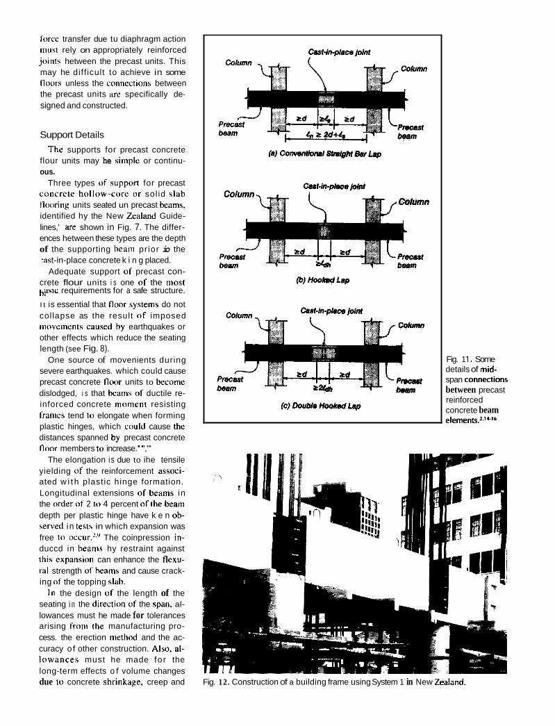
The supports for precast concrete flour units may he siniple or continu-
Three types ul' suppurl for precast cuncrete hollow-curc ur sol id slah tlo«niig units seated un precast beams, identified hy the New &?land Guide- lines,' me shown in Fig. 7. The differ- ences hetween these types are the depth of the supporting hrani pr ior io the
t-in-place concrete k i n g placed. Adequate support uf precast con-
crete flour units i s one of the most
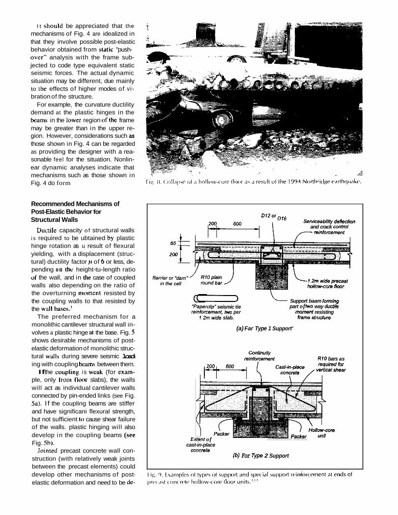
I t is essential that flour bystems do not collapse as the result « I imposed iiiuveinents caused by earthquakes or other effects which reduce the seating length (see Fig. 8).
One source of movenients during severe earthquakes. which could cause precast concrete fluor units to hecome dislodged, i s that hearns «I ductile re- inforced concrete munieiit resisting frames tend to elongate when forming plastic hinges, which could cause the distances spanned by precast concrete I lwr members to increase."',"'
The elongation i s due to ihe tensile yielding of the reinforcement assuci- ated w i t h plastic hinge formation. Longitudinal extensions 01' beams in the order uf 2 to 4 percent uf the heam depth per plastic hinge have k e n oh- scrved in tests in which expansion was free tu »ccur.25' The coinpression in- duccd in heams hy restraint against this expansiun can enhance the tlexu- rzil strength o f beams and cause crack- ing of the topping slah.
In the design of the length of the seating in the directiun o f the span. al- lowances must he made for tolerances arising froin the manufacturing pro- cess. the erection method and the ac- curacy o f other construction. Also. al- Iuwances must he made for the long-term effects o f volume changes due io concrete shrinkage. creep and
ous.
h. ASIL ' . requirements for a safe structure.
Fig. 1 1. Some details of mid- span connectims between precast reinforced concrete beam elements.'.' +lb
Fig. 12. Construction of a building frame using System 1 in New Zealand.
Eeam longltudinai relnforoement only shown
Fig 13. Hook%
Casl-in@ace @/¡?I cM>cIo
Top bars sNd imo place
, Nets. db - bar dlameter
2 U,, or L,,,,h~8~.g whichever Is less
g (hooks lo terminate al the lar slde o1 lhe joint core)
I lap oí bottom bars within inint core
&, = development lenglh 01 hooked anchoreges
for System 1 .d I
temperatures effecls, a well as for the effects of earthquakes.
Some concern has been expressed in New Zealand that there were cases i n construction where the support pro-
vided for precast flrmrs was inade- quate. In the IYXOs. the New Ixaland Code fnr design' had no specific re- quirements for the support «I precasi concrete flonrs.
As ii result. the ciin'ciii New %enlarid c ~ i i i c r c t e des ign \iaiicl;ird. NZS
concrete Iloiir o r r o i i l riienihcrs. wiih or without the presence of :I c;ist-iii- place cnncrete copping slah iiiidícir enti- t ini i i ty rei i i forcci i ic i i i . iioriiially e;icli nici i i her iiiid i IS \ u p p r t i ii- sy \ t e ni shall have h i g n di i i ic i isi i im selectcd so t1i:ii. iiiidcr ii rviisoniihlc cimhinii- tion o i unfiivimhlc consituctioii toler- iiiices, the disi;iiicc froin ihe eil;e of the siipptm t i i thc end o f the prec;isi irteiiihcr in ihc direciiim irt i t \ spiin i s at least I/,,,, 01' the clear spill1 hut i iot less than 50 iiiiii ( 2 iii.) iw si i l id or hol- Inw-et~re diihr (ir I 5 iiiiii ( 3 ii1.J f o r he;m, or rihheil iiieiiihers. iinwcwi-. i i shiiwii hy analysis or hy lest thiii the pertimiatice of ;iltcriiiitive suppori de- tails i s adeqiiatc. thc ;ib(ivc specified end distances need iioi he provided.
l h e iihiive rec,)i1iiiiciid:itioii. which requires proven alteriiiitivc siippwi de- tails unle\> the specified end dis1unccs are prrivicled. i s sii i i i l i ir iii the recniii- iiiciidaiiiiii iii ihe hiiililiiig codc o i ihc
3 1 0 1 : I Y O S . ~ p ~ i d e \ t11:1t ioi- ~ ~ C G I S I
Fig. 15. í ~ ~~
Eonrtruction oi the 152 m (499
American Concrete Institute, ACI 318-99."
One method of providing the alter- native details which permit smaller seating lengths is to use special rein- forcement between the ends of the pre- cast concrete floor units and the sup- porting beam, which can carry the vertical load in the event of the precast concrete floor units losing thcir seat- ing. The special reinforcemenr should be able to transfer the end reactions by shear friction across the vertical cracks at the ends of the units if the crack widths are relatively narrow or hy kinking of the reinforcement crossing the cracks if the crack widths are large.
This reinforcement can bc in the form of hanger or saddle bars. or hon- zontal or draped reinforcement. as rec- ommended by the New 2,ealand Guidelines? and recommended earlier by the Precast/Prestressed Concrete Institute and the Fédération Interna- tionale de la Pn5contrainte. For exam- ple, for precast concrete hollow-core
it) tall ANZ lower using System 2 in Aucklanci htatt A,.? ,uxI
units, the special reinforcement may be either placed in some of the cores which have been broken out at the top and filled with cast-in-place concrete or grouted into the gaps between the precast units.
Test.. conducted at the University of Canterbury"." on special reinforce- ment, placed in filled corn at the ends of hollowsore units and passing over precast supporting beams, have inves- tigated a number of types of special support reinforcement. They were found to be able to support al least the service gravity loads of the floor, in the event of loss of end seating.
The plain round straight or draped reinforcement with hooked ends shown in Fig. 9 are favored.* Plain round end hooked reinforcement was found to perform better than deformed reinforcement since bond failure prop- agating along the plain round ban al- lowed extensive yielding along the bar. therefore allowing substantial plastic elongation before fracture."
MOMENT RESISTING FRAMES INCORPORATING
PRECAST REINFORCED CONCRETE ELEMENTS
Moment resisting frames incorpordt- ing precast reinforced concrete ele- ments have become widely used in New Zealand. The design aim has been to achieve behavior of the frame as for monolithic cast-in-place construction (cast-in-place emulafion).'4-'5.'h
The general trcnd in New Zealand for niultistory buildings with moment resisting frame3 is to design the perimeter frames with sufficient stiff- ness and strength to resist most of the hwizontal seismic loading. The more flexible interior frames will be called o n to resist less of the horizontal forccs. the exact amount depending on the relative stiffnesses of the perimeter and interior frames. If the perimeter tianies are relatively stiff. the colunins i i f the interior frames w i l l carry mainly gravity loading. Also. the inte-
Fig. 16. Construction of the 13-story perimeter frame of Unisys House using two-story high cruciform-shaped precast units (System 3) in Wellington, New Zealand.
rior columns can be placed wi th greater spacing between columns.
For the perimeter frames, the depth of the beams may be large without af- fecting the clear height between floors inside the building and the columns can be at close centers. The use of one-way perimeter frames avoids the complexity of the design of beam-to- column joints of two-way moment re- sisting frames. References 17 to 22 give details of several buildings con- structed in New Zealand which incor- porate significant quantities of precast concrete in their frames and floors.
Arrangements of Precast Concrete Members and Cast-in-Place Concrete
The precast reinforced concrete frame elemenu are normally connected by reinforcement protruding into re- gions of cast-in-place reinforced con-
crete. Three arrangements of precast concrete members and cast-in-place concrete, forming ductile moment re- sisting multistory reinforced concrete frames, commonly used for stmng col- umn-weak beam designs i n New zealand, are shown in Fig. 10. Fig. I I shows some midspan connection details used with Systems 2 and 3 of Fig. 10.
The precast concrete beam elements of System 1 of Fig. 10 are placed be- tween the columns and the bottom longitudinal bars of the beams are an- chored by 90-degree hooks at the far face of the cast-in-place joint core (see Figs. 12 and 13). Figs. 14, 15 and 16 show structures under construction using Systems 2 and 3 of Fig. 10.
For System 2, the vertical column bars of the column below the joint protrude up through vertical ducts in the precast heam unit (see Fig. 141, where they are grouted, and pass into the column above. The white plastic
tubes over the bars i n Fig. 14 arc there to help pass the bars through the ve r t - cal ducts. The plastic tubes are then removed. Those vertical hars are con- nected to the bars in the column above by splices if the column is of cub in - place concrete or by steel sleeves or ducts which are groutcd if the column is of precast concrete (see Fig. 17).
The columiis of the precast elements of System 3 are coiinccted by longitu- dinal column bars which proirude intu steel sleeves or ducts in the adjiiceiit element and are grouted (see Figs. I6 and 17). The beams are connected using a cast-in-place joint at inidspan.
It should he noted that the capacity design procedure for these three sys- tems will ensure that yielding of the column bars at ihe connections is kept to a minimum. Fig. I 8 shows a further system using preiensioned prestressed concrete U-beams and cast-in-place reinforced concrete."
Many of the currently used connec- tion details shown in Figs. 10 to 18 have had experimental verifica- tion, 111.21.21 The vedication involved simulated seismic loading tests con- ducted on typical full-scale beam-to- column joint specimens. designed for strong column-weak beam behavior. to determine the performance of the hooked bar anchorage of the bottom bars of the beam in the cast-in-place concrete joint core in System 1 of Fig. 10, the performance of the grouted vertical column bars which pass through vertical ducts in the precast beam in System 2 of Fig. 10. and the performance of the composite beam shown in Fig. 18.
Simulated seismic loading tests have also been conducted to determine the performance of the cast-in-place midspan connections between precait beam elements shown in Fig. 1 I . The test results indicated performance as for totally cast-in-piace construction.
I
Precast Reinforced Concrete Moment Resisting Frames and Cast-in-Place Reinforced Concrete Structural Walls
Structures comprising both rein- forced concrete structural walls and flexible moment resisting frames can also be used to advantage. The struc- tural walls, normally of cast-in-place concrete, can be designed to resist ai- most ail of the horizontal forces acting on the building. The frames, being much more flexible than the walls, will be called on to resist only a small portion of the horizontal forces, the amount depending on the relative stiff- nesses of the walls and frames. The columns of such frames in the build- ing mainly carry the gravity loading.
When such systems are used in seis- mic regions, the frames can be de- signed for limited ductility, providing it can be shown that when the ductile walls have deformed in the postelas- tic range to the required displacement ductility factor or drift during severe seismic loading, the ductility demand on the frames is not large. A building so designed in New Zealand is shown in Fig. 19. The central cast-in-place reinforced concrete walls. forming the service core of the building, were de-
----Qroui and all
(a) Sled sleeve 25 mm rnlnlmum
Section A-A I Fig. 17. Steel sleeve splices and corrugated metal ducts used for column-to-coiurnn and slab-to-slab connections.
signed to resist the seismic loading. The perimeter frame of precast rein- forced concrete beams and the rein- forced concrete columns were de- signed mainly for gravity loading.
PRECAST CONCRETE STRUCTURAL WALLS
Construction Details
Most structural wails for multistory
in-place concttte, but significant use is made of precast concrete walls for smaller buildings (see Fig. 20). Precast reinforced concrete súucturai wall con- struction usually falls into two broad categories: “monolithic” or “jointed.”
in monolithic wall construction, the precast concrete elements are joined by “strong“ reinforced concrete con- nections which possess the stiffness, strength and ductiiity approaching that of cast-in-place concrete monolithic
buildings in New Zealand are of cast- construction.
Proprietary floor sptem and cast-in-place
topping
Pretensioned precast concrete U-beam
concrete beem
Fig. 18. A structural system involving precast pretension& prestressed concrete U-beams and castin-place reinforced ~oncrete.’~
173m H
(a) Typical tloor ~ i l an
Fig. 19. The Westpac Trust building constructed with a precast reinforced concrete perirnetcr Ir<iiiw with x i s r i i i c t o r< 1.5 r c 4 i d by cast-in-place reinforced concrete interior structural walls in Christchuri-h, Ncw %<.,il.iri<l.
(hi TIiv ~ i t ~ i n i t W r \lri i( tiirc'
Monolithic Wall Conslructioi i
Monolithic prccart rcinliirccd c<i i i - crete siriicturill wiill \ y t c i i i \ arc dc- signed ;iceording io ihc reqiiireiiiciilh for cart-in-place reiii lorccd coiicrctc c<IIlsINcli<ln. '
A l ihc hi ir i io i i td . jo i i i ts hmvee i i pre- casi c«ncreie wiill Ii:iiicIs (ir foiiiiil;i- lion hemis. ihc end5 of the patiel\ iirc
usually roiigliencd ((I :iv<iid sliding shear failure. ;tiid ihc .joint i \ iiiiidc
using niortar 01' grmil. The vcriicül re- iiiforceiiieiit protriidiiig Iroi i i oiic eiiii of the panel aiid cros\iiif t l ic .joiiii i\ connected 10 the ;id.i:iceiii p a w l o r liiund;itioii hcaiii hy iiir:iii~ <if :rmited \teel splice slccvcs o r grciiitcd corrii- g;11ed Illeli l l <liICiS <see Fig. 17 I.
PCI JOURNAL 7?
All horizonlal reinlorcement spliced wllh o(P standard
rizonlal rcement ‘(p stanc ¡.e. f
spliced lard
(a) Straight Lap Splices
Casr-implace All horizontal reiniorcemenl
reinforcement
panels roughened lloor level
(c) Hairpin Lap Splices
(b) Hooked Lap Splices
Casl-in-place 77 All hottzonral concrete or reinforcement
gmul iiried lomi harrpin spliced
precast 2 concrete of Sides p n t %ow or below wall
Vertic:il ioints between nrecast con- width to accommodate the Ian snlice number of ways - for exarnrrle. on a crete wall panels are typically strips o f cast-iii-place concrete into which hori- ziinval reiniorccnient from the ends of the adjacent panels protrude and are lapped. Fig. 21 shows some possihle vertical joint details hetween precast wall panels that make use of cast-in- place concrete. The widths o f the strips of cast-in-place concrete are de- termined by code requirements for lap lengths of horizontal reinforcement.
Fig. 21a shows ajoint with sufficient
. . length of the straight horizontal bars that protrude from the precast wal l panels. Fig. 2 I h shows hooked lap splices that enable the width of joint to be reduced. Figs. 21c and 21d show hairpin spliced bars, which may not be convenient to construct since once the lapping ban have been overlapped, the ability to lower the precast panels over starter bars is very restricted.
At exterior walls, support for pre- cast floor units can he achieved in a
steel angle anchored to the wall panel. on a concrete corbel, or on a recess in the wail panel. These connections are designed to transfer the floor inertia forces to the walls and to avoid loss of seating. Typical floor-to-wall connec- tion details are described elsewhere.?
jointed Wall Construction
I n jointed wa l l construction, the connection of precast reinforced con-
crete components is such that planes of significantly reduced stiffness and strength exist at the interface between adjacent precast concrete wall pe l s . Jointed construction has been exten- sively used in New zealand in tilt-up construction, generally of one- to three-story apartment, office and in- dushial buildings.
The buildings are normally designed as smnires of limited ductility or as elastically responding structures which require only nominal ductility. Gener- ally, tilt-up concrete walls are mured to the sdjacent structural elements using jointed connections comprising various combinations of concrete in- serts, bolted or welded steel plates or angle brackets, and lapped reinforce- m t splices within cast-in-place join-
The concreie inserts and bolted or welded steel plates need to be fixed to the concrete in a manner which en- sures ductile yielding of the reinforc- ing bars, bolts or plates before a brit- tle puiiout failure from the concrete occurs. This requires a capacity de- sign approach for the fixing to ensure that the desired yielding of the steel occurs under the most adverse
Tilt-up construction has been used to buüd smtures with complex geo- m&c and appealing architectural fea- tures. Some photographs of typical low-rise buildings constructed using precast concrete waiis are shown in Fig. 22.
Unfortunately, the current New Zealand concrete design code’ does not have design recommendations covering all aspects of tilt-up con- shUc(i0a. However, a research project has been in p m p s s at the University of C a n t e r b w ~ , ~ ~ ~ which has the aim of caralogfüng currently used connec- tion details, assessing and testing them whem necessary, and recommending appropriate details for tilt-up and jointed wmiruction.
ing ships.
strength conditions.
GENERAL Precast concrete is also commonly
used in New Zealand for a variety of industrial buildings, tanks and sports stadiums, including components such as stairways.
Successful precast concrete con- struction relies on a full understanding of the need for tolerances and the full implications of variations in dimen- sions. This understanding must be de- veloped by designers. fabricators and constructors.
The New Zealand requirements for toleianoes for prccait concrete construc- tion are given in the construction spec¡- ficatioa~ The New Zedand Guidelines’ suggests considering three different types of tolerances, namely, product, erection and interface tolerances.
THE FUTURE The building industry in New
Zealand has embraced the use of pre- cast concrete. All indications are that precast concrete construction will con- tinue to be used extensively in the fu- ture. The use of the capacity design approach and the development of ap- propriate methods for the detailing of connections and members have given designers the confidence that precast concrete can be used in an active seis- mic region such as New Zealand. The advantages of using precast concrete have given it a cost advantage.
CONCLUSIONS Based on accumulated design and
construction experience during the last three decades, the following conclu- sions can be made:
1. Coniidence in use of precast con- crete in structures in an active seismic zone such as New Zealand has re- quired the application of appropriate design approaches and the develop- ment of satisfactory methods for con- necting the precast elements together.
2. The advantages of using precast concrete have given it a cost advan- tage. Currently. almost all floors, most moment resisting frames and many one- to three-story walls in buildings in New Zealand are constructed incor- porating precast concrete. 3. A capacity design approach. de-
veloped i n New Zealand, is used to ensure that in the event of a major earthquake, yielding of the structure occurs only at chosen ductile regions. In particular, this means that for struc- tures incorporating precast concrete elements, ductility can be provided in regions away from potentially brittle connections.
4. Experimental and analytical re- search conducted during the last decade in New adland has led to seis- mic design provisions in the concrete design standard NZS 3101:1995 for the seating of precast concrete floor units and the design of the connections between precast elements in moment resisting frames. Guidelines have also been wrinen for aspects of the seismic design of tilt-up wall construction based on experimental and analytical research.
5. The fu ture of precast concrete construction in New Zealand appears to be bright.
ACKNOWLEDGMENT The author gratefully acknowledges
the helpful discussions he has had with members of the design and consttuc- tion profession in New Zealand, partic- ularly Mr. R. G . Wilkinson of the Holmes Group, Christchurch, Dr. A. J. O’Leary of Sinclair, Knight Mertz. Wellington, and Mr. G. Banks of Alan Reay Consultants, Christchurch. The author also gratefully acknowledges the financial support provided by the Earthquake Commission of New Zealand. Miss Catherine Price is thanked for her assistance in preparing this manuscript.
REFERENCES I. Cude r>f Prucrice , j i r rhe Design of Cuncrere Structures. Ni3
3 / O / : I Y R Z . Standards Assmiation of New Zealand. Welling ton. New Zealand. 1982. “Guidelines for the Use of Structural Precast Concrete in Buildings.” Report of a Study Group of the New Zealand Concrete Society and the New Zealand National Society for Earthquake Engineering, Centre for Advanced Engineering, University of Canterbury. New Zealand. First Edition. August 1991. 174 pp., and Second Edition. December 1999, 143 pp. The Design of Cuncrere Srrurrures, NZT 3i01:1995. Standards Asscxiation of New Zedland. Wellington, New Zealand 1995. Code of Pruirice fu r Generul Srrurrural Design and Design Loadings for Buildings, NZS 4203:/992. Standards Associa- tion of New Zealand. Wellington, New Zealand, 1992. Park, R.. and Paulay. T.. Reinforced Concrete Srrucrures, John Wiley and Sons, New York. NY. 1975.769 pp. Park, R., “Ductile Design Approach for Reinforced Concrete Frames,” Earrhyuuke Specrru. Professional Journal of the Earthquake Engineering Research Institute, V. 2, No. 3, May 1986, pp. 565-619. Paulay. T.. and Priestley. M. J. N.. Sei.rmic Design of Rein- fiirced Cuncrere and Masonry Buildings, John Wiley and Sons, New York. NY. 1992,744 pp. Park, R.. Paulay. T.. and Bull, D. K., “Seismic Design of Re- inforced Concrete S t ~ c t u r e ~ . ” Technical Report No. 20, New Zealand Concrete Society. October 1997. Fenwick, R. C.. and Davidson. B. J.. “Elongation in Ductile Seismic Resistant RC Frames,” Recen! Developments in oil- erul Force Trunsfer in Buildings, Special Publication SP157. American Concrete Institute. Fwnington Hills. Mi, 1995. pp. 143-170.
1 0 Restrepo, J. I.. Park. R.. and Buchanan, A. H., ’Tests on Con- nections of Earthquake Resisting Precast Reinforced Concrete Perimeter Frames of Buildings,” PCI JOURNAL, V. 40, No. 4. July-August 1995, pp. 44-61.
I I . ACI Committee 3 18, “Building Code Requirements for Struc- tural Concrete (ACI 318-99):‘ American Concrete Institute. Farmington Hills. MI. 1999.
12. Mejia. J. C.. and Park, R.. ”Tests on Special Reinforcement for the End Support of Hollow-Core Slabs.” PCI JOURNAL, V. 39. No. 5. September-October 1994. pp. 90-105.
13. Herlihy. M. D.. and Park. R., “Detailing Precast Flooring Sys- tems to Survive Loss of Support.” Proceedings of the Annual Technical Conference of the New Zealand Concrete Society, October 1996. pp. 130-139.
14. Park, R., “Seismic Design Considerations for Precast Concrete Construction in Seismic Zones.” Seminar on Precast Concrete Construction in Seismic Zones. V. I . Japan Society for the Pronilition of Science - United States National Science Foun- d a h h Tokyo, Japan, 1986, pp. 1-38.
IS. Park. R. , “Precast Concrete in Seismic Resisting Building
2.
3.
4.
5.
6.
7.
8.
Y.
Frames in New Zealand,” Concrete Inrernaiiunul. V. 12, No. 11. November 1990. pp. 43-51
16 Park, R.. “A Perspective on the Seismic Design of Precast Concrete Structures in New Zealand.” PCI JOURNAL, V. 40, No. 3. May-June 1995, pp. 40-60.
I 7. OLeary. A. J . , Monastra, D. P., and Mason, J. E., “A Precast Concrete Moment Resisting Framing System,“ Proceedings of the Pacific Concrete Conference, V. I , Auckland, New Zealand. November 1988. pp. 287-298.
18 Billings, I . J.. and Thorn. G . W., “NZI Centre-Design of Multi-Storey Towers,” Pmceedings of Pacific Concrete Con- ference, V. I , Auckland. New Zealand. November 1988, pp. 309-318.
19. Pwle, R. A., and Clendon. 1. E., “Mid City Towers - An Wi- cient Precast Concrete Framed Building.” Proceedings of the Pacific Concrete Conference. V. 1, Auckland. New Zealand, November 1988, pp. 319-332.
20. Silvester. D. B., and Dickson, A. R., “Fanshawe Street Build- ing - A Precast Concrete Study,” Prmedings of Pacific Con- crete Conference, V. 1, Auckland, New Zealand, November 1988. pp. 333-344.
21. OGrady. C. R.. “Precast Cruciform Columns, H-Frames and Precast Concrete Shear Wails in Building Construction,” Ro- ceedings of the Pacific Concrete Conference, V. l , Auckland, New Zealand, November 1988, pp. 345-354.
22. Raymond, W.. “Efficient Use of Structural Precast Concrete in High Rise Buildings - A Case Study,” Transactions of the instinition of Professional Engineers New Zealand, V. 19, No. IICE. November 1992. pp. 21-27.
23. Park. R.. and Bull, D. K., “Seismic Resistance of Frames tn- corporating Precast Prestressed Concrete Beam Shells.” PCI JOURNAL, V. 31, No. 4. July-August 1986. pp. 54-93.
24. Restrepo, J. I., Park, R., and Buchanan. A. H., “Design of Connections of Earthquake Resisting Precast Reinforced Gm- Crete Perimeter Frames of Buildings,” PCI JOURNAL, V. 40, No. 5. September-October 1995. pp. 68-77.
25. Restrepo. J. I.. and Park, R., “Review of Tilt-Up Consiniclian Details,” Proceedings of the Annual Technical Conference of New Zealand Concrete Society. Auckland, October 1993, pp. 3843.
26. Resmpo, J. I.. Cnsafulli. F., and Park, R., “Earthquake Resis- lance of Structures: The Design and Construction of Tilt-Up Reinforced Concrete Buildings.’’ Research Report 9 6 1 I , De- partment of Civil Engineering. University of Canterbury, Chrislchurch, New Zealand, September 1996.
27. Cnsafulli. F. I., Restrepo, I. I., and Park, R.. ”Seismic Design of Lightly Reinforced Precast Concrete Rectangular Wall Pan- els,” PCI JOURNAL, V. 47, No. 4, July-August 2002, pp. 304-121.
28. Concrete Consrrucrion Nzs 3/09:1997, Standards Association of New Zealand, Wellington, New Zealand. 1997.