Page 1 of 10 SEISMIC DESIGN CHALLENGES AND PRACTICAL SOLUTIONS FOR THE EVERGREEN LINE RAPID TRANSIT PROJECT Saqib Khan, M.A.Sc., S.E., P.E., P.Eng. Senior Project Engineer, MMM Group Limited, Canada [email protected]Jianping Jiang, Ph.D., P.Eng. VP and Partner, MMM Group Limited, Canada [email protected]Ali Azizian, Ph.D., P.Eng. Principal Specialist – Geotechnical/Seismic, Tetra Tech EBA, Canada [email protected]ABSTRACT: The new 11 km long Evergreen Line Rapid Transit Project links the cities of Coquitlam, Port Moody and Burnaby in the northeast sector of Metro Vancouver with a total estimated project value of $1.4B. It’s the first time that the performance-based seismic design criteria have been adopted for the design of the Vancouver SkyTrain system. A Seismic Peer Review Panel (SPRP) was established in accordance with the Project Agreement (PA) to review and approve the seismic design methodology for all structures along the new SkyTrain alignment. The Evergreen Line runs through enormously challenging ground conditions in Port Moody and Coquitlam highly susceptible to soil liquefaction under moderate to large magnitude of earthquakes causing variable, large-scale lateral spreading. For many challenging locations, non-linear structural analyses incorporating non-linear soil-pile-structure interaction and directional ground deformations were carried out to confirm structural performance. This paper presents a summary of the design criteria and performance requirements, the analytical challenges encountered while trying to analyze for large and mostly non-uniform lateral spreading, combining kinematic and inertial effects and the innovative design solutions for meeting the strict project performance criteria. A synopsis of three real design examples, each with a unique set of technical challenges, is provided. 1. Introduction The Vancouver Evergreen Line Rapid Transit Project is one of the first known rapid transit projects in Canada having utilized the multi-level, performance-based seismic design approach. The approximately 11 km long rapid transit line connects the City of Burnaby to the City of Port Moody and City of Coquitlam in the northeastern region of Metro Vancouver, British Columbia. The proposed Guideway structures consist of elevated, at-grade and tunnel sections. Referring to Figure 1 below, the project alignment comprises an upland area between Lougheed Town Centre Station and the north portal of the tunnel at Barnet Highway, and a low-lying area in Port Moody and Coquitlam Town Centre. The upland area is underlain by a thick sequence of dense to very dense glacial sediments overlying very dense glacial till-like materials, with a very low risk of liquefaction and lateral spreading for design seismic events. The areas east of the north portal of the tunnel to west of Pinetree Way and the section along Pinetree Way north of the Lougheed highway generally consist of loose to compact fill, debris fan, and shoreline deposits, over marine clay/silt deposits, over till-like materials. These areas are likely to experience significant liquefaction and large lateral spreading as a result (Golder Associates).
Transcript
Page 1 of 10
SEISMIC DESIGN CHALLENGES AND PRACTICAL SOLUTIONS FOR THE EVERGREEN LINE RAPID TRANSIT PROJECT
Saqib Khan, M.A.Sc., S.E., P.E., P.Eng. Senior Project Engineer, MMM Group Limited, Canada [email protected]
Jianping Jiang, Ph.D., P.Eng. VP and Partner, MMM Group Limited, Canada [email protected]
Ali Azizian, Ph.D., P.Eng. Principal Specialist – Geotechnical/Seismic, Tetra Tech EBA, Canada [email protected]
ABSTRACT: The new 11 km long Evergreen Line Rapid Transit Project links the cities of Coquitlam, Port Moody and Burnaby in the northeast sector of Metro Vancouver with a total estimated project value of $1.4B. It’s the first time that the performance-based seismic design criteria have been adopted for the design of the Vancouver SkyTrain system. A Seismic Peer Review Panel (SPRP) was established in accordance with the Project Agreement (PA) to review and approve the seismic design methodology for all structures along the new SkyTrain alignment. The Evergreen Line runs through enormously challenging ground conditions in Port Moody and Coquitlam highly susceptible to soil liquefaction under moderate to large magnitude of earthquakes causing variable, large-scale lateral spreading. For many challenging locations, non-linear structural analyses incorporating non-linear soil-pile-structure interaction and directional ground deformations were carried out to confirm structural performance. This paper presents a summary of the design criteria and performance requirements, the analytical challenges encountered while trying to analyze for large and mostly non-uniform lateral spreading, combining kinematic and inertial effects and the innovative design solutions for meeting the strict project performance criteria. A synopsis of three real design examples, each with a unique set of technical challenges, is provided.
1. Introduction
The Vancouver Evergreen Line Rapid Transit Project is one of the first known rapid transit projects in Canada having utilized the multi-level, performance-based seismic design approach. The approximately 11 km long rapid transit line connects the City of Burnaby to the City of Port Moody and City of Coquitlam in the northeastern region of Metro Vancouver, British Columbia. The proposed Guideway structures consist of elevated, at-grade and tunnel sections. Referring to Figure 1 below, the project alignment comprises an upland area between Lougheed Town Centre Station and the north portal of the tunnel at Barnet Highway, and a low-lying area in Port Moody and Coquitlam Town Centre.
The upland area is underlain by a thick sequence of dense to very dense glacial sediments overlying very dense glacial till-like materials, with a very low risk of liquefaction and lateral spreading for design seismic events. The areas east of the north portal of the tunnel to west of Pinetree Way and the section along Pinetree Way north of the Lougheed highway generally consist of loose to compact fill, debris fan, and shoreline deposits, over marine clay/silt deposits, over till-like materials. These areas are likely to experience significant liquefaction and large lateral spreading as a result (Golder Associates).
Page 2 of 10
The ground conditions were enormously challenging because of the resulting variable, large-scale lateral spreading. Ground improvement in the areas of deep liquefiable layers overlain by stiff crust near the ground surface were generally precluded due to proximity to the Canadian Pacific Railway, industrial facilities/buildings, underground utilities, or right-of-way constraints.
The Project Agreement (PA) specified a multi-level, performance-based seismic design criteria corresponding to different levels of seismicity, further described in the next section. A Seismic Peer Review Panel (SPRP) was established by the Owner (The Province of British Columbia) in accordance with the PA to review and approve the Seismic Design Strategy Memorandum (SDSM) for each structure along the new SkyTrain alignment. Design finalization and construction commencement could not take place without obtaining prior approval for the seismic design approach and methodology from the SPRP and certification on the seismic design checks by the Category III Independent Checker. Further details of the seismic peer review process are provided by Khan and Jiang (2015).
Fig. 1 - Evergreen Line Rapid Transit Project Alignment (reproduced with permission from the
Owner)
2. Performance Requirements and Design Criteria
2.1. Codes and Standards
The PA stipulated the following codes and standards for seismic analysis and design compliance in the order of precedence: • Evergreen Line Rapid Transit Project Agreement, Schedule 4, Part 2, Articles 4 [Structures], 5
[Seismic] and 6 [Geotechnical]. • BC Supplement to CAN/CSA-S6-06 • CAN/CSA-S6-06, Canadian Highway Bridge Design Code S6-06 • ATC-32 Improved Seismic Design Criteria for California Bridges: Provisional Recommendations • MCEER/ATC-49 Recommended LRFD Guidelines for the Seismic Design of Highway Bridges • AASHTO LRFD Bridge Design Specifications, 5
th Edition, 2012
2.2. Seismic Performance Levels
For the design of Guideway structures, the PA required either 3 or 4 Seismic Performance Level requirements to be met depending on the location along the alignment. Table 1 shows a summary of the Seismic Performance Levels and the corresponding Earthquake Events.
It should be noted that the 4 Level Performance Criteria are generally less onerous than the 3 Level Performance Criteria and are intended for the at-grade Guideway where the risk of structural failure is relatively lower. For all elevated Guideway portions, the 3 Level Performance Criteria is generally prescribed.
2.3. Earthquake Resisting Systems and Component Performance Requirements
The PA specified two types of Earthquake Resisting Systems (ERS): (a) Permitted ERS and (b) Potentially Permitted ERS. The Permitted ERS were limited to ductile substructure elements, such as columns, braced frames, and moment resisting frames along with base isolation and energy absorption devices. The design philosophy is to limit the inelastic response in the Permitted ERS to a specified range corresponding to each Seismic Performance Level. All other components were to be capacity-protected and remain essentially elastic. ATC 32 (ATC 32, 1996) was used for capacity-protected design.
The PA also stipulated that in case of minor inelastic response in piles, the Primary Contractor could propose the use of such piles as Potentially Permitted ERS subject to acceptance by the Owner based on the demonstration of compliant performance corresponding to each applicable Seismic Performance Level. Table 2 below provides a summary of the global and local performance requirements for the 3 Level Performance Criteria. Note that the steel rebar strain values are different from the ones originally specified in the PA; this change was approved by the SPRP and accepted by the Owner. Similarly, pile performance limits for piles under liquefaction scenario were proposed by the designer and agreed upon by the SPRP during the design.
Table 2: Global and Local Component Performance Requirements
Parameter Immediate Use Performance Level (1 in 100 Year Earthquake Event)
Repairable Performance Level (1 in 975 Year and Subduction Earthquake Events)
Column and Pile Strain/Rotation Limits:
Concrete
εc = 0.004
εcc : Mander confined
Page 4 of 10
Reinforcing Steel
Piles under Inertial Loading Concrete Piles under Liquefaction (Underside of Pile Cap) Steel Piles under Liquefaction (Underside of Pile Cap) In-ground Hinging of Piles Concrete Steel
εs = 0.025 Horizontal displacement corresponding to the Repairable Performance steel strain limit is to be no larger than 2/3 of the horizontal displacement capacity corresponding to the strain limits set out for the Life-Safety/No-collapse Performance level provided in the Project Agreement Capacity protected θp = 0.03 radians θp = 0.02 radians θp = 0.02 radians θp = 0.01 radians
Connections:
Column to Pier Cap Column to Pile Cap
Capacity protected Capacity protected
Capacity protected Capacity protected
Pier Caps and Straddle Bent Beams:
Capacity protected Capacity protected
Superstructure Components:
Capacity protected Capacity protected
Bearing Seat Widths:
Sized to meet Clause 4.4.10.5 of CSA S6-06; to be checked against maximum analytical movements
Sized to meet Clause 4.4.10.5 of CSA S6-06; to be checked against maximum analytical movements
Expansion Joints: Minimal damage is permitted as long as service can be maintained
Some repairable damage is permitted as long as it is localized and repairable
Page 5 of 10
3. Analysis and Design Challenges
3.1. Analysis
The design team faced several technical challenges while carrying out seismic analysis for this project. A brief summary of some critical issues is as follows:
• Given the variable soil properties, different p-y curves were developed and used for different pier locations. Response spectrum analysis therefore required several iterations for convergence to secant spring stiffness values compatible with ground displacements for each design event.
• The PA required consideration of both the kinematic and inertial loadings, but did not specify how to combine the two distinct loading effects. Research in this area indicates that individual peaks of the contributing dynamic and kinematic loading effects generally do not occur simultaneously. Recent research (Caltrans, 2012) recommends using a combination of 1.0 Kinematic loading ± 0.5 Inertial loading. This approach was approved by the SPRP. Two-node non-linear spring elements were employed for carrying out the kinematic analysis. The separate kinematic and inertial loadings were investigated using global 3D structural models. Lateral spread values were then applied to the foundations via the fixed side of the spring elements, thus imposing the ground deformation forces through the non-linear spring stiffnesses. After determining pile cap and column top displacements under kinematic loading alone using the global model, 50% of the inertial displacements were superimposed with 100% of the kinematic displacements in a local stand-alone model for each bent in order to obtain the combined loading effects. The combination could not be carried out in a global model and the key was to ensure that the force and displacement state at the end of kinematic loading was appropriately captured for each bent location before imposing the inertial deformation onto the bent.
• Both soil non-linearities (modelled using p-y curves) and material non-linearities (modelled using plastic hinges in columns and piles) required extensive computation times along with occasional numerical instabilities.
• Modelling of in-ground plastic hinges was an iterative process as the location of such a hinge is unknown at the outset.
3.2. Design
A summary of a few critical design challenges is as follows:
• The original PA specified very stringent rebar strain limits in the column plastic hinge zones. For example, the maximum allowable value for 35M bars for Repairable Performance Level was stipulated as 0.0086. No rebar yielding was allowed for the Immediate Use Performance Level. As design progressed for the various sections as part of the Seismic Design Strategy Memorandum (SDSM) approval process, it became apparent that the stipulated strain limits were too onerous and conservative. Structural design based on such low strain limits would not only result in unnecessary high rebar ratios leading to extreme congestion and construction difficulties but also create design difficulties for compliance with the Capacity Design principles. Recent research in the area of post-earthquake damage quantification (Priestly et. al. 1996; Priestly et.al. 2007) suggests that rebar strain limits in the range of 0.01 to 0.015 for Immediate Use could be considered reasonable. Through several rounds of discussions with the SPRP and the Owner, it was agreed to use more practical limits than those specified in the original PA. A Request for Variance was submitted and approved with new rebar strain limits of 0.005 and 0.025, respectively, for the Immediate Use and Repairable Performance Levels. As a further requirement, the designer was required to demonstrate that at the Repairable Performance Level, the structure has a 50% remaining capacity to Life-Safety/No-Collapse Performance Level in terms of global displacement.
• The project alignment runs through rapidly changing and enormously challenging soil conditions susceptible to liquefaction causing variable, large-scale lateral spreading. At several locations, where deep liquefiable layers and a stiff non-liquefiable crust near the surface were present, proximity to the Canadian Pacific Railway, industrial facilities/buildings, underground utilities, right-of-way constraints, etc. precluded ground improvements. Large piles founded in competent, non-liquefiable strata were
Page 6 of 10
considered an appropriate alternative solution at several locations. However, it was found that designing such piles to remain elastic under kinematic or a combination of kinematic and inertial loadings was not practical and would be extremely cost prohibitive. As per the PA procedures, Requests for Consent were submitted to the Owner for approving the use of large piles as Potentially Permitted ERS on a case-by-case basis, thereby allowing minor plasticity to occur in these components under the effects of kinematic or combined kinematic plus inertial loadings. Since the pile inelastic response limits were not explicitly defined by the PA, the in-ground plastic hinge rotation limits were proposed based on ATC 49 (MCEER/ATC 49, 1996) and accepted by the SPRP. Under inertial loading only, the piles were to be designed as capacity protected elements.
• Due to non-uniform lateral spreading, high variability in soil strength and stringent structural performance requirements, variable foundation and column strength and stiffness had to be employed in conjunction with suitable superstructure articulation to ensure design compliance. This proved to be a tedious and highly iterative process.
• The PA required that the design of the Fixed Facilities i.e. Stations be based on the “Post-Disaster” Importance Category, complying with the 2475-Year Return Period Earthquake Event per the British Columbia Building Code (BCBC, 2006). This introduced an inconsistency in the seismic design due to the fact that the Fixed Facility is designed for a different level of earthquakes and BCBC uses a force-based design approach. In discussions with the SPRP, it was agreed that the Guideway bents supporting the Fixed Facilities would be designed to comply with the performance-based requirements for the Guideway, while the Fixed Facility structures above or independent of the Guideway bents and their connections to the Guideway bents would be designed as per BCBC.
4. Design Examples
Large diameter concrete filled steel pipe piles passing through liquefiable layers and bearing on competent strata were found to be a robust structural solution for the Guideway foundations in highly liquefiable soils with no possibility of ground improvement. The pile diameters ranged from 762 mm to 1828 mm depending upon the severity of liquefaction. The designed piles were able to resist liquefaction induced loading including passive pressures on the pile caps due to crust effects with minor inelastic deformations. Three specific structures are discussed as follows summarizing the unique challenges faced and practical solutions obtained for each of the structures.
4.1. Reichhold Special Structure
The Reichhold Special Structure (RSS) comprises a simply supported span, and two continuously supported multi-span of three and five spans, respectively. The span between Abutment A2-1 and Pier P2-2 are simply supported; the spans between Piers P2-2 and Pier P2-5 form one continuous structure while spans between Pier P2-5 and Abutment A2-10 form the other. The guideway superstructure cross-section consists of four precast and prestressed concrete I-girders located underneath the running rails. The deck is composed of cast in place concrete topping over partial depth precast concrete panels supported on the girders. The substructure consists of a pier cap beam supported by a single 1525 mm diameter column centered under the guideway, except for Pier P2-9. All substructure pier columns are supported by piled foundations of steel pipe piles with a large pile cap, except for Pier P2-9 where steel pipe piles extend from the ground all the way to the pier cap.
The RSS is an example of a structure whereby the foundation soils change from very stiff and competent till-like material to very soft and highly liquefiable soils within a very short distance along the alignment. The west abutment (A2-1) of the Reichhold Structure is located in very stiff and competent till-like material with no liquefaction potential while the first pier (P2-2) at a 37.5 m distance away from the west abutment is founded in liquefiable soils with a predicted magnitude of lateral spreading equal to 60% of the lateral spreading predicted for the rest of the structure (Figure 2). This posed a significant challenge for the foundation design and required that variable pile sizes be used in order to mitigate uneven distribution of the loading effects among the Guideway bents. The effective design solution found after various iterations was to use smaller diameter (4-762 mm) piles at the first pier followed by large diameter piles (2-1828 mm) at the following 3 piers (P2-3 to P2-5). In addition, the superstructure at the first pier was made
Page 7 of 10
discontinuous by employing a pinned articulation for the first span and an expansion joint for the second span. The general design approach was to incorporate more flexibility into the structural system thus avoiding a “hard point” in the system and reducing concentration of extremely high local demands due to extreme liquefaction variability. A sensitivity analysis was also carried out for this structure by varying the lateral spread profile by +/-20%. Piers P2-6 to P2-9 also experience high liquefaction; however, the liquefaction in this zone is not variable and the less costly design solution comprising4-914 mm diameter piles was found to be adequate for these piers. The extended 4-914 mm pile bent was used in order to address the low clearance at Pier P2-9.
Fig. 2 – Reichhold Special Structure Lateral Spread Profile
4.2. Douglas Special Structure
The Lafarge Lake-Douglas Special Structure (DSS) is an 80 m long, 4-span continuous structure separated by expansion joints from the 3-span, 111.6 m long Douglas Crossover Structure to the south at Pier 1 and the 2-span 72 m long Douglas Tail Track Structure to the north at Pier 17 (Figure 3).
Fig. 3 – Douglas Special Structure Elevation
Page 8 of 10
The structure employs precast and prestressed concrete box girders to support the inbound and outbound track on either side of the central platform. Individual guideway beams approximately 19 m long are framed into Station’s straddle bents with expansion joints at the end piers, 1 and 17. The elevated station structure comprises the platform and steel moment-resisting frames supporting the roof structure. Straddle bent frames are used to support both the platform and the guideway beams. Each straddle bent is supported by columns founded on a combination of single large diameter caissons. The ground-based station structure is a one-storey reinforced concrete masonry wall building, supported on its own foundation comprising a suspended slab and 610 mm diameter piles for vertical loads.
A coupled FLAC analysis was carried out after determining the initial lateral spread profiles based on
simplified methods. Variable liquefaction (Figure 4) and the presence of a thick crust at this location
presented the risk of large differential movement between the Guideway and the Station Building leading
to pounding damage between the two structures. This made the initially proposed concept of
independently supporting the Station Building on its own foundations a non-starter from the seismic
design standpoint. An innovative design approach was required in order to structurally integrate the
Station Building foundations with the Guideway bents through the station. The final design concept was
centered on supporting the entire ground floor of the Station Building on a suspended concrete slab
further supported by large perimeter beams framed into the Guideway bent caisson foundations. As
capacity protected elements, fairly large perimeter beams had to be used, e.g. 1500 mm deep longitudinal
beams thickened to 2000 mm at the caisson connections and 1000 mm deep transverse beams (Figure
5). The suspended slab was designed with as a 450 mm thick element. To mitigate any potential risk of
large vertical displacement of the suspended slab under non-seismic loading, small diameter (610 mm)
steel pipe piles were installed along the building grid lines away from the perimeter beams. These piles
were founded with in the crust and it was assumed that these small piles will have no contribution to the
seismic resistance and the seismic load would be entirely transferred to the Guideway bent foundations.
Fig. 4 – Douglas Special Structure lateral Fig 5. Concrete grade beam and slab detail
spread profiles
4.3. CPR Special Structure
The CPR Special Structure comprises 15 spans made up of four continuous frames between Abutments A3-1 and A3-16 (Fig.6). Continuous frames include a three-span frame and three four-span frames. The guideway superstructure cross-section consists of four precast and prestressed concrete I-girders while the deck is composed of cast-in-place concrete topping over partial depth precast concrete panels supported on the girders. The substructure generally consists of a pier cap beam supported by a single column centered under the guideway, with the exception of Pier P3-6 where a straddle bent is required to
Page 9 of 10
cross the CPR mainline tracks. All substructure pier columns are supported by concrete-filled steel pipe piles with a large pile cap, except for piers P3-13 through P3-15, which consist of three concrete-filled steel pipe piles with reinforced concrete column extensions above grade, framing into a pier cap. All piers employing pile caps have 4 - 914 mm diameter pipe piles except at piers P3-2 and P3-6, where 2- 1800 mm diameter pipe piles have been used.
Fig.6 – CPR Special Structure Elevation
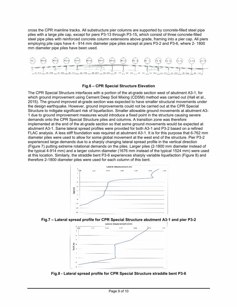
The CPR Special Structure interfaces with a portion of the at-grade section west of abutment A3-1, for which ground improvement using Cement Deep Soil Mixing (CDSM) method was carried out (Hall et al., 2015). The ground improved at-grade section was expected to have smaller structural movements under the design earthquake. However, ground improvements could not be carried out at the CPR Special Structure to mitigate significant risk of liquefaction. Smaller allowable ground movements at abutment A3-1 due to ground improvement measures would introduce a fixed point in the structure causing severe demands onto the CPR Special Structure piles and columns. A transition zone was therefore implemented at the end of the at-grade section so that some ground movements would be expected at abutment A3-1. Same lateral spread profiles were provided for both A3-1 and P3-2 based on a refined FLAC analysis. A less stiff foundation was required at abutment A3-1. It is for this purpose that 6-762 mm diameter piles were used to allow for some global movement at the west end of the structure. Pier P3-2 experienced large demands due to a sharply changing lateral spread profile in the vertical direction (Figure 7) putting extreme rotational demands on the piles. Larger piles (2-1800 mm diameter instead of the typical 4-914 mm) and a larger column diameter (1676 mm instead of the typical 1524 mm) were used at this location. Similarly, the straddle bent P3-6 experiences sharply variable liquefaction (Figure 8) and therefore 2-1800 diameter piles were used for each column of this bent.
Fig.7 – Lateral spread profile for CPR Special Structure abutment A3-1 and pier P3-2
Fig.8 - Lateral spread profile for CPR Special Structure straddle bent P3-6
Page 10 of 10
5. Conclusions
The Metro Vancouver Evergreen Line Rapid Transit Project is one of the first known rapid transit projects in Canada, which has utilized the multi-level performance-based seismic design criteria. Challenging ground conditions comprising significant and variable lateral spreading due to liquefaction and the aggressive design and construction schedule gave rise to several technical challenges. For many challenging locations, sophisticated non-linear structural analyses incorporating soil-pile-structurel interactions and directional ground deformations were carried out to confirm structural performance. Large diameter concrete filled steel pipe piles passing through liquefiable layers and bearing in competent strata were found to be a robust structural solution for the Guideway foundations in highly liquefiable soils with no possibility of ground improvement. At certain locations, foundation flexibility and variable pile sizes were introduced to avoid creating a fixed/hard point in the structural system. To this end, variable column sizes and reinforcement were also used to achieve favourable global behaviour. For the challenging Douglas Special Structure, the innovation design of structurally combining the Station Building foundation with the Guideway bents was able to meet desired performance. Superstructure articulation and continuity/discontinuity was advantageously incorporated to help with global structural behaviour. All design work has been completed and construction is currently underway. It is expected that the Evergreen Line will be in service by 2016.
6. References
AASHTO LRFD Bridge Design Specifications, 5
th Edition, 2012
ATC-32, “Improved Seismic Design Criteria for California Bridges: Provisional Recommendations”, 1996. BCBC, “British Columbia Building Code”, 2006. Caltrans, “Guidelines on Foundation Loading and Deformation Due to Liquefaction Induced Lateral Spreading”, 2012. Evergreen Line Rapid Transit Project Agreement, Schedule 4, Part 2, Articles 4 [Structures], 5 [Seismic] and 6 [Geotechnical], 2012. Golder Associates, “Technical Memorandum: Site-Specific Firm Ground (Class C) Response Spectra and Associated Acceleration Time Histories, Evergreen Line Rapid Transit Project, Greater Vancouver, BC”, December 2011. Hall, B.E., Azizian, A., Naesgaard, E., Amini, A., Baez, J.I., and Preece, M.L., “Evergreen Line Rapid Transit Project: Analysis and Design of Deep Soil Mix Panels to Mitigate Seismic Lateral Spreading. Deep Foundations Institute’s Deep Mixing Seminar, San Francisco, CA, June 2015. Khan, S.A., and Jiang, J., “Performance Based Seismic Design for the Vancouver Evergreen Line Rapid Transit Project – Process, Challenges and Innovative Design Solutions”, SEI/ASCE Structures Congress, April 23-25, 2015. MCEER/ATC-49, “Recommended LRFD Guidelines for the Seismic Design of Highway Bridges”, 2003. Priestly, M.J.N., Seible, F., and Calvi, G.M., “Seismic Design and Retrofit of Bridges”, 1996. Priestly, M.J.N., Calvi, G.M., and Kowalski, M.J., “Displacement-Based Seismic Design of Structures”, 2007.