45
Seismic Evaluation and Retrofit of Existing Steel Structures Canadian Seismic Research Network Robert Tremblay École Polytechnique, Montréal, Canada August 2013

Seismic Evaluation and Retrofit
of Existing Steel Structures
Canadian Seismic Research Network
Robert Tremblay
École Polytechnique, Montréal, Canada
August 2013

Plan
• Development of Guidelines based on
ASCE 41-13
• Braces & Connections in CBFs
• Connections in MRFs
• Use of Ductile Brace Fuses for CBFs
• Use of Supplemental Dampers

R. Tremblay, Ecole Polytechnique of Montreal 3
Guidelines Based on ASCE 41-13
Section Title
Ch 1 General Requirements
Ch 2 Seismic Performance Objectives
and Ground Motions
Ch 3 Evaluation and Rehabilitation Requirements
Ch 4 Tier 1 Evaluation
Ch 5 Tier 2 Deficiency-based Evaluation and Rehabilitation
Ch 6 Tier 3 Systematic Evaluation and Rehabilitation
Ch 7 Analysis Procedures and Acceptance Criteria
Ch 8 Foundations and Geologic Site Hazards
Ch 9 Steel
Ch 10 Concrete
Ch 11 Masonry
Ch 12 Wood And Light Metal Framing
Ch 13 Architectural, Mechanical, And Electrical Components
Ch 14 Seismic Isolation And Energy Dissipation
Ch 15 System Specific Performance Procedures
App 1 Tier 1 Checklists

Assessment of 10-Storey CBF in 1980
R. Tremblay, Ecole Polytechnique of Montreal 4
Y. Balazadeh-Minouei, S. Koboevic & R. Tremblay
Ecole Polytechnique
5 @ 9144 = 45 720
X-Bracing
X-Bracing
N-S
Chevron Bracing
Chevron Bracing
E-W
45
72
5 @
91
44
= 4
5 7
20
9 @
39
62
= 3
5 6
58
N
Gravity loads: Roof: Dead = 3.0 kPa Snow = var. Floor: Dead = 3.0 kPa Partitions = 1.0 kPa Live = 2.4 kPa Exterior walls = 1.0 kPa

Assessment based on NBCC 2010
& CSA S16-09 (Rd = 1.5)
R. Tremblay, Ecole Polytechnique of Montreal 5
X-Bracing
N-S
Braces

Assessment based on NBCC 2010
& CSA S16-09 (Rd = 1.5)
R. Tremblay, Ecole Polytechnique of Montreal 6
X-Bracing
N-S
Brace Connections

Assessment based on NBCC 2010
& CSA S16-09 (Rd = 1.5)
R. Tremblay, Ecole Polytechnique of Montreal 7
X-Bracing
N-S
Columns
R. Tremblay, Ecole Polytechnique of Montreal 8
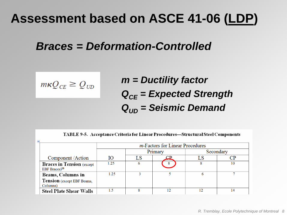
Assessment based on ASCE 41-06 (LDP)
m = Ductility factor
QCE = Expected Strength
QUD = Seismic Demand
Braces = Deformation-Controlled
R. Tremblay, Ecole Polytechnique of Montreal 9
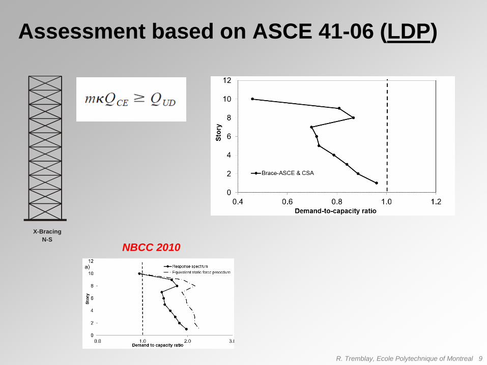
Assessment based on ASCE 41-06 (LDP)
X-Bracing
N-S
NBCC 2010

R. Tremblay, Ecole Polytechnique of Montreal 10
Assessment based on ASCE 41-06 (NDP)

R. Tremblay, Ecole Polytechnique of Montreal 11
Assessment based on ASCE 41-06 (NDP)
NBCC 2010
X-Bracing
N-S
ASCE 41 LDP

R. Tremblay, Ecole Polytechnique of Montreal 12
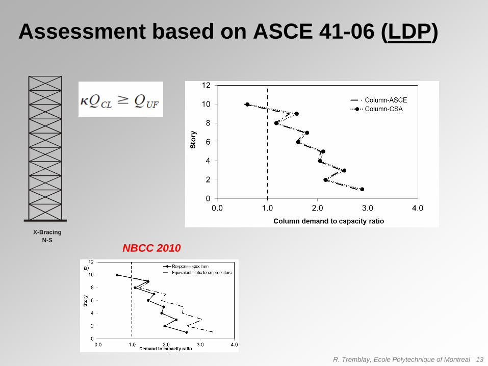
Assessment based on ASCE 41-06 (LDP)
QCL = Lower-Bound Strength
QUF = Seismic Demand
Columns = Force-Controlled
Columns subjected to P & M:
R. Tremblay, Ecole Polytechnique of Montreal 13
Assessment based on ASCE 41-06 (LDP)
X-Bracing
N-S
NBCC 2010

R. Tremblay, Ecole Polytechnique of Montreal 14
Assessment based on ASCE 41-06 (NDP)
X-Bracing
N-S

R. Tremblay, Ecole Polytechnique of Montreal 15
Assessment based on ASCE 41-06 (NDP)
NBCC 2010
X-Bracing
N-S
ASCE 41 LDP
R. Tremblay, Ecole Polytechnique of Montreal 16
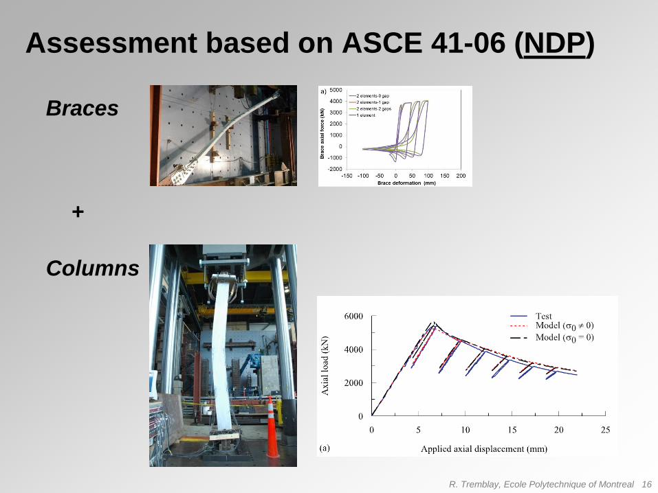
Assessment based on ASCE 41-06 (NDP)
Braces
Columns
+

R. Tremblay, Ecole Polytechnique of Montreal 17
Assessment based on ASCE 41-06 (NDP)
X-Bracing
N-S
ASCE 41 NDP
with linear columns

Assessment & Retrofit
4-Storey CBF (Braces & Connections)
R. Tremblay, Ecole Polytechnique of Montreal 18
Y. Jiang, R. Tremblay & L. Tirca
Ecole Polytechnique, Concordia University
4 @ 6 m = 24 m
6 @ 63
.5
= 381
558
44.5
290
44.544.5
50.8
[mm]
A325 3/4”Bolts
4 @
4 m
=
16
mW2
00
x3
6
W2
00
x3
6
W2
00
x5
2
W2
00
x5
2
734 kN
4 @
6 m
= 2
4 m
A
15
E
Structure Plan View
Frame Elevation
Brace Connection at Level 1
N
Gravity loads: Roof: Dead = 3.0 kPa Snow = 1.52 kPa Floor: Dead = 3.0 kPa Partitions = 1.0 kPa Live = 2.4 kPa Exterior walls = 1.0 kPa
2L102
x89x
9.5
2L102
x89x
7.9
2L76x
51x6
.4
785
kN
594
kN
306
kN
882 kN
2L127x76x9.5
W2
00
x5
2W
250
x8
0

R. Tremblay, Ecole Polytechnique of Montreal 19
In Braced Frame
In 12 MN Load Frame
Test Program on 2L Braces and Connections

R. Tremblay, Ecole Polytechnique of Montreal 20

R. Tremblay, Ecole Polytechnique of Montreal 21
Brace with End Gusset Plate ConnectionsFiber Cross-Section
End Connection ModelStitch
ConnectorEnd Connection
Detailed 2L Brace O/S Model

R. Tremblay, Ecole Polytechnique of Montreal 22

R. Tremblay, Ecole Polytechnique of Montreal 23

R. Tremblay, Ecole Polytechnique of Montreal 24
Retrofitted connection with
slotted holes
• 15% less capacity
• Similar ductility
Original Connection Retrofitted Connection
Retrofit Strategy

R. Tremblay, Ecole Polytechnique of Montreal 25
Hybrid Simulations (Collapse Predictions)
R. Tremblay, Ecole Polytechnique of Montreal 25
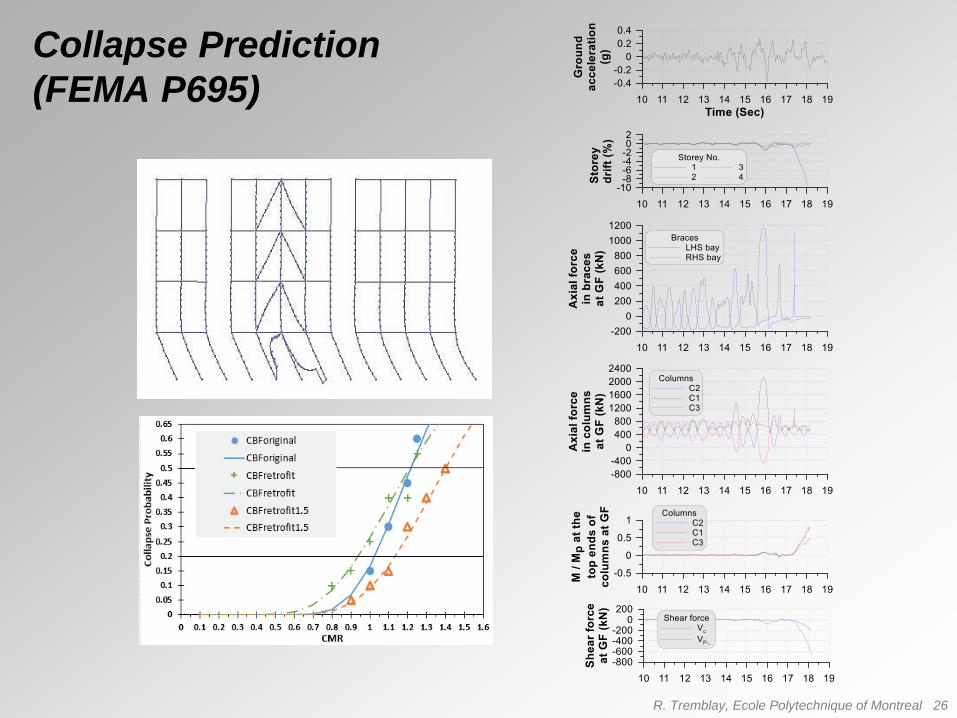
R. Tremblay, Ecole Polytechnique of Montreal 26
Collapse Prediction
(FEMA P695)

Brace Connections
R. Tremblay, Ecole Polytechnique of Montreal 27
P. Castonguay & R. Tremblay
Ecole Polytechnique
J. Hartley, A. Caruso & C. Rogers
McGill University
Samples made from new material Samples taken from existing
structures

R. Tremblay, Ecole Polytechnique of Montreal 28
0 40 80 120
inel (mm)
0
200
400
600
800
1000
P (
kN
)
D01X - Yielding on Brace Gross Section
D02X - Failure of Parallel Welds
D03X - Bearing and Tearing
D04X - Failure on Net Section
D05X - Bolt Shear Failure
D06X - Block-Shear Failure
0 10 20 30 40
inel (mm)
0
200
400
600
800
1000
P (
kN
)
a)
b)Strengthened:
Existing:

R. Tremblay, Ecole Polytechnique of Montreal 29
Assessment / Buildings per 1965 Codes

Connections in MRFs
R. Tremblay, Ecole Polytechnique of Montreal 30
N. Kyriakopoulos & C. Christopoulos
University of Toronto

R. Tremblay, Ecole Polytechnique of Montreal 31
Weld Zipping
Backing Bar
CJP
Weld
Failure

R. Tremblay, Ecole Polytechnique of Montreal 32
0 100 200 300 4000
100
200
300
400
500
600
Total Drift (mm)
Bas
e S
hea
r F
orc
e (kN
)
Frame Fm Pushover
2nd Floor
3rd Floor
4th Floor
Penthouse
Penthouse No P−D
N.A.Vb
Mb
Vb
P
Mc
P=Vb/ 2
Vc
Mc =M
b*(H/ 2-a)/ H
a
a
NOTE: Height of column = H
T = Cst + C
bearing
No force transfer in top plate
Cbearing
Cst
T
Cbearing
Vb
Cst
Vc

Use of Ductile Fuses
R. Tremblay, Ecole Polytechnique of Montreal 33
• Control Forces in CBFs
• Achieve Higher Displacement Capacities
• Develop Enhanced Hysteretic Response
to Control Drifts
-8 -4 0 4 8
/ y
-1.2
-0.8
-0.4
0.0
0.4
0.8
1.2
P / Py
HSS 102x76x6.4 - KL/r = 112
Tu
Cu

R. Tremblay, Ecole Polytechnique of Montreal 34
E. Desjardins, A. Desrochers & F. Légeron
Université de Sherbrooke

R. Tremblay, Ecole Polytechnique of Montreal 35
E. St-Onge & R. Tremblay
Ecole Polytechnique
R. Tremblay, Ecole Polytechnique of Montreal 36
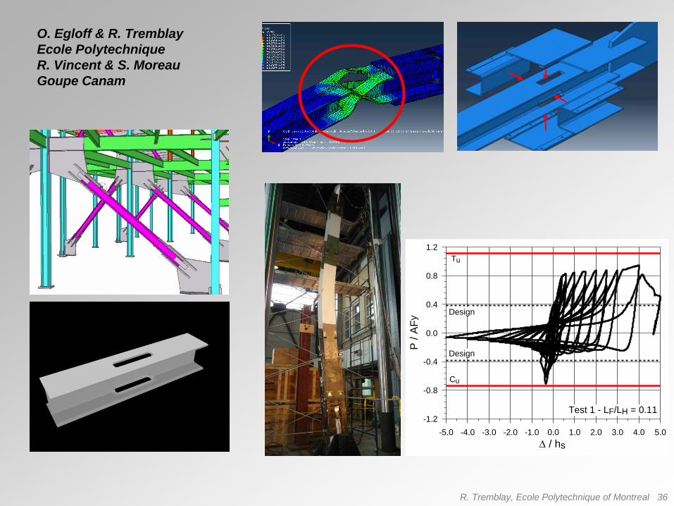
O. Egloff & R. Tremblay
Ecole Polytechnique
R. Vincent & S. Moreau
Goupe Canam
-5.0 -4.0 -3.0 -2.0 -1.0 0.0 1.0 2.0 3.0 4.0 5.0
/ hs
-1.2
-0.8
-0.4
0.0
0.4
0.8
1.2
P /
AF
y
Design
Design
Cu
Tu
Test 1 - LF/LH = 0.11

R. Tremblay, Ecole Polytechnique of Montreal 37
T. Morrison & C. Rogers
McGill University
0
20
40
60
80
100
120
140
0 10 20 30 40 50 60
Axi
al L
oad
(kN
)
System Deformation (mm)
Original vs. Retrofited Tests
Original Sample Retrofitted Sample
-800
-600
-400
-200
0
200
400
600
800
-200 -150 -100 -50 0 50 100 150 200
TestData1
TestData2
R6D09b1
R6D09b2

R. Tremblay, Ecole Polytechnique of Montreal 38
C. Caprarelli, N. Danila & L. Tirca
Concordia University
-80 -40 0 40 80Displace m ent [m m ]
-800
-400
0
400
800
Force [k N]
Ex pe rimenta l res ult
Pinchin g
Sk elet on curve

R. Tremblay, Ecole Polytechnique of Montreal 39
M. Gray, C. Christopoulos & J. Packer
University of Toronto
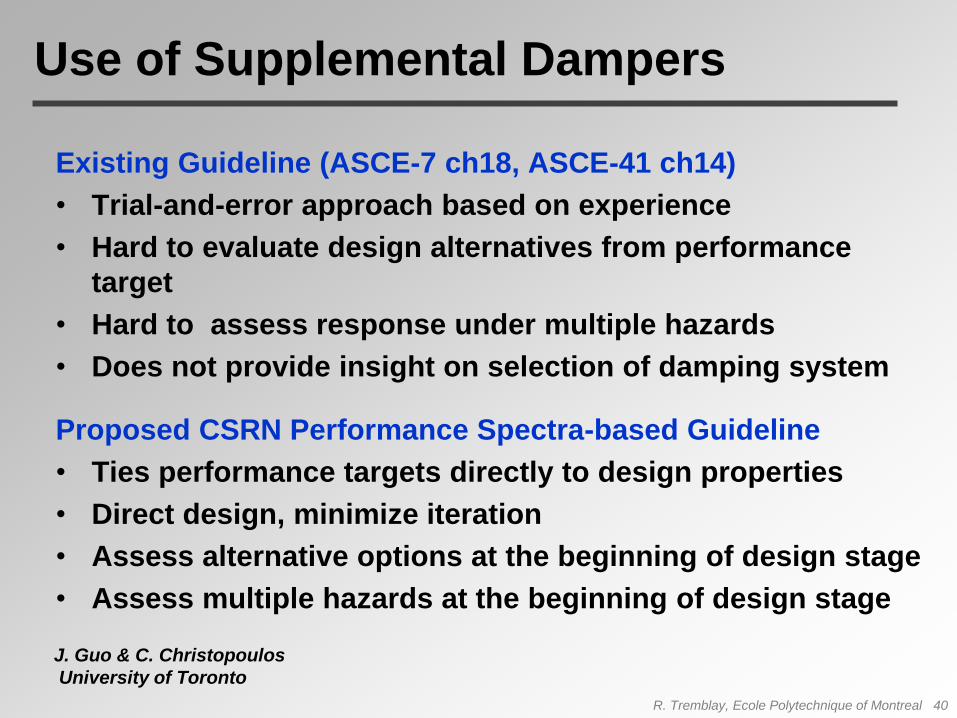
Use of Supplemental Dampers
Existing Guideline (ASCE-7 ch18, ASCE-41 ch14)
• Trial-and-error approach based on experience
• Hard to evaluate design alternatives from performance
target
• Hard to assess response under multiple hazards
• Does not provide insight on selection of damping system
Proposed CSRN Performance Spectra-based Guideline
• Ties performance targets directly to design properties
• Direct design, minimize iteration
• Assess alternative options at the beginning of design stage
• Assess multiple hazards at the beginning of design stage
J. Guo & C. Christopoulos
University of Toronto
R. Tremblay, Ecole Polytechnique of Montreal 40

P-Spectra Procedure Overview
• Using basic building properties, evaluate damping
variables that gives desired performance from
performance spectra
• Transform performance spectra solution to MDOF
• Verify design using NLTHA (expected to be close to
target)
R. Tremblay, Ecole Polytechnique of Montreal 41

Performance Spectra
R. Tremblay, Ecole Polytechnique of Montreal 42
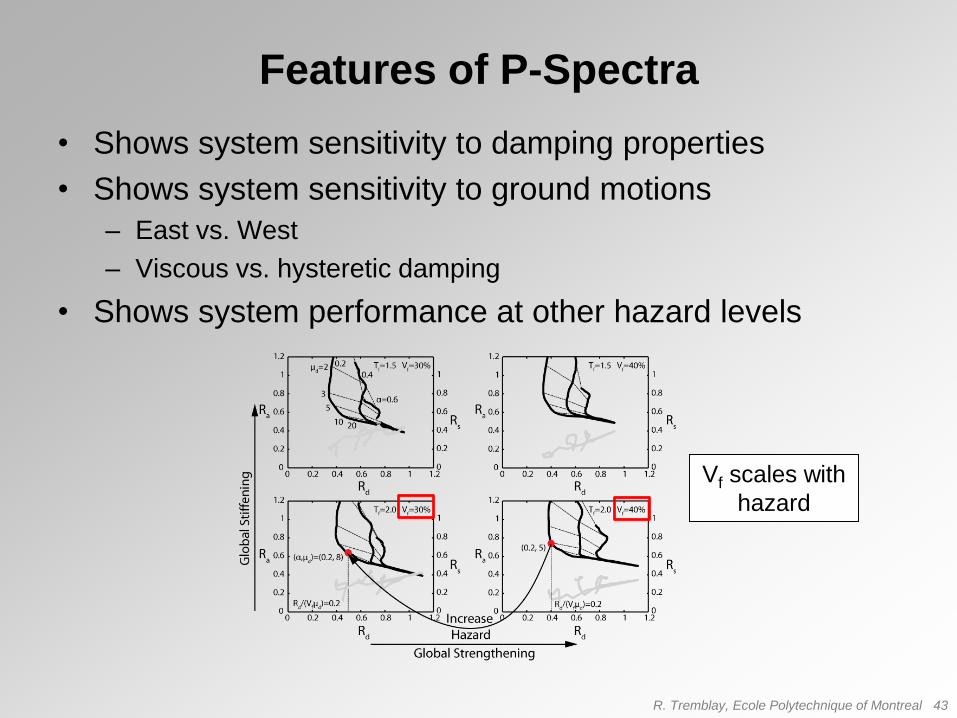
Features of P-Spectra
• Shows system sensitivity to damping properties
• Shows system sensitivity to ground motions
– East vs. West
– Viscous vs. hysteretic damping
• Shows system performance at other hazard levels
Vf scales with
hazard
R. Tremblay, Ecole Polytechnique of Montreal 43

0 0.2 0.4 0.6 0.8 10
0.2
0.4
0.6
0.8
1
1.2
1.4
1.6
1.8
Normalized Displacement, Rd
No
rmal
ized
Bas
e S
hea
r, R
v
Generic Hysteretic Damping Performance Spectrum
Specific Tf
Specific Vf
No
rmalized
Resid
ual D
rift, Rs
Increasing values ofdamper ductility, m
d
Increasing values ofratio of unbraced tobraced stiffness, a
Values of normalizedresidual drift ratios for different valuesof a
R. Tremblay, Ecole Polytechnique of Montreal 44

Conclusions
R. Tremblay, Ecole Polytechnique of Montreal 45
• Several Challenges in the Development
of Guidelines
• Braces, Brace Connections & Columns
may be Critical in CBFs
• Connections Critical in PR MRFs
• Ductiles Fuses Proposed to Enhance
the Performance of CBFs
• Effective Design Method Proposed for
Supplemental Damping


