Page 1
engineering your designs www.pro-sim.com
SIMULATED DESIGNED DELIVERED
[email protected]
SEISMIC EVALUATION OF
EQUIPMENTS FOR
NUCLEAR POWER PLANT APPLICATIONS
Pradeep S
30 May 2016, IISc Bangalore
Page 2
engineering your designs www.pro-sim.com 2
Types of Seismic Vibrations
Natural Events
•Earthquakes
•Volcanoes
•Tsunami
•Microseisms
Man-made events
•Explosions
•Reservoir seismicity
•Rock burst (mines)
•Induced seismicity
•Cultural noise
Significance
Constant updating of load spectra, evolution of standards, regulations,
rules and calculation methods has increased the importance of seismic
evaluation of NPP structures.
Page 3
engineering your designs www.pro-sim.com
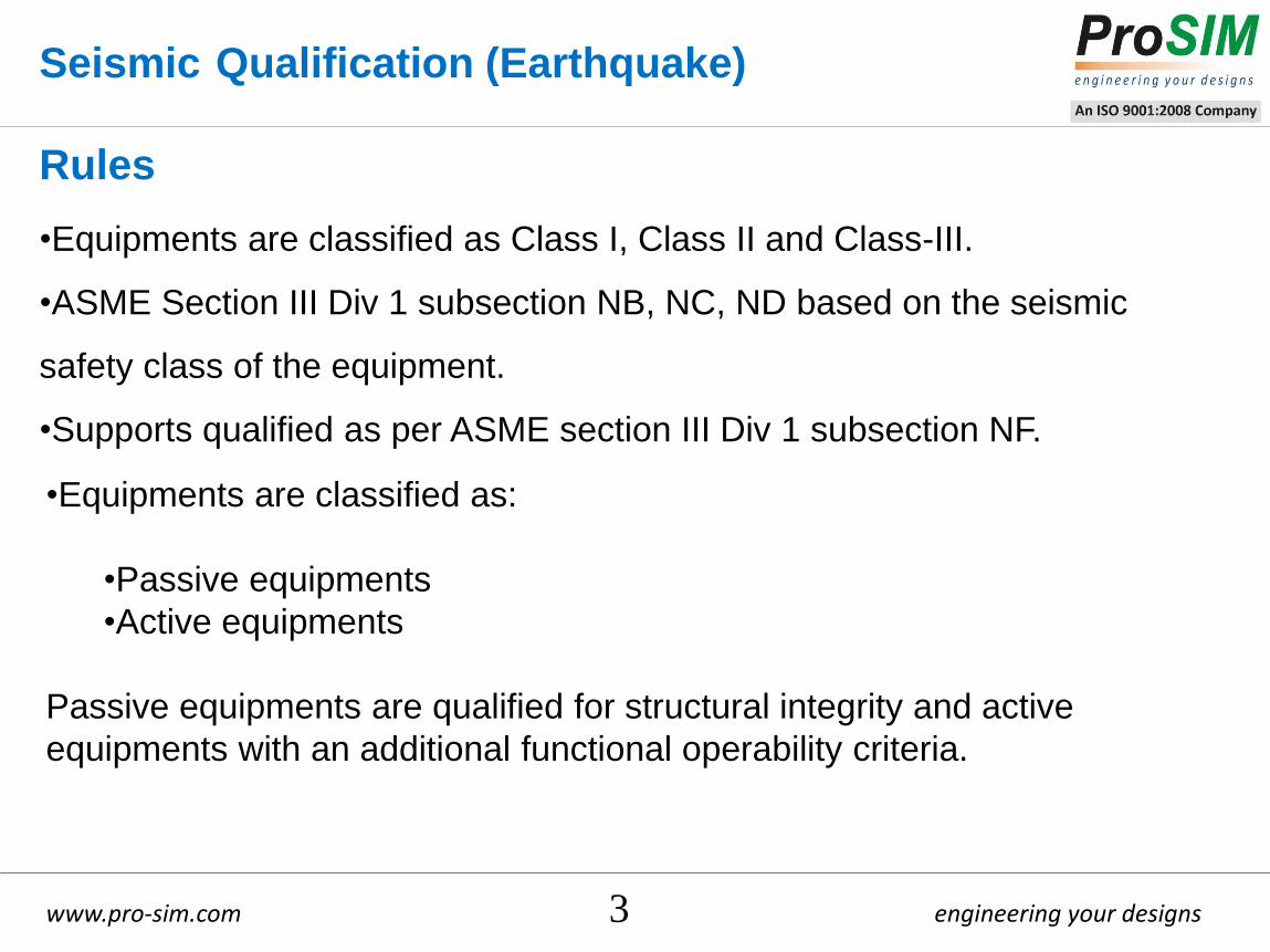
Seismic Qualification (Earthquake)
•Equipments are classified as Class I, Class II and Class-III.
•ASME Section III Div 1 subsection NB, NC, ND based on the seismic
safety class of the equipment.
•Supports qualified as per ASME section III Div 1 subsection NF.
Rules
3
•Equipments are classified as:
•Passive equipments
•Active equipments
Passive equipments are qualified for structural integrity and active
equipments with an additional functional operability criteria.
Page 4
engineering your designs www.pro-sim.com 4
TYPICAL FLOOR RESPONSE SPECTRA
•Response Spectrum Method
•Time history
•Equivalent static method
Methods
Page 5
engineering your designs www.pro-sim.com 5
Individual loads to be considered :
• Dead Weight
• Internal Pressure
• External Pressure
• Temperature
• Nozzle Loads (from piping systems)
• Response spectra (OBE and SSE)
Typical loads
Design/
Service level Load combination
Stress limits
(Class-1) (NB)
(Class-2 & 3)
(NC & ND)
Design condition Dead weight + Design Pressure +
Nozzle loads
σm ≤ 1.0 S, σl ≤ 1.5 S
(σm or σl) + σb ≤ 1.5 S σm ≤ 1.0 S
(σm or σl) + σb ≤ 1.5 S Service Level A
Operating Pressure + Thermal
(operating temp) + Nozzle Loads σm/σl + σb + Q ≤ 3S
σm/σl + σb + Q + F = S
U<1 for fatigue Service Level B
Dead weight + Design Pressure +
Thermal (operating temp) + Nozzle
loads + OBE
σm ≤ 1.1 S
(σm or σl) + σb ≤ 1.65 S
Service Level C Dead weight + Design Pressure +
Nozzle loads + SSE
σm ≤ 1.2S
σl ≤ 1.8S
(σm or σl) + σb ≤ 1.8 S
σm ≤ 1.5 S
(σm or σl) + σb ≤ 1.8 S
σm = Generalized membrane stress
σl = Localized membrane stress
σb = Bending stress
S = Allowable stress
U = Cumulative usage factor
Q, F = Secondary and peak stress
and load combination
Page 6
engineering your designs www.pro-sim.com
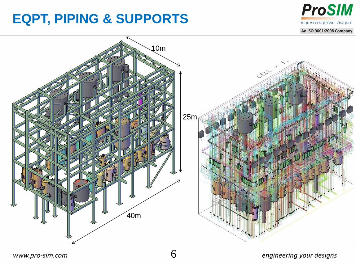
EQPT, PIPING & SUPPORTS
6
25m
40m
10m
Page 7
engineering your designs www.pro-sim.com 7
CABLE TRAY SUPPORT STRUCTURE
27 m
3 m
INITIAL DESIGN
FINAL DESIGN
Page 8
engineering your designs www.pro-sim.com
4200 KW DG SET
8
Parts considered for
qualification:
- Base frame (skid)
- Engine crank case
- Alternator assembly
- Crank shaft
- Turbocharger support
- Turbocharger
- Fly wheel
- Flexible coupling
- Oil sump
•Allowable stress limits of
the material as per
manufacturer’s standard
engineering practice.
•Functional operability
checked
Page 9
engineering your designs www.pro-sim.com
4.2 MW DG SET
Transverse forces on bearings
Lateral forces on cylinder
Piston force - Axial
9
Page 10
engineering your designs www.pro-sim.com
Load-1 = Engine dynamic forces
Load-2 = Alternator normal torque
Load-3 = Self/Dead weight
Load-4 = Loads due to seismic condition (OBE)
Load-5 = Loads due to seismic condition (SSE)
Load-6 = Short circuit load
LOAD COMBINATION FOR QUALIFICATION
•LC-1 = Loads under normal running condition
= Load-1+ Load-2 + Load-3
•LC-2 = Engine running + seismic (OBE)
= LC-1 + Load-4
•LC-3 = Engine running + seismic (SSE)
= LC-1 + Load-5
•LC-4 = Abnormal running condition = LC-1 + Load-6
10
LOADS AND COMBINATIONS (4.2 MW DG SET)
Alternator Load Application
Page 11
engineering your designs www.pro-sim.com
Sloshing inside a tank (details)
11
•Eigen value analysis with missing mass
correction
•Dynamic analysis carried out for sloshing effects
•Housner model used to adequately represent
the behavior
•Shell qualified as per ASME Sec III, ND
•Supports qualified as per ASME Sec III, NF
•Embedded plate size checks
•Weld adequacy checks
•impulsive mass, mi
•convective mass, mc
•mass of water, mw
•height of mi from bottom, hi
•height of mc from bottom, hc
•maximum height of fluid, h
•spring stiffness, Kc
Sloshing effect modeling
Page 12
engineering your designs www.pro-sim.com 12
SADDLE SUPPORTED TANKS
•Overall length of tank: 6202mm
•Outer diameter: 2324mm
Page 13
engineering your designs www.pro-sim.com 13
•Visited site (RAPP) to check availability of usable EPs and
area around the building
•Designed the tower from scratch
•Strength design of columns.
•Strength design of bracings.
•Strength design of stacks.
•Strength design of structure foundation bolts.
•Strength design of structure base plate and gussets.
•Pull out shear failure mode of foundation.
LATTICE TOWER SUPPORTED CHIMNEY
3 exhaust pipes entering the tower Silencer arrangement on the roof Complete lattice tower
Page 14
engineering your designs www.pro-sim.com 14
CONCLUSION
Seismic qualification is mandatory for all equipments before they are
installed in a Nuclear Facility.
ASME Sec III, is applicable for qualification based on the safety class of the
equipment.
FE Software provides a comprehensive assessment for qualification.
We have developed macros & scripts for load combination and qualification.
Successfully completed >45 projects on seismic qualification.
DAE entities & their EPCs: NPCIL, IGCAR, BARC-NRB and Punj Lloyd/
L&T
ITER, France through AMEC Nuclear, UK.
Page 15
engineering your designs www.pro-sim.com 15
ProSIM R&D Pvt Ltd #4, 1st B Main, 1st N Block, Rajajinagar, Bangalore – 560010
Ph: +91 80 23323020, Fax: +91 80 23323304
SIMULATED DESIGNED DELIVERED


![[INIS] Earthquake resistance of nuclear power plants · Proceedings of the Post-SMiRT conference seminar on advances in seismic design of structures, systems and components of nuclear](https://static.documents.pub/doc/80x56/5f0d65e47e708231d43a27d6/inis-earthquake-resistance-of-nuclear-power-plants-proceedings-of-the-post-smirt.jpg)

