Seismic performance of two water-storage dams during the Mw 6.6 Lake Grassmere Earthquake in August 2013 2017 NZSEE Conference R. Amigh Engineering Geology Ltd, Auckland, New Zealand. M. Ghamgosar The School of Civil Engineering, The University of Queensland, Australia. C. Wu Engineering Geology Ltd, Auckland, New Zealand. ABSTRACT: On 16 August 2013, a magnitude Mw 6.6 earthquake occurred 35 km south- east of Blenheim in the South Island, New Zealand. It was a shallow earthquake which had a hypocentre at a depth of 8 km below ground. The epicentre of the earthquake is at about 9 km southeastern of the Seddon. This paper discusses the seismic performance of two water storage dams used to store water for irrigation purposes. The dams are located within 10 km of the earthquake epicentre. They are earth-fill embankments, each about 12 m high. The dams were designed and constructed within the last nine years. Relatively large deformation, cracking and slumping occurred as a result of the earthquake. Post-earthquake studies comprising surveys of the embankments and geotechnical investigations were undertaken to evaluate the possible cause of damage and to provide remediation plan. The results indicate poor construction with some design deficiencies contributed to the damage. 1 INTRODUCTION Earthquakes are one of the most destructive natural events. They can result in significant physical and environmental damage and financial and human losses. Earth-fill embankments generally have a good performance record when subjected to strong earthquake ground motion, but there are examples when significant damage, and in some rare cases failure, have occurred. New Zealand is located at the boundary between the Australian and Pacific tectonic plates. The plates collide obliquely resulting in a complex interaction. Movement between the plates is accommodated by subduction zones and large active faults which result in the generation of thousands of earthquakes every year in New Zealand. Many of these earthquakes are too small to be felt. Major earthquakes occur less frequently but there have been some major events, for example, the 1855 Wairarapa (Mw 7.6), the 1931 Hawke’s Bay (Mw 7.8), the 2013 Christchurch (Mw 6.6) earthquakes and the recent 2016 Kaikoura Earthquake (Mw 7.8). On 16 August 2013, a Mw 6.6 earthquake occurred 35 km south-east of Blenheim in the South Island, New Zealand. It occurred at a depth of 8 km, and was centered beneath Lake Grassmere around 9 km south-east of the town of Seddon. The earthquake caused some damage to residential properties and infrastructure of the region. Two water storage dams, referred to as Dams 1 and 2 due to confidentiality reasons, situated within 10 km of the earthquake epicentre were damaged by the ground shaking. Relatively large deformation, cracking and slumping occurred as a result of the earthquake. The epicentre of the earthquake and the general area of the two water storage dams are shown in Figure 1. The earthquake-induced damage of these two dams has been remediated following the Lake Grassmere earthquake. The seismic performance of the two dams has further been examined by the recent Kaikoura Earthquake.
Transcript
Seismic performance of two water-storage dams during
the Mw 6.6 Lake Grassmere Earthquake in August
2013
2017 NZSEE Conference
R. Amigh
Engineering Geology Ltd, Auckland, New Zealand.
M. Ghamgosar
The School of Civil Engineering, The University of Queensland, Australia.
C. Wu
Engineering Geology Ltd, Auckland, New Zealand.
ABSTRACT: On 16 August 2013, a magnitude Mw 6.6 earthquake occurred 35 km south-
east of Blenheim in the South Island, New Zealand. It was a shallow earthquake which had
a hypocentre at a depth of 8 km below ground. The epicentre of the earthquake is at about
9 km southeastern of the Seddon. This paper discusses the seismic performance of two
water storage dams used to store water for irrigation purposes. The dams are located within
10 km of the earthquake epicentre. They are earth-fill embankments, each about 12 m high.
The dams were designed and constructed within the last nine years. Relatively large
deformation, cracking and slumping occurred as a result of the earthquake. Post-earthquake
studies comprising surveys of the embankments and geotechnical investigations were
undertaken to evaluate the possible cause of damage and to provide remediation plan. The
results indicate poor construction with some design deficiencies contributed to the damage.
1 INTRODUCTION
Earthquakes are one of the most destructive natural events. They can result in significant physical and
environmental damage and financial and human losses. Earth-fill embankments generally have a good
performance record when subjected to strong earthquake ground motion, but there are examples when
significant damage, and in some rare cases failure, have occurred. New Zealand is located at the
boundary between the Australian and Pacific tectonic plates. The plates collide obliquely resulting in a
complex interaction. Movement between the plates is accommodated by subduction zones and large
active faults which result in the generation of thousands of earthquakes every year in New Zealand.
Many of these earthquakes are too small to be felt. Major earthquakes occur less frequently but there
have been some major events, for example, the 1855 Wairarapa (Mw 7.6), the 1931 Hawke’s Bay (Mw
7.8), the 2013 Christchurch (Mw 6.6) earthquakes and the recent 2016 Kaikoura Earthquake (Mw 7.8).
On 16 August 2013, a Mw 6.6 earthquake occurred 35 km south-east of Blenheim in the South Island,
New Zealand. It occurred at a depth of 8 km, and was centered beneath Lake Grassmere around 9 km
south-east of the town of Seddon. The earthquake caused some damage to residential properties and
infrastructure of the region. Two water storage dams, referred to as Dams 1 and 2 due to confidentiality
reasons, situated within 10 km of the earthquake epicentre were damaged by the ground shaking.
Relatively large deformation, cracking and slumping occurred as a result of the earthquake. The
epicentre of the earthquake and the general area of the two water storage dams are shown in Figure 1.
The earthquake-induced damage of these two dams has been remediated following the Lake Grassmere
earthquake. The seismic performance of the two dams has further been examined by the recent Kaikoura
Earthquake.
2
Figure 1. Map showing the epicenter of 2013 Grassmere Lake Earthquake and the general area of the
two earthquake affected dams
2 WATER STORAGE DAMS CASE HISTORIES
The dams are earth-fill embankments, each about 12m high. Dam 1 had a very small catchment and
formed a small pond into which water was pumped. The dams were designed and constructed within the
last nine years. Both dams were constructed and raised in two stages. In the case of Dam 1, the raising
was undertaken without any design advice. Stage 1 of Dam 1 was designed with a central core of
weathered mudstone with shoulders of low plasticity clayey silts (derived from soils of loess origin).
Dam 2 was designed as a homogeneous embankment constructed from weathered mudstone. Both dams
included a chimney drain. Dam 1 was raised by placement of fill over the upstream shoulder. Dam 2
was raised by placement of fill above the crest of Stage 1 which was broad enough to allow this, although
the fill was placed at a steep angle. Raising of the embankments (i.e. Stage 2) took place within several
months of completion of Stage 1. Dams 1 and 2 were raised by 1 m and 3 m respectively. The materials
used for the Stage 2 raising were low plasticity slightly clayey, sandy silts (derived from soils of loess
origin). Stage 1 construction was carried out under some level of supervision, supplemented with quality
control testing. In comparison, Stage 2 fill placement involved no supervision or control testing. The fill
material associated with Stage 2 was a low plasticity slightly clayey, sandy silt (loess). It is postulated
that during the earthquake excess pore water pressure (EPWP) was generated, resulting in a significant
reduction in strength.
Both dams had also some design deficiencies. For example, the chimney drain was not extended and
raised beyond Stage 1. Moreover. The spillway for Dam 1 had not been constructed. Dam 2 had a service
spillway but was constructed too high, and so the freeboard was only 0.3m.
At the time of the Lake Grassmere Earthquake, the reservoir water level in both dams was only about
0.3m below crest level. Consequently, the Stage 2 fill was saturated and softened due to the lack of
proper conditioning and compaction and because the chimney drain had not been raised. Deformation,
slumping and cracking occurred as a result of the earthquake. At Dam 1, cracks up to 400mm wide
happened in the upstream shoulder and crest as a resulting of slumping of the upstream shoulder at high
elevations as indicated in Figure 2. At Dam 2, longitudinal cracks were evident in the downstream
shoulder close to the crest. Longitudinal cracks and slumping were evident in the upstream shoulder at
high elevations. Transverse cracks occurred near the eastern and western ends of the dam crest. Cracks
were also evident on the slopes surrounding the reservoir. Figure 3 shows upstream slumping and a
transverse crack at Dam 2.
3
Another factor is that the Lake Grassmere earthquake included some strong aftershocks. It is possible
that the observed displacements are a combination of the cumulative effects of the main shock and
aftershocks. The sensitive nature of the fill, i.e. being from loess origin, and the poor standard of
compaction may have resulted in additional softening due to the development of excess pore pressures
in the fill.
Figure 2. Dam 1: Lateral spreading cracks up to 400mm over (a) upstream shoulder and (b) crest
following 2013 Grassmere Lake Earthquake
Post-earthquake investigations were undertaken to assess the condition of the embankments. Test pits
were excavated in the crests and upstream shoulders of the dams. Hand auger boreholes were also drilled
in the upstream shoulders of both dams. The investigation confirmed the fill associated with Stage 2 was
highly saturated with shear vane strengths generally less than 50kPa. These are strength measured
several months after the earthquake. The strengths could have been lower during and immediately after
the earthquake shaking.
Figure 3. Dam 2: (a) transverse cracks up to 100mm at eastern and western ends of dam crest (b)
longitudinal cracking and slumping up to 200mm along upstream face of dam
3 OVERVIEW OF EARTHQUAKE-RESISTANT DESIGN PROCEDURES FOR EARTH
DAMS
The design of dams in seismic regions requires determination of seismic loads and assessment of the
4
seismic response, stability and deformations. Guidelines published by the International Commission on
Large Dams (ICOLD) provide guidance on the design of dams. ICOLD Bulletin 72 (ICOLD 2010)
provides guidance on seismic design. Methods for analysing the seismic performance of embankment
dams have advanced with time. Simple pseudo-static methods have been replaced by methods that allow
for the dynamic response of embankments and estimation of displacements (transient and permanent).
These methods vary in sophistication from simplified methods to time-history analyses. The simplified
methods based on the Newmark sliding block (Newmark 1965) concept are widely applied in the
industry. Dynamic analysis using finite element or finite difference methods is also used but generally
only for dams where the consequences of failure could be significant. Such analyses require more
detailed knowledge of material properties and selection of appropriate acceleration time histories.
Current best practice for the earthquake-resistant design of an embankment dam includes the following
steps;
Assessment of the site seismic hazard (i.e. estimation of expected earthquake ground motions
and potential for fault rupture)
Undertake site investigation and laboratory testing
Select ground motion design parameters for seismic stability analysis
Undertake seismic and deformation analyses
Develop appropriate design details (e.g. embankment geometry and zones, material
characteristics and filter/drainage features)
Prepare appropriate specifications and construction methodology
The New Zealand Society on Large Dams (NZSOLD) provides general guidelines for dam design in
New Zealand (NZSOLD 2015). Moreover, ICOLD provides a number of Bulletins that cover assessment
of seismic hazard, design, construction and operation (ICOLD 2010).
4 DESIGN STANDARD AND ACTUAL SEISMIC HAZARD
The design standards adopted for the remediation work are in accordance with the procedure outlined
in Section 3. The dams are located in the Marlborough region which encompasses the northeast end of
the South Island. It is one of the most seismically active regions in New Zealand. Movement between
the Australian and Pacific tectonic plates is accommodated by a number of the main strike-slip faults
(Kerr et al. 2003). They include the Awatere, Wairau (northern extension of the Alpine Fault) and
Clarence Faults. There are also smaller faults including the London Hill, Hog Swamp and the Medway.
The Maximum Credible Earthquake (MCE) governing seismic design for the area in which Dams 1 and
2 are located is generally the Awatere Fault. It is a strike-slip fault which has a maximum moment
magnitude (Mw) of 7.5 and a recurrence interval of 1,000-3,000 years (Stirling et al. 1998). NZSOLD
provides general guidelines on selecting ground motion parameters for dam design in New Zealand
(NZSOLD 2015). It is recommended that the Operating Basis Earthquake (OBE) be based on ground
motion with an Annual Exceedance Probability (AEP) of 1 in 150. The Safety Evaluation Earthquake
(SEE) for dams with High Potential Impact Classification (PIC) is recommended to be based on the 84th
percentile level for the Controlling Maximum Earthquake (CME) or ground motion with a 1 in 10,000
AEP derived from a probabilistic seismic hazard study. For Low and Medium PIC dams, lower levels
of ground motion can be adopted. Dams 1 and 2 are Low PIC. For such dams NZSOLD recommends
the SEE be taken equal to the 50th percentile level for the Controlling Maximum Earthquake (CME).
This is the earthquake that is capable of producing the strongest level of ground motion at the site. This
is a ground motion of at least 1 in 500 AEP but need not exceed the 1 in 1,000 AEP derived from a
probabilistic seismic hazard study.
The 2013 Cook Strait/Lake Grassmere earthquake sequence occurred during July and August, followed
by numerous aftershocks. Ground motions were recorded by two strong motion recorders, Ward Fire
Station (WDFS) and Seddon Fire Station (SEDS) located at a similar distance from the earthquakes as
the dam sites. Ground conditions at WDFS are Subsoil Class C in accordance with NZS1170.5 (NZS
5
2004). The subsoil condition at SEDS is also Subsoil Class C based on Bradley and Cubrinovsky (2011).
Dams 1 and 2 are founded on weathered mudstone which is equivalent to Subsoil Class B in accordance
with NZS1170.5. Generally speaking, ground motions recorded at WDFS and SEDS could be expected
to be greater than the ground motions at the dam sites. The recordings at the strong motion recorders
provide an insight to the level of ground motion possibly experienced at the dam sites during
earthquakes. A comparison between the design levels of ground motion for the dams and the recordings
from WDFS and SEDS during the Lake Grassmere Earthquake are shown in Figure 4. The ground
motions recorded at WDFS and SEDS exceed the SEE design level of ground motion (1 in 500 AEP)
for spectral periods less than about 1 second. The ground motions recorded at WDFS and SEDS during
the Kaikoura Earthquake are shown in Figure 5. Comparing Figures 4 and 5 show that the horizontal
ground motion during the Kaikoura Earthquake are generally greater than the Lake Grassmere
Earthquake at these strong motion recorders.
Figure 4. Comparison of the design level of ground motion for a low PIC dam and the strong motion
recordings during Lake Grassmere Earthquake
Figure 5. Comparison of the design level of ground motion for a low PIC dam and the strong motion
recordings during Kaikoura Earthquake
6
5 REMEDIATION
There are various common methods of the seismic rehabilitation of earth dams including measures such
as berms and buttresses, excavate and replace, in-situ densification and strengthening, increased
freeboard, drainage, etc. (Marcuson et al. 1996). Both dams were remediated following the earthquake
s with the works undertaken in 2014. The design for the remedial works was carried out in accordance
with the procedure outlined in Section 3. Ground motion design parameters were also selected for
seismic stability analysis of the dams as discussed in Section 4. A combination approach, including
“excavate and replace”, “increased freeboard” and “berms and buttresses” methods, was adopted to
remediate the earthquake affected dams as discussed below.
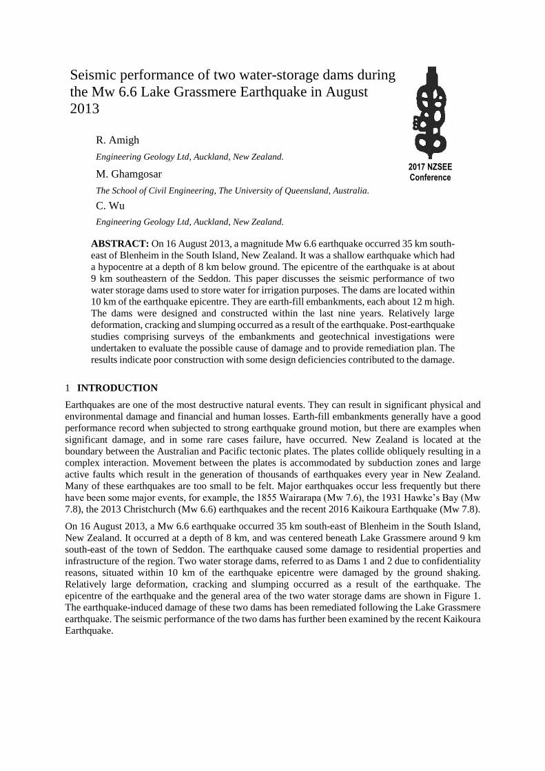
The remediation work for both dams was initiated by dewatering the reservoirs. Both dams were
constructed back to their original design crest level. In the case of Dam 1, this was less than the
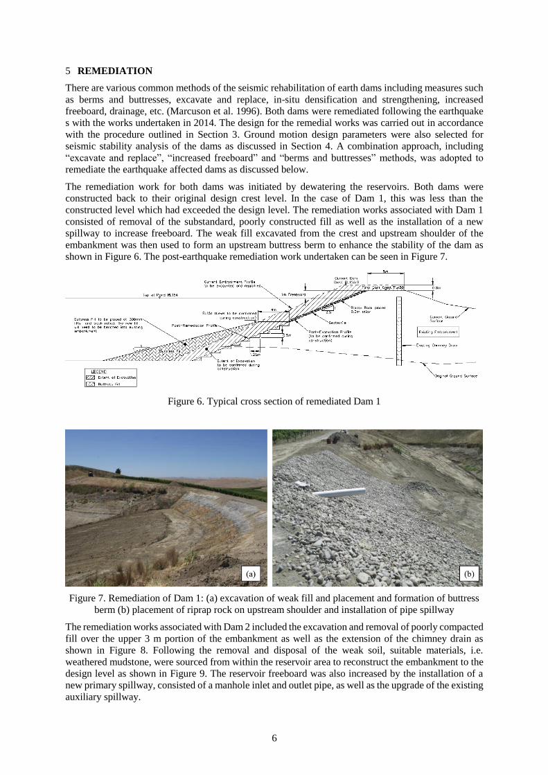
constructed level which had exceeded the design level. The remediation works associated with Dam 1
consisted of removal of the substandard, poorly constructed fill as well as the installation of a new
spillway to increase freeboard. The weak fill excavated from the crest and upstream shoulder of the
embankment was then used to form an upstream buttress berm to enhance the stability of the dam as
shown in Figure 6. The post-earthquake remediation work undertaken can be seen in Figure 7.
Figure 6. Typical cross section of remediated Dam 1
Figure 7. Remediation of Dam 1: (a) excavation of weak fill and placement and formation of buttress
berm (b) placement of riprap rock on upstream shoulder and installation of pipe spillway
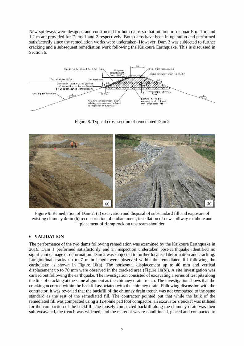
The remediation works associated with Dam 2 included the excavation and removal of poorly compacted
fill over the upper 3 m portion of the embankment as well as the extension of the chimney drain as
shown in Figure 8. Following the removal and disposal of the weak soil, suitable materials, i.e.
weathered mudstone, were sourced from within the reservoir area to reconstruct the embankment to the
design level as shown in Figure 9. The reservoir freeboard was also increased by the installation of a
new primary spillway, consisted of a manhole inlet and outlet pipe, as well as the upgrade of the existing
auxiliary spillway.
7
New spillways were designed and constructed for both dams so that minimum freeboards of 1 m and
1.2 m are provided for Dams 1 and 2 respectively. Both dams have been in operation and performed
satisfactorily since the remediation works were undertaken. However, Dam 2 was subjected to further
cracking and a subsequent remediation work following the Kaikoura Earthquake. This is discussed in
Section 6.
Figure 8. Typical cross section of remediated Dam 2
Figure 9. Remediation of Dam 2: (a) excavation and disposal of substandard fill and exposure of
existing chimney drain (b) reconstruction of embankment, installation of new spillway manhole and
placement of riprap rock on upstream shoulder
6 VALIDATION
The performance of the two dams following remediation was examined by the Kaikoura Earthquake in
2016. Dam 1 performed satisfactorily and an inspection undertaken post-earthquake identified no
significant damage or deformation. Dam 2 was subjected to further localised deformation and cracking.
Longitudinal cracks up to 7 m in length were observed within the remediated fill following the
earthquake as shown in Figure 10(a). The horizontal displacement up to 40 mm and vertical
displacement up to 70 mm were observed in the cracked area (Figure 10(b)). A site investigation was
carried out following the earthquake. The investigation consisted of excavating a series of test pits along
the line of cracking at the same alignment as the chimney drain trench. The investigation shows that the
cracking occurred within the backfill associated with the chimney drain. Following discussion with the
contractor, it was revealed that the backfill of the chimney drain trench was not compacted to the same
standard as the rest of the remediated fill. The contractor pointed out that while the bulk of the
remediated fill was compacted using a 12-tonne pad foot compactor, an excavator’s bucket was utilised
for the compaction of the backfill. The loosely compacted backfill along the chimney drain was then
sub-excavated, the trench was widened, and the material was re-conditioned, placed and compacted to
8
adequate standard using a 12-tonne pad foot compactor. The post-earthquake remediation work
undertaken for Dam 2 is shown in Figure 10 (c) and (d).
Figure 10. Dam 2: (a) longitudinal cracking with horizontal, (b) vertical displacements of up to 40mm
and 70mm respectively, along chimney drain trench, (c) and (d) post-earthquake remediation work
(2016 Kaikoura Earthquake)
7 CONCLUSIONS
Seismic performance of two water storage dams was assessed and evaluated. Both dams were subject
to relatively large deformation, cracking and slumping following the 2013 Lake Grassmere Earthquake.
Post-earthquake assessment consisting of a review of the dam designs and construction, site
investigation and analyses was undertaken. The assessment indicated that the main causes of the poor
seismic performance were poor construction (inadequate conditioning and compaction) and the lack of
supervision. Both dams have since been remediated and are back in operation. Following 2016 Kaikoura
Earthquake, Dam 2 was subjected to further localised deformation. This is due to inadequate compaction
of the backfill for the chimney drain trench. Although, Dam 1 performed satisfactorily during the recent
earthquake. One of the authors of this paper has been involved in the design and construction of a number
of water storage dams in the general area of the affected dams. Post-earthquake inspections carried out
indicated that most of those dams performed satisfactorily with no significant deformation or cracking
during both 2013 Lake Grassmere and 2016 Kaikoura Earthquake Earthquakes.
8 ACKNOWLEDGMENT
The authors would like to acknowledge the support provided by Engineering Geology Ltd and comments
and suggestions by Trevor Matuschka.
9 REFERENCES
Bradley, B.A. & Cubrinovski, M. (2011). Near-source strong ground motions observed in the 22 February 2011
Christchurch earthquake. Seismological Research Letters, 82(6), pp.853-865.
ICOLD. (2010). Selecting Seismic Parameters for Large Dams Guidelines, Available at: http://www.icold-
cigb.net/.
Kerr, J., Nathan, S., Van Dissen, R., Webb, P., Brunsdon, D. & King, A. (2003). Planning for development of land
on or close to active faults. Wellington, Ministry of the Environment.
Marcuson III, W.F., Hadala, P.F. & Ledbetter, R.H. (1996). Seismic rehabilitation of earth dams. Journal of geotechnical engineering, 122(1), pp.7-20.
Mejia, L., Gillon, M., Walker, J. & Newson, T. (2002). Criteria for developing seismic loads for the safety
evaluation of dams of two New Zealand owners. ANCOLD Bulletin, pp.65-74.
9
Newmark, N.M. (1965). Effects of Earthquakes on Dams and Embankments. Géotechnique, 15(2), pp.139–160.
NZS 1170.5. (2004). Structural Design Actions, Standards New Zealand, Part 5: Earthquake actions New Zealand.
NZSOLD. (2015). New Zealand Dam Safety Guidelines, New Zealand Society on Large Dams ISBN:978-0-
908960-65-1.
Stirling, M.W., Wesnousky, S.G. & Berryman, K.R. (1998). Probabilistic seismic hazard analysis of New Zealand.
New Zealand Journal of Geology and Geophysics, 41(4), 355-375.