journa l h omepa g e: www.elsev ier .com/ locate /precamres
eismic structure of the crust and uppermost mantle of the Capricorn andaterson Orogens and adjacent cratons, Western Australia, from passiveeismic transects
nya M. Readinga,b,∗, Hrvoje Tkalcic b, Brian L.N. Kennettb, Simon P. Johnsonc, Stephen Sheppardd,c
School of Earth Sciences and CODES Centre of Excellence, University of Tasmania, Private Bag 79, Hobart 7001, TAS, AustraliaResearch School of Earth Sciences, Australian National University, Canberra 0200, ACT, AustraliaGeological Survey of Western Australia, Department of Mines and Petroleum, Mineral House, 100 Plain Street, East Perth 6004, WA, AustraliaMineral Resources Authority, Geological Mapping and Exploration, PO Box 1906, Port Moresby 121, Papua New Guinea
r t i c l e i n f o
rticle history:eceived 27 February 2011eceived in revised form 23 June 2011ccepted 2 July 2011vailable online 14 July 2011
eywords:apricorn Orogenaterson Orogenroterozoicrustal structureassive seismiceceiver function
a b s t r a c t
The seismic structure of the Proterozoic Capricorn and Paterson Orogens and adjacent Archaean Yil-garn and Pilbara Cratons, Western Australia, is determined using a passive seismic approach. We userecordings of distant earthquakes made along two transects of 3-component broadband stations. Thestations were deployed for approximately 1 year (mid 2006–2007) during which time 70 earthquakeswere recorded at each station with a suitable signal to noise ratio for receiver function analysis and hencethe S wavespeed profiles of the crust and uppermost mantle beneath each recording station are deter-mined. We investigate the deep crustal constraints on terrane boundary locations, the patterns of seismicdiscontinuities in the crust, and the variations in the depth and character of the Moho. This broad-scaleinformation regarding the present day crustal architecture, and hence the crustal evolution, of WesternAustralia, complements previous surface geological and other geophysical studies. Western Australia isan exceptionally large, well preserved region of ancient crust and hence this work also adds to the bodyof knowledge regarding Proterozoic orogenic processes in general. The new passive seismic work showsa region of double crust or upper mantle discontinuities beneath the Glenburgh Terrane, adjacent to the
northwest Yilgarn Craton. The upper crust of the orogens is always layered whereas the cratons have asimple upper crust. Both the Capricorn and Paterson Orogens are characterised by deeper Moho disconti-nuities with a lesser wavespeed contrast than the very sharp discontinuity observed beneath the adjacentPilbara and Yilgarn Cratons. This is consistent with the weaker orogenic crust of the Capricorn and Pater-son Orogens accommodating most of the horizontal deformation during assembly and reworking of theWest Australian Craton while the Pilbara and Yilgarn Cratons acted as rigid crustal blocks.
. Introduction
Passive seismic techniques provide a complementary approacho active seismic, and surface geological and geochemical methods,n determining the architecture of the continental lithosphere. Ifctive seismic (reflection/refraction) data are not available, passiveeismic methods provide a relatively easy and cost-effective recon-aissance determination of Moho depth and character, the depth
nd character of other discontinuities, and seismic wavespeed fea-ures within the crust (Darbyshire, 2003; Reading, 2006). In bettertudied regions, passive techniques, such as receiver function anal-
∗ Corresponding author at: School of Earth Sciences and CODES Centre of Excel-ence, University of Tasmania, Private Bag 79, Hobart 7001, TAS, Australia.el.: +61 3 6226 2477; fax: +61 3 6226 2547.
ysis, reveal broad-scale variations in the character of the crust anduppermost mantle which may not be apparent from active seismiclines (Reading et al., 2007).
This paper presents new data from more closely spaced sta-tions than previous passive seismic work carried out in WesternAustralia (Reading and Kennett, 2003; Reading et al., 2003, 2007) inthe form of receiver function determinations of S wavespeed struc-ture along two new passive seismic transects through the Capricornand Paterson Orogens of the West Australian Craton (Fig. 1). Weaim to (1) re-examine the location of terrane boundaries comparingnew constraints from deep seismic structure to existing determi-nations based on surface geology; (2) identify relict structures atdepth, with implications for tectonic history, through the pres-
ence and depth of major seismic discontinuities, and the variationand/or absence of such discontinuities along the transects; and (3)infer variations in tectonic history through the change in depth andcharacter of the Moho along the transects. Our investigations and
296 A.M. Reading et al. / Precambrian Research 196– 197 (2012) 295– 308
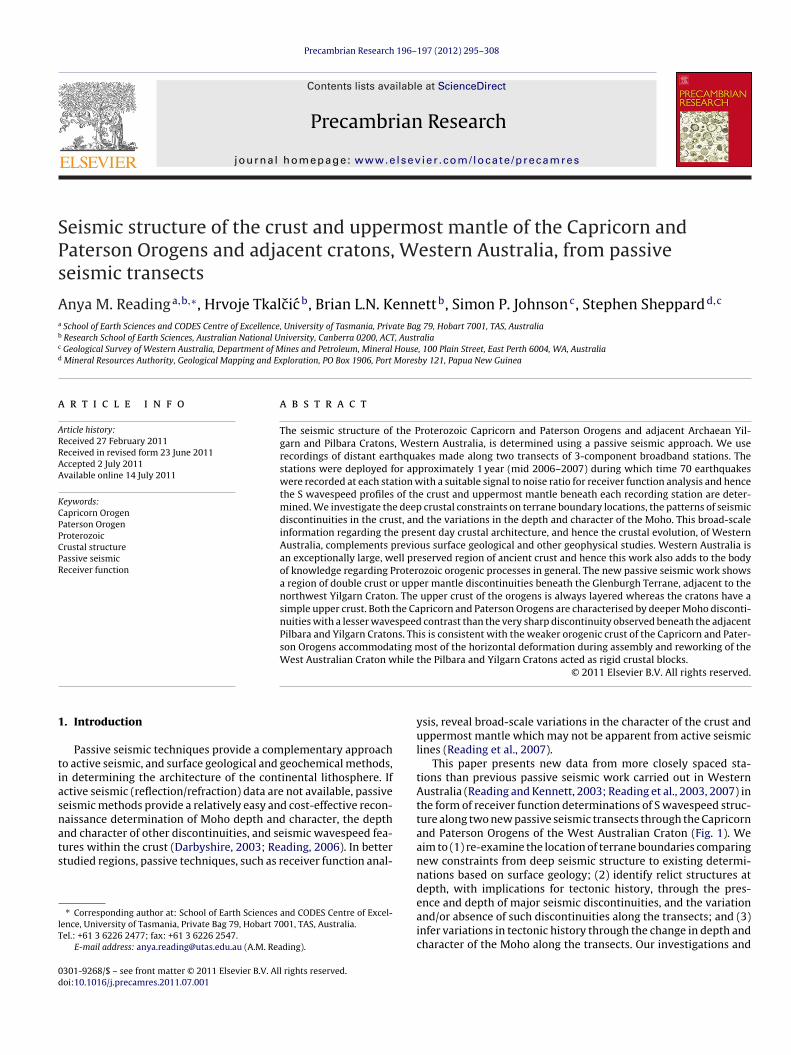
Fig. 1. Location map of northwest Western Australia. Geological provinces are shown by age (modified from Sheppard et al., 2010a). Temporary broadband seismic stationsof the CAPRA deployment (mid 2006–mid 2007) are indicated by solid stars. The permanent Global Seismic Network station located near Marble Bar (MBWA) is indicated bya solid circle. Other stations discussed by name in the text are shown as open circles. Thick lines show the limits of the Capricorn and Paterson Orogens (dashed under cover).ESZ = Errabiddy Shear Zone, YGC = Yarlarweelor Gneiss Complex, T = Telfer, M = Meekathara. Location map (top right) shows the extent of the main map as a red rectanglea nits.
Y e the Pi
ibA
1
rtTpdGNSbaC(ebfKrPdSeol(
nd the WAC (=West Australian Craton) in the context of other ancient tectonic uC = Yilgarn Craton, KC = Kimberley Craton, GC = Gawler Craton. The Tasmanides ar
n this figure legend, the reader is referred to the web version of the article.)
nferences based on deep seismic structure build on an evolvingody of knowledge on the geology and tectonic history of Westernustralia which is summarised in the following sections.
.1. The Capricorn Orogen
The Capricorn Orogen in central Western Australia (Fig. 1)ecords the joining of the Archaean Pilbara and Yilgarn Cratonso form the West Australia Craton (Cawood and Korsch, 2008;yler and Thorne, 1990). It is traversed by the longer of the twoassive seismic transects in this study. The orogen includes theeformed craton margins and a wedge of exotic crust termed thelenburgh Terrane which forms the oldest part of the Palaeo-to-eoproterozoic Gascoyne Province (Johnson et al., 2010, 2011;heppard et al., 2010b). The West Australian Craton was assem-led from three tectonic blocks during two discrete orogenies. First,ccretion or collision of the Glenburgh Terrane with the Pilbararaton occurred during the 2.21–2.14 Ga Ophthalmian OrogenyJohnson et al., 2010, 2011; Martin and Morris, 2010; Occhipintit al., 2004). The suture is buried by the Proterozoic Wyloo (Ash-urton Basin), Edmund and Collier Groups but is interpretedrom magnetotelluric (MT) and tomography data (Abdullah, 2007;ennett and Abdullah, 2011; Selway, 2008; Selway et al., 2009) tooughly coincide with the Talga Fault (Fig. 1). Second, the combinedilbara Craton–Glenburgh Terrane collided with the Yilgarn Cratonuring the 2.00–1.95 Ga Glenburgh Orogeny along the Errabiddyhear Zone (Johnson et al., 2010; Occhipinti et al., 2004; Sheppard
t al., 2010b). Following the final suturing of the craton, the historyf the Capricorn Orogen was dominated by more than one bil-ion years of episodic intracontinental reworking and reactivationSheppard et al., 2010a).
NAC = North Australian Craton, SAC = South Australian Craton, PC = Pilbara Craton,roterozoic rocks of eastern Australia. (For interpretation of the references to color
1.2. The Paterson Orogen
The Paterson Orogen is located on the northeastern fringe ofthe West Australian Craton and is interpreted to record the col-lision of the West and North Australian Cratons at approximately1.78 Ga (Smithies and Bagas, 1997). It is crossed by the shorter of thetwo passive seismic transects in this study. The orogen comprisesPalaeoproterozic to Mesoproterozoic metasedimentary and meta-igneous rocks of the Rudall Province, and unconformably overlyingNeoproterozoic sedimentary successions deposited after 1.07 Gaand before 0.65 Ga (Bagas, 2004; Cassidy et al., 2006b). The RudallProvince, which outcrops to the south of the transect comprisesmultiply deformed and metamorphosed sedimentary and igneousrocks with maximum ages of 2.02 Ga. The Rudall Province recordsdeformation associated with a major orogenic event that occurredat 1.6–1.5 Ga, after the amalgamation of the Pilbara and YilgarnCratons through the orogenic activity encompassing the marginsof the North and South Australian Cratons. Alternative models forthe nature and timing of these major events exist, e.g. Betts et al.(2002) and Payne et al. (2009).
1.3. Tectonic units of the West Australian Craton
The following is a summary of the tectonic units that make upthe West Australian Craton that are traversed by the lines of theCAPRA passive seismic array (Fig. 1).
The Pilbara Craton is composed of numerous geologically dis-
tinct terranes, the oldest of which is the East Pilbara Terrane,which is dominated by granite-greenstones with ages ranging from3.70–2.83 Ga (Van Kranendonk et al., 2007). The terrane was con-structed between 3.53 and 3.24 Ga through a series of mantle plume
n Res
eRds2w
oFFcFittBsBops
cGCwMoiuaw(ttWmWt2
C4rsTriDotbSGb
gOa(of2bw2
A.M. Reading et al. / Precambria
vents and accreted with other terranes, the Sholl, Karratha andegal Terranes (not shown in Fig. 1, see Van Kranendonk et al., 2007)uring the 3.07 Ga Prinsep Orogeny. During orogenic relaxation andlab break off, intracontinental rifting allowed the deposition of the.99–2.93 Ga De Grey Superbasin (not shown). Final cratonizationas complete by 2.83 Ga (Van Kranendonk et al., 2007).
The southern margin of the Pilbara Craton is unconformablyverlain by the late Archaean to Palaeoproterozoic 2.78–2.43 Gaortescue, Hamersley and Turee Creek Basins. The 2.78–2.63 Gaortescue Basin contains a thick sequence of mafic and felsic vol-anic rocks and associated siliciclastic sedimentary rocks (Theortescue Group) that are interpreted to have been deposited dur-ng continental rifting (Thorne and Trendall, 2001). Evolution ofhe rifted margin to a passive margin was marked by the deposi-ion of the 2.60–2.45 Ga Hamersley Group within the Hamersleyasin, which is dominated by chemical iron formations with sub-idiary siliciclastic sedimentary and volcaniclastic rocks (Blake andarley, 1992; Morris and Horwitz, 1983; Trendall et al., 2004). Theverlying Turee Creek Basin, aged between 2.45 and 2.20 Ga, com-rises turbidites, shallow marine carbonates, and fluvial to marineiliciclastic rocks of the Turee Creek Group.
The Ashburton Basin contains siliciclastic sedimentary and vol-anic rocks of the Palaeoproterozoic lower and upper Wylooroups. The lower Wyloo Group rests unconformably on the Tureereek Group and contains thick basalt sills and volcanic rocks asell as shallow marine conglomerates and quartzites (Martin andorris, 2010; Thorne and Seymour, 1991). Eruption and intrusion
f the Cheela Springs Basalt, dated at 2.21 Ga (Martin et al., 1998), isnterpreted to result from northward subduction of oceanic crustnder the Fortescue, Hamersley and Turee Creek Basins (Martinnd Morris, 2010). Collision and accretion of the Glenburgh Terraneith this margin during the 2.21–2.14 Ga Ophthalmian Orogeny
Johnson et al., 2010, 2011; Martin and Morris, 2010) resulted inhe deposition of conglomerates and quartzites in a foreland basino the orogeny (Martin and Morris, 2010). The 2.03–1.80 Ga upper
yloo Group contains extensive siliciclastic and carbonate sedi-entary rocks and volcanic rocks. The youngest part of the upperyloo Group (approximately 1.83–1.80 Ga) is synchronous with
he intracontinental 1.82–1.77 Capricorn Orogeny (Sheppard et al.,010a; Thorne and Seymour, 1991).
The Edmund and Collier Basins are the youngest units in theapricorn Orogen. These Mesoproterozoic basins contain between
and 10 km of fine-grained siliciclastic and carbonate sedimentaryocks that were deposited in response to intracratonic exten-ional reactivation (Martin et al., 2008; Martin and Thorne, 2004).he Edmund Group sediments were deposited unconformably onocks of the Gascoyne Province sometime after 1.62 Ga but beforentrusion of voluminous mafic sills at 1.46 Ga (Wingate, 2002).eposition was controlled principally by extensional movementsn the Talga Fault (Martin and Thorne, 2004) that has been iden-ified in an MT survey to be roughly coincident with the sutureetween the Pilbara Craton and Glenburgh Terrane (Selway, 2008;elway et al., 2009; Sheppard et al., 2010b). The younger Collierroup, which lies to the east of this study, was deposited sometimeetween 1.40 and 1.07 Ga (Martin and Thorne, 2004).
The Gascoyne Province comprises granitic and medium- to high-rade metamorphic rocks at the western end of the Capricornrogen (Fig. 1). The province records evidence for both collisionsssociated with the amalgamation of the West Australian CratonJohnson et al., 2010, 2011; Occhipinti et al., 2004) and the numer-us intracontinental reworking events that affected the provinceor nearly one billion years afterwards (Sheppard et al., 2010a,b,
005, 2007). The oldest crust in the Gascoyne Province is the Glen-urgh Terrane which consists of (1) heterogenous granitic gneisses,hich have igneous protoliths with crystallization ages between
.55 and 2.43 Ga (Johnson et al., 2011; Kinny, 2004), known as the
earch 196– 197 (2012) 295– 308 297
Halfway Gneiss, (2) an overlying package of siliciclastic metased-imentary rocks that represent part of the foreland basin to theOphthalmian Orogeny (Johnson et al., 2010), (3) a belt of 2.00 Gameta-granitic rocks that are interpreted to have formed in a con-tinental margin arc leading up to the collision of the GlenburghTerrane with the Yilgarn Craton (Sheppard et al., 2004) and, (4)arc-related metasedimentary rocks that are now tectonically dis-rupted within the suture zone between the Glenburgh Terrane andYilgarn Craton (the Errabiddy Shear Zone). Although not exposed inthe northern part of the province, a recent MT survey (Selway, 2008;Selway et al., 2009) has demonstrated that the Glenburgh Terraneis continuous at depth as basement to the younger magmatic andmetamorphic rocks.
Following the final suturing of the West Australian Craton dur-ing the 2.00–1.95 Ga Glenburgh Orogeny, the province underwentnumerous low- to medium-grade tectonothermal intracontinen-tal reworking events, many of which were accompanied bythe intrusion of voluminous granitic batholiths (Sheppard et al.,2010b). The main reworking events were the 1.82–1.77 CapricornOrogeny and associated Moorarie Supersuite intrusions (Sheppardet al., 2010a), the 1.68–1.62 Ga Mangaroon Orogeny and associ-ated Durlacher Supersuite intrusions (Sheppard et al., 2005), the1.28–1.25 Ga Mutherbukin Tectonic Event (Sheppard et al., 2010b),the 1.03–0.95 Ga Edmundian Orogeny and associated Thirty ThreeSupersuite intrusions (Sheppard et al., 2010b, 2007), and the0.57 Ga Mulka Tectonic Event (Sheppard et al., 2010b).
The Yilgarn Craton is an extensive region of Archaean conti-nental crust, the northern part of which lies at the southern endof the longer of the two transects in this study. On the basisof recent geological mapping and a re-evaluation of geologicaldata at all scales, this craton has been divided into several ter-ranes and domains (Cassidy et al., 2006a). In the area traversedin this study, these include the Narryer Terrane, the Youanmi Ter-rane (consisting of the Murchison and Southern Cross Domains)and the Eastern Goldfields Superterrane. The oldest and mostdistinct terrane is the Narryer Terrane that consists of early tomiddle Archaean granitic gneisses and metasedimentary and maficto anorthositic meta-igneous rocks. It contains crust as old as3.73 Ga (the Manfred Complex) and detrital zircons as old as4.4 Ga (Compston and Pidgeon, 1986; Froude et al., 1983; Wildeet al., 2001). Part of the Narryer Terrane was subject to extensivemetamorphism and reworking during the 1.82–1.77 Ga CapricornOrogeny, these strongly deformed parts have been termed theYarlarweelor Gneiss Complex (Sheppard et al., 2003). The Murchi-son Domain consists of granite-greenstones and contains rocks asold as 3.00 Ga. All of the northern Yilgarn Craton terranes wereintruded by granitic rocks between 2.80 and 2.60 Ga (Cassidyet al., 2006a; Champion and Cassidy, 2001; Ivanic et al., 2010; VanKranendonk et al., 2010).
The Rudall Province consists of three terranes, the Talbot, Con-naughton and Tabletop Terranes (not shown in Fig. 1, see Bagas,2004). The Talbot and Connaughton Terranes mainly comprisestrongly deformed, Palaeoproterozoic meta-igneous and metased-imentary rocks that record metamorphism at pressures up to1200 MPa during the c. 1.78 Yapungku Orogeny (Bagas, 2004). Thisorogenic event is interpreted to record the collision of the WestAustralian Craton with the North Australian Craton (Smithies andBagas, 1997). The Tabletop Terrane to the northeast mainly consistsof Mesoproterozoic granites, and is much less deformed that theother two terranes. The Yeneena and Officer Basins unconformablyoverlie the Rudall Province and comprise the Neoproterozoic flu-vial to marine siliciclastic and carbonate rocks (Bagas, 2004).These rocks were folded, faulted and metamorphosed at lowgrade during the Miles Orogeny between 1.07 and 0.68 Ga and
the Paterson Orogeny after c. 0.61 Ga (Bagas, 2004; Cassidy et al.,2006b).
2 n Res
1
ipTscptt2graacACinatftd
2bcta
amo2dtYp(ntCmvrlii
esGad
tAnpCcsm
98 A.M. Reading et al. / Precambria
.4. Previous geophysical investigations
Previous passive seismic investigations of Western Australianclude a continent-wide study by Clitheroe et al. (2000) whichrovided a very broad overview of Moho depth across Australia.his study used data from the early SKIPPY stations: the first passiveeismic data-gathering initiative that covered the whole Australianontinent by means of successive re-deployment of stand-alone,ortable, high-fidelity seismic recording stations (carried out byhe Seismology Group at Research School of Earth Sciences, Aus-ralian National University: van der Hilst et al., 1994; Kennett,003). Seismic deployments continued with the WACRATON pro-ram, focussing on the West Australian Craton at the scale of aeconnaissance of the main terranes (Clitheroe et al., 2000; Readingnd Kennett, 2003; Reading et al., 2003, 2007). Receiver functions,nd determinations of structure so obtained, were found to beharacteristic of the main architectural subdivisions of the Westustralian Craton. Typical depths obtained for the central Pilbararaton were 32 km (±2 km) with a sharp wavespeed discontinu-
ty. Depths obtained for the Capricorn Orogen and from a smallumber of stations in the Collier Basin, were around 44 km with
gradational Moho. These station locations lie farther east thanhe Capricorn transect reported in the present study. Moho depthsor the Murchison Domain (regarded as a terrane at the time ofhe earlier work) were typically 34 km with a sharp wavespeediscontinuity at the Moho (Reading et al., 2007).
Active seismic investigations are reported by Drummond (1988,000) who concluded that the crust beneath the Yilgarn and Pil-ara Cratons was 25–35 km thick with a sharp Moho while therust within the orogens was 45–50 km thick with a much less dis-inct Moho. Crustal thickness determinations from both passive andctive seismic work are summarised by Collins et al. (2003).
Gravity anomaly and total magnetic intensity map data arevailable for Western Australia (2001, 2005). The gravity anomalyap shows a pronounced ‘low’ in the Simple Bouguer Anomaly
ver the southern part of the greater Capricorn Orogen (GSWA,001). This feature is not explained by elevated topography, andoes not correlate with surface geology. It was interpreted as over-hickened crust associated with the collision of the Pilbara andilgarn Cratons, where the Pilbara Craton crust may have beenartly subducted beneath the northern edge of the Yilgarn CratonHackney, 2004). The thickened crust of the Capricorn Orogen isot in isostatic equilibrium: being over-compensated by the resis-ance of the rigid lithosphere to rebound following Mezozoic orainozoic erosion (Hackney, 2004). The total magnetic intensityap (GSWA, 2005) is dominated by lineations that correspond to
arying magnetisation in the upper 2 km of the crust: beyond theesolution of the current passive seismic study. Some longer wave-ength anomalies are visible which would correspond to featuresn the upper crust between 2 and 10 km deep, e.g. a magnetic ‘high’n the Ashburton Basin.
A recent magnetotelluric (MT) traverse (Selway, 2008; Selwayt al., 2009) provides conductivity information in the deep crust ofome of the tectonic units covered by the passive seismic traverse.ravity and magnetic anomalies, and results from the MT analysisre discussed (see Section 4) in the context of the deep structureerived from this passive seismic work.
At the time of writing a compilation is in progress which aimso bring together all appropriate crustal thickness data for theustralian continent (AusMoho; Salmon et al., 2009). In addition,ew MT and active seismic field data acquisition have been com-leted. The active seismic transects cross the entire West Australian
raton, including the Capricorn Orogen and promise to provide aomplementary, reflection seismic, dataset to the passive seismictudy herein. We present new broad-scale determinations of seis-ic structure across the Capricorn and Paterson Orogens in regions
earch 196– 197 (2012) 295– 308
between the sparsely deployed stations of previous passive seis-mic studies with a view to investigating the structural constraintson tectonic history across wide areas. These investigations focuson terrane characteristics and boundaries, deep seismic disconti-nuities, and the depth and character of the seismic Moho.
2. Data and methods
2.1. CAPRA deployment and recorded events
The CAPRA seismic deployment took place between mid-June2006 and the end of May 2007. Two lines of stations were installed(Fig. 1): the first comprises 14 stations in a roughly north–southtransect from north of the Pilbara region to a point approximately100 km southwest of the town of Meekatharra. This transect crossesthe Pilbara Craton, the Capricorn Orogen, and the Narryer Terraneand Murchison Domain of the Yilgarn Craton. A second, shortertransect runs eastwards from Marble Bar to a point approximately50 km east of Telfer, to the north of the Rudall Complex andcrossing the Paterson Orogen. Station separation on both tran-sects was nominally 40–45 km (field deployment details given inSupplement: S1). Data from the Global Seismic Network (GSN) sta-tion at Marble Bar, MBWA, were also analysed.
During the year-long deployment, 117 events occurred ofsuitable seismic moment magnitudes (Mw) and epicentral dis-tances (�) from the CAPRA stations for receiver function analysis:Mw ≥ 6.0, 30◦ ≤ � ≤ 85◦ (values are quoted as seismic moment mag-nitude, and distance in degrees of arc). This epicentral distancerange corresponds to ray paths that travel through the mantle,bottoming either below the region of seismic complexity in theuppermost mantle, or above the seismic heterogeneity in the low-ermost mantle. Within this range, moreover, raypaths are such thatenergy arrives at the receiver at a steep incidence angle (Fig. 2).The potentially suitable events were viewed to assess the signal tonoise ratio. We found that 70 events were recorded with a suffi-cient signal to noise ratio for receiver function analysis (map givenin Fig. 3: event details given in Supplement: S2). These 70 eventsconstitute the new dataset that is used to constrain the structurepresented in this work. The azimuthal distribution of earthquakesources, with respect to the CAPRA stations, is non-uniform. Incom-ing energy is dominant in the northeast quadrant, with some eventsin the northwest and southeast quadrants. The southwest quadrantis very poorly sampled. At all stations, receiver functions calculatedaccording to the method below, with suitable signal to noise ratios,are stacked at all available azimuths. The implicit assumptions inthe receiver function analysis are hence that the wavespeeds deter-mined can be usefully approximated by an isotropic value and thatdiscontinuities in the crust under investigation are horizontal orgently dipping (Cassidy, 1992).
2.2. Receiver function method
A receiver function is the waveform that is produced throughthe interaction of upward travelling energy, as recorded on 3-component seismographs, and the structure in the crust and uppermantle beneath the receiving station. The receiver function methodconsists of 2 stages: (1) extracting this receiver waveform and (2)modelling to obtain the crust and upper mantle structures that arelikely to have given rise to the observed receiver waveform.
The receiver waveform is extracted as in the following sum-mary. Variations in ground displacement or velocity are recorded
in 3 mutually orthogonal components (east-west, north-south andvertical). For earthquakes at teleseismic distances, the steep inci-dence angle of the incoming wave results in the direct P-waveenergy from the earthquake being recorded dominantly on the
A.M. Reading et al. / Precambrian Research 196– 197 (2012) 295– 308 299
Fig. 2. Diagrammatic representation of how a 1D receiver function is derived fromincoming energy from a teleseismic earthquake. (A) Simplified structure and incom-ing teleseismic (distant earthquake) energy. (B) Simplified radial receiver function.(C) The corresponding derived S wavespeed profile beneath the receiving station.
RS
vdsweate
60
60
80
80
100
100
120
120
140
140
160
160
180
180
−40 −40
−20 −20
0 0
2020
verted arrival in the receiver function (indicated by an arrow in
eproduced and adapted from Reading (2005) with permission from the Geologicalociety of London.
ertical component. When the energy passes through wavespeediscontinuities in the upper mantle and crust beneath the receivingtation, a proportion of that energy converts from P-wave to S-ave, arriving later than the initial P-wave (Fig. 2). This converted
nergy is recorded mostly on the horizontal components which
re transformed to a coordinate system depending on the loca-ion of the earthquake and station. The great-circle path betweenarthquake and station is the ‘radial’ horizontal direction while at
Fig. 3. Earthquake seismic events recorded by the stations of the CAPRA deploymentwith appropriate signal to noise ratio for receiver function analysis.
right angles to this path is the ‘transverse’ horizontal direction.The radial component signal is deconvolved with the vertical com-ponent signal which isolates a waveform containing the effectsof the near-receiver structure (Fig. 2B). This waveform is termedthe radial receiver function and is used in subsequent modellingfor structure (Fig. 2C). The transverse receiver function is also cal-culated and provides information on the potential influence ofnon-layer cake structure, which could violate the assumptions ofthe method. A full description is given in standard geophysicaltexts (e.g. Kennett, 2002; Stein and Wysession, 2003). In this workwe compute observed receiver functions for each recording sta-tion using the method of Shibutani et al. (1996) as implemented byClitheroe et al. (2000). At each station, all receiver functions with ausable signal to noise ratio (approximately 4:1) are stacked to formthe receiver function for that station.
In the second stage of the receiver function method, the stackedobserved receiver function waveforms are used to deduce the crustand upper mantle structure beneath the recording station. The aimis to find an S-wavespeed model, from which a synthetic receiverfunction can be calculated which provides a good match to the cal-culated receiver function. The solution of this particular inverseproblem is highly non-linear. We therefore use an adaptive directsearch method developed by Sambridge (1999), known as theNeighbourhood Algorithm (NA), which searches widely through-out the possible solution space. The wavespeed models searchedby the NA are parameterised in terms of S wavespeeds and layerthicknesses (Shibutani et al., 1996). The best-fit model is presentedin the context of an ensemble of possible models which allows anappraisal of each deduced model to be made.
3. Results and interpretation
3.1. Observed receiver functions
The stacked (radial) receiver functions obtained from the earth-quakes recorded during the CAPRA deployment are shown for eachstation (Figs. 4 and 5). In this work, which focuses on a large scaleoverview of structure, receiver functions are stacked across allavailable azimuths for similar ray parameters (Stein and Wysession,2003). The character of the receiver function provides clues to thenature of the tectonic structure beneath the station even beforemodelling is carried out. For example (compare with Fig. 2B andC) a sharp Moho will be evident from a high amplitude PS con-
Figs. 4 and 5), and upper crustal discontinuities will show as evidentPS converted arrivals before the Moho arrival. A detailed illustrationfor a similar study was provided by Zheng et al. (2008).
300 A.M. Reading et al. / Precambrian Research 196– 197 (2012) 295– 308
MBWA
CP03
CP02
CP01
CP04
CP05
CP06
CP08
CP09
CP10
CP11
CP12
CP13
CP14
time (seconds)
Fig. 4. Observed radial receiver function (RF) stacks for stations of the CAPRAdeployment, Capricorn Orogen transect, as determined by deconvolving the hor-izontal radial component with the vertical component (Shibutani et al., 1996). They-scale is a ratio of instrumental units which are approximately proportional toground velocity. The peak observed at approximately 4 s (indicated with an arrowfor CP02) corresponds to a conversion from P to S wave propagation at the Moho.
time (seconds)
MBWA
RP07
RP06
RP04
RP03
Fig. 5. Observed radial receiver function (RF) stacks for stations of the CAPRA
deployment, Paterson Orogen transect. Details as in the previous caption (Fig. 4).The conversion from P to S wave propagation at the Moho is indicated with anarrow (for RP03).
Receiver functions from stations in locations outboard of theWest Australian Craton (CP01, RP06, RP07) are notable for the highamplitude of the signal and lack of clear converted arrivals. Receiverfunctions from the northeast Pilbara and northern Yilgarn Cratonsare relatively simple in form showing a very clear Moho phase con-version (CP02, MBWA, CP03, CP13, CP14, RP03) and those fromlocations in the southern Pilbara Craton, and the Capricorn andPaterson Orogens show a discernable Moho as part of a slightlymore complex, or much more complex, receiver function (CP04,CP05, CP06, CP08, CP09, CP10, CP11, CP12, RP04).
3.2. Modelling of crust and upper mantle structure
Best-fit crust and upper mantle models deduced for each stationare shown (red line) against a background of more successful mod-els searched (yellow/green superimposed lines) in Figs. 6 and 7.The grey regions indicate less successful models also searched.Also shown (blue line) is a crustal S-wavespeed model for an arbi-trary, but typical, continental crust to aid comparison betweenstations (Meissner, 1986; Shibutani et al., 1996). The plots for indi-vidual stations are grouped according to their tectonic setting. Asummary of the main structural features and an appraisal of theoverall confidence of the deduced models are also given (Table 1).Moho character, where a significant wavespeed contrast exists, issub-divided as a sharp, intermediate or gradational style Moho dis-continuity. If a significant wavespeed contrast is not likely fromthe Neighbourhood Algorithm (NA) search of the parameter space,the character is given as low contrast. Confidence levels refer tothe features identified, by an experienced user of the NA inversioncode, and the structure obtained from the modelling. The levelsrun from A to D: A = excellent, B = good, C = fair, D = poor. At levels Aand B, both the features noted in Table 1 and the main features ofthe S wavespeed profile are likely to be robust, with the followingcaveats: exact wavespeeds are not uniquely determined although
relative wavespeeds should be representative, and strong disconti-nuities can appear as low velocity layers when this may or may notbe the case. This is related to the approximate parameterisation, inparticular layering at a scale beyond the resolution of the model
A.M. Reading et al. / Precambrian Research 196– 197 (2012) 295– 308 301
Fig. 6. Crustal and uppermost mantle S wavespeed structures for stations of the CAPRA deployment, located on the Pilbara Craton and across the Capricorn Orogen, determinedby inversion using the Neighbourhood Algorithm (Sambridge, 1999). The observed (dark blue) and simulated (black) receiver functions are shown in the upper part of thedisplay for each station. The lower plot shows the families of wavespeed models searched by the adaptive non-linear inversion scheme, with green colours showing the Swavespeed structures for which better fits to the observed waveform were obtained, and hence the regions of model space most thoroughly investigated. Best fit structures( rust (bT ppropS gend,
watTor
red line) are shown together with a ‘typical’ S wavespeed structure for continental chis comparison line is arbitrary but has been constructed from seismic velocities ahibutani et al., 1996). (For interpretation of the references to color in this figure le
hich enhances the amplitude of the converted energy (Helffrichnd Stein, 1993). At level B, the details of the S wavespeed struc-
ures are less robust than at level A. At level C, the features noted inable 1 are likely to be robust determinations but the fine detailsf the S wavespeed profiles for level C crustal structures are notobust.
lue line) plotted in order to aid comparison between the plots for different stations.riate for a continental crust with the Moho set at a depth of 38 km (Meissner, 1986;the reader is referred to the web version of the article.)
The summary structural features are displayed as cross sections(Figs. 8 and 9) with station locations given in Supplement S1 to
facilitate inclusion of this information in future compilations. TheCP transect (Fig. 8) is split into three sections according to the off-sets in the general trend of the main line (owing to road accessrestrictions) while the shorter RP transect (Fig. 9) is displayed as a
302 A.M. Reading et al. / Precambrian Research 196– 197 (2012) 295– 308
F PRA
o tails a
sWtgMtwwa
ig. 7. Crustal and uppermost mantle S wavespeed structures for stations of the CAn the northern and eastern margins of the Pilbara Craton and adjacent orogens. De
ingle section. Section locations are shown in the Fig. 8 inset map.e first describe the trend in Moho depth and character along the
wo lines; the most robust result of this receiver function investi-ation. If the interval of changing wavespeed associated with theoho extends over a depth interval of several kilometres, then
he Moho depth given in this work is the top of this zone of highavespeed gradient. We then describe upper crustal and mantleavespeed features that are also suggested by the receiver function
nalysis.
deployment located in the southern most Capricorn Orogen, northern Yilgarn, ands in the previous caption (Fig. 6).
At the northern end of the CP transect (Fig. 8A) at station CP01,in comparison with a typical value for continental crust, the Mohois shallow, at 32 km, and sharp in character. Moving southwardsalong the CP transect, the Moho beneath CP02, MBWA and CP03in the northeastern Pilbara Craton is shallow at 30 km, and charac-
terised by a very sharp wavespeed contrast. CP04 at the northernmargin of the Fortescue, Hamersley and Turee Creek Basins alsoshows a 30 km Moho and sharp wavespeed contrast. At the begin-ning of the second section (Fig. 8B) at CP05 in the centre of this
A.M. Reading et al. / Precambrian Research 196– 197 (2012) 295– 308 303
Mohocharacter
sharp intermediate low contrastgradational
CP05 CP08CP06
0
10
20
30
40
50
depth (km)
mantle wavespeed
average low / av
average
MOHO
CP01 CP02 MBWA CP04CP030
10
20
30
40
50
depth (km)
mantle wavespeedlowaverageav/high low / avaverage
MOHO
(no u.c. discon) (no u.c. discon)(no u.c. discon)
CP09 CP10 CP11 CP14CP12
0
10
20
30
40
50
depth (km)
mantle wavespeed
low / av low / av
av / high
low / avlow / av
MOHO
(no u.c. discon) (no u.c. discon)(no u.c. discon)
CP13
av / high
x 2 vertical exag.
A
B
C
N. E. P I L B A R A HAM-FORT-TC
HAM-FORT-TC A S H B U R T O N
G A S C O Y N EEDMUND M U R C H. / Y I L G A R NNARRYER
TalgaFault
ESZ
E°021E°511
20°S
25°S
P I L B A R A C R A T O N
Y I L G A R N C R A T O N
P AAA T E RTT E R S O
N O O
S ON
S ON
RR OOG
E N
O R OOO G E N
SE01
CP01
CP02RP03
RP04 06CP03
CP04CP05
CP06
CP08CP09
CP10
CP11
CP12
CP13
CP14
07
MBWA
Fig 8A
Fig 8B
Fig 8C
Fig 9
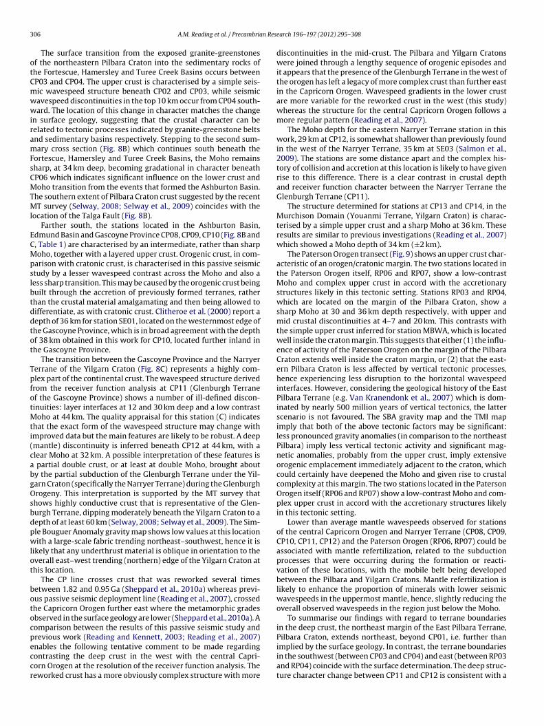
Fig. 8. Summary structure across the Capricorn Orogen. The major features identified from receiver function analysis, and listed in Table 1, are shown with the correct spatialrelationship between adjacent stations and the (surface) boundaries of major geological provinces. Ham–Fort–TC = Hamersley, Fortescue and Turee Creek. No u.c. discon. = noupper crustal (wavespeed) discontinuities.
304 A.M. Reading et al. / Precambrian Research 196– 197 (2012) 295– 308
Table 1A summary of conclusions drawn from the receiver function analysis together with a qualitative appraisal of the confidence in those conclusions. See text for an explanationof letters (which run A–D) and notes on Moho characterisation. Mantle wavespeeds are given in comparison to the continental crust S wavespeed vs depth profile shown inpale blue on the output plots for each station in Figs. 6 and 7 (see Fig. 6 caption).
egion, the Moho is a little deeper, at 34 km, but remains sharp. Athe southern margin of the Fortescue, Hamersley and Turee Creekasins, near the boundary with the Ashburton Basin, station CP06
lso shows the Moho at a depth of 34 km but a gradational changen wavespeed at this location. Across the large interstation distancelong this section to the southern margin of the Ashburton Basin,
MBWA RP03 RP04
0
10
20
30
40
50
depth (km)
av / high av / high
average
(no u.c. discon)
Mohocharacter
sharp intermediate lowgradational
D
N. E. P I L B A R A
Fig. 9. Summary structure across the Paterson Orog
close to the Edmund Basin, CP08 shows a slightly deeper Mohoat 36 km and a less sharp, intermediate, wavespeed contrast. Thethird section (Fig. 8C) begins, offset from the second section, in
the Edmund Basin. Here, at CP09, the Moho is relatively deep at42 km with an intermediate wavespeed contrast. Station CP10, atthe northeast edge of the Gascoyne Province, shows a similar Moho
RP06 RP07
mantle wavespeed low low
MOHO
contrast x 2 vertical exag.
P A T E R S O N
en. Details as in the previous caption (Fig. 8).
n Res
dswc4rcta
(csrta
f((ttnAcstObsc(
otsiCiCC(
4
ifiHPisat
aacrWbttcp
A.M. Reading et al. / Precambria
epth at 38 km and intermediate wavespeed contrast. CP11, at theouthern edge of the Gascoyne Province, shows complex structurehich could be interpreted as a double Moho: low contrast dis-
ontinuities or changes in wavespeed gradient at 30 km deep and4 km deep (see the discussion section). CP12, on the Narryer Ter-ane, shows a high contrast Moho at 29 km deep, and also a lowontrast discontinuity at 44 km, while stations CP13 and CP14 inhe Murchison Domain of the Yilgarn Craton show a sharp Moho at
depth of 36 km.The shorter transect (station codes ‘RP’), beginning at MBWA
Fig. 9), shows a Moho at a depth of 30 km with a sharp wavespeedontrast. Moving along the transect in a westward direction, thistructure extends to RP03. At RP04, the Moho is 36 km deep, andemains sharp. By RP06 and RP07, across the Paterson Orogen, closeo Telfer, the Moho is again deeper, at 41 and 40 km respectively,nd with a low wavespeed contrast.
The character of the upper crust as indicated by the receiverunction analysis for the stations in the northeast Pilbara CratonCP02, MBWA, CP03: Fig. 8A) and the northwest Yilgarn CratonCP12, CP13 and CP14: Fig. 8C) is simple showing no sharp discon-inuities. In the orogens surrounding the two Archaean Cratons,he crust is generally more complex, showing wavespeed disconti-uities at various depths (CP01, RP06 and RP07, Figs. 8A and 9).lthough the general character is clear, the depths of the dis-ontinuities inferred are not robust determinations for thesetations. Across the Fortescue, Hamersley and Turee Creek Basins,he Ashburton Basin and the northern part of the Capricornrogen, upper crustal discontinuities occur at various depthsetween 4 and 8 km (CP04, CP05, CP06, CP08). Across theouthern part of the greater Capricorn Orogen, uppercrust dis-ontinuities at depths of between 10 and 12 km are inferredCP09, CP10, CP11).
Receiver function analysis does not provide strong constraintsn the wavespeed of the upper mantle, however, the followingrends were observed in the wavespeed profiles for the two tran-ects in this work. Higher than average mantle wavespeeds werenferred for stations in, or adjacent to, the northeastern Pilbararaton (CP02, RP03, RP04). Lower than average wavespeeds were
nferred for stations in the central and southern parts of the greaterapricorn Orogen and Narryer Terrane (CP08, CP09, CP10, CP11,P12) and also for stations associated with the Paterson OrogenRP06, RP07).
. Discussion
In the previous section, crustal and uppermost mantle featuresnherent in the CAPRA passive seismic dataset, according to the con-dence appraisal given in Table 1, were identified systematically.ere, we compare the Capricorn and Paterson Orogens to otherroterozoic mobile belts in other locations. We then discuss themplications of the most notable features identified in this passiveeismic study in the light of previous geophysical investigationsnd the current understanding of surface geology summarised inhe introduction (Section 1).
An early compilation of the seismological and geochemical char-cteristics of Precambrian lithosphere was presented by Durrheimnd Mooney (1994). They made the generalisation that Archaeanrust is usually 27–40 km thick whereas Proterozoic crust is in theange 40–55 km with a substantial high velocity layer at its base.
e find that the Archaean Pilbara Craton and Yilgarn Crust crustoth fall into the range expected for Archaean crust and the crustal
hickness values for the Capricorn and Paterson Orogens fall intohe lower range of the thickness values expected for Proterozoicrust. The dominant controls on crustal thickness are the tectonicrocesses behind its formation and evolution. Crustal depth may
earch 196– 197 (2012) 295– 308 305
be indicative of age only in the case where different tectonic pro-cesses dominate during different ages within in a group of terranes.Further generalisation of the thickness and seismic velocity char-acteristics of Proterozoic crust, and in particular, craton–orogenmargins does not reveal any obvious trends. For example, the Pro-terozoic Namaqua-Natal Belt of southern Africa shows a muchhigher seismic wavespeed contrast across the Moho, and a muchsharper Moho, than the crustal structures inferred in this study(Nair et al., 2006; Yang et al., 2008). Also the crustal thicknessesinferred for the Namaqua-Natal Belt covers a much greater range(40 km to >50 km) than the thicknesses that we infer for the Capri-corn Orogen and Paterson Orogen. A further example is providedfor the Canadian Shield (Thompson et al., 2010) which exhibits arange of crustal thicknesses and characters.
We suggest that each craton–orogen margin has an individualset of structures according to the plate convergence geometries,the presence or absence of allochthonous terranes and the tectonic,volcanic and mantle processes that were operating in that regionat the time of formation.
The data recorded at CP01 (Fig. 4) were very noisy, as is commonwith basin (margin) locations in near-coastal locations. Cautiously,given the moderate quality appraisal, we note that the best-fit Swavespeed structures for this station feature a sharp, shallow Moho(Fig. 8A and Table 1), similar to that seen for the Pilbara Cratonstations. This indicates that Archaean crust extends beneath CP01at depth.
The crust above the Moho at CP01 shows two significant discon-tinuities in structure and is consistent with features seen in layered,younger crust, and hence with the Palaeozoic surface geology. Thecrustal structure from the receiver function analysis therefore sug-gests that Archaean crust lies beneath the Palaeozoic surface rocksin this location. This inference is supported by the broadscale pat-terns shown in the Simple Bouguer Anomaly (SBA) gravity map(GSWA, 2001) and also the low-wavelength components of theTotal Magnetic Intensity (TMI) map (GSWA, 2005). In both cases,the potential field character associated with the Archaean crust ofthe Pilbara Craton continues to the coast to the north of the locationof CP01. In contrast, the surface geology changes from Archaean toMesozoic (or later) between CP02 and CP01.
Stations located within the Pilbara or Yilgarn Cratons are char-acterised by receiver functions of simple form, with little or noobvious layering in the upper crust. We suggest that this is a gen-uine rendition of the crustal structure, and that vertical tectonicswithin the Archaean cratons have largely removed the horizontalwavespeed discontinuities that are often associated with continen-tal crust. We recognise the possibility that energy conversion atany extremely sharp Moho discontinuity could be of significantlyhigher amplitude than conversions due to discontinuities in theupper crust. In this case, the simple upper crustal structure inferredfrom the receiver functions from within the craton interiors couldbe an apparent character, albeit a very recognisable one. Stationsin the passive seismic study located over intracontinental basinscharacteristically show a single layer in the upper crust, while sta-tions associated with collisional margins, such as the southern edgeof the Pilbara Craton and the northern edge of the Yilgarn Cratonshow complex (i.e. multiply layered) structures of various kinds.
Stations CP02, CP03 and RP03 with a sharp Moho, at an inferreddepth of 30 km, provide an improved station density in the north-east Pilbara Craton compared with previous work. There may be aslight gradient in crustal thickness to station CP04 (32 km) althoughthis is at the limit of uncertainty in Moho depth (±2 km). The crustalthickness is in agreement with determinations from previous work
for locations in the northern parts of the Fortescue, Hamersley andTuree Creek Basins reviewed by Salmon et al. (2009): station WS09(Reading et al., 2007) and station SF06 (Clitheroe et al., 2000). Bothstudies inferred Moho depths of 32 km.
3 n Res
otCmwwiramFsCMTMl
ECMpslbtddtot
TpfotMti(cabgOsbdpwlot
botocpeccr
06 A.M. Reading et al. / Precambria
The surface transition from the exposed granite-greenstonesf the northeastern Pilbara Craton into the sedimentary rocks ofhe Fortescue, Hamersley and Turee Creek Basins occurs betweenP03 and CP04. The upper crust is characterised by a simple seis-ic wavespeed structure beneath CP02 and CP03, while seismicavespeed discontinuities in the top 10 km occur from CP04 south-ard. The location of this change in character matches the change
n surface geology, suggesting that the crustal character can beelated to tectonic processes indicated by granite-greenstone beltsnd sedimentary basins respectively. Stepping to the second sum-ary cross section (Fig. 8B) which continues south beneath the
ortescue, Hamersley and Turee Creek Basins, the Moho remainsharp, at 34 km deep, becoming gradational in character beneathP06 which indicates significant influence on the lower crust andoho transition from the events that formed the Ashburton Basin.
he southern extent of Pilbara Craton crust suggested by the recentT survey (Selway, 2008; Selway et al., 2009) coincides with the
ocation of the Talga Fault (Fig. 8B).Farther south, the stations located in the Ashburton Basin,
dmund Basin and Gascoyne Province CP08, CP09, CP10 (Fig. 8B and, Table 1) are characterised by an intermediate, rather than sharpoho, together with a layered upper crust. Orogenic crust, in com-
arison with cratonic crust, is characterised in this passive seismictudy by a lesser wavespeed contrast across the Moho and also aess sharp transition. This may be caused by the orogenic crust beinguilt through the accretion of previously formed terranes, ratherhan the crustal material amalgamating and then being allowed toifferentiate, as with cratonic crust. Clitheroe et al. (2000) report aepth of 36 km for station SE01, located on the westernmost edge ofhe Gascoyne Province, which is in broad agreement with the depthf 38 km obtained in this work for CP10, located further inland inhe Gascoyne Province.
The transition between the Gascoyne Province and the Narryererrane of the Yilgarn Craton (Fig. 8C) represents a highly com-lex part of the continental crust. The wavespeed structure derivedrom the receiver function analysis at CP11 (Glenburgh Terranef the Gascoyne Province) shows a number of ill-defined discon-inuities: layer interfaces at 12 and 30 km deep and a low contrast
oho at 44 km. The quality appraisal for this station (C) indicateshat the exact form of the wavespeed structure may change withmproved data but the main features are likely to be robust. A deepmantle) discontinuity is inferred beneath CP12 at 44 km, with alear Moho at 32 km. A possible interpretation of these features is
partial double crust, or at least at double Moho, brought abouty the partial subduction of the Glenburgh Terrane under the Yil-arn Craton (specifically the Narryer Terrane) during the Glenburghrogeny. This interpretation is supported by the MT survey that
hows highly conductive crust that is representative of the Glen-urgh Terrane, dipping moderately beneath the Yilgarn Craton to aepth of at least 60 km (Selway, 2008; Selway et al., 2009). The Sim-le Bouguer Anomaly gravity map shows low values at this locationith a large-scale fabric trending northeast–southwest, hence it is
ikely that any underthrust material is oblique in orientation to theverall east–west trending (northern) edge of the Yilgarn Craton athis location.
The CP line crosses crust that was reworked several timesetween 1.82 and 0.95 Ga (Sheppard et al., 2010a) whereas previ-us passive seismic deployment line (Reading et al., 2007), crossedhe Capricorn Orogen further east where the metamorphic gradesbserved in the surface geology are lower (Sheppard et al., 2010a). Aomparison between the results of this passive seismic study andrevious work (Reading and Kennett, 2003; Reading et al., 2007)
nables the following tentative comment to be made regardingontrasting the deep crust in the west with the central Capri-orn Orogen at the resolution of the receiver function analysis. Theeworked crust has a more obviously complex structure with more
earch 196– 197 (2012) 295– 308
discontinuities in the mid-crust. The Pilbara and Yilgarn Cratonswere joined through a lengthy sequence of orogenic episodes andit appears that the presence of the Glenburgh Terrane in the west ofthe orogen has left a legacy of more complex crust than further eastin the Capricorn Orogen. Wavespeed gradients in the lower crustare more variable for the reworked crust in the west (this study)whereas the structure for the central Capricorn Orogen follows amore regular pattern (Reading et al., 2007).
The Moho depth for the eastern Narryer Terrane station in thiswork, 29 km at CP12, is somewhat shallower than previously foundin the west of the Narryer Terrane, 35 km at SE03 (Salmon et al.,2009). The stations are some distance apart and the complex his-tory of collision and accretion at this location is likely to have givenrise to this difference. There is a clear contrast in crustal depthand receiver function character between the Narryer Terrane theGlenburgh Terrane (CP11).
The structure determined for stations at CP13 and CP14, in theMurchison Domain (Youanmi Terrane, Yilgarn Craton) is charac-terised by a simple upper crust and a sharp Moho at 36 km. Theseresults are similar to previous investigations (Reading et al., 2007)which showed a Moho depth of 34 km (±2 km).
The Paterson Orogen transect (Fig. 9) shows an upper crust char-acteristic of an orogen/cratonic margin. The two stations located inthe Paterson Orogen itself, RP06 and RP07, show a low-contrastMoho and complex upper crust in accord with the accretionarystructures likely in this tectonic setting. Stations RP03 and RP04,which are located on the margin of the Pilbara Craton, show asharp Moho at 30 and 36 km depth respectively, with upper andmid crustal discontinuities at 4–7 and 20 km. This contrasts withthe simple upper crust inferred for station MBWA, which is locatedwell inside the craton margin. This suggests that either (1) the influ-ence of activity of the Paterson Orogen on the margin of the PilbaraCraton extends well inside the craton margin, or (2) that the east-ern Pilbara Craton is less affected by vertical tectonic processes,hence experiencing less disruption to the horizontal wavespeedinterfaces. However, considering the geological history of the EastPilbara Terrane (e.g. Van Kranendonk et al., 2007) which is dom-inated by nearly 500 million years of vertical tectonics, the latterscenario is not favoured. The SBA gravity map and the TMI mapimply that both of the above tectonic factors may be significant:less pronounced gravity anomalies (in comparison to the northeastPilbara) imply less vertical tectonic activity and significant mag-netic anomalies, probably from the upper crust, imply extensiveorogenic emplacement immediately adjacent to the craton, whichcould certainly have deepened the Moho and given rise to crustalcomplexity at this margin. The two stations located in the PatersonOrogen itself (RP06 and RP07) show a low-contrast Moho and com-plex upper crust in accord with the accretionary structures likelyin this tectonic setting.
Lower than average mantle wavespeeds observed for stationsof the central Capricorn Orogen and Narryer Terrane (CP08, CP09,CP10, CP11, CP12) and the Paterson Orogen (RP06, RP07) could beassociated with mantle refertilization, related to the subductionprocesses that were occurring during the formation or reacti-vation of these locations, with the mobile belt being developedbetween the Pilbara and Yilgarn Cratons. Mantle refertilization islikely to enhance the proportion of minerals with lower seismicwavespeeds in the uppermost mantle, hence, slightly reducing theoverall observed wavespeeds in the region just below the Moho.
To summarise our findings with regard to terrane boundariesin the deep crust, the northeast margin of the East Pilbara Terrane,Pilbara Craton, extends northeast, beyond CP01, i.e. further than
implied by the surface geology. In contrast, the terrane boundariesin the southwest (between CP03 and CP04) and east (between RP03and RP04) coincide with the surface determination. The deep struc-ture character change between CP11 and CP12 is consistent with a
n Res
mnstTm
grstbasttsagatt
csrsspgacatlluoo
icftuitbcpGls
5
oagbttcc
A.M. Reading et al. / Precambria
ajor terrane boundary, and matches the surface expression of theorthern margin of the Narryer Terrane. Stations CP13 and CP14how structures consistent with their common terrane associa-ion in the Youanmi Terrane and contrast notably with the Narryererrane to the north, again the lower crustal structure constraintsatch those of the surface geology.The crustal structures observed in this study may be logically
rouped according to their structural features as inferred by theeceiver function analysis (Table 1). CP02, CP03 and MBWA are veryimilar with a ∼30 km deep Moho and a simple crust and may beermed ‘thin craton’ structures. CP01 and RP03 are similar and maye termed ‘craton edge’ structures with a ∼30 km deep Moho and
complex (i.e. multiply layered) mid-crust. CP04, CP05 and RP04how a single significant layer in the mid-crust, CP04 is somewhatransitional in depth, but CP05 and RP06 are similar and all may beermed ‘craton basin’ structures. CP08, CP09, CP10, RP06 and RP08how a deeper, lower or intermediate contrast Moho at 40 km deep,nd layered or complex crustal character. They may be termed ‘oro-en’ structures. CP13 and CP14 are similar with a simple upper crustnd sharp Moho at 36 km and may be termed ‘medium thick cra-on’ in structure. CP06 and CP11 seem to defy classification andheir orogen edge locations are notable in this regard.
The thin craton and medium thick craton structures (as dis-ussed previously) with simple upper crustal characters, imply aignificant history of vertical tectonic processes which has eitheremoved, or prevented any crustal layering from developing duringtages of active tectonics. The complexity seen in the craton-edgetructures could be a relict feature, implying that vertical tectonicrocesses were less active in these locations (although there is nouarantee that these locations were at the edge of the craton atges significantly older than the date of the adjacent orogen). Itould also be related to the formation of the adjacent orogen orssociated basins, or a combination of both. The layering of the cra-on basin structures could have developed in response to the basinoading, or alternatively basin development was favoured in cratonocations that had less vertical tectonic history. The layering in thepper crust in the orogen locations could similarly be related to theverlying basins. It is certain in this case that the presence of therogen was a significant control on basin development.
The variations in Moho character and depth can also be relatedn the same groupings. The sharp Moho characteristic of Archaeanrust in Western Australia is likely to date from the time of crustormation and may in some cases be related to the preservation ofhe crust. This seems most likely if it is associated with low velocitypper mantle immediately beneath. The Moho beneath the orogens
s a lower contrast discontinuity (intermediate contrast beneathhe Capricorn and low contrast beneath the Paterson). The crustaluilding processes associated with orogenesis resulting in a lowerrust with faster seismic wavespeeds than its Archaean counter-art and hence, a lesser contrast between mantle and lower crust.radational and/or double Mohos make sense in terms of tectonic
ocations with unusual tectonic history where underplating or largecale thrusts are relict structures in the crust.
. Conclusions
This work places new constraints on the broad scale architecturef the crust and uppermost mantle associated with the Capricornnd Paterson Orogens, the Pilbara Craton, and the northwest Yil-arn Craton. In particular we find: (1) a complex ‘double Moho’eneath the station in the southern Gascoyne Province, close to
he suture with northern edge of the Yilgarn Craton; (2) a consis-ent pattern of upper crustal wavespeed discontinuities in orogenicrust in contrast to the relatively simple upper crust of the Archaeanratons and (3) a consistent pattern of a deepened Moho and
earch 196– 197 (2012) 295– 308 307
intermediate discontinuity sharpness, or low contrast at the Mohobeneath the orogens in comparison with the shallower, sharp, pro-nounced Moho of the Archaean cratons. The results are consistentwith a tectonic history whereby the orogens accommodated mostof the horizontal deformation while the cratons acted a rigid blocks.
Acknowledgements
We gratefully acknowledge technical and field personnel: SteveSirotjuk, Armando Arcidiaco, Cvetan Sinadinovski and FabriceFontaine. We also thank many communities, landowners and sta-tion managers for access to station sites across the study area. Ourthanks go to Kate Selway and an anonymous reviewer for theirsuggestions which have greatly improved the manuscript.
Appendix A. Supplementary data
Supplementary data associated with this article can be found, inthe online version, at doi:10.1016/j.precamres.2011.07.001.
References
Abdullah, A., 2007. Seismic body wave attenuation tomography beneath the Aus-tralasian region. Ph.D. thesis, Australian National University, Canberra, Australia,p. 163.
Bagas, L., 2004. Proterozoic evolution and tectonic setting of the northwest PatersonOrogen, Western Australia. Precambrian Research 128, 475–496.
Betts, P.G., Giles, D., Lister, G.S., Frick, L.R., 2002. Evolution of the Australian litho-sphere. Australian Journal of Earth Sciences 49, 661–695.
Blake, T.S., Barley, M.E., 1992. Tectonic evolution of the Late Archaean to EarlyProterozoic Mount Bruce Megasequence Set, Western Australia. Tectonics 11,1415–1425.
Cassidy, J.F., 1992. Numerical experiments in broad-band receiver function-analysis.Bulletin of the Seismological Society of America 82, 1453–1474.
Cassidy, K.F., Champion, D.C., Krapez, B., Barley, M.E., Brown, S.J.A., Blewett, R.S.,Groenewald, P.B., Tyler, I.M., 2006a. A revised geological framework for theYilgarn Craton, Western Australia. GSWA Record 2006/8.
Cassidy, K.F., Czarnota, K., Huston, D.L., Maidment, D., McIntyre, A., Neumann, N.,Potter, A., Meixner, A., Bagas, L., 2006b. New data and new concepts for thePaterson Orogen. GSWA Record 2006/3 n4, pp. 8–10.
Cawood, P.A., Korsch, R.J., 2008. Assembling Australia: Proterozoic building of acontinent. Precambrian Research 166, 1–35.
Champion, D.C., Cassidy, K.F., 2001. Granites of the northern Eastern Goldfields:their distribution, age, geochemistry, petrogenesis, relationships with mineral-isation, and implications for tectonic environment, In: Cassidy, K.F., Champion,D.C., McNaughton, N.J., Fletcher, I.R., Whitaker, A.J., Bastrakova, I.A., Budd, A.R.(Eds.), The characterisation and metallogenic significance of Archean granitoidsin the Yilgarn Craton: MERIWA project M281, Report 222, pp. 2.1–2.49.
Clitheroe, G., Gudmundsson, O., Kennett, B.L.N., 2000. The crustal thickness ofAustralia. Journal of Geophysical Research 105, 13697–13713.
Collins, C.D.N., Drummond, B.J., Nicholl, M.G., 2003. Crustal thickness patterns in theAustralian continent. In: Hillis, R.R., Muller, R.D. (Eds.), Evolution and Dynamicsof the Australian Plate. Geological Society of Australia Special Publication 22 andGeological Society of America Special Publication 327, pp. 121–128.
Compston, W., Pidgeon, R.T., 1986. Jack Hills, evidence of more very old detritalzircons in Western Australia. Nature 321, 766–769.
Darbyshire, F.A., 2003. Crustal structure across the Canadian High Arctic region fromteleseismic receiver function analysis. Geophysical Journal International 152,372–391.
Drummond, B., 1988. A review of crust/upper mantle structure in the Precambrianareas of Australia and implications for Precambrian crustal evolution. Precam-brian Research 40–41, 101–116.
Drummond, B., 2000. Crustal signature of Late Archaean tectonic episodes inthe Yilgarn craton, Western Australia: evidence from deep seismic sounding.Tectonophysics 329, 193–221.
Durrheim, R.J., Mooney, W.D., 1994. Evolution of the Precambrian Lithosphere: seis-mological and geochemical constraints. Journal of Geophysical Research 99,15,359–315,374.
Froude, D.O., Ireland, T.R., Kinny, P.D., Williams, I.S., Compston, W., Williams, I.R.,Myers, J.S., 1983. Ion microprobe identification of 4,100–4,200 Myr-old terres-trial zircons. Nature 304, 616–618.
GSWA, 2001. Gravity Anomaly Map of Western Australia. Western Australia Geo-logical Survey.
GSWA, 2005. Magnetic Anomaly Map of Western Australia, 2nd ed. WesternAustralia Geological Survey.
Hackney, R., 2004. Gravity anomalies, crustal structure and isostasy associated withthe Proterozoic Capricorn Orogen, Western Australia. Precambrian Research128, 219–236.
elffrich, G., Stein, S., 1993. Study of the structure of the slab mantle interface usingreflected and converted seismic-waves. Geophysical Journal International 115,14–40.
vanic, T.J., Wingate, M.T.D., Kirkland, C.L., Van Kranendonk, M.J., Wyche, S., 2010.Age and significance of voluminous mafic-ultramafic magmatic events in theMurchison Domain, Yilgarn Craton. Australian Journal of Earth Sciences 57,597–614.
ohnson, S.P., Sheppard, S., Rasmussen, B., Wingate, M.T.D., Kirkland, C.L., Muhling,J.R., Fletcher, I.R., Belousova, E., 2010. The Glenburgh Orogeny as a record ofPaleoproteroic continent–continent collision. GSWA Record 2010/5, 54pp.
ohnson, S.P., Sheppard, S., Wingate, M.T.D., Kirkland, C.L., Belusova, E., 2011. Tem-poral and Hafnium isotopic evolution of the Glenburgh Terrane basement: anexotic crustal fragment in the Capricorn orogen. GSWA Record 2011/XX, XX.
ennett, B.L.N., 2002. The Seismic Wavefield. Interpretation of Seismograms onRegional and Global Scales, vol. II. Cambridge University Press.
ennett, B.L.N., 2003. Seismic structure in the mantle beneath Australia. In: Hillis,R.R., Muller, R.D. (Eds.), Evolution and Dynamics of the Australian Plate. Geolog-ical Society of Australia Special Publication 22 and Geological Society of AmericaSpecial Publication 327, pp. 7–23.
ennett, B.L.N., Abdullah, A., 2011. Seismic wave attenuation beneath the Aus-tralasian region. Australian Journal of Earth Sciences 58, 285–295.
inny, P., 2004. Reconnaissance dating of events recorded in the southern part ofthe Capricorn Orogen. Precambrian Research 128, 279–294.
artin, D.M., Morris, P.A., 2010. Tectonic setting and regional implications of ca2.2 Ga mafic magmatism in the southern Hamersley Province, Western Australia.Australian Journal of Earth Sciences 57, 911–931.
artin, D.M., Nemchin, A.A., Powell, C.M., 1998. A pre-2.2 age for giant hematiteores of the Hamersley Province, Australia. Economic Geology 93, 1084–1090.
artin, D.M., Sircombe, K.N., Thorne, A.M., Cawood, P.A., Nemchin, A.A., 2008.Provenance history of the Bangemall Supergroup and implications for theMesoproterozoic paleogeography of the West Australian Craton. PrecambrianResearch 166, 93–110.
artin, D.M., Thorne, A.M., 2004. Tectonic setting and basin evolution of the Bange-mall Supergroup in the northwestern Capricorn Orogen. Precambrian Research128, 385–409.
eissner, R., 1986. The Continental Crust: A Geophysical Approach. Academic Press,London.
orris, R.C., Horwitz, R.C., 1983. The origin of the iron-formation-rich HamersleyGroup of Western Australia – deposition on a platform. Precambrian Research21, 273–297.
air, S.K., Gao, S.S., Liu, K.H., Silver, P.G., 2006. Southern African crustal evolution andcomposition: constraints from receiver function studies. Journal of GeophysicalResearch 111, 1–17.
cchipinti, S.A., Sheppard, S., Passchier, C., Tyler, I.M., Nelson, D.R., 2004. Palaeopro-terozoic crustal accretion and collision in the southern Capricorn Orogen: theGlenburgh Orogeny. Precambrian Research 128, 237–255.
ayne, J.L., Hand, M., Barovich, K.M., Reid, A., Evans, D.A.D., 2009. Correlations andreconstruction models for the 2500–1500 evolution of the Mawson Continent.In: Reddy, S.M., Mazumder, R., Evans, E.A.D., Collins, A.S. (Eds.), Palaeopro-terozoic Supercontinents and Global Evolution. Geological Society, London, pp.319–355, Special Publication 323.
eading, A.M., 2005. Investigating the deep structure of terranes and terrane bound-aries: insights from earthquake seismic data. Geological Society, London, SpecialPublications 246, pp. 293–303.
eading, A.M., 2006. The seismic structure of Precambrian and early Palaeozoic ter-ranes in the Lambert Glacier region, East Antarctica. Earth and Planetary ScienceLetters 244, 44–57.
eading, A.M., Kennett, B.L.N., 2003. Lithospheric structure of the Pilbara Craton,Capricorn Orogen and northern Yilgarn Craton, Western Australia, from tele-seismic receiver functions. Australian Journal of Earth Sciences 50, 439–445.
eading, A.M., Kennett, B.L.N., Dentith, M.C., 2003. Seismic structure of the YilgarnCraton, Western Australia. Australian Journal of Earth Sciences 50, 427–438.
eading, A.M., Kennett, B.L.N., Goleby, B., 2007. New constraints on the seismic struc-
ture of West Australia: evidence for terrane stabilization prior to the assemblyof an ancient continent? Geology 35, 379–382.
almon, M., Saygin, E., Group, A.W., 2009. AusMoho: a new Moho map of the Aus-tralian Continent. EOS Transactions AGU 90, Fall Meeting Supplement, AbstractS41C-1941.
earch 196– 197 (2012) 295– 308
Sambridge, M., 1999. Geophysical inversion with a neighbourhood algorithm-I.Searching a parameter space. Geophysical Journal International 138, 479–494.
Selway, K., 2008. Magnetotelluric investigation into the electrical structure of theCapricorn Orogen, Western Australia. GSWA Record 2007/16, 39pp.
Selway, K., Sheppard, S., Thorne, A., Johnson, S., Groenewald, P., 2009. Identifyingthe lithospheric structure of a Precambrian orogen using magnetotellurics: theCapricorn Orogen, Western Australia. Precambrian Research 168, 185–196.
Sheppard, S., Johnson, S.P., Wingate, M.T.D., Kirkland, C.L., 2010a. The Paleoprotero-zoic Capricorn Orogeny: intracontinental reworking not continent–continentcollision. GSWA Record 2010/108, 33pp.
Sheppard, S., Johnson, S.P., Wingate, M.T.D., Kirkland, C.L., Pirajno, F., 2010b. Explana-tory notes for the Gascoyne Province. GSWA Record, 336pp.
Sheppard, S., Occhipinti, S.A., Nelson, D.R., 2005. Intracontinental reworking in theCapricorn Orogen, Western Australia: the 1680–1620 Ma Mangaroon Orogeny.Australian Journal of Earth Sciences 52, 443–460.
Sheppard, S., Occhipinti, S.A., Tyler, I.M., 2003. The relationship between tectonismand composition of granitoid magmas, Yarlarweelor Gneiss Complex, WesternAustralia. Lithos 66, 133–154.
Sheppard, S., Occhipinti, S.A., Tyler, I.M., 2004. A 2005–1970 Ma Andean-typebatholith in the southern Gascoyne Complex, Western Australia. PrecambrianResearch 128, 257–277.
Sheppard, S., Rasmussen, B., Muhling, J.R., Farrell, T.R., Fletcher, I.R., 2007.Grenvillian-aged orogenesis in the Palaeoproterozoic Gascoyne Complex, West-ern Australia: 1030–950 Ma reworking of the Proterozoic Capricorn Orogen.Journal of Metamorphic Geology 25, 477–494.
Shibutani, T., Sambridge, M., Kennett, B., 1996. Genetic algorithm inversion forreceiver functions with application to crust and uppermost mantle structurebeneath eastern Australia. Geophysical Research Letters 23, 1829–1832.
Smithies, R., Bagas, L., 1997. High pressure amphibolite–granulite facies meta-morphism in the Paleoproterozoic Rudall Complex, central Western Australia.Precambrian Research 83, 243–265.
Stein, S., Wysession, M., 2003. An Introduction to Seismology, Earthquakes and Earthstructure. Blackwell Publishing Ltd.
Thorne, A.M., Seymour, D.B., 1991. Geology of the Ashburton Basin WesternAustralia. GSWA Bulletin 139, 141pp.
Thorne, A.M., Trendall, A.F., 2001. Geology of the Fortescue Group, Pilbara Craton,Western Australia. GSWA Bulletin 144, 249pp.
Trendall, A.F., Compston, W., Nelson, D.R., R.J. Bennett, V.C., 2004. SHRIMP zirconages constraining the depositional chronology of the Hamersley Group, WesternAustralia. Australian Journal of Earth Sciences 51, 621–644.
Tyler, I.M., Thorne, A.M., 1990. The northern margin of the Capricorn Orogen, West-ern Australia – an example of an early Proterozoic collision zone. Journal ofStructural Geology 12, 685–701.
van der Hilst, R., Kennett, B.L.N., Christie, D., Grant, J., 1994. Project SKIPPY exploresthe mantle and lithosphere beneath Australia. EOS 75, 177–181.
Van Kranendonk, M.J., Ivanic, T.J., Wingate, M.T.D., Kirkland, C.L., 2010. Long lived,autochthonous development of the Murchison Domain, Yilgarn Craton. Earthsystems, change, sustainability, vulnerability. Geological Society of Australia,Australian Earth Sciences Convention, Canberra, 4 July 2010, p. 130.
Van Kranendonk, M.J., Smithies, R.H., Hickman, A.H., Champion, D.C., 2007. Review:secular tectonic evolution of Archean continental crust: interplay between hor-izontal and vertical processes in the formation of the Pilbara Craton, Australia.Terra Nova 19, 1–38.
Wilde, S.A., Valley, J.W., Peck, W.H., Graham, C.M., 2001. Evidence from detrital zir-cons for the existence of continental crust and oceans on the Earth 4.4 Gyr ago.Nature 409, 175–178.
Wingate, M.T.D., 2002. Age and palaeomagnetism of dolerite sills intruded into theBangemall Supergroup on the Edmund 1:250 000 map sheet, Western Australia.GSWA Record 2002/4, 48pp.
Yang, Y., Li, A., Ritzwoller, M.H., 2008. Crustal and uppermost mantle structure
in southern Africa revealed from ambient noise and teleseismic tomography.Geophysical Journal International 174, 235–248.
Zheng, T.Y., Zhao, L., Zhu, R.X., 2008. Insight into the geodynamics of cratonicreactivation from seismic analysis of the crust-mantle boundary. GeophysicalResearch Letters 35, L08303, doi:10.1029/2008GL033439.