SPE31125 The Correct m m Soekt y of Petrolewn Engineers Selection and Application Methods for Adsorption and Precipitation Scale Inhibitors M. M. Jordan SPE, K. for Squeeze Treatments in S. Sorbic SPE, G. M. Graham SPE, K. North Sea Oilfields Taylor,’ K. E. Hourston + SPE and S. Hennesseyt Department of Petroleum Engineering, Heriot-Watt University, Edinburgh, U.K. ● Shell Exploration and Production (Aberdeen) , ‘Total Oil Marine (Aberdeen) and t LASMO North Sea (Aberdeen). COPYIMIIII’M., %CWIYof Petroleum Ergumrs, Inc Tim paper wos prcpwud f.< prt.w.tat!o. .II the SPE Fommuon Damage Control Symp?swm. Ld4ycuc. LA, 14-15 FebruW l% This paper was sclcclcd ioc prcsmla!im hy an SPE program Commmw kdlowmg rcwcw.! mfmmmon Ccmlamed m m abwmcr whmmcd hy the author(s). Contcnl$ or the pap, LUSpn!.wnkd, have nnl hyn Izwewed hy !he SrmcIy 01 PcIro!cum E.gmccrs and arc subpm !0 cormctmn by !hc au!hor(s) TIc m.t.rid, as WCSC.EIJ. dm.s not IECC.WWIY rdkt any p,sitro. .( dw .SOCEIY d Fwr.1..m Engmwrs, IS orfi..rs or m.rn!wm Pa~m prcscnkd at SPE mmungs arc s.hJcm to puhlwalmn r.. icw hy FJImnJl C’lmmlue’x of the Somy .r Pclml.unl Enpncem Prom,.s,on t<,c<,py i%re.mcl.d tom oh-trim of .<>( more lhm 30(1 word. IIluwatm. s may ..1 h copmd. Th. .hstmck should .ontwi con.pt. uou% .cknowlcdgemcm of where md by whom the p.pcr m pn’sem.d w,,,, L,lImnm. SPE, P () 6,). 813836, Rmharrlwn, TX 7S083-3! 716.USA (F,c!im!lc 2149S2 9475) ABSTRACT Over the past three years, [he Oilfield Scale Research Group at Heriot-Wat[ has conducted a number field studies to evalua[ed scale inhibitors for both downhole squeeze application and topside continuous injection for a number of North Sea operating companies. This paper presents an approach for screening commercial sulphate and carbonate scale inhibitors for field application. The screening results, which include data from static/dynamic inhibitor efficiency, static adsorption, compatibility and thermal stability are used to rank the performance of commercial scale inhibitors. From this short list, a small number ( I to 3) candidate products are taken on to reservoir condition coreflooding. In [he screening of topside scale inhibitors, no adsorption tests are conducted. Results from adsorption and precipitation type coreflood will be compared for polymer and phosphonate chemistries selected using these screening procedures. Such coreflood serve botb to evaluate the squeeze lifetime performance and to assess the Ievcls of formation damage caused by the scale inhibitor package. Tbe strategy of deriving a dynamic isotherm which can be utilised in computer modeliing of the coreflood data to produce a “Field Squeeze Slrategy” will be outlined. This systematic approach provides a set of effective and economical me[hods for the chemical screening of scale inhibitors. This results in an improved field application strategy with longer squeeze lifetimes, while rninimising formation damage potential. INTRODUCTION The downhole and topside formation of both sulphate and carbonate inorganic scales can be a serious problem in oilfield production operations. One of the most common and efficient methods for preventing the formation of such deposits is through the use of chemical scale inhibitor “squeeze” treatments. 1“6 Two main types of inhibitor squeeze treatment can be carried out where the intention is either (a) to adsorb the inhibitor on the rock substrate by a physical-chemical process using a phosphonate or a polymeric material; or (b) to extend the squeeze lifetime of poorly adsorbing scale inhibitors by precipitation (or phase separation) which is commonly achieved by adjusting the solution chemistry ([Ca2+], pH, temperature) of a polymeric inhibitor such as poly phosphino carboxylic acid (PPCA). The central factor governing the dynamics of the inhibitor return curve in adsorption/desorption treatments is the inhibitor/rock interaction as described by the adsorption isotherm, r(C). This is a function of the inhibitor type, molecular weight, pH, temperature, mineral substrate and the brine strength and composition.2-s,7 -12 The precise form of r(C) determines the squeeze lifetime, as has been described in detail in a number of previous papers. 13-18The “precipitation squeeze” process is based on the formation of a gel-like calcium salt, usually of poly phospbinocarboxy lic acid scale inhibitor, within the formation. “Precipitation” (or phase separation) is controlled either by temperature and/or pH19-23 although it will generally involve a coupled adsorption process.24 In this paper, our objective is to present a general methodology for the screening of chemical scale inhibitors for both downhole and topside applications. This is illustrated by results generated for application in four North Sea fields, although [be Oilfield Scale Research Group have actually applied these methods to over 20 fields. Use is made of static References and illustrations at end of paper 523
Transcript
SPE31125
The Correct
mm
Soekt y of Petrolewn Engineers
Selection and Application Methods for Adsorption and PrecipitationScale Inhibitors
M. M. Jordan SPE, K.
for Squeeze Treatments in
S. Sorbic SPE, G. M. Graham SPE, K.
North Sea Oilfields
Taylor,’ K. E. Hourston + SPE and S. Hennesseyt
Department of Petroleum Engineering, Heriot-Watt University, Edinburgh, U.K.
● Shell Exploration and Production (Aberdeen) , ‘Total Oil Marine (Aberdeen) and t LASMO North Sea (Aberdeen).
COPYIMIII I’M., %CWIYof Petroleum Ergumrs, Inc
Tim paper wos prcpwud f.< prt.w.tat!o. .II the SPE Fommuon Damage Control Symp?swm. Ld4ycuc.LA, 14-15 FebruW l%
This paper was sclcclcd iocprcsmla!im hy an SPE program Commmw kdlowmg rcwcw.! mfmmmonCcmlamed m m abwmcr whmmcd hy the author(s). Contcnl$ or the pap, LUSpn!.wnkd, have nnl hynIzwewed hy !he SrmcIy 01 PcIro!cum E.gmccrs and arc subpm !0 cormctmn by !hc au!hor(s) TIcm.t.rid, as WCSC.EIJ. dm.s not IECC.WWIY rdkt any p,sitro. .( dw .SOCEIY d Fwr.1..m Engmwrs,IS orfi..rs or m.rn!wm Pa~m prcscnkd at SPE mmungs arc s.hJcm to puhlwalmn r.. icw hy FJImnJlC’lmmlue’xof the Somy .r Pclml.unl Enpncem Prom,.s,on t<,c<,py i%re.mcl.d tom oh-trim of .<>(more lhm 30(1 word. IIluwatm.s may ..1 h copmd. Th. .hstmck should .ontwi con.pt. uou%.cknowlcdgemcm of where md by whom the p.pcr m pn’sem.d w,,,, L,lImnm. SPE, P () 6,).813836, Rmharrlwn, TX 7S083-3! 716.USA (F,c!im!lc 2149S2 9475)
ABSTRACT
Over the past three years, [he Oilfield Scale Research Group atHeriot-Wat[ has conducted a number field studies to evalua[edscale inhibitors for both downhole squeeze application andtopside continuous injection for a number of North Seaoperating companies. This paper presents an approach forscreening commercial sulphate and carbonate scale inhibitorsfor field application. The screening results, which include datafrom static/dynamic inhibitor efficiency, static adsorption,compatibility and thermal stability are used to rank theperformance of commercial scale inhibitors. From this shortlist, a small number ( I to 3) candidate products are taken on toreservoir condition coreflooding. In [he screening of topsidescale inhibitors, no adsorption tests are conducted.
Results from adsorption and precipitation type coreflood willbe compared for polymer and phosphonate chemistriesselected using these screening procedures. Such corefloodserve botb to evaluate the squeeze lifetime performance and toassess the Ievcls of formation damage caused by the scaleinhibitor package. Tbe strategy of deriving a dynamicisotherm which can be utilised in computer modeliing of thecoreflood data to produce a “Field Squeeze Slrategy” will beoutlined. This systematic approach provides a set of effectiveand economical me[hods for the chemical screening of scaleinhibitors. This results in an improved field applicationstrategy with longer squeeze lifetimes, while rninimisingformation damage potential.
INTRODUCTION
The downhole and topside formation of both sulphate andcarbonate inorganic scales can be a serious problem in oilfieldproduction operations. One of the most common and efficientmethods for preventing the formation of such deposits isthrough the use of chemical scale inhibitor “squeeze”treatments. 1“6 Two main types of inhibitor squeeze treatmentcan be carried out where the intention is either (a) to adsorbthe inhibitor on the rock substrate by a physical-chemicalprocess using a phosphonate or a polymeric material; or (b)to extend the squeeze lifetime of poorly adsorbing scaleinhibitors by precipitation (or phase separation) which iscommonly achieved by adjusting the solution chemistry([Ca2+], pH, temperature) of a polymeric inhibitor such aspoly phosphino carboxylic acid (PPCA).
The central factor governing the dynamics of the inhibitorreturn curve in adsorption/desorption treatments is theinhibitor/rock interaction as described by the adsorptionisotherm, r(C). This is a function of the inhibitor type,molecular weight, pH, temperature, mineral substrate and thebrine strength and composition.2-s,7 -12 The precise form ofr(C) determines the squeeze lifetime, as has been described indetail in a number of previous papers. 13-18The “precipitationsqueeze” process is based on the formation of a gel-likecalcium salt, usually of poly phospbinocarboxy lic acid scaleinhibitor, within the formation. “Precipitation” (or phaseseparation) is controlled either by temperature and/or pH19-23although it will generally involve a coupled adsorptionprocess.24
In this paper, our objective is to present a general methodologyfor the screening of chemical scale inhibitors for bothdownhole and topside applications. This is illustrated byresults generated for application in four North Sea fields,although [be Oilfield Scale Research Group have actuallyapplied these methods to over 20 fields. Use is made of static
References and illustrations at end of paper 523
2 SELECTION AND APPLICATION METHODS FOR SCALE INHIBITORS SPE31125
and dynamic inhibitor efficiency tests, compatibility phaseenvelope determination and thermal stability data. Theinformation generated in these tests is then used in conjunctionwith static adsorption tests to select a small number of scaleinhibitors (typically, 1 to 3) for reservoir conditioncoreflooding. Up to this stage, the experiments are relativelyshort and many products and conditions can be examined quitequickly and cheaply. However, given the time and expenseinvolved in carrying out reservoir condition core floods, it isonly practical to carry out a few well-targeted floods oncarefully selected products. The importance of correctselection and final coreflood evaluation is highlighted.26-28We emphasise that reservoir condition core floods must still becarried out in order to obtain the dynamic isotherms to designthe “Field Squeeze Strategy w6,15.17,2S.*6 and also [O assess any
levels of formation damage.27
SCALE PROBLEM EVALUATION
In the development of a new field, a vital first step is toevaluate the expected scale problem and to attempt topredicted the type of scale and its relative severity. It is alsoimportant to determine the likely location where the scalemight form within the production system; i.e. is the locationprincipally down-hole, typical of sulphate scale, or further upthe well and into Ihe topside facilities, more typical ofcarbonate scale. A number of software packages are availableto predict sulphate scale and carbonate scale. The accuracy ofthese packages is principally controlled by the quality of thewater chemistry input data used to carry out the scaleprediction. If from detail software modelling of formationwater and injection water mixtures (or purely formation waterin naturally depleted reservoirs), it is deemed necessary toemploy some type of scale prevention strategy, the stagesbelow outline one systematic evaluation route which we havefound particularly useful in field applications.
A number of different types of scale prevention strategy maybe applied in field production systems and these are brieflyreviewed below:
Downhole Protection Using “Squeeze” Treatments:Downhole squeeze treatments are one of the most commonmethods for tackling both sulpha[e and carbonate oilfieldscales, I-6 This type of treatment protects the near wellbore
region and production system. The scale inhibitor solution isinjected into the formation and displaced out some distance byoverflushing, usually with an injected brine. This type oftreatment may well last months to years depending on anumber of factors, such as the nature of the inhibitor chemical,the severity of the scaling problem, the volumetric waterproduction, reservoir chemistry etc.
Topside/Safety Valves Protection.’ The scaling problemswithin many fields in the North Sea require two stages ofprotection involving (a) downhole scale prevention (describedabove); and (b) topside/safety valve protection, In the upperparts of the production system, it is in many cases possible tocontinuously inject a small quantity of scale inhibitor into theproduced fluid stream, prior to the downhole safety values.This chemical will then prevent the formation (or adhesion) ofscale from the point of injection until the disposal of theproduced water from the platform.
Water Injector Protection and Produced Water Reinfection(PWRZ): Waterflooding is the most common recovery methodin oilfields in the North Sea. Although seawater is mostcommonly injected in the North Sea, produced waterreinfection (PWRI) is becoming increasingly common.However, in onshore facilities, aquifer water or river watermay be injected. It is important during the initial stage ofwater injection, or during PWRI, to prevent the formation ofinsoluble scale which may result in localised well injectivityimpairment. The method of protection [o date has be ratherempirical e.g. 50 ppm to 150 ppm of scale inhibitor is dosedinto the first 500,000 to 1,000,000 bbls of injected water andlater in this paper we will discuss a possible improvedapplication strategy.
EXPERIMENTAL METHODS FOR THEEVALUATION OF SCALE INHBITORS
The selection of scale inhibitors for field applications of thetype discussed above has become more critical because of therapidly rising volumes of water which must be treated as manyNorth Sea fields mature. Clearly, the development of reliabletesting and screening methods for scale inhibitors is veryimportant. Over recent years, the Oilfield Scale ResearchGroup (OSRG) at Herio[-Watt University has developed anumber of methods for screening commercially available scaleinhibitors for downhole/topside and water injectionapplications. These methods allow the inhibitors to beevaluated and ranked into an order of suitability using tests ofthe following type: (a) static and dynamic inhibitor efficiencyassessment; (b) bulk inhibitor adsorption onto disaggregatedcore and mineral separates; (c) inhibitor/brine compatibilityphase envelope measurement; (d) determination of inhibitorchemical stability. Test results from (a) - (d) then allow us tomake up a short list for continuation into: (e) reservoircondition coreflooding. Successful core flooding will thenallow us to derive certain quantities which can be used inmodelling to develop the “Field Squeeze Strategy”, asdiscussed elsewhere.6,1S,17,zsZ6 Detailed descriptions of thevarious types of test are presented in the OSRG LaboratoryProcedures Manual. 29
A brief description will be given of the purpose of, and theprocedures used in, each of the methods mentioned above:
Static Inhibitor Efficiency Tests: In this type of inhibitionefficiency test, formation brine and injection brine are mixedin proportions which give both: (i) the largest mass ofprecipitated scale; and (ii) the highest supersaturation index.These quantities are specified by [he scale prediction codes atdown hole and topside temperatures/pressures. Static typeexperiments are performed to evaluate sulphate scaleinhibition efficiency, typically over test periods of 2 to 24hours. Early time behaviour of the inhibitor in such static testsis more associated with nucleation inhibition, whereas, latertime behaviour is related to crystal growth inhibition.Therefore, this type of lest may be used to probe the variousmechanisms through which the different types of scaleinhibitor operate. 30 Such bottle tests are limited to 95°C andcarbonate scales cannot be evaluated properly using thisapproach, due to the absence of pressure control. There hasbeen much discussion on the practical details of how suchexperimental tests should be performed, and recommendationshave been eiven.31 However. OSRG have found that therecommended methods are not as reliable and reproducible as
524
MM JORDAN, K,,S. SORBIE, G. M. GRAHAM, K. TAYLOR. K.E. HOURSTON AND S. HENNESSEY 3
[hrssc developed more recently,zg~z These tes[s arcsuperficially quite simple, but great care must be taken incarrying thcm out as discussed elsewhere. ‘g~z
Dynamic Inhibitor Efficiency Tests (Dynamic Tube BlockingTests): This type of test is very popular in the industry and canbe conducted with bicarbonate in the system in order [oexamine carbonate scale inhibition, since the test equipmentcan easily be back-pressured. In tube blocking [csts, lhcinhibitor solution has a relatively short residence time withinthe scaling coil, typically from seconds [o a few minutes,depending on the flow rate. Thus, such tests tend topreferentially examine tbc nucleation inhibition mechanismal[hough some me~surc of crystal grow[h retardation may begiven since this relates m the scale deposition within the tube.
It is clear tha[ the some interpretation of [he sta[ic and dynamictube blocking [csts is required in the light of the principalmechanism Ihrough which the scale inhibitor under test isthought to operate. w clearly, a scale inhibitor may bc cboscn
IO “piss ccr[ain tes[s” but that (he mechanism in the test maynot relate [o that which would be appropri~te in {he field.
Static Inhibitor Adsorption: In static inhibitor adsorptiontests, ~hc scale inhibitor solution and crushed reservoir core(from the t’onnation into which [he chemical is to bc squccmd)arc brought to equilibrium under a know set of test conditions.Such measurements arc conduced over a range of pH whichthe scale inhibitor may encounter during injection andproduction. From these tests, which are carried out for eischscale inhibitor, it is possible [o rank the scale inhibitors from“good” 10 “poor” in Ierms of their probable adsorptionperformance in the reservoir. Typically, a “good” adsorptionIcvel, r, at a moderate inhibitor concentration (say, -2500ppm) would bc in the range f_ = 0.5-4 m.g/g (mg of inhibitorpcr g of core). This type of testing has been carried out withinthe OSRG for a number of years and the results clearly showthat inhibitor with “good” Ievcls of adsorption give Iongcrsqueeze Iifc and that inhibitors with poor adsorption yieldshort squeeze lifetimes; the latter group may then bcconsidered as candidates for “prccipi[ation” squecz.clreatnlents.’9-~J
The disaggrcgation or crushing of any rock or mineral sampleresul[s in material of higher surface area and with highersurface energy which is therefore more reactive. As a result,the s[aiic beaker tests often give higher values for adsorption[ban those observed in consolidated sandstones containing[hcsc minerals as authigcnic cements, However, even takinginto account these problems, the important sensifh’ifie.~ to pH,calcium and temperature may be in the correct direction forpredicting and analysing consolidated core floodingexperiments in reservoir core. We have previousdemonstrated that this is the case for penta phosphonatc(DETPMP) and phosphino carboxylic acid (PPCA) adsorptiononto quartz and clays. ~s,~s
Scafe [nhibitor/IJrine Compatibility: Man y format ion andproduced brines are rich in divalent cations such as calcium,magnesium, barium and strontium. Some scale inhibitors havevery good tolerance to these divalent cations and others donot; a compatibility phase diagram can be constructed for mostinhibitor types. ]o The formation of a prccipita(cd scaleinhihitor/divalcnt ion complex is the principle hy which“precipitation” squcczcs operate. However, the premature
formation of such a precipitate during injection or early backproduction can result in near wellbore formation damage.Scale inhibitors are tested for their brine compatibility at 100%SW, 50:50 SW:FW and 20;80 SW:FW over an range ofconcentrations from 20% to 500 ppm inhibitor. In this test,pure adsorption products should not show any incompatibility,Products used in prccipita[ion squeeze type treatments will becxpcctcd to show a window of incompatibility, but its isessential to be able to evaluated and utilised this whereappropriate.
Thermal Stability: Thermal stability evaluation is importantwhere reservoir temperatures are sufficiently high - say,exceeding 130”C. Around this Icmperalure, certain scaleinhibitors show a significant decrease in their apparentinhibition efficiency. Therefore, it is important to assess theextent of efficiency decline so that only thermally stablechemicals arc applied in higher temperature reservoirs.Thermal degradation will also results in short squeeze lifetimeas [he inhibitor molecules may be reduced in molecularweight, due [o either hydrolysis or free radial attack at elevatedtemperature in low pH and high TDS (total dissolved solids)brines. Such lower molecular weight species may then showlower levels of retention within the formation. 1‘~os~
Reservoir Condition CoreJooding: As noted above, all ofthe previous tests are relatively short and inexpensive toperform and many can be carried OUI on a wide range ofcommercially available scale inhibitors - say, up to -20.From these initial screening tests, only a small number ofscale inhibitors (say, i to 3) should be taken forward to coreflooding since this is both time consuming and expensive.The most important factors in carrying out relevant reservoircondition scale inhibitor core flooding arc: (i) to choose a coresample that is, to the best of geological/mineralogicaljudgement, “representative” of the formation zones to betreated; (ii) to restore the sample to the appropriate we[tabilityconditions; (iii ) to cstabl ish the correct reservoir temperatureusing synthetic brine of the appropriate composition and at thecorrect pH. The effluent from the coreflood is monitored forpH, inhibi[or concentration, iron, calcium and other criticalion concentrations. In addition, [he pressure is monitoredthroughout the experiments and the mineralogical compositionof the core is determined both before and after the flood iscarried out. This not only rdlows the inhibitor return profilesto be defined, hut also enables any formation damage [o bcassessed. The main steps in these floods broadly follow thefickl inhibitor treatment stages described below and are asfollows:
(i) Seawater saturation and core characterisation;
(ii) Oil reconditioning by agcing with dead crude oil to restorethe sample m a more “appropriate” we(tability condition;walcrflooding to Sor, followed by spearhead treatment (inmost floods):
(iii) Injection of the main inhibitor slug (containing [racer) atroom temperature, followed hy heating to reservoirtemperature and a shut-in;
(iv) Seawater or formation water postflush or back productiona[ reservoir temperature un[il the inhibitor concentration dropsbelow the minimum inhibitor concentration (MIC) for scaleprevention, for that case; typically, 0.2-2 ppm active content;
525-
4 SELECTION AND APPLICATION METHODS FOR SCALE INHIBITORS SPE31 125
After the tlood cycle, the permeability was measured todetermine if the treatment caused any degradation in reservoirproperties. A full mineralogical analysis was carried out onthe post-flooded core material and this was compared with themineralogical results for untreated core samples.
The use of the reservoir condition core flood results to designan improved “Field Squeeze Strategy” has been described inseveral previous papers. b,15,i72s2b,3s,3bThe core flood effluentis analysed to find the adsorption isotherm, r(C), which isthen used in the field modelling. i31* The derivation of theadsorption isotherm, its significance and its use in modellingfield squeeze treatments has also been discussed in detail inother publications. ‘“,]~-]5!17’26,27
SCALE INHIBITOR EVALUATION STRATEGY
The above test methods may be combined in a number of waysto produce the most appropriate screening stages forcommercial scale inhibitor selection for a given fieldapplication. There are some broad groups of tests that aremore useful depending on the type of application problemwhich is being tackled. For example, a producer welltreatment, a topside application or an injector well treatmentwill each require a slightly different test schedule as shown inthe inhibitor test flow charts in Figures 1 to 3. These arediscussed further below.
Producer Well Treatment: The screening methods requiredfor down bole squeeze treatment are the most involved of thethree evaluations. Static and dynamic inhibitor efficiencyscreening should be carried out with the most efficientchemical being carried onto static adsorption studies. At thisstage, the chemicals with good adsorption characteristics aretested for compatibility with various field brines; see Figure 1.The inhibitors with good efficiency but poor adsorption alsoremain in the test program but are taken onto compatibilitytesting to determine whether it is possible to apply suchproducts in a “precipitation” type squeeze treatment. After thecompatibility tests, a pure adsorption type chemical whichshowed no incompatibility problems may then be takenforward to core flooding. However, if the reservoirtemperature is > 130”C, the final product or products shouldalso be tested for their thermal stability. At this stage, anypotential precipitation products would also bc tested forthermal stability. From the results of these tests, one or twoproducts are selected to be applied in a reservoir conditionedcoreflood. The adsorption isotherm, r(C), would then bederived for the various inhibitor/substrate sys[ems. l~lq
Field scale modelling using the various adsorption isothermswould then be performed and the chemical which gave theoptimum performance would be the preferred product. Notethat the “optimum” product in this sense would be the onewhich gave the best economic performance in terms of theindicators being used by that company; e.g. volume ofproduced water treated, least downtime (deferred oil),guaranteed 6 month squeeze life etc. This computer modellingapproach b.1j17.2s2b would be employed to develop the “FieldSqueeze Strategy” for the first squeeze on a well. After thefirst field squeeze, the inhibitor return data may be used to aidin further extending the squeeze life on the same and otherwells within the field,ci 526
Topside Continuous Injection Treatments: The screen ingmethods required for topside scale inhibitor starts with staticand dynamic inhibitor efficiency testing, Products which havegood inhibition efficiency are further evaluated forcompatibility with produced fluids and other productionchemicals they may encounter in the topside process plant; seeFigure 2. The most efficient and compatible chemicals mustfinally be tested for analytical interference effects, This stageof the testing is unique to topside chemicals. If the downholechemical has been chosen, it is important to select a topsidechemical that will not interfere with its analysis. For example,if a phosphonate was being used for downhole application, itwould not be recommended to select another phosphonate fortopside use. However, a phosphorus containing polymer couldbe used for the topside treatment, if appropriate chemicalseparation stages were employed prior to inhibitor analysis. Iftwo non phosphonate Iabelled polymers were used - one fordownhole and the other for topside - it would not be possibleto separate them chemically. To get round such a case, it ispossible to switch off the topside continual injection pumps afew hours prior to taking a produced water sample to preventcontamination. Clearly, this may present some risks and isprobably not good operating practice,
Water Injection Well Treatments and PWRI: The screeningmethods required for a water injector treatment should startwi[h sta[ic and dynamic inhibitor efficiency in order to assesthe most effective scale inhibitor; see Figure 3. Adsorptiontests should then be carried out to determine which of thechemicals has the lowest level of adsorption. For a waterinjector, the lower the level of inhibitor adsorption, the furtherit will propagate into the near wellbore region. This is exactlythe opposite property required by a good squeeze chemical.Chemicals with good efficiency and poor adsorption couldthen be further tested to evaluate their compatibilityproperties; see Figure 3. Chemicals with poor compatibilitywould not be recommended for application due to the risk of“pseudo-scale” formation in the near wellbore formationresulting in a decline in well injectivity. The present empiricalapproach of 50 ppm to 150 ppm of scale inhibitor within thefirst 500,000101,000,000 bbls could be improved by utilisinga mini-squeeze strategy whereby a small squeeze typetreatment is carried out using a slug of between 2.5% and 10%which would be injected until it filled the initial 30 cm to 50cm of the near well bore. The high concentration of the slugwould result in better propagation of the inhibitor into theformation. The slug would be flushed into the reservoir andthe water injection would continue but the injected waterwould no longer require to chemical treatment. Such atreatment strategy is particularly important for PWRI since, inthese cases, the mixed injection (seawater) and produced brineitself may have some scaling tendency, If this were the case,then dosing with a low level of inhibitor (say 10-100 ppm)would be ineffective since the higher adsorption would retardthe inhifitor front relative to the mixed brine front. Thus, themixing scaling brine front would ‘(out run” the inhibitor andwould start to form scale which may be filtered out and maycause formation damage. This would even be the case if theinjectors were thermally fractured. Thus, for PWRI
application, it is even more important to use a concentratedslug treatment strategy, especially if the inhibitor exhibitsmoderate or high levels of adsorption.
526
M.M. JORDAN, KS. SORBIE, G. M. GRAHAM, K, TAYLOR, K,E. HOURSTON AND S. HENNESSEY 5
Examples of results from different scale inhibitor screeningstudies will be used to illustrate some of the points madeafmve.
EXAMPLES OF SCREENING RESULTS
Compositions of all brines used in this study are summarisedin Table 1.
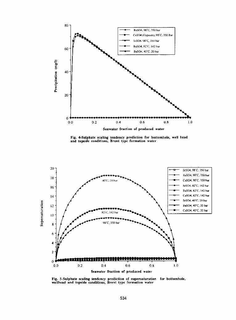
Scaling Tendency and Inhibition Efficiency Screening: InFigures 4 and 5, the scaling tendency in terms ofsupersaturation and mass of precipitate are presented for atypical Brent type formation water. The flowing down holetemperature and pressure was 98-C and 350 bar, at the wellhead safety valves it was 82°C and 140 bar and at the separatoron the platform, it was 40°C, and 20 bar, Using this data, iswas possible to predict the sulphatc scaling tendency for theentire downhole to production system, In terms of [he mass ofscale, only barium sulphate is a problem and it was predictedto be most severe during early seawater breakthrough(maximum precipitation at 10% SW). The mass of scale wasnot significantly affected by the temperature. The maximumsupersaturation was predicted to occur at sf)~. seawater (SW)and 50% formation water (FW) and was significantly affectedby the decline in opera[ing temperature and pressure. Thisinformation immediately indicated that the amount of scaleinhibitor required to control the initial seawater breakthroughwould be relatively small but that, during later stagebreakthrough, more inhibitor would be required: Iikewisc,more inhibitor would also be required as the produced fluidcooled during production. Figures 6 to 8 show the bariumsulphate inhibitor efficiency of a penta phosphonate and ahexa phosphonate scale inhibitor at a 50:50 SW:FW ratio overthe range of temperatures encountered across the operatingsystem. It is clear from these figures that 3 ppm active ofeither inhibitor is sufficient to control scale at 98”C. Morethan 3 ppm of penta phosphonate is required at 82°C but 3ppm of hexa phosphonate is adequate. At 40”C, more than 4ppm of both penta- and hexa phosphonate would be required.If the early seawater break [bough case is examined, it is clearfrom Figure 9 that I ppm of the hexa phosphonate wouldcontrol the scaling problem whereas more than I ppm of thepenta phosphonate would be required. This type of eftlciencyevaluation allows the severity of the scale problcm to beestimated and the appropriate chemical type and concentrationtreatment can be established through the entire productionfacility.
Stalic Inhibitor Adsorption Tests: In Figure 10, the staticadsorption levels onto crushed Tarbert Formation rock of fourgenerically different inhibitors are shown as a function of pH(Inhibitor concentration = 250Q ppm; T = 95”C). It is clearthat the terpolymer and the sulphonated acrylic acid adsorb [oa lesser extent compared with the pen[a phosphonate whichadsorbed less than [he hexa phosphonate. From this data, it ispossible to infer that the penta- and hexa phosphonate shouldbe evaluated in adsorption type coreflood. The terpolymerand sulphonated acrylic copolymer, if they are sufficientlygood in their inhibition performance, may bc evaluated asprecipitation squeeze chemicals by examining theircompatibility and soluhility characteristics. If these same fourchemicals had been evaluated for application in a waterinjector treatment or for PWRI, rather than for a producer welltreatment, then the poorest adsorbing chemical - the
sulphona[ed poly acrylate - would have been the mostappropriated material, hased on the adsorption tests alone,
Inhibitor/Brine Compatibility Testing: The low calciumbrines of the Brent province of the North Sea are not regardedas being problematical in terms of incompatibility between
produced fluid and scale inhibitors; typically, [Ca2+ ] = 300 to900 ppm.~7 In several other fields in the North Sea, formation
brines exist where [Ca2+ ] = 4,000 ppm to 5,500 ppm (in somereservoirs, [he calcium levels are much higher). Such brinescan result in incompatibility and it essential to carry out teststo identify this and to design ways around this problem.Alternately, we may utilise the high divalent levels to designcontrolled precipitation treatments in order to extend the
squeeze lifetime
In this case, no incompatibility of the inhibitor chemicalsshould bc observed at reservoir temperature in a 50:50SW:FW brine, for a simple adsorption squeeze. If such aproblem did exist, it is often possible to design around it by: (i)using a more compatible chemical; (ii) designing a preflush forthe squeeze treatment to push the formation water away fromthe near wellbore and hence prevent mixing of formationwater and the scale inhibitor slug; (iii) adding a chelant [oincrease the divalent ion tolerance of the inhibitor slug alongwith adding a preflush in the squeeze design. These solutionsto the problem have been applied in the North Sea by manyoperators and their supporting service companies.
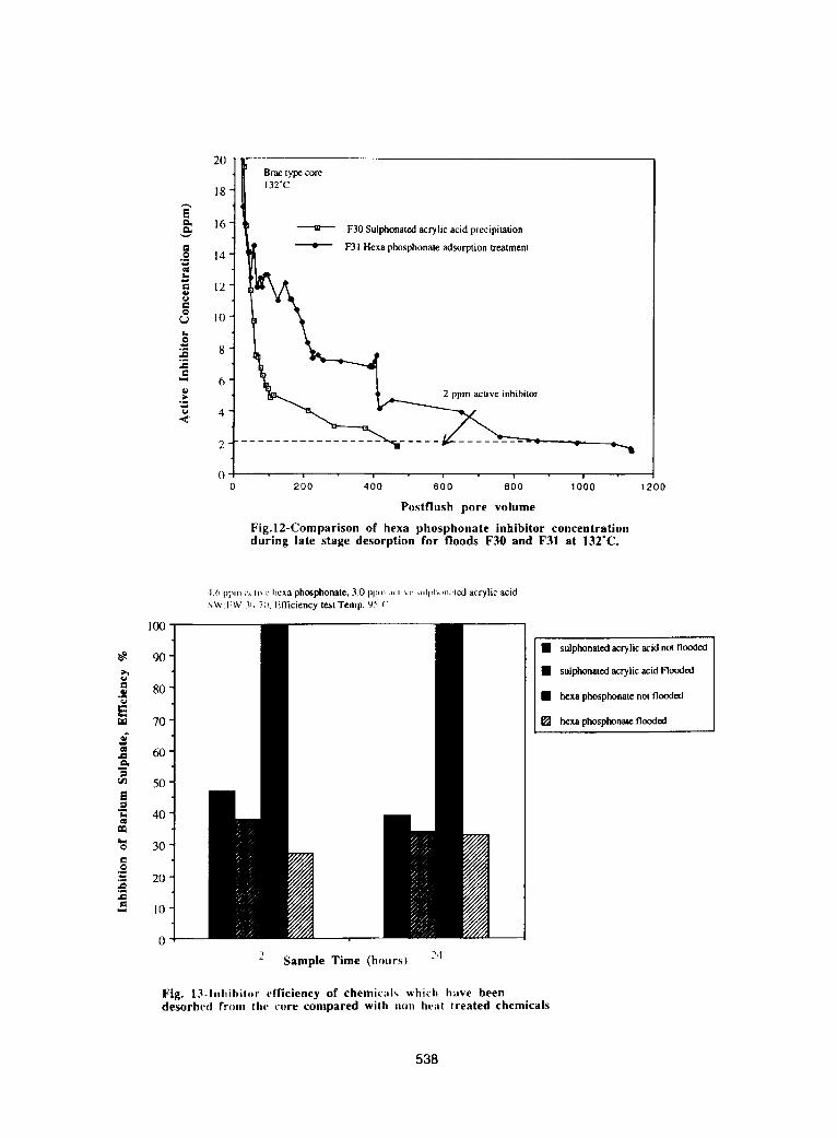
To illustrate the problem of inhibitor incompatibility(precipitation) during either injection or backflow, a floodingexperiment was conducted using Brae Formation reservoircore. The compatibility maps for various inhibitors with a50:50 FW:SW brine (see Table 1) are show in Table 2. Figure1I shows the differential pressure profiles for two inhibitortreatments conducted in identical cores at 132°C. The hexaphosphate used in these test was applied as an adsorption typetreatment and the sulphmrated acrylic acid was applied using aprecipitation type formulation. During the early stages of backflow after a 24 hour shut-in, the polymer precipitation flooddifferential pressure remained constant during the entiretreatment indication no formation damage, However, on backflow from the hexa pbosphonzrte flood, the pressure rapidlyrose and then very slowly declined as the brine flowed throughthe core, The rise and steady decline was due to precipitationof the hexa phosphonate not during shut in but during the earlybackflow then the high calcium formation water (2000 ppmCa) swept through the core resulting in precipitation of a“pseudo scale” (calcium/inhibitor complex). As the inhibitorslowly dissolves the differential pressure fell but this type ofdamage could result in a significant period of reducedproduction initially in a producer well even if the squeeze lifethat resulted was quite appreciable as shown in Figure 12.
If incompatibility occurs across a wide range of seawatermixing ratios and inhibi[or concentrations (e.g. 2070 to 500ppm), then the inhibitor should not bc applied. However, ifthe incompatible region occurs at 20% to 5 Yo, then injectionof the chemical inlo the formation following a preflush willnot result in precipitation during injection of the main slug.The chemical will only precipitate when it has beenoverflushed into the hot region of the reservoir. This type ofstrategy can be carried out safely only if experimental work iscarried out to asses the compatibility of the chemical as a
527
6 SELECTION AND APPLICATION METHODS FOR SCALE INHIBITORS SPE31 125
function of inhibitor concentration at various (FW:SW) brineratios.
Thermal Stability; The need for thermali y stability testing isrecommend at temperatures above 130”C. In Figure 12, thereturned profiles from a hexa phosphonate and sulphonatedacrylic acid flood in Brae Formation core are present duringthe backflow stage of the experiment, Samples of the twoscale inhibitors were collected and their inhibition efficiencieswere compared to original inhibitor samples not flowedthrough the core. In Figure 13, the significant decline in theefficiency of the hexa phosphonate scale inhibi[or is clearlyseen relative to that of the sulphonated acrylic acid. Althoughthe polymer has a lower overall efficiency, it has not beendegraded to the same extent. The need for such thermalstability testing is clear and can now be conducted in hightemperature, pressurised, teflon lined steel bombs.
Results from Dynamic Corejloods: From the staticadsorption and inhibitor efficiency tests, it would appear that ahexa phosphonate in many cases has better inhibitor efficiencyand higher adsorption than a penta phosphonate. The higheradsorption may lead us to suspect that the squeeze lifetime ofthe hexa phosphonate would be much longer than that of thepenta phosphonate. The return profiles of a penta phosphonateand a hexa phosphonate are compared in Figure 14 and there isan apparent inconsistency. This can only be understood whenwe examine the dynamic adsorption isotherms in the lowconcentration region from the reservoir condition core floodsusing these two products. The dynamic adsorption isotherms(derived as explained elsewhere i3]4) for these (WOphosphonate inhibitors are presented for Tarber[ formationcores in Figure I5.
The observed long low-concentration inhibitor return profilefor the hexa-phosphonate is very typical of this type of scaleinhibitor (see Figure 14) and can only be understood byconsidering the shape of the dynamic adsorption isotherms inthe low-concentration steeply-rising region as shown in Figure15. In the threshold concentration region, where C t = 1 -3ppm, the slope of the adsorption isotherm for the hexa-phosphonate is steeper than that of the penta-phosphonate; i.e.
(ari~c)hca > (~rfic)penta. The return velocity of theinhibitor in the threshold region, Va, depends directly on theinverse of this slope as follows:
VQ = Vflui&l[I + ( p/$) @r/~C)Q 1 [1]
This has been explained in several previouspublications 6g10[3J4,15,*5 and all terms are given in theNomenclature. Thus, the direct correlation of return lifetimewith the static adsorption level must be interpreted carefully inthe light of the shape of the dynamic isotherm (which is notevident in such static tests).
In Figure 16, three inhibitor return profiles are presented eachconducted with the same active concentration of inhibitor inthe treatment slug, similar core, postflush brine and at thesame temperature. The two generic scale inhibitors used inthese studies were a penta phosphonate and a phosphinocarboxylic acid. The core material was from the EtiveFormation and the produced fluid was a 50:50 mix SW/FWBrent type water, Flood CI used a penta phosphonateprecipitation formulation, CII used phosphino carboxylic acid
as a precipitation treatment and CIII used the pen[aphosphonate in a conventional adsorption treatment. Theminimum inhibitor concentration (MIC) at downholeconditions (9 I“C, Figure 17) was found to be 0.25 ppm for thePPCA and 1 to 2 ppm for the penta phosphonate. At wellheadconditions (70”C, Figure 18), 0.5 ppm would be required forthe PPCA while 2 ppm would be needed for the pentaphosphonate, When the MIC of the two type of genericinhibitor is taken into account it is possible to evaluate thescale inhibitor properly. PPCA takes 100 pv of postflush toreach its well head MIC and 146 pv 10 reach its downholeMIC. Precipitated penta phosphonate takes 512 pv ofpostflush to reach is wellhead MIC and 526 pv to reach donehole MIC whereas it takes the adsorption treatment takes 573pv to reach well head MIC and 596 pv to reach bottom holeMIC values. It is clear from these results that the pentaphosphonates in adsorption and precipitation returns vastlyextend beyond the PPCA precipitation treatment, evenalthough its MIC is between 4 and 8 time lower than the pentaphosphonate tested at the same conditions.
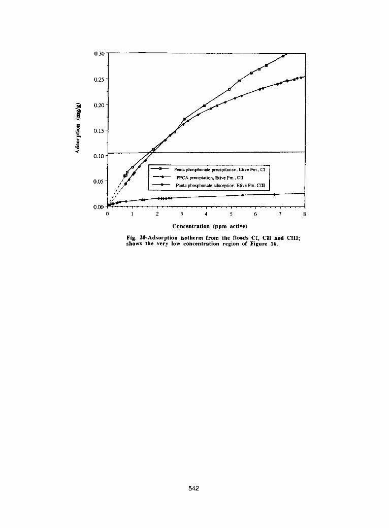
Normally, the precipitation of a generic species would result ina considerable extension in squeeze life. However, we notefrom Figure 16 that there is a cross-over in the curves and thelifetime of the penta phosphonate adsorption is slightly longerthan that of the penta phosphonate precipitation treatment.The reason for this apparent anomaly is due to the volubility ofthe precipitate formed in this test. The precipitate solubdity isfar too high for this very fresh Brent type produced water andthis results in rapid dissolution of the scale inhibitor and thehigher concentration for longer during the early stage of theflood (Figure 16) which removes inhibitor mass making thesqueeze rather shorter than for a simple adsorption. In Figures19 and 20, the isotherm derived from the three flood arepresent and the reason for the flood results described abovecan be clearly explained. Note that, for a precipitationtreatment, we refer to the apparent adsorption and the processis described by a pseudo-isotherm; this is not strictly true asthe model for precipitatiorddissolution process is ratherdifferent. 24 However, it serves our purpose here to makecomparison between the different floods in a more quantitativemanner.
The first point [o note from Figure 19 is that the maximumdyrurnic apparent adsorption level at high inhibitorconcentration is higher for the penta-phosphonate precipitationthan for the penta-phosphonate adsorption; i.e. dynamicrW,,W> ‘pt.”!.nd$ This is due to a considerable amount ofadditional calcium being available witbin the precipitationformulation. Since the penta-phosphonate has a strongeraffinity for calcium, then enhanced adsorption by calciumbridging may be occurring for the adsorption treatment but, ifprecipitation occurs, the amount of apparent adsorption ismuch greater. In the threshold concentration region, where C,= 1 to 2 ppm, tbe slope of the adsorption isotherm for thepenta-phosphonate is slightly steeper that of the penta-phosphonate precipitation treatment; i.e. (~r/=)P,.t. ads >
@f7dC)P-h. Pp, This would explain the slightly longer squeezelife for the penta adsorption treatment (see Equation [1]). Themaximum adsorption for the PPCA is much lower than eventhe penta phosphonate adsorption and the gradient of thePPCA treatment is much less steep than either phosphonatedin the concentration region above 0.5 ppm and only in the very
528
M.M. JORDAN, K..S. SORBIE. G, M. GRAHAM, K. TAYLOR, K.E. HOURSTON AND S. HENNESSEY 7
low concentration region does [he PPCA precipitation profilesteeper particularly in the range O.I to 0.25 ppm.
SUMMARY AND CONCLUSIONS
In this paper, we have considered how it is possible to usestatic and dynamic tests to evaluate scale inhibitorperformance in the field. Inhibition efficiency, staticadsorption, inhibi[or/brine compatibility and thermal stabilitytests have been applied to rank inhibitors for field application.This relatively rapid type of evaluation can assist in theselection of inhibitors for further coreflooding which shouldbe carried out on a minimum number of products (typically, Ito 3). The value of such rapid screening tests is very evidentalthough it is still essential to carry out a much smaller numberof reservoir condition core floods for the shortlisted products.This is necessary if the dynamic adsorption iso[herm, r(C), isto be derived in order to develop the “Field SqueezeStrategy ,,6.1s ,17,25.26 or for the assessment of formation damage
which might occur in the squeeze treatment. ~b Details of thevarious experimental tests are quite lengthy and arcsummarised in the OSRG Laboratory Procedures Manual.’9
The main conclusions arising from this study are as follows:
(i) Scale prediction represents the first step in the cvalwttionprocedure where the nature of the scale and the extent of thescale problem can be estimated from the downholc to thetopside production system.
(ii) Both static and dynamic inhibition efficiency tests provideaccurate and reproducible methods for evaluating various sctdeinhibitors for given problems. However, because diffcrcn[me[hods may probe specific mechanisms of inhibition, somecare must be exercised in interpreting the results of such tests.
(iii) hulk adsorption tests on the disaggregated core materialbroadly give the same .semifivirie.r of inhibitor adsorption (topH, [Caz+], and temperahsre) as those subsequently found inthe core floods. Therefore, adsorption is probably due to thesame rrlechmism in both the mineral separates (reported inprevious papers ‘{) ‘~ 2f2s) and in [he core material. Wheninterpreting bulk adsorption measurements, some cognizancemust he taken of other more subtle factors which do not appearin such tests. The two main ones noted in this work arcillustrated in the comparison between the bulk adsorption andcore flood re[urn behaviour of the penta- und hexa-phosphonatcs, For these products, the MIC values arcdifferent and this affects the mvaning of return lifetime. Also,the shape of the isotherm of the hexa-phosphonate results in aradically different form of the inhihitor return profile in thecore floods. This Iat[er issue can only be studied in dynamiccore floods as cxplhined in the (ext.
(iv) Inhibitor/brine compatibility tests essentially establish thephase diagram of the scale inhibitor and indicate whether thisproblem cm be overcome by redesigning the squcczc (hypreflushing, adding chelants etc. ) or whether the product isunsuitable for application in the reservoir under investigation.
(v) Thermal stability involves testing for the degradation ininhibitor efficiency during coreflood studies or in s[~ticautoclave type hxts. Wc s[rongly recommend carrying outthermal stability tests on the scale inhihitor when the reservoir
(vi) Some limited reservoir condition core flooding isrecommended on the shortlisted screened scale inhibitors forapplications in producer wells. These allow the inhibitoradsorption isotherm to he derived and the initial squeezedesign may then be designed by computer modelling.Coreflooding also allows any formation damage to be assessedprior to application the field.
NOMENCLATURE
c,DETPMP
MIc
PAAPPCAPvspvVa
Vfl,,id
:r(c)
r ma.
r pala
& rhcx,
(arnc)~
inbihitor threshold concentration;inhibi[or - dicthylcnc triamine penta (methylenephosphoric acid);minimum inhibitor concentration for acceptablelevel of scale prevention:inhibitor - poly acrylic acid;inhibitor - poly phosphino carboxylic acid;inhibitor - pdy vinyl sulphonate;pore volumes;velocity of the threshold inhibitor concentrationvalue through the porous medium;velocity of the (luid through the porous medium;rock bulk density;rock porosity;inhibitor dynamic isotherm which depends onconcentration (also Temperature, pH, Caz+ etc..);maximum static inhibitor adsorption level in acrushed core test (mg/g);maximum dynamic inhibitor adsorption levelt’rom core floods for the penta- and hexa-pbosphonatcs (mg/g);slope of the dynamic adsorption isotherm at thethreshold inhibitor concentration level;
(~ r/rdC) ~,xa slope of the (hcxa- and penta-phosphonate)& dynamic adsorption isotherms near the threshold(dr/,3C)wnla inhibitor conccn[ration level;
ACKNOWLEDGEMENTS
The authors would like to thank the following companies forfunding the work of the Heriot-Watt University Oilfield ScaleResearch Group (OSRG): Amcrzrda Hess, Amoco, BakerPerformance Chemicals, BP Exploration, Deminex, Elf,Enterprise Oil, FMC Ltd, Marathon, Nalco/Exxon EnergyChemicals, Norsk Hydro, Shell, Statoil, Texaco, Total OilMarine turd TR Oil Services. Particular thanks arc extended toShell UK, Lasmo North Sea wrd Total Oil Marine for theirpermission to usc field and experimental data in this paper.The support of colleagues in the OSRG is also gratefullyacknowledged.
REFERENCES
1. Vetter, O.J.: “The Chemical Squeeze Process - SomeNcw Information on Some Old Misconceptions”, J.Pet. Tech., pp. 339-353, March 1973.
2. King, G.E. and Warden, S. L.: “Introductory Work inScale Inhihitor Squcczc Performance: Core Test andField Results”, SPE 18485, Presented at the SPEInternational Symposium on Oilfield Chemistry,Hous[on, TX, 8-10 February 1989.
tcmpcrtrturc is (n excess of 130”C.529
8
3.
4,
5.
6.
7.
8.
9.
I0.
11,
12.
SELECTION AND APPLICATION METHODS FOR SCALE INHIBITORS SPE311 25
Pardue, J. E,: “A New Inhibitor for Scale SqueezeApplications”, SPE21023, Presented at the SPEInternational Symposium on Oilfield Chemistry,Anaheim, California, 20-22 February 1991.
Meyers, K. O., Skillman, H.L. and Herring, G. D.:“Control of Formation Damage at Prudhoe Bay,Alaska, by Inhibitor Squeeze Treatment”, J. Pet.Tech., pp. 1019-1034, June 1985.
Przybylinski, J, L.: “Adsorption and DesorptionCharacteristics of Mineral Scale Inhibitors as Relatedto the Design of Squeeze Treatment”, SPE 18486,Presented at the SPE International Symposium onOilfield Chemistry , Hous[on, TX, 8-10 February1989.
Yuan, M. D., Sorbic, K. S.. Todd, A. C., Atkinson, L.M., Riley, H. and Gurden, S.: “The Modelling ofAdsorption and Precipitation Scale Inhibitor SqueezeTreatments in North Sea Fields”, SPE25 165,Presented at the SPE International Symposium onOilfield Chemistry, New Orleans, LA, 3-5 March1993.
Kan, A., Yan, P.B., Oddo, J.E. and Tomson, M. B.:“Sorption and Fate of Phosphonate Scale Inhibitor inthe Sandstone Reservoir: Studied by LaboratoryApparatus With Core Material”, SPE21 714,Presented a[ the SPE Production OperationsSymposium, OK, 7-9 April 1991.
Kan, A.T., Cao, X., Ymr, X., Oddo, J.E. and Tomson,
M.B.: “The Transport of Chemical Scale Inhibitorsand Its Importance to the Squeeze Procedure”, PaperNo. 33 presented at the NACE Annual Conferenceand Corrosion Show, Nashville, TN, 27 April - I May1992.
Sorbic, K. S., Yuan, M.D., Chen, P., Todd, A.C. andWat, R, M. S.: “The Effect of pH on the Adsorptionand Transport of Phosphonate Scale InhibitorThrough Porous Media”, SPE 25165, Presented at theSPE International Symposium on Oilfield Chemistry,Anaheim, CA, 20-22 February 1993
Sorbic, K. S., Jiang, P., Yuan, M. D., Chen, P., Jordan,M. M. and Todd, AC.: “The Effect of pH, Calciumand Temperature on the Adsorption of PhosphonateInhibitor onto Consolidated and Crushed Sandstone”,SPE26605, Presented at the SPE Annual FallConference, Houston, TX, 3-6 October 1993.
Breen, P,J. and Downs, H. H.: “The Use ofAdsorption Thermodynamics in the Development ofScale Inhibitors for High Barium Conten[ OilfieldBrines”, Royal Societyof Chemistry Publication - Chemicals in the Oil/rldl(~fv: Dele/oPn~etz{s and Applications, Edited by
P.H Ogden, 1991.
Graham, G. M. and Sorbic, K. S.: “The Effect ofMolecular Weight on the Adsorption/DesorptionCharacteristics of Polymeric Scale Inhibitors on
13.
14.
15.
16.
17.
18.
19.
20.
21.
22.
23.
NACE Annual Conference, Baltimore, Maryland, 28February -4 March 1994.
Sorbic, KS., Wat, R. M. S. and Todd, A. C.:“Interpretation and Theoretical Modelling of Scale-Inhibitor/Tracer Coreflood”, SPE (ProductionEngineering), pp. 307-312, August 1992.
Sorbic, K.S., Wat, R.M. S,, Todd, A.C and McClosky,T.: “Derivation of Scale Inhibitor Isotherms forSandstone Reservoirs”, Royal Society of ChemistryPublication - Chemicals in the Oil [ndustry:Developments and Applications, Edited by P.HOgden, 1991.
Sorbic, K. S.: “The Improved Design of ScaleInhibitor Squeeze Treatments”, Presented at theWater Management Offshore Conference, Organisedby IBC Ltd., Aberdeen, 22-23 October 1991.
Hong, S,A. and Shuler, P. J.: “A MathematicalModel for the Scale Inhibitor Squeeze Process”,SPEI 6263, Presented at the SPE InternationalSymposium on Oiltleld Chemistry, San Antonio,TX,4-6 February 1987,
Sorhie, K.S., Yuan, M.D. and Todd, A. C.: “TheModelling and Design of Scale Inhibitor SqueezeTreatments in Complex Reservoirs,” SPE21024,Prcscntcd at the SPE International Symposium onOilfield Chemistry, Anaheim, CA., 20-22 February1991.
Yuan, M. D., Sorbic, K. S. and Todd, A. C.: “ANear-Well Simulator for Modelling Scale InhibitorSqueeze Treatments,” Paper N0,24 at the NACEAnnual Conference, Nashville, TN, 27 April-1 May1992,
Carlbcrg, B.L.: “Precipitation Squeeze Can ControlScale in High-Volume Wells” , Oil and Gas Journal,December 1983.
Carlberg, B.L. : “Scale Inhibitor PrecipitationSqueeze for Non-Carbonate Reservoirs”, SPE 17008,Presented at the SPE Production TechnologySymposium, Lubbock, TX, 16-17 November 1987.
Olson, J.B, Moore, D.C and Holland-Jones, N.: “ATemperature Ac[ivated Exlendcd Lifetime ScaleInhibitor Squeeze System”, Paper No. 25 at theNACE Annual Conference, Nashville, TN, April 27-May I I992.
Wat, R. M. S., Montgomery H.T. R., Maclean, A. Fand Bland, I.D.: “Squeeze Application Using aPolymer Scale Inhihitor - A Case History”, Presentedat the 4th International Oilfield ChemicalSymposium, Geilo, Norway, 18-21 April 1993
Rabaioli, R. and Lockhart, T.: “Volubility and PhaseBehaviour of Poiyacrylate Scale Inhibitors and theirImplications for Precipitation Squeeze Treatments”,SPE28998, Prcscntcd at the SPE International
Silica Sand and in Sandstone Cores”, Presented at the ~30
M.M. JORDAN, K..S. SORBIE, G. M. GRAHAM. K. TAYLOR, K.E. HOURSTON AND S. HENNESSEY 9
24.
25.
26.
27.
28.
29.
30.
31.
32.
Symposium on Oilfield Chemistry, San Antonio,TX, 14-17 February 1995.
Malandrino, A., Yuan, M. D., Sorbie,K.S. andJordan, M. M.: “Mechanistic Study and Modelling ofPrecipitation Scale Inhibitor Squeeze Processes”,SPE29001, Presented at the SPE InternationalSymposium on Oilfield Chemistry, San Antonio, TX,14-17 February 1994.
Jordan, M. M., Sorbie,K.S. Jiang,P., Yuan,M.D.,Todd A.C. and Thiery, L.: “The Effect of ClayMinerals, pH, Calcium and Temperature on theAdsorption of Phosphonate Scale Inhibitor onto
Reservoir Core and Mineral Separates”, Presented atNACE Annual Conference, Baltimore, Maryland, 28February -4 March 1994.
Sorbic, K. S., Yuan, M. D, Jordan, M. M. andHourston, K. E.: “Application of a Scale Inhibitor
Squeeze Model to Improve Field Squeeze TreatmentDesign”, SPE28885, Presented at SPEEUROPEC94, London, UK, 25-27 October 1994.
Jordan, M. M., Sorbie,K.S. Jiang,P., Yuan,M.D.,Todd A.C. and HourstonK.E. : “Phosphonate ScaleInhibitor Adsorption/Desorption and the Potential forFormation Damage in Reconditioned Field Core”,SPE27389, Presented at the SPE InternationalSymposium on Formation Damage Control,Lafayette, LA, 9-10 February 1994.
Jordan, M.M, Sorbic, KS, Yuan, M.D , Taylor, K,K. Hourston, K. E. and Rams[ad, K. and Griffin, P.“The Adsorption of Phosphonate and PolymericScale Inhibitors onto Reservoir Mineral Separates”.Presented at the 5th International Oilfield ChemicalsSymposium, Geilo, Norway, 21-23 March 1994.
Graham, G. M., Jordan, M. M., Sorbic, K. S., TheOilfield Scale Research Group LaboratoryProcedures Manual; Version 2.0, Heriot-WattUniversity, September 1995.
Graham, G. M., “A Mechanistic Examination of theFactors Influencing Downhole BaS04 Oilfield ScaleInhibitors and the Design of New Species”, PhDThesis, Department of Petroleum Engineering,Heriot-Watt University, Edinburgh, Scotland, 1994.
Barbour, W., et al. “An Evaluation of the Jar Testfor BaS04 and SrS04 Scale Inhibitors”, paper no. 18,
presen[ed at [he NACE Corrosion92, Nashville,Tennessee, 27 April - I May, 1992.
Makmur, T., “Development of an AppropriateProcedure for Static BaS04 Inhibition EfficiencyTests and Examination of the Sensitivity of VariousInhibitors for Sulphate Scale Inhibition Using theDeveloped Test Methodology”, M.Phil Thesis,Department of Petroleum Engineering, Heriot-WattUniversity, Edinburgh, Scotland, March 1994.
33. Graham, GM. and Sorbic, K,S., “Examination of theChange in Returning Molecular Weight ObtainedDuring Inhibitor Squeeze Treaments UsingPolyacrylate Based Inhibitors”, SPE29000, presentedat the SPE International Symposium on OilfieldChemistry, San Antonio, TX, 14-17 February 1995.
34. Jordan, M. M., Sorbic, K. S., Jiang, P., Yuan, M. D.,Todd, A.C., Taylor, K., Hourston, K.E, and Ramstad,K. “Mineralogical Controls on Inhibitor Adsorption/Desorption in Brent Group Sandstone and TheirImportance in Predicting and Extending FieldSqueeze Lifetimes”, SPE27607, Presented at SPEEuropean Production and Operation Conference,Aberdeen, UK, 15-17 March 1994.
35. Yuan, M. D., Sorbic, K.S., Jiang, P., Chen, P., Jordan,M. M.,Todd, A.C., Hourston, K.E. and Ramstad, K.:“Phosphonate Inhibitor Adsorption on Outcrop andReservoir Rock Substrates: The Static and DynamicAdsorption Isotherms”, Presented at the Fifthinternational Symposium on Chemistry in Jh? od
/rrdusrry, Royal Society of Chemistry, LancasterUniversity, Ambleside, England, 12-15 April 1994.
36. Jordan, M. M., Sorbic, K.S and Hourston, K.H.Practical Application of a Scale Inhibitor SqueezeModel (Squeeze IV) To Improve Field SqueezeTreatments. Proceedings of the MediterraneanPetroleum Conference (MPC 95) 26-29 November1995, Tripoli, Libya.
A brief summary of the sandstones used in this study ispresented below. A fuller account has been publishedeIsewhere.25,27
● Brent Group Sandstone, Tarbert Formation (North Sea):From examination of the cored samples, this sub-arkosicarenite is subrounded to subangular, well sorted andcomprises: 82% quartz, 7- 9~o feldspar, 8- 10% kaolinite, IYomuscovite mica, 1% carbonate and 0.5% lithic fragments. Themain pore filling materials are quartz overgrowths, kaolinite,chlorite and illite.
Etive Formarion, moderate to well sorted sub arkosic arenitesub angular and comprises: 78% quartz, I 1% feldspar, 5%kaolinite + illite, 2% muscovite, 1% carbonate, 2% pyrite.Oseberg Formation poorly to moderately sorted, sub arkosicarenite, angular to sub angular and comprises: 76% quartz, 8?Z0feldspar, 6% muscovite, 2% carbonate and 8% kaolinite +illite.
● Brae Formation: The Brae Formation core used in this workcontains 0.5% muscovite mica, 2-4 % authigenic clay occursin minor amounts (illite 90%, kaolinite 10% of total clay);authigenic carbonates were not evident.
531
TABLE 1 Composition
Synthetic seawaterIon Composition ( m~)
Na+
ca2+Mg2+K+
so42-
cl-sr2+
Ba2+
10,890.4281,368.4602,960.
19,766Z2roZero
of synthetic North Sea brine and Formation water used in this study
Formation water for sealing predictions Formation water (FW)for Floods CI to CIII FW for FloodsF28toF31Ion Comoos ition (mall) Ion Composition (msdl) Ion Composition @.@
9,180214
32225
zero
14,0902448
6,35014525140Z&m
10,4342520
Table 2Test composition 50% Seawater 50% Formation water used in floodsF28toF31chemical type
Solution concentration Test temperature4(YC 5WC Wc 7WC 80”C WC
PPCA 15% N NNNNIO% N NNNNN5% Y Y Y YY
YYY ;Xx;?% YYYX x0.05% Y Y Y x IX
solution concentration Test tesnperatum4(YC 5WC 60”C 7(YC 8WC 9(YC
Sulphonated aeylic acid 15% Y Y YY10% Y Y :YY ;5% YYYYYY
Y Y Y:2% ; Y :Y :Y0.05%Y Y Y Y Y Y
Solution concentration40”C 5rc
Hexa phosphonate 15% Y Y+ Chelant 10% Y Y
5% Y Y1% Y Y0.5% Y Y0.05% Y Y
Test temperatureWC 70”C 80”C 90”CYYYYY
: : :lNNNYNNNYYNN
35,6502,0Q02002,150zero
63,5004501.000
10VC 13tYcNNNNxxxxxxxx
lWC 13(YCYYYYYY
Y;XYY
100-c 130”CYY
Y;NNNNNNN
Y= solution clearN= Solution shows significant evidence of incompatibility i.e. precipitation
Fig. I-Scale inhibitcm screening stages for a producer well
IgOOd
v
good Precipitation type treatment
reservoir < I 3tYC
(’-RL?l. . .
-oir <I 3WC
:-dation
0Droppedfromlest pmgranr
Fig. 2-We inbibircu Screening stages for topside pmteaion
I Iwd
\ JII gwrf
Fig, 3- Scale inhibitor screening srages fors water injector well
poor
good
pxlr
80
60
40
20
0
l— BaSCM,98’C, 350 bar
0.0 0.2 0.4 0.6 0.8 1.0
Seawater fraction of produced water
Fig. 4-Sulphate scaling tendency prediction for bottomhole, well beadand topside conditions, Brent type formation water
.,.
In 1 /--- ‘“”’’oh”
SrSC)4,98”C, 350 bar
BaS04, 91TC,350 bar
CaS04, 9~C. 350 har
SrS04, X2-C, 142 har
BaS04, 82-C, 142 har
CaS04, 82”C, 142 bar
SrSC)4, WC, 20 bar
BaS04, WC, 20 bar
_ CaS04, 41YC, 20 bar
10-
8-
6“
4“
2-
00.0 0.2 0.4 0.6 0.8 1.0
Seawater fraction of produced water
waterFig. 5-Sulphate scaling tendency prediction of supersaturation for bottomhole,wellhead and topside conditions, Brent type form;tion