40
Selection table for single conductors Cables & Wires www.helukabel.com Just click on the products in the selection table. Click on the HELUKABEL logo at the end of the page to go back.

Selection table for single conductors
Cables & Wires
www.helukabel.com
Just click on the products in the selection table.Click on the HELUKABEL logo at the end of the page to go back.

285
K
SINGLE CONDUCTORS
Single Conductors
LiYv -5 to +70 -30 to +80 500 4x X 287
H05V-K -5 to +70 -30 to +80 300/500 4x X X 289
H07V-K / (H)07V-K -5 to +70 -30 to +80 450/750 6x X X 291
H05V-K / (H)07V-K -5 to +70 -30 to +80 300/500 6x X X 293
H05V-U / H07V-U -5 to +70 -30 to +80 300/500 6x X X 294
H07V-R -5 to +70 -30 to +80 450/750 6x X X 295
H05V-K, H07V-K,LiY - barrel opening
296
TOPFLEX® 303 X07V-K-Yö -5 to +80 -40 to +80 0,6/1kV 12x 12x X 297
LifY single core -15 to +80 -15 to +80 300/500 8x 8x X 298
PUR single cores -40 to +80 1kV 10x 5x X X X X 299
H05Z-K / H07Z-K -40 to +90 300/500 6x X X X 300
H05G-U / -K / H07G-U / -R / -K -25 to +110 -40 to +110 300/500 6x X X 302
LiYW / H05V2-K +5 to +90 +5 to -90/105 300/500 4x X 303
H07V2-K +5 to +90 +5 to +90 450/750 10-15x X X 304
HELUTHERM® 145 -35 to +120 -55 to +145 300/500 12,5x 4x X X X X 305
SiF / SiFF -60 to +180 300/500 6x X X 307
SiF/GL, SiD, SiD/GL -60 to +180 300/500 15x 15x X X 308
FZ-LSi +180 +180 6-10kV 7,5x 7,5x X 309
FZ-LS +180 +180 15-20kV 7,5x 7,5x X 309
Neon Light Cables +180 +180 3,5-7,5kV 7,5x 7,5x X X 309
HELUFLON®-FEP-6Y -100 to +205 -100 to +205 600 10x 4x X X X 310
HELUFLON®-PTFE-5Y -190 to +260 -190 to +260 600 10x 4x X X X 311
HELUFLON®-PTFE-5Y -190 to +260 -190 to +260 1000 10x 4x X X X 311
HELUTHERM® 400 -60 to +400 500 15x 15x X X 312
HELUTHERM® 600 / 600-ES -60 to +600 500 15x 15x X /X 313
HELUTHERM® 800 / 800-ES -120 to +750 500 15x 15x X /X 314
HELUTHERM® 1200 / 1200-ES -170 to +1000 500 15x 15x X /X 315
Ground wire ESUY/ESY -5 to +70 -5 to +70 12x 12x 316
GALVANIC CABLE® -40 to + 80 -50 to +80 0,6/1kV 15x 15x X X X 317
H01N2-D / -E -25 to +80 -40 to +80 100/100 12x/10x 12x/10x X X 318
NSGAFÖU 3kV -25 to +80 -40 to +80 1,8/3kV 10x 6x X 319
NSHXAFÖ 3kV -25 to +70 -40 to +90 1,8/3kV 10x 6x X X 320
TOPFLEX® 300 -5 to +80 -40 to +80 0,6/1kV 7,5x 7,5x (X) X 321
KOMPOSPEED® 600 / 600-C -30 to +90 -40 to +100 0,6/1kV 5/7,5x 3/4x X X X X /X 322
The selection table is intended as an initial orientation. Please see the relevant page of the catalogue for detailed information on the product properties.
PageTe
mperatu
re (°C) -
fixed
Nominal v
oltage U 0
/U
Bending radius -
flexing x
Ø
Bending radius -
fixed x Ø
Halogen-free
UV-resis
tant
Outdoor u
se
Drag chain
Colored cores/
VDE 0293
Screened/sh
ielded
HAR/VDE REG no./VDE
UL/CSA
Tem
perature (°
C) - fl
exing
CW&A Edition 27 (published 01.04.2015)
286
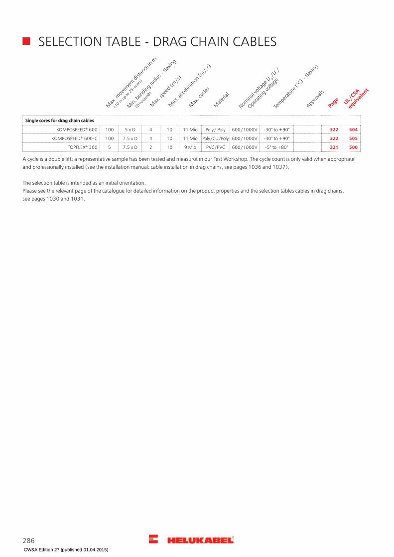
SELECTION TABLE - DRAG CHAIN CABLES
Single cores for drag chain cables
KOMPOSPEED® 600 100 5 x D 4 10 11 Mio Poly/ Poly 600/1000V -30° to +90° 322 504
KOMPOSPEED® 600-C 100 7.5 x D 4 10 11 Mio Poly/CU/Poly 600/1000V -30° to +90° 322 505
TOPFLEX® 300 5 7.5 x D 2 10 9 Mio PVC/PVC 600/1000V -5° to +80° 321 500
A cycle is a double lift: a representative sample has been tested and measurot in our Test Workshop. The cycle count is only valid when appropriatel and professionally installed (see the installation manual: cable installation in drag chains, see pages 1036 and 1037).
The selection table is intended as an initial orientation.Please see the relevant page of the catalogue for detailed information on the product properties and the selection tables cables in drag chains, see pages 1030 and 1031.
Page UL/CSA
equivalent
Min. b
ending radius -
flexing
(
D=outerØ)
Max. s
peed (m/s)
Max. a
cceleratio
n (m/s2 )
Max. c
ycles
Materia
l
Nominal v
oltage U 0
/U /
Operating vo
ltage
Tem
perature (°
C) - fl
exing
Approva
ls
Max. m
ovem
ent dist
ance in
m
(1
0 m up to
25-cores)
CW&A Edition 27 (published 01.04.2015)

LiYv PVC-Single Cores, fine wire stranded, tinned
PropertiesCable structureTechnical dataTinned copper-conductor, toDIN VDE 0295 cl.5, fine-wire,BS 6360 cl.5, IEC 60228 cl.5
PVC single cores adapted toDIN VDE 0812
The materials used in manufacture arecadmium-free and contain no siliconeand free from substances harmful tothe wetting properties of lacquers
Temperature rangeflexing -5°C to +70°Cfixed installation -30°C to +80°C
Core insulation of PVCcompound type YI3 toDIN VDE 0812
TestsPVC self-extinguishing and flame retardantacc. to DIN VDE 0482-332-1-2,DIN EN 60332-1-2, IEC 60332-1 (equivalentDIN VDE 0472 part 804 test method B)
Operating peak voltage0,14 mm² = 500 V0,25-1,5 mm² = 900 V
Core identification see table below
Test voltage0,14 mm² = 1200 V0,25-1,5 mm² = 2500 V
Note
Insulation resistancemin. 10 MOhm x km
For 2-coloured combinations ring marking.
Minimum bending radiusfixed installation 4x core ØRadiation resistanceup to 80x106 cJ/kg (up to 80 Mrad)
ApplicationPVC insulated flexible hook-up wires are used for the connection for low voltage applications, communication apparatus, electronic assemblies andequipment, racks, switchboards etc. correspondingly of VDE 0800 part 1 for the temperature range up to +70°C. Those stranded hook-up wires arenot permitted to install for heavy current application outside of the equipment.
= The product is conformed with the EC Low-Voltage Directive 2006/95/EC.
LiYv2-col.o.col.OGD-BUTRANSGNPKYEVTGYWHRDBNBUGN-YEBKCop.
weightkg / km
Outer Øapprox. mm
Cross-sec.mm²
--20035010-601830151021400570009003300080035015-9005approx. RAL
Spool (standard 100m capacity)Packing
LiYv spool26420264192641826417264162641526414264132641226411264102640926408264072640626405Part no.
1,41,10,1426436264352643426433264322643126430264292642826427264262642526424264232642226421Part no.
2,41,30,2526452264512645026449264482644726446264452644426443264422644126440264392643826437Part no.
4,81,80,526468264672646626465264642646326462264612646026459264582645726456264552645426453Part no.
7,22,00,7526484264832648226481264802647926478264772647626475264742647326472264712647026469Part no.
9,62,1126500264992649826497264962649526494264932649226491264902648926488264872648626485Part no.
14,42,61,5
Continuation
287
Single Conductors
K
CW&A Edition 27 (published 01.04.2015)

LiYv PVC-Single Cores, fine wire stranded, tinnedLiYv
2-col.o.col.OGD-BUTRANSGNPKYEVTGYWHRDBNBUGN-YEBKCop.weightkg / km
Outer Øapprox. mm
Cross-sec.mm²
--20035010-601830151021400570009003300080035015-9005approx. RAL
Barrel (with various capacity)Packing
LiYv barrel26520265192651826517265162651526514265132651226511265102650926508265072650626505Part no.
2,41,30,2526536265352653426533265322653126530265292652826527265262652526524265232652226521Part no.
4,81,80,526552265512655026549265482654726546265452654426543265422654126540265392653826537Part no.
7,22,00,7526568265672656626565265642656326562265612656026559265582655726556265552655426553Part no.
9,62,1126584265832658226581265802657926578265772657626575265742657326572265712657026569Part no.
14,42,61,5
Dimensions and specifications may be changed without prior notice.
288
Single Conductors
Suitable accessories can be found in Chapter X.
• Core end sleeve - ADI
• Core end sleeve - ADU
CW&A Edition 27 (published 01.04.2015)

H05V-K PVC-Single Cores, fine wire stranded
PropertiesCable structureTechnical dataBare Cu-conductor, toDIN VDE 0295 cl.5, fine-wire,BS 6360 cl.5, IEC 60228 cl.5
PVC single cores toDIN VDE 0285-525-2-31 /DIN EN 50525-2-31 and IEC 60227-3
The materials used in manufacture arecadmium-free and contain no siliconeand free from substances harmful tothe wetting properties of lacquersTemperature range
flexing -5°C to +70°Cfixed installation -30°C to +80°C
Core insulation of PVCcompound type TI1 toDIN VDE 0207-363-3 / DIN EN 50363-3and IEC 60227-3
TestsPVC self-extinguishing and flame retardantacc. to DIN VDE 0482-332-1-2,DIN EN 60332-1-2, IEC 60332-1 (equivalentDIN VDE 0472 part 804 test method B)
Nominal voltage U0/U 300/500 VCore identification see table belowTest voltage 2000 V
Insulation resistancemin. 10 MOhm x km
NoteMinimum bending radiusfixed insatallation 4x core Ø The following colours are recommended:
black, white, blue, grey, brown, red,orange, turquoise, violet and pink.Exceptions are the colours green andyellow; these are only permitted if thesafety regulations allows. Green ispermitted for the identification ofluminous decorative chains. All2-coloured combinations of theabovesingle colours are allowed
Radiation resistanceup to 80x106 cJ/kg (up to 80 Mrad)
ApplicationThese single cores are determined for the installation to the inside of apparatus as well as for the protective laying to the lightings, in dry rooms, inproduction facilities, switch and distributor boards, in tubes, under and surface mounting of plasters.
= The product is conformed with the EC Low-Voltage Directive 2006/95/EC.
H05V-KU-BU2-col.o.col.OGD-BUTRANSGNPKYEVTGYWHRDBNBUGN-YEBKCop.
weightkg / km
Outer Ømin. - max.mm
Cross-sec.mm²
5002--20035010-601830151021400570019003300080035015-9005approx. RAL
Coil in cardboard (100m)Packing
H05V-K coil2638629096290952909429093290922909129090290892908829087290862908529084290832908229081Part no.
4,82,1 - 2,50,52638729112291112911029109291082910729106291052910429103291022910129100290992909829097Part no.
7,22,2 - 2,70,752638829128291272912629125291242912329122291212912029119291182911729116291152911429113Part no.
9,62,4 - 2,81
Spool (with various capacity)Packing
H05V-K spool2638926605266042660326602266012660026599265982659726596265952659426593265922659126590Part no.
4,82,1 - 2,50,52639026621266202661926618266172661626615266142661326612266112661026609266082660726606Part no.
7,22,2 - 2,70,752639126637266362663526634266332663226631266302662926628266272662626625266242662326622Part no.
9,62,4 - 2,81
Continuation
289
Single Conductors
K
CW&A Edition 27 (published 01.04.2015)

H05V-K PVC-Single Cores, fine wire strandedH05V-K
U-BU2-col.o.col.OGD-BUTRANSGNPKYEVTGYWHRDBNBUGN-YEBKCop.weightkg / km
Outer Ømin. - max.mm
Cross-sec.mm²
---20035010-601830151021400570019003300080035015-9005approx. RAL
Barrel (with various capacity)Packing
H05V-K barrel2639226655266542665326652266512665026649266482664726646266452664426643266422664126640Part no.
4,82,1 - 2,50,52639326671266702666926668266672666626665266642666326662266612666026659266582665726656Part no.
7,22,2 - 2,70,752639426687266862668526684266832668226681266802667926678266772667626675266742667326672Part no.
9,62,4 - 2,81
Dimensions and specifications may be changed without prior notice. (RK01)
290
Single Conductors
Suitable accessories can be found in Chapter X.
• Core end sleeve - ADI
• Core end sleeve - ADU
CW&A Edition 27 (published 01.04.2015)
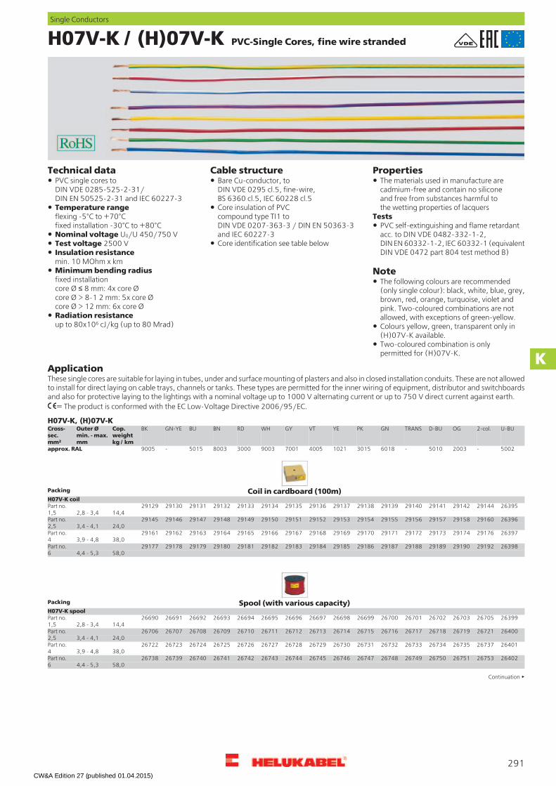
H07V-K / (H)07V-K PVC-Single Cores, fine wire stranded
PropertiesCable structureTechnical dataBare Cu-conductor, toDIN VDE 0295 cl.5, fine-wire,BS 6360 cl.5, IEC 60228 cl.5
PVC single cores toDIN VDE 0285-525-2-31/DIN EN 50525-2-31 and IEC 60227-3
The materials used in manufacture arecadmium-free and contain no siliconeand free from substances harmful tothe wetting properties of lacquersTemperature range
flexing -5°C to +70°Cfixed installation -30°C to +80°C
Core insulation of PVCcompound type TI1 toDIN VDE 0207-363-3 / DIN EN 50363-3and IEC 60227-3
TestsPVC self-extinguishing and flame retardantacc. to DIN VDE 0482-332-1-2,DIN EN 60332-1-2, IEC 60332-1 (equivalentDIN VDE 0472 part 804 test method B)
Nominal voltage U0/U 450/750 VCore identification see table belowTest voltage 2500 V
Insulation resistancemin. 10 MOhm x km
NoteMinimum bending radiusfixed installationcore Ø 8 mm: 4x core Øcore Ø > 8-1 2 mm: 5x core Øcore Ø > 12 mm: 6x core Ø
The following colours are recommended(only single colour): black, white, blue, grey,brown, red, orange, turquoise, violet andpink. Two-coloured combinations are notallowed, with exceptions of green-yellow.Radiation resistance
up to 80x106 cJ/kg (up to 80 Mrad) Colours yellow, green, transparent only in(H)07V-K available.Two-coloured combination is onlypermitted for (H)07V-K.
ApplicationThese single cores are suitable for laying in tubes, under and surface mounting of plasters and also in closed installation conduits. These are not allowedto install for direct laying on cable trays, channels or tanks. These types are permitted for the inner wiring of equipment, distributor and switchboardsand also for protective laying to the lightings with a nominal voltage up to 1000 V alternating current or up to 750 V direct current against earth.
= The product is conformed with the EC Low-Voltage Directive 2006/95/EC.
H07V-K, (H)07V-KU-BU2-col.OGD-BUTRANSGNPKYEVTGYWHRDBNBUGN-YEBKCop.
weightkg / km
Outer Ømin. - max.mm
Cross-sec.mm²
5002-20035010-601830151021400570019003300080035015-9005approx. RAL
Coil in cardboard (100m)Packing
H07V-K coil26395291442914229141291402913929138291372913629135291342913329132291312913029129Part no.
14,42,8 - 3,41,526396291602915829157291562915529154291532915229151291502914929148291472914629145Part no.
24,03,4 - 4,12,526397291762917429173291722917129170291692916829167291662916529164291632916229161Part no.
38,03,9 - 4,8426398291922919029189291882918729186291852918429183291822918129180291792917829177Part no.
58,04,4 - 5,36
Spool (with various capacity)Packing
H07V-K spool26399267052670326702267012670026699266982669726696266952669426693266922669126690Part no.
14,42,8 - 3,41,526400267212671926718267172671626715267142671326712267112671026709267082670726706Part no.
24,03,4 - 4,12,526401267372673526734267332673226731267302672926728267272672626725267242672326722Part no.
38,03,9 - 4,8426402267532675126750267492674826747267462674526744267432674226741267402673926738Part no.
58,04,4 - 5,36
Continuation
291
Single Conductors
K
CW&A Edition 27 (published 01.04.2015)
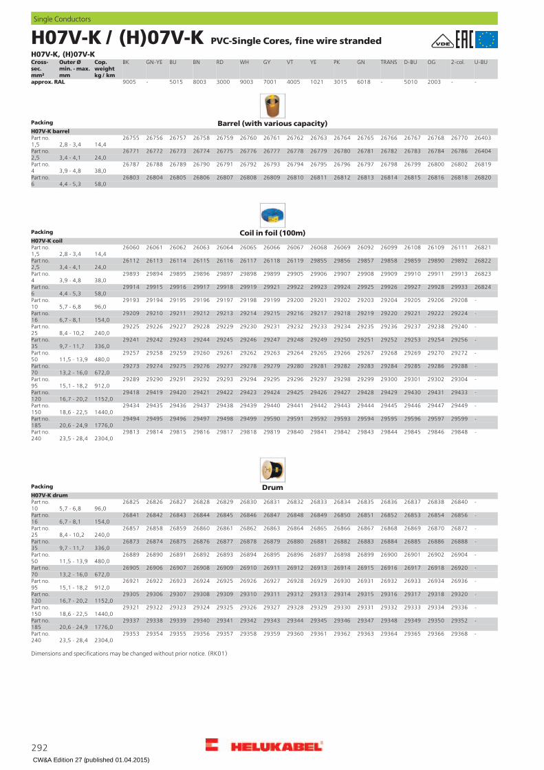
H07V-K / (H)07V-K PVC-Single Cores, fine wire strandedH07V-K, (H)07V-K
U-BU2-col.OGD-BUTRANSGNPKYEVTGYWHRDBNBUGN-YEBKCop.weightkg / km
Outer Ømin. - max.mm
Cross-sec.mm²
--20035010-601830151021400570019003300080035015-9005approx. RAL
Barrel (with various capacity)Packing
H07V-K barrel26403267702676826767267662676526764267632676226761267602675926758267572675626755Part no.
14,42,8 - 3,41,526404267862678426783267822678126780267792677826777267762677526774267732677226771Part no.
24,03,4 - 4,12,526819268022680026799267982679726796267952679426793267922679126790267892678826787Part no.
38,03,9 - 4,8426820268182681626815268142681326812268112681026809268082680726806268052680426803Part no.
58,04,4 - 5,36
Coil in foil (100m)Packing
H07V-K coil26821261112610926108260992609226069260682606726066260652606426063260622606126060Part no.
14,42,8 - 3,41,526822298922989029859298582985729856298552611926118261172611626115261142611326112Part no.
24,03,4 - 4,12,526823299132991129910299092990829907299062990529899298982989729896298952989429893Part no.
38,03,9 - 4,8426824299332992829927299262992529924299232992229921299192991829917299162991529914Part no.
58,04,4 - 5,36-292082920629205292042920329202292012920029199291982919729196291952919429193Part no.
96,05,7 - 6,810-292242922229221292202921929218292172921629215292142921329212292112921029209Part no.
154,06,7 - 8,116-292402923829237292362923529234292332923229231292302922929228292272922629225Part no.
240,08,4 - 10,225-292562925429253292522925129250292492924829247292462924529244292432924229241Part no.
336,09,7 - 11,735-292722927029269292682926729266292652926429263292622926129260292592925829257Part no.
480,011,5 - 13,950-292882928629285292842928329282292812928029279292782927729276292752927429273Part no.
672,013,2 - 16,070-293042930229301293002929929298292972929629295292942929329292292912929029289Part no.
912,015,1 - 18,295-294332943129430294292942829427294262942529424294232942229421294202941929418Part no.
1152,016,7 - 20,2120-294492944729446294452944429443294422944129440294392943829437294362943529434Part no.
1440,018,6 - 22,5150-295992959729596295952959429593295922959129590294992949829497294962949529494Part no.
1776,020,6 - 24,9185-298482984629845298442984329842298412984029819298182981729816298152981429813Part no.
2304,023,5 - 28,4240
DrumPacking
H07V-K drum-268402683826837268362683526834268332683226831268302682926828268272682626825Part no.
96,05,7 - 6,810-268562685426853268522685126850268492684826847268462684526844268432684226841Part no.
154,06,7 - 8,116-268722687026869268682686726866268652686426863268622686126860268592685826857Part no.
240,08,4 - 10,225-268882688626885268842688326882268812688026879268782687726876268752687426873Part no.
336,09,7 - 11,735-269042690226901269002689926898268972689626895268942689326892268912689026889Part no.
480,011,5 - 13,950-269202691826917269162691526914269132691226911269102690926908269072690626905Part no.
672,013,2 - 16,070-269362693426933269322693126930269292692826927269262692526924269232692226921Part no.
912,015,1 - 18,295-293202931829317293162931529314293132931229311293102930929308293072930629305Part no.
1152,016,7 - 20,2120-293362933429333293322933129330293292932829327293262932529324293232932229321Part no.
1440,018,6 - 22,5150-293522935029349293482934729346293452934429343293422934129340293392933829337Part no.
1776,020,6 - 24,9185-293682936629365293642936329362293612936029359293582935729356293552935429353Part no.
2304,023,5 - 28,4240
Dimensions and specifications may be changed without prior notice. (RK01)
292
Single Conductors
CW&A Edition 27 (published 01.04.2015)
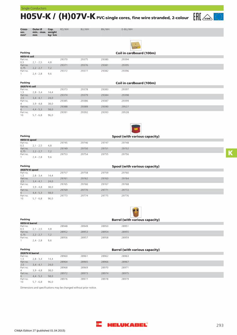
H05V-K / (H)07V-K PVC-single cores, fine wire stranded, 2-colour
D-BU/WHBN/WHBU/WHRD/WHCop.
weightkg / km
Outer Ømin. - max.mm
Cross-sec.mm²
Coil in cardboard (100m)Packing
H05V-K coil29394293802937529370Part no.
4,82,1 - 2,50,529395293812937629371Part no.
7,22,2 - 2,70,7529396293822937729372Part no.
9,62,4 - 2,81
Coil in cardboard (100m)Packing
(H)07V-K coil29397293832937829373Part no.
14,42,8 - 3,41,529398293842937929374Part no.
24,03,4 - 4,12,529399293872938629385Part no.
38,03,9 - 4,8429527293902938929388Part no.
58,04,4 - 5,3629528293932939229391Part no.
96,05,7 - 6,810
Spool (with various capacity)Packing
H05V-K spool29748297472974629745Part no.
4,82,1 - 2,50,529752297512975029749Part no.
7,22,2 - 2,70,7529756297552975429753Part no.
9,62,4 - 2,81
Spool (with various capacity)Packing
(H)07V-K spool29760297592975829757Part no.
14,42,8 - 3,41,529764297632976229761Part no.
24,03,4 - 4,12,529768297672976629765Part no.
38,03,9 - 4,8429772297712977029769Part no.
58,04,4 - 5,3629776297752977429773Part no.
96,05,7 - 6,810
Barrel (with various capacity)Packing
H05V-K barrel28951289502894928948Part no.
4,82,1 - 2,50,528955289542895328952Part no.
7,22,2 - 2,70,7528959289582895728956Part no.
9,62,4 - 2,81
Barrel (with various capacity)Packing
(H)07V-K barrel28963289622896128960Part no.
14,42,8 - 3,41,528967289662896528964Part no.
24,03,4 - 4,12,528971289702896928968Part no.
38,03,9 - 4,8428975289742897328972Part no.
58,04,4 - 5,3628979289782897728976Part no.
96,05,7 - 6,810
Dimensions and specifications may be changed without prior notice.
293
Single Conductors
K
CW&A Edition 27 (published 01.04.2015)
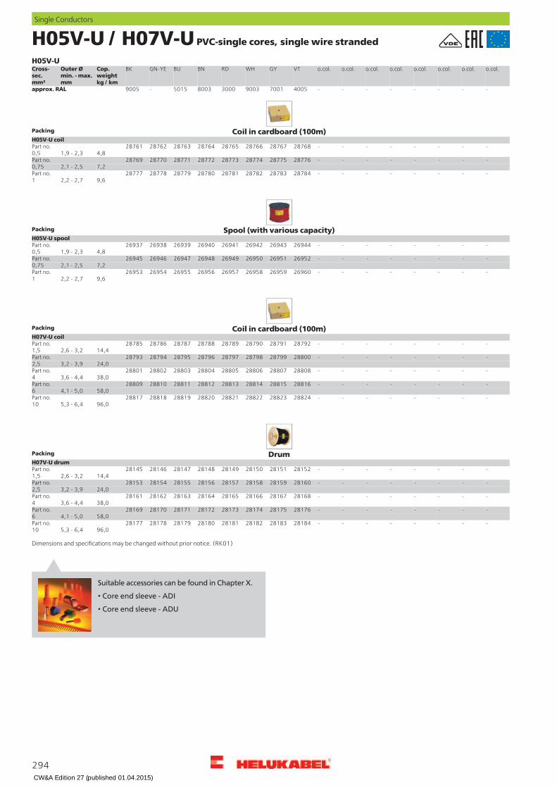
H05V-U / H07V-U PVC-single cores, single wire stranded
H05V-Uo.col.o.col.o.col.o.col.o.col.o.col.o.col.o.col.VTGYWHRDBNBUGN-YEBKCop.
weightkg / km
Outer Ømin. - max.mm
Cross-sec.mm²
--------400570019003300080035015-9005approx. RAL
Coil in cardboard (100m)Packing
H05V-U coil--------2876828767287662876528764287632876228761Part no.
4,81,9 - 2,30,5--------2877628775287742877328772287712877028769Part no.
7,22,1 - 2,50,75--------2878428783287822878128780287792877828777Part no.
9,62,2 - 2,71
Spool (with various capacity)Packing
H05V-U spool--------2694426943269422694126940269392693826937Part no.
4,81,9 - 2,30,5--------2695226951269502694926948269472694626945Part no.
7,22,1 - 2,50,75--------2696026959269582695726956269552695426953Part no.
9,62,2 - 2,71
Coil in cardboard (100m)Packing
H07V-U coil--------2879228791287902878928788287872878628785Part no.
14,42,6 - 3,21,5--------2880028799287982879728796287952879428793Part no.
24,03,2 - 3,92,5--------2880828807288062880528804288032880228801Part no.
38,03,6 - 4,44--------2881628815288142881328812288112881028809Part no.
58,04,1 - 5,06--------2882428823288222882128820288192881828817Part no.
96,05,3 - 6,410
DrumPacking
H07V-U drum--------2815228151281502814928148281472814628145Part no.
14,42,6 - 3,21,5--------2816028159281582815728156281552815428153Part no.
24,03,2 - 3,92,5--------2816828167281662816528164281632816228161Part no.
38,03,6 - 4,44--------2817628175281742817328172281712817028169Part no.
58,04,1 - 5,06--------2818428183281822818128180281792817828177Part no.
96,05,3 - 6,410
Dimensions and specifications may be changed without prior notice. (RK01)
294
Single Conductors
Suitable accessories can be found in Chapter X.
• Core end sleeve - ADI
• Core end sleeve - ADU
CW&A Edition 27 (published 01.04.2015)

H07V-R PVC-single cores, multi wire
H07V-Ro.col.o.col.o.col.o.col.o.col.o.col.o.col.o.col.VTGYWHRDBNBUGN-YEBKCop.
weightkg / km
Outer Ømin. - max.mm
Cross-sec.mm²
--------400570019003300080035015-9005approx. RAL
Coil in foilPacking
H07V-R coil--------2883228831288302882928828288272882628825Part no.
154,06,4 - 7,816-----------2883728836288352883428833Part no.
240,08,1 - 9,725-----------2884228841288402883928838Part no.
336,09,0 - 10,935-----------2884728846288452884428843Part no.
480,010,6 - 12,850-----------2885228851288502884928848Part no.
672,012,1 - 14,670-----------2885728856288552885428853Part no.
912,014,1 - 17,195-----------2886228861288602885928858Part no.
1152,015,6 - 18,8120-----------2886728866288652886428863Part no.
1440,017,3 - 20,9150-----------2887228871288702886928868Part no.
1776,019,3 - 23,3185-----------2887728876288752887428873Part no.
2304,022,0 - 26,6240
DrumPacking
H07V-R drum--------2819228191281902818928188281872818628185Part no.
154,06,4 - 7,816-----------2819728196281952819428193Part no.
240,08,1 - 9,725-----------2820228201282002819928198Part no.
336,09,0 - 10,935-----------2820728206282052820428203Part no.
480,010,6 - 12,850-----------2821228211282102820928208Part no.
672,012,1 - 14,670-----------2821728216282152821428213Part no.
912,014,1 - 17,195-----------2822228221282202821928218Part no.
1152,015,6 - 18,8120-----------2822728226282252822428223Part no.
1440,017,3 - 20,9150-----------2823228231282302822928228Part no.
1776,019,3 - 23,3185-----------2823728236282352823428233Part no.
2304,022,0 - 26,6240
Dimensions and specifications may be changed without prior notice. (RK01)
295
Single Conductors
K
Suitable accessories can be found in Chapter X.
• Core end sleeve - ADI
• Core end sleeve - ADU
CW&A Edition 27 (published 01.04.2015)

296
= The product is conformed with the EC Low-Voltage Directive 2006/95/EC.
Works photo: HELUKABEL®Delivery for one-way barrel
Type one-way cardboard ca. contentscross section 8-on guar in mmm2 dimension in mm
LiY 0,25 500 x 500 x 420 100000,50 500 x 500 x 420 70000,75 500 x 500 x 420 50001,00 500 x 500 x 420 40001,50 500 x 500 x 420 3000
Type one-way barrels ca. contentscross section 8-on guar in mmm2 dimension in mm
H05 V-KH07 V-K 0,50 400 x 400 x 500 40000,75 400 x 400 x 500 35001,00 400 x 400 x 500 30001,50 400 x 400 x 500 20002,50 400 x 400 x 500 12004,00 400 x 400 x 500 9006,00 400 x 400 x 500 800
Type one-way barrels ca. contentscross section 8-on guar in mmm2 dimension in mm
H05 V-KH07 V-K 0,50 400 x 400 x 800 70000,75 400 x 400 x 800 60001,00 400 x 400 x 800 52001,50 400 x 400 x 800 35002,50 400 x 400 x 800 2000
Barrels, one-way barrels or barrels on hire
• The materials used in manufacture are cadmium-free and contain no silicone and free from substances harmful to the wetting properties of lacquers
• PVC self-extinguishing and flame retardant according to DIN VDE 0482-332-1-2, DIN EN 60332-1-2/IEC 60332-1 (equivalent DIN VDE 0472 part 804 test method B)
K = Fine stranded conductor
H05V-K, H07V-K PVC-Single Cores
CW&A Edition 27 (published 01.04.2015)
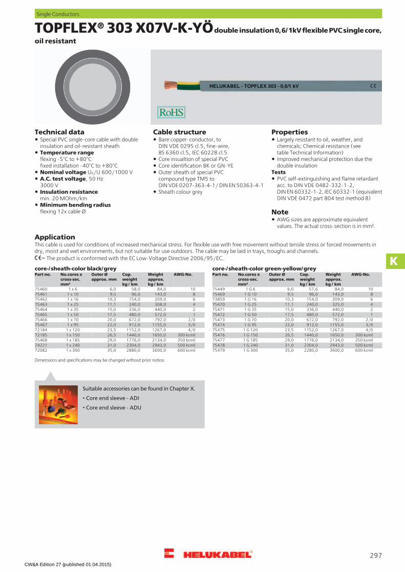
TOPFLEX® 303 X07V-K-YÖdouble insulation 0,6/1kV flexible PVC single core,
oil resistant
PropertiesCable structureTechnical dataBare copper-conductor, toDIN VDE 0295 cl.5, fine-wire,BS 6360 cl.5, IEC 60228 cl.5
Special PVC single-core cable with doubleinsulation and oil-resistant sheath
Largely resistant to oil, weather, andchemicals; Chemical resistance (seetable Technical Information)Temperature range
flexing -5°C to +80°Cfixed installation -40°C to +80°C
Improved mechanical protection due thedouble insulation
Core insualtion of special PVCCore identification BK or GN-YE
TestsNominal voltage U0/U 600/1000 V Outer sheath of special PVCcompound type TM5 toDIN VDE 0207-363-4-1/ DIN EN 50363-4-1
PVC self-extinguishing and flame retardantacc. to DIN VDE 0482-332-1-2,DIN EN 60332-1-2, IEC 60332-1 (equivalentDIN VDE 0472 part 804 test method B)
A.C. test voltage, 50 Hz3000 VInsulation resistancemin. 20 MOhm/km
Sheath colour grey
Minimum bending radiusflexing 12x cable Ø Note
AWG sizes are approximate equivalentvalues. The actual cross-section is in mm².
ApplicationThis cable is used for conditions of increased mechanical stress. For flexible use with free movement without tensile stress or forced movements indry, moist and wet environments, but not suitable for use outdoors. The cable may be laid in trays, troughs and channels.
= The product is conformed with the EC Low-Voltage Directive 2006/95/EC.
core-/sheath-color green-yellow/greycore-/sheath-color black/greyAWG-No.Weight
approx.kg / km
Cop.weightkg / km
Outer Øapprox. mm
No.cores xcross-sec.mm²
Part no. AWG-No.Weightapprox.kg / km
Cop.weightkg / km
Outer Øapprox. mm
No.cores xcross-sec.mm²
Part no.
1084,058,06,01 x 675460 1084,057,66,01 G 6754498143,096,09,51 x 1075461 8143,096,09,51 G 10754696209,0154,010,31 x 1675462 6209,0154,010,31 G 16738594308,0240,011,11 x 2575463 4325,0240,011,11 G 25754702440,0336,015,01 x 3575464 2440,0336,015,01 G 35754711572,0480,017,51 x 5075465 1572,0480,017,51 G 5075472
2/0792,0672,020,01 x 7075466 2/0792,0672,020,01 G 70754733/01155,0912,022,01 x 9575467 3/01155,0912,022,01 G 95754744/01267,01152,023,51 x 12072184 4/01267,01152,023,51 G 12075475
300 kcmil1650,01440,026,51 x 15072185 300 kcmil1650,01440,026,51 G 15075476350 kcmil2134,01776,029,01 x 18575468 350 kcmil2134,01776,029,01 G 18575477500 kcmil2943,02304,031,01 x 24074221 500 kcmil2943,02304,031,01 G 24075478600 kcmil3600,02880,035,01 x 30072082 600 kcmil3600,02280,035,01 G 30075479
Dimensions and specifications may be changed without prior notice.
297
Single Conductors
K
Suitable accessories can be found in Chapter X.
• Core end sleeve - ADI
• Core end sleeve - ADU
CW&A Edition 27 (published 01.04.2015)

LifY Single Core extra fine wires with highest flexibility
PropertiesCable structureTechnical dataBare Cu-conductors, extra fine-wireSpecial plastic stranded wire The materials used in manufacture are
cadmium-free and contain no siliconeand free from substances harmful tothe wetting properties of lacquers
conductor construction see table belowby special design extremly flexibleadapted to DIN VDE 0250,DIN VDE 0285-525-1 / DIN EN 50525-1
Core insulation of PVC (soft, smooth)stranded specially
TestsTemperature rangeflexing -15°C to +80°C PVC self-extinguishing and flame retardant
acc. to DIN VDE 0482-332-1-2,DIN EN 60332-1-2/IEC 60332-1 (equivalentDIN VDE 0472 part 804 test method B)
Operating voltageup to 0,25 mm² 300 V(not for purposes of high current andpower installation)
NoteNominal voltage0,5-1 mm² U0/U 300/500 Vfrom 1,5 mm² U0/U 450/750 V
Please complete the part number forthese cores by adding the suffix forthe colour required as per the list:00 = green, 01 = black, 02 = red,03 = blue, 04 = brown, 05 = white,06 = grey, 07 = violet, 08 = yellow,09 = orange, 10 = transparent,11 = pink, 12 = beige, 13 = 2-colour15= darkblue
Test voltageup to 0,25 mm² = 2 kV0,5-1 mm² = 2,5 kVfrom 1,5 mm² = 3 kVMinimum bending radiusflexing 8x core Ø
AWG sizes are approximate equivalentvalues. The actual cross-section is in mm².
ApplicationThe LifY single cores are used as super flexible insulated strand wires for switch cabinets, as measuring cable for testing, laboratories, research etc.
= The product is conformed with the EC Low-Voltage Directive 2006/95/EC.
AWG-No.Weight
approx.kg / km
Cop.weightkg / km
Outer Øapprox.mm
Cond.make-up(nom. val.)n x wire Ø
Cross-sec.mm²
Corecolour
Part no. AWG-No.Weightapprox.kg / km
Cop.weightkg / km
Outer Øapprox.mm
Cond.make-up(nom. val.)n x wire Ø
Cross-sec.mm²
Corecolour
Part no.
-2,11,21,051 x 0,050,1-151xx 2380,0336,011,74508 x 0,135BK150972380,0336,011,74508 x 0,135GN-YE15139262,61,41,072 x 0,050,14-152xx2380,0336,011,74508 x 0,135BU15127244,22,51,365 x 0,070,25-153xx2380,0336,011,74508 x 0,135BN15128208,05,52,0132 x 0,070,5-154xx2380,0336,011,74508 x 0,135RD151261812,08,02,2195 x 0,070,75-155xx1521,0480,014,76468 x 0,150BK150981718,010,82,5260 x 0,071-156xx1521,0480,014,76468 x 0,150GN-YE151401622,015,03,5192 x 0,11,5-157xx1521,0480,014,76468 x 0,150BU151301437,025,03,8320 x 0,12,5-158xx1521,0480,014,76468 x 0,150BN151311250,040,04,9512 x 0,14-159xx1521,0480,014,76468 x 0,150RD151291071,060,06,0768 x 0,16BK15093
2/0740,0672,015,58967 x 0,170BK150991071,060,06,0768 x 0,16GN-YE151352/0740,0672,015,58967 x 0,170GN-YE151411071,060,06,0768 x 0,16BU151152/0740,0672,015,58967 x 0,170BU151331071,060,06,0768 x 0,16BN151162/0740,0672,015,58967 x 0,170BN151341071,060,06,0768 x 0,16RD151142/0740,0672,015,58967 x 0,170RD151328130,0100,07,31280 x 0,110BK15094
8130,0100,07,31280 x 0,110GN-YE151368130,0100,07,31280 x 0,110BU151188130,0100,07,31280 x 0,110BN151198130,0100,07,31280 x 0,110RD151176187,0160,08,82048 x 0,116BK150956187,0160,08,82048 x 0,116GN-YE151376187,0160,08,82048 x 0,116BU151216187,0160,08,82048 x 0,116BN151226187,0160,08,82048 x 0,116RD151204294,0240,010,53234 x 0,125BK150964294,0240,010,53234 x 0,125GN-YE151384294,0240,010,53234 x 0,125BU151244294,0240,010,53234 x 0,125BN151254294,0240,010,53234 x 0,125RD15123
Dimensions and specifications may be changed without prior notice. (RK01)
298
Single Conductors
CW&A Edition 27 (published 01.04.2015)

PUR Single Core cold resistant, halogen-free
PropertiesCable structureTechnical dataBare copper-conductor, toDIN VDE 0295 cl.5, fine-wire,BS 6360 cl.5, IEC 60228 cl.5
PUR-single cores, halogen-free Halogen-freeFlexible at low temperatures up to -40°CTemperature range
-40°C to +80°C(up to +100°C for short time)
Resistant against pressureCore insulation of special PUR Overroll steadyCore identification see table belowOperating voltage 1000 V Cut and scratchproof
Test voltage3500 V, 15 min.
Resistant toOil
Minimum bending radiusoccasionally moved 10x core Øfixed installation 5x core Ø
See and waste waterAcidsLye
Radiation resistanceup to 100x106 cJ/kg (up to 100 Mrad)
UV-radiation
ApplicationPUR-single cores are suited for installation in switch cabinets, cable assemblies and electronic equipment. Inductive loops in the road surface forcontrolling of light signalling equipment.
= The product is conformed with the EC Low-Voltage Directive 2006/95/EC.
2-col.-
BEIGE1001
OG2003
D-BU5010
TRANS-
PK3015
YE1021
VT4005
GY7000
WH1013
RD3000
BN8003
BU5015
GN-YE-
BK9005
Cop.weightkg / km
Outer Øapprox. mm
Cross-sec.mm²approx. RAL
506645066350659506625066050661506585065750656506555065450653506525065050651Part no.---------------4,82,20,5506795067850674506775067550676506735067250671506705066950668506675066550666Part no.---------------7,22,40,75506945069350689506925069050691506885068750686506855068450683506825068050681Part no.---------------9,62,51507095070850704507075070550706507035070250701507005069950698506975069550696Part no.---------------14,43,01,5507245072350719507225072050721507185071750716507155071450713507125071050711Part no.---------------24,03,72,5507395073850734507375073550736507335073250731507305072950728507275072550726Part no.---------------38,04,34507545075350749507525075050751507485074750746507455074450743507425074050741Part no.---------------58,05,16507695076850764507675076550766507635076250761507605075950758507575075550756Part no.---------------96,06,810507845078350779507825078050781507785077750776507755077450773507725077050771Part no.---------------154,07,816507995079850794507975079550796507935079250791507905078950788507875078550786Part no.---------------240,010,025508145081350809508125081050811508085080750806508055080450803508025080050801Part no.---------------336,011,435508295082850824508275082550826508235082250821508205081950818508175081550816Part no.---------------480,013,250508445084350839508425084050841508385083750836508355083450833508325083050831Part no.---------------672,015,470508595085850854508575085550856508535085250851508505084950848508475084550846Part no.---------------912,017,795508745087350869508725087050871508685086750866508655086450863508625086050861Part no.---------------1152,019,2120508895088850884508875088550886508835088250881508805087950878508775087550876Part no.---------------1440,022,0150
Dimensions and specifications may be changed without prior notice. (RK01)
299
Single Conductors
K
Suitable accessories can be found in Chapter X.
• Core end sleeve - ADI
• Core end sleeve - ADU
CW&A Edition 27 (published 01.04.2015)
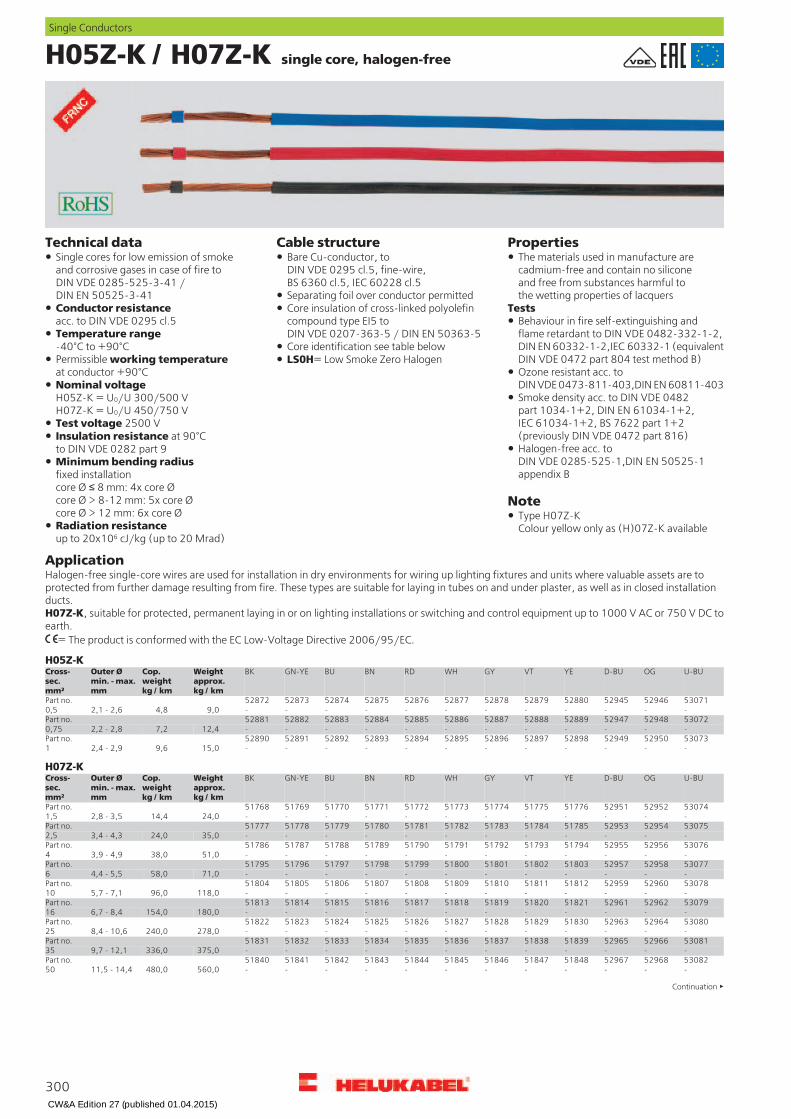
H05Z-K / H07Z-K single core, halogen-free
PropertiesCable structureTechnical dataBare Cu-conductor, toDIN VDE 0295 cl.5, fine-wire,BS 6360 cl.5, IEC 60228 cl.5
Single cores for low emission of smokeand corrosive gases in case of fire toDIN VDE 0285-525-3-41 /DIN EN 50525-3-41
The materials used in manufacture arecadmium-free and contain no siliconeand free from substances harmful tothe wetting properties of lacquersSeparating foil over conductor permitted
TestsConductor resistanceacc. to DIN VDE 0295 cl.5
Core insulation of cross-linked polyolefincompound type EI5 toDIN VDE 0207-363-5 / DIN EN 50363-5
Behaviour in fire self-extinguishing andflame retardant to DIN VDE 0482-332-1-2,DIN EN 60332-1-2,IEC 60332-1 (equivalentDIN VDE 0472 part 804 test method B)
Temperature range-40°C to +90°C Core identification see table belowPermissible working temperatureat conductor +90°C
LS0H= Low Smoke Zero HalogenOzone resistant acc. toDIN VDE 0473-811-403,DIN EN 60811-403Nominal voltage
H05Z-K = U0/U 300/500 VH07Z-K = U0/U 450/750 V
Smoke density acc. to DIN VDE 0482part 1034-1+2, DIN EN 61034-1+2,IEC 61034-1+2, BS 7622 part 1+2(previously DIN VDE 0472 part 816)
Test voltage 2500 VInsulation resistance at 90°Cto DIN VDE 0282 part 9 Halogen-free acc. to
DIN VDE 0285-525-1,DIN EN 50525-1appendix B
Minimum bending radiusfixed installationcore Ø 8 mm: 4x core Øcore Ø > 8-12 mm: 5x core Øcore Ø > 12 mm: 6x core Ø
Note
Type H07Z-KColour yellow only as (H)07Z-K availableRadiation resistance
up to 20x106 cJ/kg (up to 20 Mrad)
ApplicationHalogen-free single-core wires are used for installation in dry environments for wiring up lighting fixtures and units where valuable assets are toprotected from further damage resulting from fire. These types are suitable for laying in tubes on and under plaster, as well as in closed installationducts.H07Z-K, suitable for protected, permanent laying in or on lighting installations or switching and control equipment up to 1000 V AC or 750 V DC toearth.
= The product is conformed with the EC Low-Voltage Directive 2006/95/EC.
H05Z-KU-BUOGD-BUYEVTGYWHRDBNBUGN-YEBKWeight
approx.kg / km
Cop.weightkg / km
Outer Ømin. - max.mm
Cross-sec.mm²
530715294652945528805287952878528775287652875528745287352872Part no.------------9,04,82,1 - 2,60,5530725294852947528895288852887528865288552884528835288252881Part no.------------12,47,22,2 - 2,80,75530735295052949528985289752896528955289452893528925289152890Part no.------------15,09,62,4 - 2,91
H07Z-KU-BUOGD-BUYEVTGYWHRDBNBUGN-YEBKWeight
approx.kg / km
Cop.weightkg / km
Outer Ømin. - max.mm
Cross-sec.mm²
530745295252951517765177551774517735177251771517705176951768Part no.------------24,014,42,8 - 3,51,5530755295452953517855178451783517825178151780517795177851777Part no.------------35,024,03,4 - 4,32,5530765295652955517945179351792517915179051789517885178751786Part no.------------51,038,03,9 - 4,94530775295852957518035180251801518005179951798517975179651795Part no.------------71,058,04,4 - 5,56530785296052959518125181151810518095180851807518065180551804Part no.------------118,096,05,7 - 7,110530795296252961518215182051819518185181751816518155181451813Part no.------------180,0154,06,7 - 8,416530805296452963518305182951828518275182651825518245182351822Part no.------------278,0240,08,4 - 10,625530815296652965518395183851837518365183551834518335183251831Part no.------------375,0336,09,7 - 12,135530825296852967518485184751846518455184451843518425184151840Part no.------------560,0480,011,5 - 14,450
Continuation
300
Single Conductors
CW&A Edition 27 (published 01.04.2015)

H05Z-K / H07Z-K single core, halogen-freeH07Z-K
U-BUOGD-BUYEVTGYWHRDBNBUGN-YEBKWeightapprox.kg / km
Cop.weightkg / km
Outer Ømin. - max.mm
Cross-sec.mm²
530835297052969518575185651855518545185351852518515185051849Part no.------------780,0672,013,2 - 16,670530845297252971518665186551864518635186251861518605185951858Part no.------------952,0912,015,1 - 18,895530855297452973518755187451873518725187151870518695186851867Part no.------------1200,01152,016,7 - 20,9120530865297652975518845188351882518815188051879518785187751876Part no.------------1505,01440,018,6 - 23,3150530875297852977518935189251891518905188951888518875188651885Part no.------------1845,01776,020,6 - 25,8185530885298052979519025190151900518995189851897518965189551894Part no.------------2400,02304,023,5 - 29,4240
H05Z-K two colour, coil in foilD-BU/WHBN/WHBU/WHRD/WHWeightCop.
weightkg / km
Outer Ømin. - max.mm
Cross-sec.mm²
51395513945139351392Part no.9,04,82,1 - 2,60,5
51399513985139751396Part no.12,47,22,2 - 2,80,75
51403514025140151400Part no.15,09,62,2 - 2,81
H07Z-K two colour, coil in foilD-BU/WHBN/WHBU/WHRD/WHWeightCop.
weightkg / km
Outer Ømin. - max.mm
Cross-sec.mm²
51407514065140551404Part no.24,014,42,8 - 3,51,5
51411514105140951408Part no.35,024,03,4 - 4,32,5
51415514145141351412Part no.51,038,03,9 - 4,94
50899514185141751416Part no.71,058,04,4 - 5,56
H05Z-K, barrel (with various capacity)U-BUOGD-BUYEVTGYWHRDBNBUGN-YEBKWeight
approx.kg / km
Cop.weightkg / km
Outer Ømin. - max.mm
Cross-sec.mm²
-5281952817-5281652815528145281352812528115281052809Part no.------------9,04,82,1 - 2,60,5-5283152829-5282852827528265282552824528235282252821Part no.------------12,47,22,2 - 2,80,75-5284352841-5284052839528385283752836528355283452833Part no.------------15,09,62,4 - 2,91
H07Z-K, barrel (with various capacity)U-BUOGD-BUYEVTGYWHRDBNBUGN-YEBKWeight
approx.kg / km
Cop.weightkg / km
Outer Ømin. - max.mm
Cross-sec.mm²
-5285552853-5285252851528505284952848528475284652845Part no.------------24,014,42,8 - 3,51,5-5286752865-5286452863528625286152860528595285852857Part no.------------35,024,03,4 - 4,32,5-5214452143-5214252141521405213952138521375213652135Part no.------------51,038,03,9 - 4,94-5215452153-5215252151521505214952148521475214652145Part no.------------71,058,04,4 - 5,56
Dimensions and specifications may be changed without prior notice. (RK01)
301
Single Conductors
K
Suitable accessories can be found in Chapter X.
• Core end sleeve - ADI
• Core end sleeve - ADU
CW&A Edition 27 (published 01.04.2015)
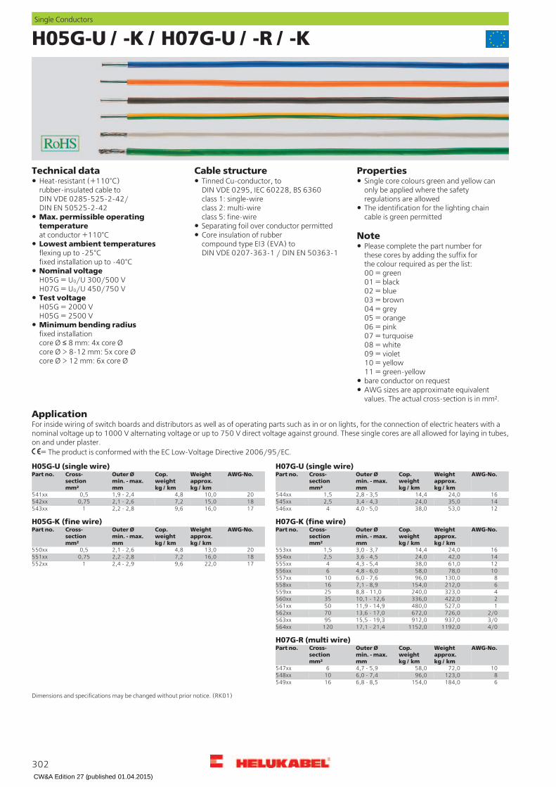
H05G-U / -K / H07G-U / -R / -K
PropertiesCable structureTechnical dataTinned Cu-conductor, toDIN VDE 0295, IEC 60228, BS 6360class 1: single-wireclass 2: multi-wireclass 5: fine-wire
Heat-resistant (+110°C)rubber-insulated cable toDIN VDE 0285-525-2-42/DIN EN 50525-2-42
Single core colours green and yellow canonly be applied where the safetyregulations are allowedThe identification for the lighting chaincable is green permittedMax. permissible operating
temperatureat conductor +110°C
Note
Separating foil over conductor permittedCore insulation of rubbercompound type EI3 (EVA) toDIN VDE 0207-363-1 / DIN EN 50363-1
Lowest ambient temperaturesflexing up to -25°Cfixed installation up to -40°C
Please complete the part number forthese cores by adding the suffix forthe colour required as per the list:00 = green01 = black02 = blue03 = brown04 = grey05 = orange06 = pink07 = turquoise08 = white09 = violet10 = yellow11 = green-yellow
Nominal voltageH05G = U0/U 300/500 VH07G = U0/U 450/750 VTest voltageH05G = 2000 VH05G = 2500 VMinimum bending radiusfixed installationcore Ø 8 mm: 4x core Øcore Ø > 8-12 mm: 5x core Øcore Ø > 12 mm: 6x core Ø
bare conductor on requestAWG sizes are approximate equivalentvalues. The actual cross-section is in mm².
ApplicationFor inside wiring of switch boards and distributors as well as of operating parts such as in or on lights, for the connection of electric heaters with anominal voltage up to 1000 V alternating voltage or up to 750 V direct voltage against ground. These single cores are all allowed for laying in tubes,on and under plaster.
= The product is conformed with the EC Low-Voltage Directive 2006/95/EC.
H07G-U (single wire)H05G-U (single wire)AWG-No.Weight
approx.kg / km
Cop.weightkg / km
Outer Ømin. - max.mm
Cross-sectionmm²
Part no. AWG-No.Weightapprox.kg / km
Cop.weightkg / km
Outer Ømin. - max.mm
Cross-sectionmm²
Part no.
2010,04,81,9 - 2,40,5541xx 1624,014,42,8 - 3,51,5544xx1815,07,22,1 - 2,60,75542xx 1435,024,03,4 - 4,32,5545xx1716,09,62,2 - 2,81543xx 1253,038,04,0 - 5,04546xx
H05G-K (fine wire) H07G-K (fine wire)AWG-No.Weight
approx.kg / km
Cop.weightkg / km
Outer Ømin. - max.mm
Cross-sectionmm²
Part no.AWG-No.Weightapprox.kg / km
Cop.weightkg / km
Outer Ømin. - max.mm
Cross-sectionmm²
Part no.
1624,014,43,0 - 3,71,5553xx2013,04,82,1 - 2,60,5550xx1442,024,03,6 - 4,52,5554xx1816,07,22,2 - 2,80,75551xx1261,038,04,3 - 5,44555xx1722,09,62,4 - 2,91552xx1078,058,04,8 - 6,06556xx
8130,096,06,0 - 7,610557xx6212,0154,07,1 - 8,916558xx4323,0240,08,8 - 11,025559xx2422,0336,010,1 - 12,635560xx1527,0480,011,9 - 14,950561xx
2/0726,0672,013,6 - 17,070562xx3/0937,0912,015,5 - 19,395563xx4/01192,01152,017,1 - 21,4120564xx
H07G-R (multi wire)AWG-No.Weight
approx.kg / km
Cop.weightkg / km
Outer Ømin. - max.mm
Cross-sectionmm²
Part no.
1072,058,04,7 - 5,96547xx8123,096,06,0 - 7,410548xx6184,0154,06,8 - 8,516549xx
Dimensions and specifications may be changed without prior notice. (RK01)
302
Single Conductors
CW&A Edition 27 (published 01.04.2015)
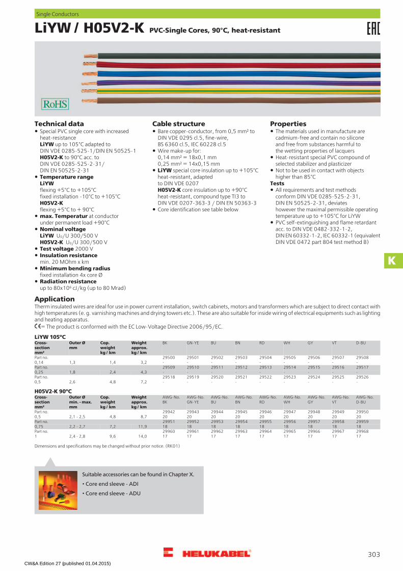
LiYW / H05V2-K PVC-Single Cores, 90°C, heat-resistant
PropertiesCable structureTechnical dataBare copper-conductor, from 0,5 mm² toDIN VDE 0295 cl.5, fine-wire,BS 6360 cl.5, IEC 60228 cl.5
Special PVC single core with increasedheat-resistanceLiYW up to 105°C adapted toDIN VDE 0285-525-1/DIN EN 50525-1H05V2-K to 90°C acc. toDIN VDE 0285-525-2-31/DIN EN 50525-2-31
The materials used in manufacture arecadmium-free and contain no siliconeand free from substances harmful tothe wetting properties of lacquersWire make-up for:
0,14 mm² = 18x0,1 mm0,25 mm² = 14x0,15 mm
Heat-resistant special PVC compound ofselected stabilizer and plasticizer
LiYW special core insulation up to +105°Cheat-resistant, adaptedto DIN VDE 0207H05V2-K core insulation up to +90°Cheat-resistant, compound type TI3 toDIN VDE 0207-363-3 / DIN EN 50363-3
Not to be used in contact with objectshigher than 85°CTemperature range
LiYWflexing +5°C to +105°Cfixed installation -10°C to +105°CH05V2-Kflexing +5°C to + 90°C
TestsAll requirements and test methodsconform DIN VDE 0285-525-2-31,DIN EN 50525-2-31, deviateshowever the maximal permissible operatingtemperature up to +105°C for LiYW
Core identification see table belowmax. Temperatur at conductorunder permanent load +90°C PVC self-extinguishing and flame retardant
acc. to DIN VDE 0482-332-1-2,DIN EN 60332-1-2, IEC 60332-1 (equivalentDIN VDE 0472 part 804 test method B)
Nominal voltageLiYW U0/U 300/500 VH05V2-K U0/U 300/500 VTest voltage 2000 VInsulation resistancemin. 20 MOhm x kmMinimum bending radiusfixed installation 4x core ØRadiation resistanceup to 80x106 cJ/kg (up to 80 Mrad)
ApplicationTherm insulated wires are ideal for use in power current installation, switch cabinets, motors and transformers which are subject to direct contact withhigh temperatures (e. g. varnishing machines and drying towers etc.). These are also suitable for inside wiring of electrical equipments such as lightingand heating apparatus.
= The product is conformed with the EC Low-Voltage Directive 2006/95/EC.
LiYW 105ºCD-BUVTGYWHRDBNBUGN-YEBKWeight
approx.kg / km
Cop.weightkg / km
Outer Ømm
Cross-sectionmm²
295082950729506295052950429503295022950129500Part no.---------3,21,41,30,14295172951629515295142951329512295112951029509Part no.---------4,32,41,80,25295262952529524295232952229521295202951929518Part no.---------7,24,82,60,5
H05V2-K 90ºCAWG-No.D-BU
AWG-No.VT
AWG-No.GY
AWG-No.WH
AWG-No.RD
AWG-No.BN
AWG-No.BU
AWG-No.GN-YE
AWG-No.BK
Weightapprox.kg / km
Cop.weightkg / km
Outer Ømin. - max.mm
Cross-sectionmm²
299502994929948299472994629945299442994329942Part no.2020202020202020208,74,82,1 - 2,50,5299592995829957299562995529954299532995229951Part no.18181818181818181811,97,22,2 - 2,70,75299682996729966299652996429963299622996129960Part no.17171717171717171714,09,62,4 - 2,81
Dimensions and specifications may be changed without prior notice. (RK01)
303
Single Conductors
K
Suitable accessories can be found in Chapter X.
• Core end sleeve - ADI
• Core end sleeve - ADU
CW&A Edition 27 (published 01.04.2015)
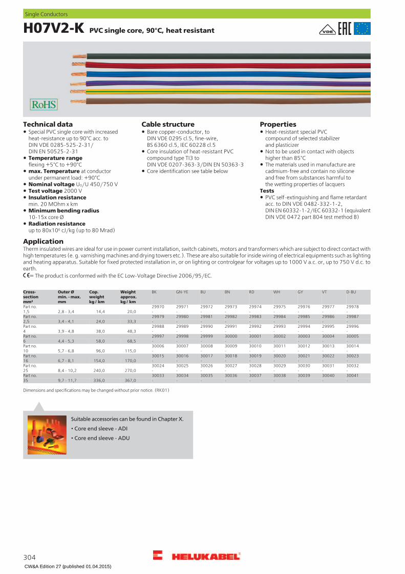
H07V2-K PVC single core, 90°C, heat resistant
PropertiesCable structureTechnical dataBare copper-conductor, toDIN VDE 0295 cl.5, fine-wire,BS 6360 cl.5, IEC 60228 cl.5
Special PVC single core with increasedheat-resistance up to 90°C acc. toDIN VDE 0285-525-2-31/DIN EN 50525-2-31
Heat-resistant special PVCcompound of selected stabilizerand plasticizerNot to be used in contact with objectshigher than 85°C
Core insulation of heat-resistant PVCcompound type TI3 toDIN VDE 0207-363-3/DIN EN 50363-3
Temperature rangeflexing +5°C to +90°C The materials used in manufacture are
cadmium-free and contain no siliconeand free from substances harmful tothe wetting properties of lacquers
Core identification see table belowmax. Temperature at conductorunder permanent load: +90°CNominal voltage U0/U 450/750 V
TestsTest voltage 2000 VPVC self-extinguishing and flame retardantacc. to DIN VDE 0482-332-1-2,DIN EN 60332-1-2/IEC 60332-1 (equivalentDIN VDE 0472 part 804 test method B)
Insulation resistancemin. 20 MOhm x kmMinimum bending radius10-15x core ØRadiation resistanceup to 80x106 cJ/kg (up to 80 Mrad)
ApplicationTherm insulated wires are ideal for use in power current installation, switch cabinets, motors and transformers which are subject to direct contact withhigh temperatures (e. g. varnishing machines and drying towers etc.). These are also suitable for inside wiring of electrical equipments such as lightingand heating apparatus. Suitable for fixed protected installation in, or on lighting or controlgear for voltages up to 1000 V a.c. or, up to 750 V d.c. toearth.
= The product is conformed with the EC Low-Voltage Directive 2006/95/EC.
D-BUVTGYWHRDBNBUGN-YEBKWeight
approx.kg / km
Cop.weightkg / km
Outer Ømin. - max.mm
Cross-sectionmm²
299782997729976299752997429973299722997129970Part no.---------20,014,42,8 - 3,41,5299872998629985299842998329982299812998029979Part no.---------33,324,03,4 - 4,12,5299962999529994299932999229991299902998929988Part no.---------48,338,03,9 - 4,84300053000430003300023000130000299992999829997Part no.---------68,558,04,4 - 5,36300143001330012300113001030009300083000730006Part no.---------115,096,05,7 - 6,810300233002230021300203001930018300173001630015Part no.---------170,0154,06,7 - 8,116300323003130030300293002830027300263002530024Part no.---------270,0240,08,4 - 10,225300413004030039300383003730036300353003430033Part no.---------367,0336,09,7 - 11,735
Dimensions and specifications may be changed without prior notice. (RK01)
304
Single Conductors
Suitable accessories can be found in Chapter X.
• Core end sleeve - ADI
• Core end sleeve - ADU
CW&A Edition 27 (published 01.04.2015)
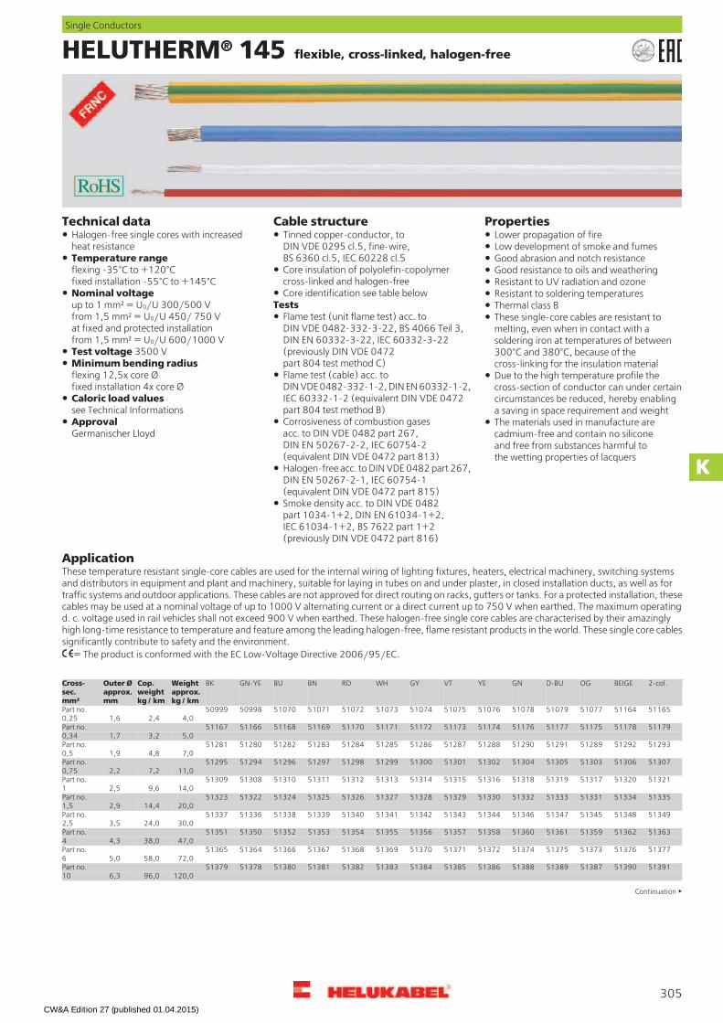
HELUTHERM® 145 flexible, cross-linked, halogen-free
PropertiesCable structureTechnical dataTinned copper-conductor, toDIN VDE 0295 cl.5, fine-wire,BS 6360 cl.5, IEC 60228 cl.5
Halogen-free single cores with increasedheat resistance
Lower propagation of fireLow development of smoke and fumes
Temperature rangeflexing -35°C to +120°Cfixed installation -55°C to +145°C
Good abrasion and notch resistanceCore insulation of polyolefin-copolymercross-linked and halogen-free
Good resistance to oils and weatheringResistant to UV radiation and ozone
Core identification see table belowNominal voltageup to 1 mm² = U0/U 300/500 Vfrom 1,5 mm² = U0/U 450/ 750 Vat fixed and protected installationfrom 1,5 mm² = U0/U 600/1000 V
Resistant to soldering temperaturesTests Thermal class B
Flame test (unit flame test) acc. toDIN VDE 0482-332-3-22, BS 4066 Teil 3,DIN EN 60332-3-22, IEC 60332-3-22(previously DIN VDE 0472part 804 test method C)
These single-core cables are resistant tomelting, even when in contact with asoldering iron at temperatures of between300°C and 380°C, because of thecross-linking for the insulation material
Test voltage 3500 VMinimum bending radiusflexing 12,5x core Øfixed installation 4x core Ø
Flame test (cable) acc. toDIN VDE 0482-332-1-2, DIN EN 60332-1-2,IEC 60332-1-2 (equivalent DIN VDE 0472part 804 test method B)
Due to the high temperature profile thecross-section of conductor can under certaincircumstances be reduced, hereby enablinga saving in space requirement and weight
Caloric load valuessee Technical Informations
Corrosiveness of combustion gasesacc. to DIN VDE 0482 part 267,DIN EN 50267-2-2, IEC 60754-2(equivalent DIN VDE 0472 part 813)
ApprovalGermanischer Lloyd
The materials used in manufacture arecadmium-free and contain no siliconeand free from substances harmful tothe wetting properties of lacquers
Halogen-free acc. to DIN VDE 0482 part 267,DIN EN 50267-2-1, IEC 60754-1(equivalent DIN VDE 0472 part 815)Smoke density acc. to DIN VDE 0482part 1034-1+2, DIN EN 61034-1+2,IEC 61034-1+2, BS 7622 part 1+2(previously DIN VDE 0472 part 816)
ApplicationThese temperature resistant single-core cables are used for the internal wiring of lighting fixtures, heaters, electrical machinery, switching systemsand distributors in equipment and plant and machinery, suitable for laying in tubes on and under plaster, in closed installation ducts, as well as fortraffic systems and outdoor applications. These cables are not approved for direct routing on racks, gutters or tanks. For a protected installation, thesecables may be used at a nominal voltage of up to 1000 V alternating current or a direct current up to 750 V when earthed. The maximum operatingd. c. voltage used in rail vehicles shall not exceed 900 V when earthed. These halogen-free single core cables are characterised by their amazinglyhigh long-time resistance to temperature and feature among the leading halogen-free, flame resistant products in the world. These single core cablessignificantly contribute to safety and the environment.
= The product is conformed with the EC Low-Voltage Directive 2006/95/EC.
Weightapprox.kg / km
Cop.weightkg / km
Outer Øapprox.mm
Cross-sec.mm²
2-col.BEIGEOGD-BUGNYEVTGYWHRDBNBUGN-YEBK
5116551164510775107951078510765107551074510735107251071510705099850999Part no.4,02,41,60,25
5117951178511755117751176511745117351172511715117051169511685116651167Part no.5,03,21,70,34
5129351292512895129151290512885128751286512855128451283512825128051281Part no.7,04,81,90,5
5130751306513035130551304513025130151300512995129851297512965129451295Part no.11,07,22,20,75
5132151320513175131951318513165131551314513135131251311513105130851309Part no.14,09,62,51
5133551334513315133351332513305132951328513275132651325513245132251323Part no.20,014,42,91,5
5134951348513455134751346513445134351342513415134051339513385133651337Part no.30,024,03,52,5
5136351362513595136151360513585135751356513555135451353513525135051351Part no.47,038,04,34
5137751376513735137551374513725137151370513695136851367513665136451365Part no.72,058,05,06
5139151390513875138951388513865138551384513835138251381513805137851379Part no.120,096,06,310
Continuation
305
Single Conductors
K
CW&A Edition 27 (published 01.04.2015)
HELUTHERM® 145 flexible, cross-linked, halogen-free
Weightapprox.kg / km
Cop.weightkg / km
Outer Øapprox.mm
Cross-sec.mm²
2-col.BEIGEOGD-BUGNYEVTGYWHRDBNBUGN-YEBK
5143251431514285143051429514275142651425514245142351422514215141951420Part no.182,0154,07,316
5144651445514425144451443514415144051439514385143751436514355143351434Part no.272,0240,09,625
5146051459514565145851457514555145451453514525145151450514495144751448Part no.371,0336,010,835
5147451473514705147251471514695146851467514665146551464514635146151462Part no.530,0480,012,650
5148851487514845148651485514835148251481514805147951478514775147551476Part no.730,0672,014,670
5150251501514985150051499514975149651495514945149351492514915148951490Part no.964,0912,016,595
5151651515515125151451513515115151051509515085150751506515055150351504Part no.1235,01152,018,0120
5153051529515265152851527515255152451523515225152151520515195151751518Part no.1523,01440,020,0150
5154451543515405154251541515395153851537515365153551534515335153151532Part no.1850,01776,022,2185
5155851557515545155651555515535155251551515505154951548515475154551546Part no.2432,02304,024,5240
Dimensions and specifications may be changed without prior notice. (RK01)
306
Single Conductors
Suitable accessories can be found in Chapter X.
• Core end sleeve - ADI
• Core end sleeve - ADU
CW&A Edition 27 (published 01.04.2015)

SiF / SiFF silicon single cores, halogen-free
PropertiesCable structureType SiF
Technical dataSpezial-silicon single core with higherheat-resistance range adapted toDIN VDE 0250 Teil 1 and part 502
Resistant tohigh molecular oils, fats from vegetables andanimals, alcohols, plasticizers and clophenes,diluted acids, lyes and salt dissolution,oxidation substances, tropical influences andweather, lake water, oxygen
Tinned copper-conductor,from 0,5 mm² toDIN VDE 0295 cl.5, fine-wire,BS 6360 cl.5, IEC 60228 cl.5Temperatue range
-60°C to +180°C(up to +220°C for short time)
Conductor construction0,25 mm² = 14x0,15 mm
Temperature limit at the conductorin operation +180°C
Core insulation of silicone High flash pointsType SiFF For laying as a fixed installation only in open
or ventilated pipe systems as well as inducts. Otherwise the mechanical propertiesof the silicon are reduced by the enclosedair at temperatures exceeding 90°C.
Nominal voltage U0/U 300/500 V Tinned Cu-conductor, toDIN VDE 0295 cl.6, extra fine-wire,BS 6360 cl.6, IEC 60228 cl.6(single wire Ø 0,07 mm)
Test voltage 2000 VBreakdown voltage min. 5000 VMinimum bending radius6x core Ø TestsCore insulation of silicone
Corrosiveness of combustion gases(Halogen-free) acc. to DIN VDE 0482part 267, DIN EN 50267-2-2,IEC 60754-2 (equivalentDIN VDE 0472 part 813)
Radiation resistanceup to 20 x 106 cJ/kg (up to 20 Mrad)
Behaviour in fire no flame propagationacc. to DIN VDE 0482-332-1-2,DIN EN 60332-1-2,IEC 60332-1 (equivalentDIN VDE 0472 part 804 test method B)
Note
Please complete the part number for thesecables by adding the suffix for the colourrequired as per the list:00 = green, 01 = black, 02 = red,03 = blue, 04 = brown, 05 = white,06 = grey, 07 = violet, 08 = yellow,09 = orange, 10 = transparent,11 = pink, 12 = beige, 13 = 2-colourAWG sizes are approximate equivalentvalues. The actual cross-section is in mm².
ApplicationSpecial single cores for use in high, resp. low temperature areas. They are used mainly in the steel producing industries, in aviation industries as wellas in ship building, cement, glas and ceramic factories. As this single cores are halogen-free, especially suited for use in power stations.
= The product is conformed with the EC Low-Voltage Directive 2006/95/EC.
SiFFSiFAWG-No.Weight
approx.kg / km
Cop.weightkg / km
Outer Øapprox. mm
Cross-sectionmm²
Part no. AWG-No.Weightapprox.kg / km
Cop.weightkg / km
Outer Øapprox. mm
Cross-sectionmm²
Part no.
245,52,41,90,25232xx 246,02,41,90,25451xx208,64,82,10,5233xx 2010,04,82,20,5452xx1811,87,22,40,75234xx 1813,07,22,50,75453xx1713,59,62,51235xx 1715,09,62,61454xx1618,514,42,81,5236xx 1619,014,43,11,5455xx1430,024,03,42,5237xx 1432,024,03,72,5456xx1247,338,04,24238xx 1250,038,04,44457xx1071,158,05,06239xx 1073,058,05,26458xx
8119,496,06,610246xx 8125,096,06,810459xx6187,7154,07,416247xx4289,6240,09,225248xx
SiF (wire colour black)AWG-No.Weight
approx.kg / km
Cop.weightkg / km
Outer Øapprox. mm
Cross-sectionmm²
Part no.
2398,3336,010,335239531559,7480,011,85023954
2/0765,8672,013,670239553/01031,5912,015,695239564/01284,61152,017,612023957
300 kcmil1563,41440,019,615023958350 kcmil1858,21776,022,418523959
Dimensions and specifications may be changed without prior notice. (RK01)
307
Single Conductors
K
CW&A Edition 27 (published 01.04.2015)

SiF/GL, SiD, SiD/GL silicon single cores, halogen-free
PropertiesCable structureType SiF/GL
Technical dataSpezial-silicon single core with higherheat-resistance range adapted toDIN VDE 0250 Teil 1 and part 502
Resistant tohigh molecular oils, fats from vegetablesand animals, alcohols, plasticizers andclophenes, diluted acids, lyes and saltdissolution, oxidation substances, tropicalinfluences and weather, lake water, oxygen
Tinned copper-conductor, from 0,5 mm² toDIN VDE 0295 cl.5, fine-wire,BS 6360 cl.5, IEC 60228 cl.5Temperatue range
-60°C to +180°C(for short time +220°C)
Conductor construction:0,25 mm² = 14x0,15 mm
Temperature limit at the conductorin operation +180°C
Core insulation of silicone High flash pointsFor laying as a fixed installation only in openor ventilated pipe systems as well as inducts. Otherwise the mechanical propertiesof the silicon are reduced by the enclosedair at temperatures exceeding 90°C.
Glass-fibre braidingNominal voltage U0/U 300/500 V Type SiDTest voltage 2000 V Tinned copper-conductor, single-wireBreakdown voltage min. 5000 V Core insulation of siliconeMinimum bending radius15x core Ø(SID only for permanent installation)
Type SiD/GLTestsTinned copper-conductor, single-wire
Corrosiveness of combustion gases(Halogen-free) acc. to DIN VDE 0482part 267, DIN EN 50267-2-2,IEC 60754-2 (equivalentDIN VDE 0472 part 813)
Core insulation of siliconeRadiation resistanceup to 20 x 106 cJ/kg (up to 20 Mrad)
Glass-fibre braiding
Behaviour in fire no flame propagationacc. to DIN VDE 0482-332-1-2,DIN EN 60332-1-2,IEC 60332-1 (equivalentDIN VDE 0472 part 804 test method B)
Note
Please complete the part number for thesecables by adding the suffix for the colourrequired as per the list:00 = green, 01 = black, 02 = red,03 = blue, 04 = brown, 05 = white,06 = grey, 07 = violet, 08 = yellow,09 = orange, 10 = transparent,11 = pink, 12 = beige, 13 = 2-colourAWG sizes are approximate equivalentvalues. The actual cross-section is in mm².
ApplicationSpecial single cores for use in high, resp. low temperature areas. They are used mainly in the steel producing industries, in aviation industries as wellas in ship building, cement, glas and ceramic factories. As this single cores are halogen-free, especially suited for use in power stations.
= The product is conformed with the EC Low-Voltage Directive 2006/95/EC.
SiDSiF/GLAWG-No.Weight
approx.kg / km
Cop.weightkg / km
Outer Øapprox. mm
Cross-sectionmm²
Part no. AWG-No.Weightapprox.kg / km
Cop.weightkg / km
Outer Øapprox. mm
Cross-sectionmm²
Part no.
247,72,42,40,2547001 -4,21,91,70,2461xx2012,44,82,50,547002 -5,12,71,80,28462xx1816,27,22,80,7547003 207,54,82,00,5463xx1718,29,62,9147004 1810,27,22,10,75464xx1623,414,43,21,547005 1712,69,62,31465xx1435,224,03,82,547006 1618,114,42,51,5466xx1253,538,04,6447007 1428,724,03,22,5467xx1077,458,05,4647008 1245,238,03,94468xx
8129,296,07,61047009 1064,358,04,46469xx
6198,4154,08,41647010SiD/GL4303,0240,010,22547011
AWG-No.Weightapprox.kg / km
Cop.weightkg / km
Outer Øapprox. mm
Cross-sectionmm²
Part no.2413,2336,011,335470121577,8480,013,45047013
2010,04,82,40,5470141815,07,22,60,75470151719,09,62,71470161628,014,43,01,5470171440,024,03,62,5470181255,036,04,34470191080,058,05,0647020
Dimensions and specifications may be changed without prior notice. (RK01)
308
Single Conductors
CW&A Edition 27 (published 01.04.2015)

FZ-LSi / FZ-LS / Neon Light Cables
PropertiesCable structureFZ-LSi, blue
Technical dataFZ-LSi, blue Neon-light-cable, yellow
Test voltage 20 kV Halogen-freeacc. to DIN VDE 0482 part 267,DIN EN 50267-2-2, IEC 60754-2(equivalent DIN VDE 0472 part 813)
Tinned copper-conductorConductor consturction see table belowBreakdown voltage min. 30 kVCore insulation of siliconecompound type 2GI1 toDIN VDE 0207 part 20
Ignition voltage (kV eff.)0,5 mm² = 6 kV1,0 mm² = 8 kV1,5 mm² = 10 kV
Behaviour in fire no flame propagationacc. to DIN VDE 0482-332-1-2,DIN EN 60332-1-2,IEC 60332-1 (equivalentDIN VDE 0472 part 804 test method B)
Glass-fibre braidingFZ-LS, red Outer sheath of silicone
compound type 2GM1 toDIN VDE 0207 part 21
Test voltagefor 5 mm Ø = 15 kVfor 7 mm Ø = 20 kV
No formation of corrosive gasesLow smoke densitySheath colour blueVery good weather resistanceFZ-LS, redBreakdown voltage
for 5 mm Ø = min. 25 kVfor 7 mm Ø = min. 35 kV
Note
Tinned copper-conductor, 19x0,25 mm ØCore insulation of siliconecompound type 2GI1 toDIN VDE 0207 part 20
Neon-light-Cable, yellow AWG sizes are approximate equivalentvalues. The actual cross-section is in mm².Nominal voltage
3,5 kV, 4,0 kV or 7,5 kV Sheath colour redbrownTest voltage 10 kV Neon-light-cable, yellowSpecific volume resistivitymin. 1012 Ohm x cm
in adapted to DIN VDE 0250 part 1+5Tinned copper-conductor, 30x0,25 mm
Minimum bending radius7,5x cable Ø
Core insulation of siliconecompound type 2GI1 toDIN VDE 0207 part 20Radiation resistance
up to 20x106 cJ/kg (up to 20 Mrad) Sheath colour yellow
ApplicationFZ-LSi, blueThis ignition cable is suitable for use at high and extremely alternating ambient temperatures up to +180°C. Applications include engine manufacturing,valve manufacturing and heating technology. As protection against mechanical damages a glass fibre braiding and a silicone sheath covers the coreinsulation.FZ-LS, redThis ignition cable is suitable for use at high and extremely alternating ambient temperatures up to +180°C. Applications include the lamp and lightingindustry and cooling and airconditioning technology.Neon-light-cable, yellowThis cable is primarily suitable for use at high and extremely alternating ambient temperatures such as in the lamp and lighting industry. Protectedinstallation is required.
FZ-LS high-voltage ignition cable 15 and 20kVFZ-LSi ignition cableAWG-No.Weight
approx.kg / km
Cop.weightkg / km
Outer Øapprox.mm
Cond.make-up(nom. val.)n x wire Ø
Cross-sec.mm²
Corecolour
Part no. AWG-No.Weightapprox.kg / km
Cop.weightkg / km
Outer Øapprox.mm
Cond.make-up(nom. val.)n x wire Ø
Cross-sec.mm²
Corecolour
Part no.
2036,04,85,07 x 0,30,5BU23110 1734,09,65,019 x 0,251red-brown231091760,09,67,019 x 0,251red-brown231081765,09,57,519 x 0,251BU23106
1688,014,48,528 x 0,261,5BU23107neon light cables (neon cable) 3,5kV, 4,0kV and 7,5kV
AWG-No.Weightapprox.kg / km
Cop.weightkg / km
Outer Øapprox.mm
Cond.make-up(nom. val.)n x wire Ø
Cross-sec.mm²
Corecolour
Part no.
1632,014,44,430 x 0,251,5YE231471659,014,46,630 x 0,251,5YE231481675,014,47,630 x 0,251,5YE23149
Dimensions and specifications may be changed without prior notice. (RK01)
309
Single Conductors
K
Suitable accessories can be found in Chapter X.
• Core end sleeve - ADI
• Core end sleeve - ADU
CW&A Edition 27 (published 01.04.2015)
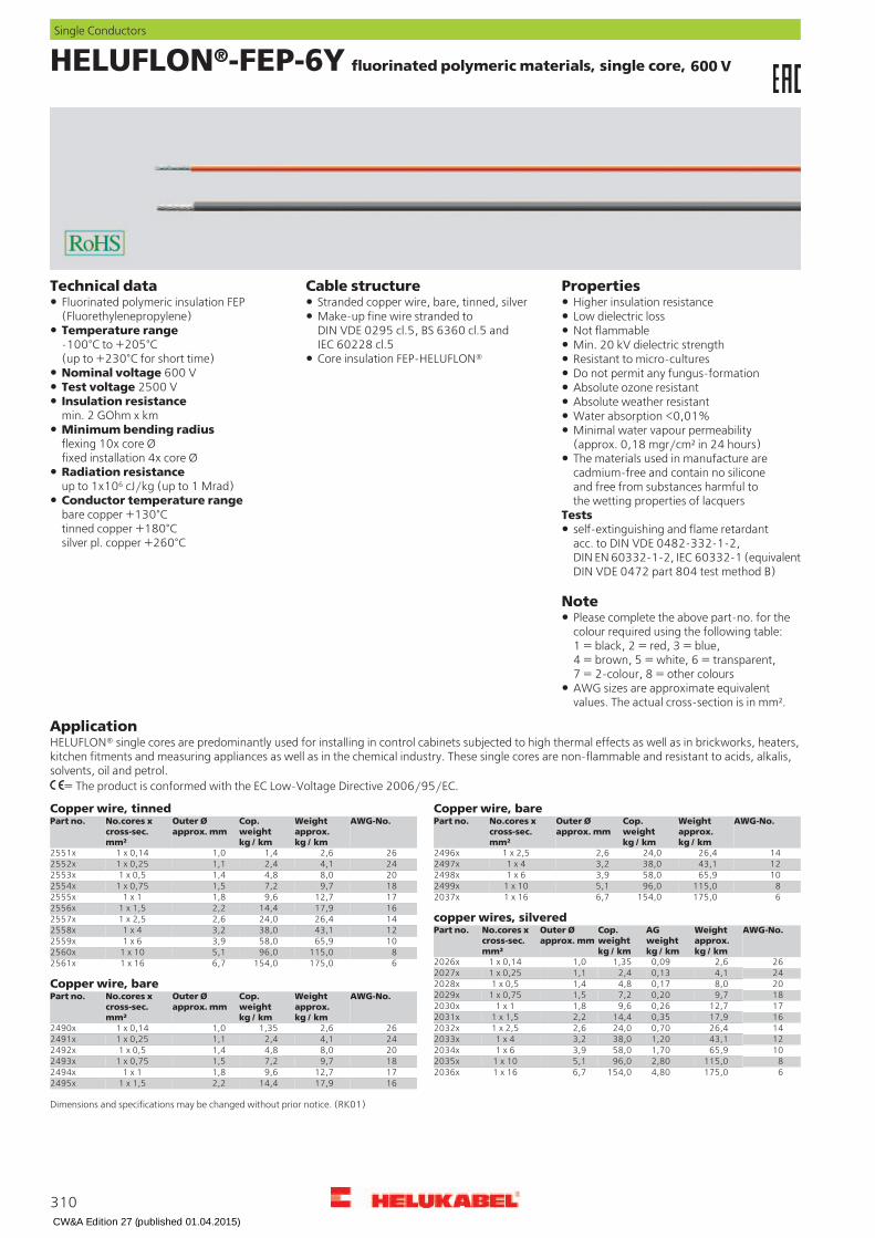
HELUFLON®-FEP-6Y fluorinated polymeric materials, single core, 600 V
PropertiesCable structureTechnical dataStranded copper wire, bare, tinned, silverFluorinated polymeric insulation FEP
(Fluorethylenepropylene)Higher insulation resistanceLow dielectric lossMake-up fine wire stranded to
DIN VDE 0295 cl.5, BS 6360 cl.5 andIEC 60228 cl.5
Temperature range-100°C to +205°C(up to +230°C for short time)
Not flammableMin. 20 kV dielectric strength
Core insulation FEP-HELUFLON® Resistant to micro-culturesNominal voltage 600 V Do not permit any fungus-formationTest voltage 2500 V Absolute ozone resistantInsulation resistancemin. 2 GOhm x km
Absolute weather resistantWater absorption <0,01%
Minimum bending radiusflexing 10x core Øfixed installation 4x core Ø
Minimal water vapour permeability(approx. 0,18 mgr/cm² in 24 hours)The materials used in manufacture arecadmium-free and contain no siliconeand free from substances harmful tothe wetting properties of lacquers
Radiation resistanceup to 1x10⁶ cJ/kg (up to 1 Mrad)Conductor temperature rangebare copper +130°Ctinned copper +180°Csilver pl. copper +260°C
Testsself-extinguishing and flame retardantacc. to DIN VDE 0482-332-1-2,DIN EN 60332-1-2, IEC 60332-1 (equivalentDIN VDE 0472 part 804 test method B)
Note
Please complete the above part-no. for thecolour required using the following table:1 = black, 2 = red, 3 = blue,4 = brown, 5 = white, 6 = transparent,7 = 2-colour, 8 = other coloursAWG sizes are approximate equivalentvalues. The actual cross-section is in mm².
ApplicationHELUFLON® single cores are predominantly used for installing in control cabinets subjected to high thermal effects as well as in brickworks, heaters,kitchen fitments and measuring appliances as well as in the chemical industry. These single cores are non-flammable and resistant to acids, alkalis,solvents, oil and petrol.
= The product is conformed with the EC Low-Voltage Directive 2006/95/EC.
Copper wire, bareCopper wire, tinnedAWG-No.Weight
approx.kg / km
Cop.weightkg / km
Outer Øapprox. mm
No.cores xcross-sec.mm²
Part no. AWG-No.Weightapprox.kg / km
Cop.weightkg / km
Outer Øapprox. mm
No.cores xcross-sec.mm²
Part no.
262,61,41,01 x 0,142551x 1426,424,02,61 x 2,52496x
244,12,41,11 x 0,252552x 1243,138,03,21 x 42497x
208,04,81,41 x 0,52553x 1065,958,03,91 x 62498x
189,77,21,51 x 0,752554x 8115,096,05,11 x 102499x
1712,79,61,81 x 12555x 6175,0154,06,71 x 162037x
1617,914,42,21 x 1,52556xcopper wires, silvered
1426,424,02,61 x 2,52557x
AWG-No.Weightapprox.kg / km
weightkg / km
Cop.weightkg / km
Outer Øapprox. mm
No.cores xcross-sec.mm²
Part no.1243,138,03,21 x 42558x
1065,958,03,91 x 62559x
8115,096,05,11 x 102560x262,60,091,351,01 x 0,142026x
6175,0154,06,71 x 162561x
244,10,132,41,11 x 0,252027x
Copper wire, bare
208,00,174,81,41 x 0,52028x
189,70,207,21,51 x 0,752029xAWG-No.Weightapprox.kg / km
Cop.weightkg / km
Outer Øapprox. mm
No.cores xcross-sec.mm²
Part no.
1712,70,269,61,81 x 12030x
1617,90,3514,42,21 x 1,52031x
262,61,351,01 x 0,142490x 1426,40,7024,02,61 x 2,52032x
1243,11,2038,03,21 x 42033x244,12,41,11 x 0,252491x
1065,91,7058,03,91 x 62034x208,04,81,41 x 0,52492x
8115,02,8096,05,11 x 102035x189,77,21,51 x 0,752493x
6175,04,80154,06,71 x 162036x1712,79,61,81 x 12494x
1617,914,42,21 x 1,52495x
Dimensions and specifications may be changed without prior notice. (RK01)
310
Single Conductors
AG
CW&A Edition 27 (published 01.04.2015)

HELUFLON®-PTFE-5Y fluorinated polymeric materials, single core,
600 V or 1000 V
PropertiesCable structureTechnical dataStranded copper wire, silverFluorinated polymeric insulation PTFE
(Polytetrafluorethylene)Higher insulation resistanceLow dielectric lossCore insulation PTFE-HELUFLON® to
DIN VDE 207 part 6Design to DIN VDE 0881 an IEC 60673 Not flammableTemperature range-190°C to +260°C(up to +300°C for short time)
PTFE as per MIL-W 16878 Resistant to micro-culturesDo not permit any fungus-formationAbsolute ozone resistant
Nominal voltagetype E = 600 Vtype EE = 1000 V
Absolute weather resistantWater absorption <0,01%Minimal water vapour permeability(approx. 0,18 mgr/cm² in 24 hours)Test voltage
type E = 3,4 kVtype EE = 5 kV
The materials used in manufacture arecadmium-free and contain no siliconeand free from substances harmful tothe wetting properties of lacquers
Insulation resistancemin. 1 GOhm x kmMinimum bending radius10x core Ø
Testsself-extinguishing and flame retardantacc. to DIN VDE 0482-332-1-2,DIN EN 60332-1-2, IEC 60332-1 (equivalentDIN VDE 0472 part 804 test method B)
Radiation resistanceup to 1x10⁵ cJ/kg (up to 0,1 Mrad)Conductor temperature rangebare copper +130°Ctinned copper +180°Csilver pl. copper +200°Cnickel pl. copper +260°C
Note
Please complete the above part-no. for thecolour required using the following table:1 = black, 2 = red, 3 = blue,4 = brown, 5 = white, 6 = transparent,7 = 2-colour, 8 = other colourConductor bare, tinned or nickel plated onrequest
ApplicationHELUFLON® single cores are predominantly used for installing in control cabinets subjected to high thermal effects as well as in brickworks, heaters,kitchen fitments and measuring appliances as well as in the chemical industry. These single cores are non-flammable and resistant to acids, alkalis,solvents, oil and petrol.
= The product is conformed with the EC Low-Voltage Directive 2006/95/EC.
1000 V600 VWeightapprox.kg / km
weightkg / km
Cop.weightkg / km
Outer Øapprox.mm
Cross-sectionmm²
No.cond.
AWG-No.Part no. Weightapprox.kg / km
weightkg / km
Cop.weightkg / km
Outer Øapprox.mm
Cross-sectionmm²
No.cond.
AWG-No.Part no.
0,40,030,40,700,037322511x 0,420,030,41,000,037322531x
0,590,040,60,810,067302512x 0,650,040,61,070,067302532x
0,930,060,90,890,097282513x 1,00,060,91,140,097282533x
1,470,071,40,990,147262514x 1,560,071,41,240,147262534x1,680,091,41,240,1419262535x1,580,091,40,990,1419262515x
2,40,072,31,370,217242536x2,310,072,31,120,217242516x
2,650,132,31,370,2419242537x2,520,132,31,120,2419242517x
3,850,103,51,520,357222538x3,680,103,51,270,357222518x
4,20,173,51,500,3819222539x3,990,173,51,270,3819222519x
6,30,125,61,720,577202540x6,00,125,61,470,577202520x6,40,186,11,470,5719202521x 6,90,186,11,720,5719202541x
9,450,229,61,740,907182522x 10,650,229,62,000,907182542x
10,20,279,61,740,9519182523x 13,650,279,62,000,9519182543x
12,90,2913,52,041,2319162524x 21,380,2913,52,261,2319162544x
20,30,3818,02,401,9419142525x 33,950,3818,02,761,9419142545x
Dimensions and specifications may be changed without prior notice. (RK01)
311
Single Conductors
K
AG AG
CW&A Edition 27 (published 01.04.2015)

HELUTHERM® 400 Insulation class C, halogen-free
PropertiesCable structureTechnical dataStranded nickel conductorSpecial core insulation mono or multi
colouredThese cables have very good electronic,chemical and radiation resistant propertiesOverlapping with special heat-resistant
impregnation Note
Temperature range-60°C to +400°Coperating temperature(up to +450°C for short time)
Colour identification through helix(colour see table) Also available with additional Kapton film
at extra cost.Nominal voltage 500 VTest voltage 2000 VMinimum bending radius15x outer ØRadiation resistanceup to 1x10¹⁰ cJ/kg (up to 1x10⁴ Mrad)
ApplicationThe wide temperature range offered by this cable type makes it especially suited for use in the aviation and aerospace industries, for atomic powerstations and in the steel making and chemical industries. For the critical applications, for example mechanical stress, we advise for consultation.
= The product is conformed with the EC Low-Voltage Directive 2006/95/EC.
2-col.TRANSBEIGEOGPKYEVTGYWHRDBNBUGN-YEBKNickel
weightkg / km
Outer Øapprox.mm
Conductorconstruction
Cross-sec.mm²
5091350910509125090950911509085090750906509055090450903509025090050901Part no.--------------4,82,216 x 0,20,55092750924509265092350925509225092150920509195091850917509165091450915Part no.--------------7,22,424 x 0,20,755094150938509405093750939509365093550934509335093250931509305092850929Part no.--------------9,62,732 x 0,215095550952509545095150953509505094950948509475094650945509445094250943Part no.--------------14,42,830 x 0,251,55096950966509685096550967509645096350962509615096050959509585095650957Part no.--------------24,03,450 x 0,252,55098350980509825097950981509785097750976509755097450973509725097050971Part no.--------------38,04,556 x 0,345099750994509965099350995509925099150990509895098850987509865098450985Part no.--------------58,04,984 x 0,365156251559515615089851560508975089650895508945089350892508915020950890Part no.--------------96,05,8141 x 0,3105157651573515755157251574515715157051569515685156751566515655156351564Part no.--------------154,07,4226 x 0,3165159051587515895158651588515855158451583515825158151580515795157751578Part no.--------------240,09,6196 x 0,4255160451601516035160051602515995159851597515965159551594515935159151592Part no.--------------336,011,5276 x 0,4355161851615516175161451616516135161251611516105160951608516075160551606Part no.--------------480,012,7396 x 0,4505163251629516315162851630516275162651625516245162351622516215161951620Part no.--------------672,016,0360 x 0,5705164651643516455164251644516415164051639516385163751636516355163351634Part no.--------------912,018,0485 x 0,5955166051657516595165651658516555165451653516525165151650516495164751648Part no.--------------1152,019,0608 x 0,51205167451671516735167051672516695166851667516665166551664516635166151662Part no.--------------1440,022,0756 x 0,51505168851685516875168451686516835168251681516805167951678516775167551676Part no.--------------1776,024,0944 x 0,51855170251699517015169851700516975169651695516945169351692516915168951690Part no.--------------2304,027,01222 x 0,5240
Dimensions and specifications may be changed without prior notice. (RK01)
312
Single Conductors
Suitable accessories can be found in Chapter X.
• Core end sleeve - ADI
• Core end sleeve - ADU
CW&A Edition 27 (published 01.04.2015)
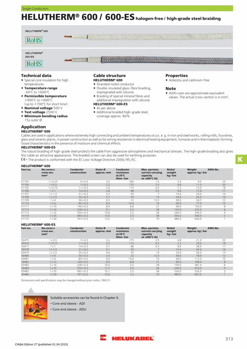
HELUTHERM® 600 / 600-ES halogen-free / high-grade steel braiding
PropertiesCable structureHELUTHERM® 600
Technical dataSpecial core insulation for hightemperatures
Asbestos and cadmium-free Stranded nickel conductor
Temperature range-60°C to +600°C
NoteDouble-insulated glass-fibre braiding,impregnated with silicone AWG sizes are approximate equivalent
values. The actual cross-section is in mm².Permissible temperature+400°C to +600°C(up to +700°C for short time)
Braiding of special mineral fibres andadditional impregnation with silicone
HELUTHERM® 600-ESNominal voltage 500 V As per aboveTest voltage 2500 V Additional braided high-grade steel,
coverage approx. 80%Minimum bending radius15x outer Ø
ApplicationHELUTHERM® 600Cables are used in applications where extremely high connecting and ambient temperatures occur, e. g. in iron and steel works, rolling mills, foundries,glass and ceramic plants, in power construction as well as for wiring resistances in electrical heating equipment, furnaces and in thermoplastic forming.Good characteristics in the presence of moisture and chemical effects.HELUTHERM® 600-ESThe robust braiding of high-grade steel protects the cable from aggressive atmospheres and mechanical stresses. The high-grade braiding also givesthis cable an attractive appearance. The braided screen can also be used for earthing purposes.
= The product is conformed with the EC Low-Voltage Directive 2006/95/EC.
HELUTHERM® 600AWG-No.Weight
approx. kg / kmNickelweightkg / km
Max. permiss.current carryingcapacityat +400°C (A)
Conductorresistanceat 20°COhm / km
Outer Øapprox. mm
Conductorconstruction
No.cores xcross-sec.mm²
Part no.
249,52,41,53462,04 x 0,31 x 0,25517032011,54,82,51752,37 x 0,31 x 0,5517041815,07,24,51152,611 x 0,31 x 0,75517051717,89,65,5882,814 x 0,31 x 1517061624,014,47593,221 x 0,31 x 1,5517071436,024,010353,735 x 0,31 x 2,5517081254,538,013,5224,556 x 0,31 x 4517091077,058,01614,66,084 x 0,31 x 651710
8150,096,0218,88,0140 x 0,31 x 10517116225,0154,0285,59,1228 x 0,31 x 16517124340,0240,0363,510,8354 x 0,31 x 25517132440,0336,0582,513,0495 x 0,31 x 35517141600,0480,0701,513,5707 x 0,31 x 5051715
HELUTHERM® 600-ESAWG-No.Weight
approx. kg / kmNickelweightkg / km
Max. permiss.current carryingcapacityat +400°C (A)
Conductorresistanceat 20°COhm / km
Outer Øapprox. mm
Conductorconstruction
No.cores xcross-sec.mm²
Part no.
2021,04,82,51753,27 x 0,31 x 0,5504751829,07,24,51153,511 x 0,31 x 0,75504761738,09,65,5883,714 x 0,31 x 1504771644,014,47594,121 x 0,31 x 1,5504781456,024,010354,635 x 0,31 x 2,5504791278,038,013,5225,456 x 0,31 x 45048010112,058,01614,66,984 x 0,31 x 650481
8198,096,0218,88,9140 x 0,31 x 10504826281,0154,0285,510,0228 x 0,31 x 16504834410,0240,0363,511,7354 x 0,31 x 25504842536,0336,0582,515,1495 x 0,31 x 35504851697,0480,0701,515,6707 x 0,31 x 5050486
Dimensions and specifications may be changed without prior notice. (RK01)
313
Single Conductors
K
Suitable accessories can be found in Chapter X.
• Core end sleeve - ADI
• Core end sleeve - ADU
CW&A Edition 27 (published 01.04.2015)

HELUTHERM® 800 / 800-ES halogen-free / high-grade steel braiding
PropertiesCable structureHELUTHERM® 800
Technical dataSpecial core insulation for hightemperatures
Asbestos and cadmium-free Stranded nickel conductor
Temperature range-120°C to +750°C
NoteDouble-insulated glass-fibre braiding,impregnated with silicone AWG sizes are approximate equivalent
values. The actual cross-section is in mm².Permissible temperature+600°C to +800°C(up to +1200°C for short time)
Braiding of special mineral fibres andadditional impregnation with silicone
HELUTHERM® 800-ESNominal voltage 500 V As per aboveTest voltage 2000 V Additional braided high-grade steel,
coverage approx. 80%Minimum bending radius15x outer Ø
ApplicationHELUTHERM® 800Cables are used in applications where extremely high connecting and ambient temperatures occur, e. g. in iron and steel works, rolling mills, foundries,glass and ceramic plants, in power construction as well as for wiring resistances in electrical heating equipment, furnaces and in thermoplastic forming.Good characteristics in the presence of moisture and chemical effects.HELUTHERM® 800-ESThe robust braiding of high-grade steel protects the cable from aggressive atmospheres and mechanical stresses. The high-grade braiding also givesthis cable an attractive appearance. The braided screen can also be used for earthing purposes.
= The product is conformed with the EC Low-Voltage Directive 2006/95/EC.
HELUTHERM® 800AWG-No.Weight
approx. kg / kmNickelweightkg / km
Max. permiss.current carryingcapacityat +700°C (A)
Conductorresistanceat 20°COhm / km
Outer Øapprox. mm
Conductorconstruction
No.cores xcross-sec.mm²
Part no.
2410,22,413462,24 x 0,31 x 0,25517162012,04,821752,37 x 0,31 x 0,5517171816,07,231152,911 x 0,31 x 0,75517181719,09,64883,214 x 0,31 x 1517191626,514,45593,221 x 0,31 x 1,5517201438,824,07353,735 x 0,31 x 2,5517211257,038,09224,556 x 0,31 x 4517221081,058,01214,65,984 x 0,31 x 651723
8156,096,0148,88,0140 x 0,31 x 10517246240,0154,0205,59,0228 x 0,31 x 16517254370,0240,0243,510,6354 x 0,31 x 25517262490,0336,0402,513,4495 x 0,31 x 35517271645,0480,0481,514,0707 x 0,31 x 5051728
HELUTHERM® 800-ESAWG-No.Weight
approx. kg / kmNickelweightkg / km
Max. permiss.current carryingcapacityat +700°C (A)
Conductorresistanceat 20°COhm / km
Outer Øapprox. mm
Conductorconstruction
No.cores xcross-sec.mm²
Part no.
2023,04,821753,57 x 0,31 x 0,5504881831,07,231153,811 x 0,31 x 0,75504891740,09,64884,114 x 0,31 x 1504901647,014,45594,521 x 0,31 x 1,5504911459,024,07354,935 x 0,31 x 2,5504921282,038,09225,856 x 0,31 x 45049310118,058,01214,67,384 x 0,31 x 650494
8209,096,0148,89,4140 x 0,31 x 10504956298,0154,0205,510,5228 x 0,31 x 16504964452,0240,0243,512,2354 x 0,31 x 25504972592,0336,0402,515,5495 x 0,31 x 35504981650,0480,0481,516,1707 x 0,31 x 5050499
Dimensions and specifications may be changed without prior notice. (RK01)
314
Single Conductors
Suitable accessories can be found in Chapter X.
• Core end sleeve - ADI
• Core end sleeve - ADU
CW&A Edition 27 (published 01.04.2015)
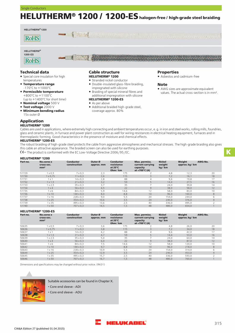
HELUTHERM® 1200 / 1200-ES halogen-free / high-grade steel braiding
PropertiesCable structureHELUTHERM® 1200
Technical dataSpecial core insulation for hightemperatures
Asbestos and cadmium-free Stranded nickel conductor
Temperature range-170°C to +1000°C
NoteDouble-insulated glass-fibre braiding,impregnated with silicone AWG sizes are approximate equivalent
values. The actual cross-section is in mm².Permissible temperature+800°C to +1100°C(up to +1400°C for short time)
Braiding of special mineral fibres andadditional impregnation with silicone
HELUTHERM® 1200-ESNominal voltage 500 V As per aboveTest voltage 2000 V Additional braided high-grade steel,
coverage approx. 80%Minimum bending radius15x outer Ø
ApplicationHELUTHERM® 1200Cables are used in applications, where extremely high connecting and ambient temperatures occur, e. g. in iron and steel works, rolling mills, foundries,glass and ceramic plants, in furnace and power plant construction as well for wiring resistances in electrical heating equipment, furnaces and inthermoplastic forming. Good characteristics in the presence of moisture and chemical effects.HELUTHERM® 1200-ESThe robust braiding of high-grade steel protects the cable from aggressive atmospheres and mechanical stresses. The high-grade braiding also givesthis cable an attractive appearance. The braided screen can also be used for earthing purposes.
= The product is conformed with the EC Low-Voltage Directive 2006/95/EC.
HELUTHERM® 1200AWG-No.Weight
approx. kg / kmNickelweightkg / km
Max. permiss.current carryingcapacityat +700°C (A)
Conductorresistanceat 20°COhm / km
Outer Øapprox. mm
Conductorconstruction
No.cores xcross-sec.mm²
Part no.
2012,34,821752,37 x 0,31 x 0,5517291816,17,231152,611 x 0,31 x 0,75517301719,89,64882,814 x 0,31 x 1517311627,514,45593,221 x 0,31 x 1,5517321439,824,07353,735 x 0,31 x 2,5517331258,038,09224,556 x 0,31 x 4517341083,058,01214,65,984 x 0,31 x 651735
8160,096,0148,88,0140 x 0,31 x 10517366244,0154,0205,59,0228 x 0,31 x 16517374376,0240,0243,510,6354 x 0,31 x 25517382495,0336,0402,513,6495 x 0,31 x 35517391654,0480,0481,514,5707 x 0,31 x 5051740
HELUTHERM® 1200-ESAWG-No.Weight
approx. kg / kmNickelweightkg / km
Max. permiss.current carryingcapacityat +700°C (A)
Conductorresistanceat 20°COhm / km
Outer Øapprox. mm
Conductorconstruction
No.cores xcross-sec.mm²
Part no.
2026,04,821753,67 x 0,31 x 0,5506351834,07,231153,811 x 0,31 x 0,75506361742,09,64884,214 x 0,31 x 1506371653,014,45594,721 x 0,31 x 1,5506381464,024,07355,035 x 0,31 x 2,5506391287,038,09226,056 x 0,31 x 45064010120,058,01214,67,584 x 0,31 x 650641
8218,096,0148,89,7140 x 0,31 x 10506426314,0154,0205,510,9228 x 0,31 x 16506434453,0240,0243,512,9354 x 0,31 x 25506442593,0336,0402,515,7495 x 0,31 x 35506451760,0480,0481,516,7707 x 0,31 x 5050646
Dimensions and specifications may be changed without prior notice. (RK01)
315
Single Conductors
K
Suitable accessories can be found in Chapter X.
• Core end sleeve - ADI
• Core end sleeve - ADU
CW&A Edition 27 (published 01.04.2015)

Earth Conductors ESUY and ESY
PropertiesCable structureESUY (H00V-D)
Technical dataESUY (H00 V-D) For these cable types no nominal voltages
are mentioned, as these are: only used forearthing performances
Earthing cable of braid wires overcore strands in adapted toDIN VDE 0283 part 3 and EN 61138
Bare copper-conductor, extra fine-wire,high flexible
For further requirements see EuropeanNorm EN 61230 and DIN VDE 0683 part 100:"Live working - Portable equipment forearthing and earthing"
Braiding of bare copper wires over thestranded copper conductorESYOuter sheath of PVCcompound type TM2 accordingDIN VDE 0207-363-4-1/DIN EN 50363-4-1
Earthing cable in adapted toDIN VDE 0283 part 3 and EN 61138
Note
ESUY (H00 V-D) and ESYSheath colour transparent (glass clear)Conductor resistance at 20°C
according DIN VDE 0283 part 3 ESY AWG sizes are approximate equivalentvalues. The actual cross-section is in mm².Bare Cu-conductor, fine-wireTemperature range
-5°C to +70°C Copper conductors of stranded wiresTest voltage 2000 V Outer sheath of PVC
compound type TM2 accordingDIN VDE 0207-363-4-1/DIN EN 50363-4-1
Spark test (during winding)16 mm² to 35 mm² = 5000 V50 mm² to 70 mm² = 6000 V95 mm² to 240 mm² = 8000 V
Sheath colour transparent (glass clear)
Insulation resistancemin. 20 MOhm x kmMinimal bending radius12x outer Ø
ApplicationESUY (H00V-D)These high flexible earth conductors are used for earthing of portable equipment and short-circuiting. These cables specially perform a protectivefunction in repair live working of high voltage power supply company as EVU, in railway systems, failing current equipment, alternating current systemsand in networks of transmission and distribution. Because of that these are designated as safety cables.ESYThese earthing cables offer special characteristics with low weights, high flexibility to a wide temperature range and the behavior in high temperature.The protective sheath over conductor assures the essential function for protection against the mechanical and chemical stresses.
ESUY (H00V-D), high flexibleAWG-No.Weight
approx. kg / kmCop.weightkg / km
Outer Øapprox. mm
Cond. make-upn x wire Ø
Cross-sectionmm²
Part no.
6230,0194,08,34200 x 0,0716289304335,0280,09,53192 x 0,125289312475,0415,011,24480 x 0,135289321670,0585,013,26383 x 0,15028933
2/0905,0820,015,68918 x 0,170289343/01220,01090,017,412100 x 0,195289354/01505,01360,019,815300 x 0,112028936
300 kcmil1940,01650,023,419152 x 0,115028937350 kcmil2390,02150,026,623580 x 0,118528938500 kcmil3090,02750,030,230600 x 0,124028939
ESY, flexibleAWG-No.Weight
approx. kg / kmCop.weightkg / km
Outer Øapprox. mm
Cond. make-upn x wire Ø
Cross-sectionmm²
Part no.
6185,0155,08,4525 x 0,216289404270,0240,09,8798 x 0,225289412390,0336,011,41120 x 0,235289421575,0480,013,81617 x 0,25028943
2/0810,0672,016,42254 x 0,270289443/01080,0912,018,23087 x 0,295289454/01320,01152,020,13822 x 0,212028946
300 kcmil1680,01440,023,04802 x 0,215028947
Dimensions and specifications may be changed without prior notice. (RK01)
316
Single Conductors
CW&A Edition 27 (published 01.04.2015)

GALVANICABLE®high-current cable, high flexible and halogen-free
PropertiesCable structureTechnical dataBare copper, ultra-fine wire conductorsacc. to DIN VDE 0295 cl.6 and IEC 60228cl.6
Temperature rangeflexing -40°C to +80°Cfixed installation -50°C to +80°C
PUR wearing sheath: extremely abrasionresistant, halogen-free, resistant to UV, oil,hydrolysis and microbial attackChemical resistance:PUR demonstrates significantly betterchemical resistance when compared withother materials, e.g. rubber or PVC
Extremely thick PUR wearing sheathNominal voltageU0/U 0,6/1 kV Natural colour, smooth, glossyTest voltage3500 V
The extremely thick polyurethane sheathstands for a longer life
Insulation resistancemin. 20 MOhm/kmMinimum bending radius15x cable Ø
ApplicationThis cable is employed as a highly-flexible high-current cathode cable for electroplating drum systems and as a wearing cable in the chemical industry.Special feature: Despite the extremely thick wearing sheath, the highly flexible conductor enables good contact when installing the pear push. Goodflexibility is likewise ensured when the pear push comes into contact with the parts to be electroplated.
= The product is conformed with the EC Low-Voltage Directive 2006/95/EC.
AWG-No.Weight
approx.kg / km
Cop.weightkg / km
Outer Øapprox. mm
No.cores xcross-sec.mm²
Part no. AWG-No.Weightapprox.kg / km
Cop.weightkg / km
Outer Øapprox. mm
No.cores xcross-sec.mm²
Part no.
2548,0336,017,21 x 35700768 4/01520,01152,027,01 x 120747491686,0480,019,01 x 5075497 300 kcmil2002,01440,028,01 x 150700769
2/0950,0672,021,51 x 7075498 350 kcmil2610,01776,030,51 x 1857007703/01386,0912,024,01 x 9575499 500 kcmil3820,02304,036,01 x 240700771
Dimensions and specifications may be changed without prior notice.
317
Single Conductors
K
Suitable accessories can be found in Chapter X.
• Core end sleeve - ADI
• Core end sleeve - ADU
CW&A Edition 27 (published 01.04.2015)

H01N2-D / H01N2-E 100 V, VDE approved, welding cable
PropertiesCable structureTechnical dataBare Cu- conductor, extra fine-wireto DIN VDE 0295, BS 6360, IEC 60228
Harmonized welding cable withrubber sheath, according toDIN VDE 0285-525-2-81 /DIN EN 50525-2-81
Test according to DIN VDE 0482-332-1-2,DIN EN 60332-1-2/ IEC 60332-1 (equivalentDIN VDE 0472 part 804 test method B)Separator over conductorOil resistant toDIN VDE 0473-811-404/ DIN EN60811-404
Neoprene outer sheath, chlorinatedrubber compound EM5Temperature range
flexing -25°C to +80°Cfixed installation -40°C to +80°C
Sheath colour blackThe cable also maintains its high flexibiltyunder the effect of ozone, light, oxygen,inert gas, oil or petrol
Without green-yellow markingAdmissible working temperatureat conductor +85°C
Nominal voltage U0/U 100/100 VNoteTest voltage 1000 V
Minimum bending radiusH01N2-D 12x outer ØH01N2-E 10x outer Ø
No. wires = Gauiding value;the number of individual wiresare without obligation.Tinned conductor on requestAWG sizes are approximate equivalentvalues. The actual cross-section is in mm².
ApplicationFor use between the welding generator and the hand-electrode and the workpiece. For use in the automobile industry, in shipbuilding, in transportand conveyor systems, tool making machinery, welding robots etc. These cables retain their high flexibility even under influence of ozone, light,oxygen, protective gases, oil and petrol. The robust construction makes these cables resistant to both to cold and the heat as well as to flames. Theyare suitable for use in open spaces and in dry and damp conditions.
= The product is conformed with the EC Low-Voltage Directive 2006/95/EC.
H01N2-D: Cables with standard flexibilityAWG-No.Weight
approx. kg / kmCop.weightkg / km
Outer Ømin. - max.mm
SheatNominal valuemm
No.wires xsingle wire Ømm
No.cores xcross-sec.mm²
Part no.
8135,096,07,7 - 9,72,0320 x 0,21 x 10310016205,0154,08,8 - 11,02,0512 x 0,21 x 16310024302,0240,010,1 - 12,72,0800 x 0,21 x 25310032420,0336,011,4 - 14,22,01120 x 0,21 x 35310041586,0480,013,2 - 16,52,21600 x 0,21 x 5031005
2/0798,0672,015,3 - 19,22,42240 x 0,21 x 70310063/01015,0912,017,1 - 21,42,63024 x 0,21 x 95310074/01310,01152,019,2 - 24,02,8614 x 0,51 x 12031008
300 kcmil1620,01440,021,2 - 26,43,0765 x 0,51 x 15031030350 kcmil1916,01776,023,1 - 28,93,2944 x 0,51 x 18531031500 kcmil2540,02304,025,0 - 29,53,41225 x 0,51 x 24031009
H01N2-E: Cables with extreme high flexibilityAWG-No.Weight
approx. kg / kmCop.weightkg / km
Outer Ømin. - max.mm
SheatNominal valuemm
No.wires xsingle wire Ømm
No.cores xcross-sec.mm²
Part no.
8119,096,06,2 - 7,81,2566 x 0,151 x 10310326181,0154,07,3 - 9,11,2903 x 0,151 x 16310334270,0240,08,6 - 10,81,21407 x 0,151 x 25310342363,0336,09,8 - 12,31,21974 x 0,151 x 35310351528,0480,011,9 - 14,81,52830 x 0,151 x 5031036
2/0716,0672,013,6 - 17,01,53952 x 0,151 x 70310373/01012,0912,015,6 - 19,51,85370 x 0,151 x 95310384/01190,01152,017,2 - 21,61,83819 x 0,21 x 12031039
300 kcmil1305,01440,018,8 - 23,51,84788 x 0,21 x 15031019350 kcmil1511,01776,020,4 - 25,51,85852 x 0,21 x 18531020
Dimensions and specifications may be changed without prior notice. (RK01)
318
Single Conductors
CW&A Edition 27 (published 01.04.2015)

NSGAFÖU 3kVSpecial Rubber-Insulated Cable, VDE approved, short-circuit
up to 1000 V
PropertiesCable structureTechnical dataTinned copper, fine wire conductors, bunchstranded to DIN VDE 0295 cl.5 andIEC 60228 cl.5
Special rubber-insulated single core cablesto DIN VDE 0250 part 602
Oil resistantTest to DIN VDE 0473-811-404/DIN EN 60811-404Temperature range
flexing -25°C to +80°Cfixed installation -40°C to +80°C
Behaviour in fireto DIN VDE 0482-332-1-2DIN EN 60332-2-1, IEC 60332-1 (equivalentDIN VDE 0472 part 804 test method B)
EPR-insulation, compound type 3GI3 toDIN VDE 0207 part 20Outer casing: Polychloroprene 5GM3acc. to DIN VDE 0207 part 21
Permissible operating temperatureat conductor +90°C
Colour black Considered as being short-circuit safe andinherently earth-fault-proof are thoseoperating materials and conductingassemblies where because of suitablemeasures and/or means applied, neither ashort circuit nor a short to ground is to beexpected under operating conditions whichare in accordance with those specified forthe intended application.
Nominal voltage U0/U 1,8/3 kVMax. permissible operating voltagein three and one-phase alternatingcurrent operation U0/U 2,1/3,6 kV, fordirect current operation U0/U 2,7/5,4 kVTest voltage 6 kVMinimum bending radiusflexing 10x outer Øfixed installation 6x outer Ø
Note
Version in 6 kV available on request.AWG sizes are approximate equivalentvalues. The actual cross-section is in mm².
ApplicationParticularly suitable for protection against short circuits in laying and for inherently earth-fault-proof routing in rail vehicles and omnibuses. Alsosuitable for laying in dry environments.
AWG-No.Weight
approx.kg / km
Cop.weightkg / km
Outer Øapprox. mm
No.cores xcross-sec.mm²
Part no. AWG-No.Weightapprox.kg / km
Cop.weightkg / km
Outer Øapprox. mm
No.cores xcross-sec.mm²
Part no.
1662,014,47,01 x 1,538501 1650,0480,018,01 x 5038509
1476,024,07,51 x 2,538502 2/0900,0672,020,51 x 7038510
1295,038,09,01 x 438503 3/01200,0912,024,01 x 9538511
10140,058,09,51 x 638504 4/01450,01152,026,01 x 12038513
8190,096,011,01 x 1038505 300 kcmil1800,01440,028,01 x 15038514
6270,0154,013,01 x 1638506 350 kcmil2200,01776,031,01 x 18538512
4410,0240,015,01 x 2538507 500 kcmil2650,02304,034,51 x 24038515
2490,0336,016,51 x 3538508 600 kcmil3250,02880,038,01 x 30038516
Dimensions and specifications may be changed without prior notice. (RK01)
319
Single Conductors
K
Suitable accessories can be found in Chapter X.
• Core end sleeve - ADI
• Core end sleeve - ADU
CW&A Edition 27 (published 01.04.2015)
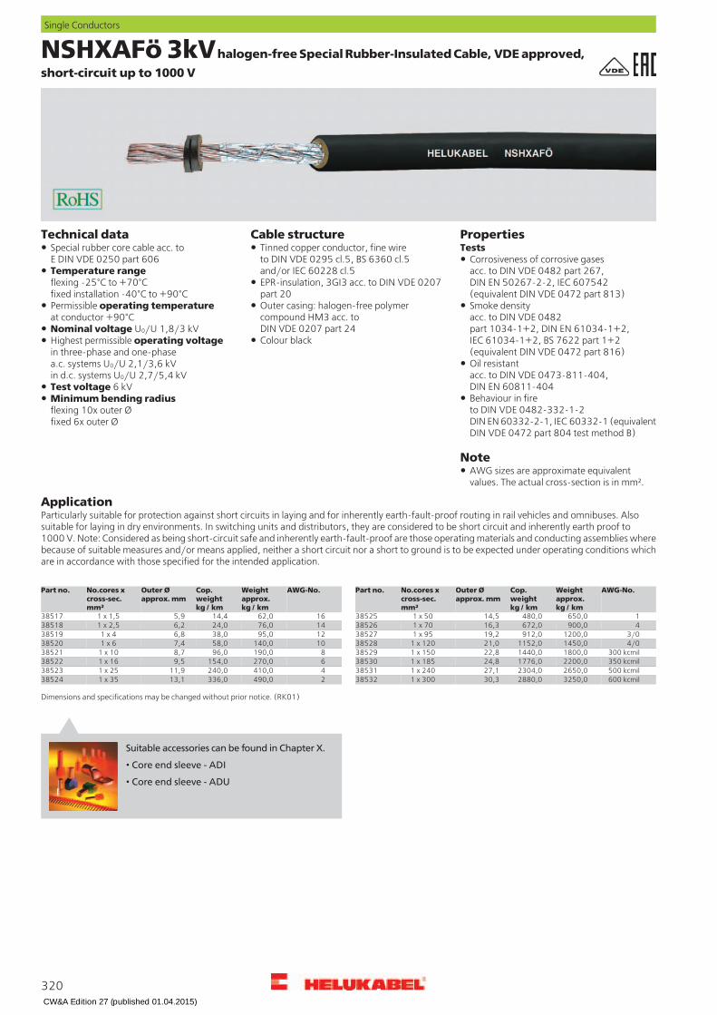
NSHXAFö 3kVhalogen-free Special Rubber-Insulated Cable, VDE approved,
short-circuit up to 1000 V
PropertiesCable structureTechnical dataTestsTinned copper conductor, fine wire
to DIN VDE 0295 cl.5, BS 6360 cl.5and/or IEC 60228 cl.5
Special rubber core cable acc. toE DIN VDE 0250 part 606 Corrosiveness of corrosive gases
acc. to DIN VDE 0482 part 267,DIN EN 50267-2-2, IEC 607542(equivalent DIN VDE 0472 part 813)
Temperature rangeflexing -25°C to +70°Cfixed installation -40°C to +90°C
EPR-insulation, 3GI3 acc. to DIN VDE 0207part 20Outer casing: halogen-free polymercompound HM3 acc. toDIN VDE 0207 part 24
Permissible operating temperatureat conductor +90°C
Smoke densityacc. to DIN VDE 0482part 1034-1+2, DIN EN 61034-1+2,IEC 61034-1+2, BS 7622 part 1+2(equivalent DIN VDE 0472 part 816)
Nominal voltage U0/U 1,8/3 kVColour blackHighest permissible operating voltage
in three-phase and one-phasea.c. systems U0/U 2,1/3,6 kVin d.c. systems U0/U 2,7/5,4 kV
Oil resistantacc. to DIN VDE 0473-811-404,DIN EN 60811-404Test voltage 6 kVBehaviour in fireto DIN VDE 0482-332-1-2DIN EN 60332-2-1, IEC 60332-1 (equivalentDIN VDE 0472 part 804 test method B)
Minimum bending radiusflexing 10x outer Øfixed 6x outer Ø
Note
AWG sizes are approximate equivalentvalues. The actual cross-section is in mm².
ApplicationParticularly suitable for protection against short circuits in laying and for inherently earth-fault-proof routing in rail vehicles and omnibuses. Alsosuitable for laying in dry environments. In switching units and distributors, they are considered to be short circuit and inherently earth proof to1000 V. Note: Considered as being short-circuit safe and inherently earth-fault-proof are those operating materials and conducting assemblies wherebecause of suitable measures and/or means applied, neither a short circuit nor a short to ground is to be expected under operating conditions whichare in accordance with those specified for the intended application.
AWG-No.Weight
approx.kg / km
Cop.weightkg / km
Outer Øapprox. mm
No.cores xcross-sec.mm²
Part no. AWG-No.Weightapprox.kg / km
Cop.weightkg / km
Outer Øapprox. mm
No.cores xcross-sec.mm²
Part no.
1662,014,45,91 x 1,538517 1650,0480,014,51 x 5038525
1476,024,06,21 x 2,538518 4900,0672,016,31 x 7038526
1295,038,06,81 x 438519 3/01200,0912,019,21 x 9538527
10140,058,07,41 x 638520 4/01450,01152,021,01 x 12038528
8190,096,08,71 x 1038521 300 kcmil1800,01440,022,81 x 15038529
6270,0154,09,51 x 1638522 350 kcmil2200,01776,024,81 x 18538530
4410,0240,011,91 x 2538523 500 kcmil2650,02304,027,11 x 24038531
2490,0336,013,11 x 3538524 600 kcmil3250,02880,030,31 x 30038532
Dimensions and specifications may be changed without prior notice. (RK01)
320
Single Conductors
Suitable accessories can be found in Chapter X.
• Core end sleeve - ADI
• Core end sleeve - ADU
CW&A Edition 27 (published 01.04.2015)
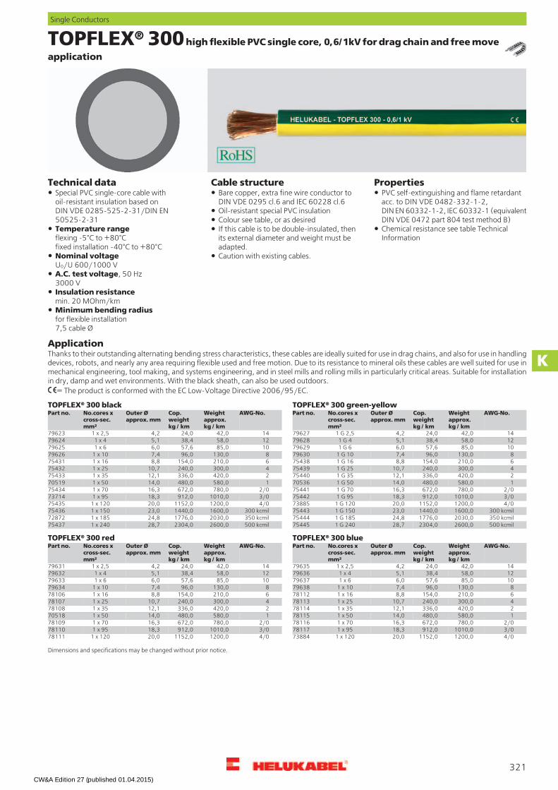
TOPFLEX® 300 high flexible PVC single core, 0,6/1kV for drag chain and free move
application
PropertiesCable structureTechnical dataBare copper, extra fine wire conductor toDIN VDE 0295 cl.6 and IEC 60228 cl.6
Special PVC single-core cable withoil-resistant insulation based onDIN VDE 0285-525-2-31/DIN EN50525-2-31
PVC self-extinguishing and flame retardantacc. to DIN VDE 0482-332-1-2,DIN EN 60332-1-2, IEC 60332-1 (equivalentDIN VDE 0472 part 804 test method B)
Oil-resistant special PVC insulationColour see table, or as desired
Chemical resistance see table TechnicalInformation
Temperature rangeflexing -5°C to +80°Cfixed installation -40°C to +80°C
If this cable is to be double-insulated, thenits external diameter and weight must beadapted.
Nominal voltageU0/U 600/1000 V
Caution with existing cables.
A.C. test voltage, 50 Hz3000 VInsulation resistancemin. 20 MOhm/kmMinimum bending radiusfor flexible installation7,5 cable Ø
ApplicationThanks to their outstanding alternating bending stress characteristics, these cables are ideally suited for use in drag chains, and also for use in handlingdevices, robots, and nearly any area requiring flexible used and free motion. Due to its resistance to mineral oils these cables are well suited for use inmechanical engineering, tool making, and systems engineering, and in steel mills and rolling mills in particularly critical areas. Suitable for installationin dry, damp and wet environments. With the black sheath, can also be used outdoors.
= The product is conformed with the EC Low-Voltage Directive 2006/95/EC.
TOPFLEX® 300 green-yellowTOPFLEX® 300 blackAWG-No.Weight
approx.kg / km
Cop.weightkg / km
Outer Øapprox. mm
No.cores xcross-sec.mm²
Part no. AWG-No.Weightapprox.kg / km
Cop.weightkg / km
Outer Øapprox. mm
No.cores xcross-sec.mm²
Part no.
1442,024,04,21 x 2,579623 1442,024,04,21 G 2,5796271258,038,45,11 x 479624 1258,038,45,11 G 4796281085,057,66,01 x 679625 1085,057,66,01 G 679629
8130,096,07,41 x 1079626 8130,096,07,41 G 10796306210,0154,08,81 x 1675431 6210,0154,08,81 G 16754384300,0240,010,71 x 2575432 4300,0240,010,71 G 25754392420,0336,012,11 x 3575433 2420,0336,012,11 G 35754401580,0480,014,01 x 5070519 1580,0480,014,01 G 5070536
2/0780,0672,016,31 x 7075434 2/0780,0672,016,31 G 70754413/01010,0912,018,31 x 9573714 3/01010,0912,018,31 G 95754424/01200,01152,020,01 x 12075435 4/01200,01152,020,01 G 12073885
300 kcmil1600,01440,023,01 x 15075436 300 kcmil1600,01440,023,01 G 15075443350 kcmil2030,01776,024,81 x 18572872 350 kcmil2030,01776,024,81 G 18575444500 kcmil2600,02304,028,71 x 24075437 500 kcmil2600,02304,028,71 G 24075445
TOPFLEX® 300 red TOPFLEX® 300 blueAWG-No.Weight
approx.kg / km
Cop.weightkg / km
Outer Øapprox. mm
No.cores xcross-sec.mm²
Part no.AWG-No.Weightapprox.kg / km
Cop.weightkg / km
Outer Øapprox. mm
No.cores xcross-sec.mm²
Part no.
1442,024,04,21 x 2,5796351442,024,04,21 x 2,5796311258,038,45,11 x 4796361258,038,45,11 x 4796321085,057,66,01 x 6796371085,057,66,01 x 679633
8130,096,07,41 x 10796388130,096,07,41 x 10796346210,0154,08,81 x 16781126210,0154,08,81 x 16781064300,0240,010,71 x 25781134300,0240,010,71 x 25781072420,0336,012,11 x 35781142420,0336,012,11 x 35781081580,0480,014,01 x 50781151580,0480,014,01 x 5070518
2/0780,0672,016,31 x 70781162/0780,0672,016,31 x 70781093/01010,0912,018,31 x 95781173/01010,0912,018,31 x 95781104/01200,01152,020,01 x 120738844/01200,01152,020,01 x 12078111
Dimensions and specifications may be changed without prior notice.
321
Single Conductors
K
CW&A Edition 27 (published 01.04.2015)

KOMPOSPEED® 600 / 600-C 0,6/1kV, halogen-free, special
single cores for drag chains, EMC-preferred type
PropertiesCable structureKOMPOSPEED® 600
Technical dataSpecial drag chain single cores for highmechanical stress, adapted toDIN VDE 0285-525-2-31/DIN EN 50525-2-31
Very good oil resistantTinned copper, extra fine wire conductors,bunch stranded to DIN VDE 0295 cl.6,col. 4, BS 6360 cl.6 and IEC 60228 cl.6
Halogen freeAbrasion resistantResistant toCoolantsMicrobesUV-radiationWeatherHydrofluoric acidHydrochloric acidDiluted sulfuric acid
Temperature rangeflexing -30°C to +90°Cfixed installation -40°C to +100°C
Core insulation of special thermoplasticpolymer, natural colouredOuter sheath of special polyolefinblack (RAL 9005)Permissible operating temperature
at conductor +90°C KOMPOSPEED® 600-CStructure as above up to core insulationNominal voltage U0/U 600/1000 VScreen of tinned cu-braid,coverage approx. 85%
Test voltage 3000 VInsulation resistancemin. 20 MOhm x km
The materials used in manufacture arecadmium-free and contain no siliconeand free from substances harmful to thewetting properties of lacquers
Outer sheath of special polyolefinblack (RAL 9005)Minimum bending radius
KOMPOSPEED® 600flexing installation 5x outer Øfixed installation 3x outer ØKOMPOSPEED® 600-Cflexing installation 7,5x outer Øfixed installation 4x outer Ø
Note
AWG sizes are approximate equivalentvalues. The actual cross-section is in mm².
ApplicationThe special single cores are used for permanent flexible applications in machineries, machine tools, composting appliances and sewage-treatmentplants, animal stalls and greenhouses and used for permanent flexible application for movable automated machinery parts and multi-shift operationas well as in open air. These cables are installed for flexible use with free movements without tensile stress or forced movements and suitable forapplication in drag chains. The selected tinned copper wire conductor and tinned copper wire braid permit the installation in aggressive environmentsas well as hydrogen sulfide, ammonia and sulfur dioxide.For applications which go beyond standard solutions (for example for composting appliances or high shelf conveyors with extremely high processingspeeds etc.) we recommend for our especially developed enquiry sheet for energy guiding systems. Before installation in cable trays please read theinstructions. Further technical details see selection table for drag chain cables, see lead text.KOMPOSPEED® 600-CThese screened cables are particularly suitable for the interference-free trans mission in instrumentation and control engineering applications(electromagnetic compatibillity).EMC = Electromagnetic compatibillityTo optimize the EMC features we recommend a large round contact of the copper braiding on both ends.
= The product is conformed with the EC Low-Voltage Directive 2006/95/EC.
KOMPOSPEED® 600-CKOMPOSPEED® 600AWG-No.Weight
approx.kg / km
Cop.weightkg / km
Outer Øapprox. mm
No.cores xcross-sec.mm²
Part no. AWG-No.Weightapprox.kg / km
Cop.weightkg / km
Outer Øapprox. mm
No.cores xcross-sec.mm²
Part no.
1083,058,06,51 x 660288 10101,071,07,31 x 6602168132,096,08,41 x 1060289 8168,0122,09,11 x 10602176188,0154,09,51 x 1660290 6217,0180,010,11 x 16602184281,0240,011,21 x 2560291 4342,0282,012,21 x 25602192404,0336,013,01 x 3560292 2468,0386,014,21 x 35602201531,0480,015,41 x 5060293 1584,0535,017,01 x 5060221
2/0729,0672,017,21 x 7060294 2/0822,0750,019,21 x 70602223/01049,0912,020,01 x 9560295 3/01190,01004,021,81 x 95602234/01220,01152,021,01 x 12060296 4/01400,01260,023,81 x 12060224
300 kcmil1510,01440,023,81 x 15060297 300 kcmil1710,01570,026,01 x 15060225350 kcmil1932,01776,026,21 x 18560298 350 kcmil2021,01911,028,81 x 18560226
500 kcmil2850,02470,034,01 x 24062500
Dimensions and specifications may be changed without prior notice. (RK01)
322
Single Conductors
CW&A Edition 27 (published 01.04.2015)

CW&A Edition 27 (published 01.04.2015)


![20 years bedea-RB-05be.ppt [Kompatibilitätsmodus] · 1936 - Ochem, H.: Der Kopplungswiderstand koaxialer Leitungen-Hochfrequenztechnik Elektroakustik 48 (1936) 251–259, (probably)](https://static.documents.pub/doc/80x56/5e1a63531515745a4d45ed75/20-years-bedea-rb-05beppt-kompatibilittsmodus-1936-ochem-h-der-kopplungswiderstand.jpg)