143
Handbook SelectionProfessional

Handbook
SelectionProfessional

Legal notice
We reserve all rights from the copyright for this manual. The manual must not be
duplicated in any form, either in whole or in part, without our written permission. No
liability can be accepted for damage caused by the Selection Professional programme
or by the programmes or files it contains. All rights are protected. Any form of
duplication, in whole or in part, is prohibited.
Hettich FurnTech GmbH & Co. KG
Gerhard-Lücking-Straße 10
D 32602 Vlotho
www.hettich.com
May 2009, Printed in Germany

Handbook SelectionProfessional
SelectionProf_Handbook_EN.pdf 3 / 143
Contents
1. Introduction .............................................................................................................7
1.1 Basic principles...................................................................................................7
1.2 System requirements ..........................................................................................7
1.3 Innovations in SelectionProfessional 2.0 ............................................................8
1.4 Help / Infoline......................................................................................................9
1.5 Installation / Activation ......................................................................................10
2. First steps ..............................................................................................................10
2.1 Starting SelectionProfessional ..........................................................................10
2.2 Programme components...................................................................................10
2.3 Example design ................................................................................................11
2.3.1 Starting and selecting a design...................................................................11
2.3.2 Carcase division .........................................................................................12
2.3.3 Article list / Catalogue selection..................................................................16
2.3.4 AutoCAD display ........................................................................................19
3. Designer - Functional description .......................................................................21
3.1 Screen layout ....................................................................................................21
3.2 Screen layout cabinet partitioning.....................................................................24
3.3 Screen layout item lists .....................................................................................25
3.4 Screen layout completed design .......................................................................26
3.5 Zone and components ......................................................................................28
3.5.1 Example of how to select zones .................................................................28
3.5.2 Changing, deleting, hiding parts .................................................................31
3.6 Front and component divisioning ......................................................................33
3.7 Item lists and favorites lists ...............................................................................37
3.7.1 Item list .......................................................................................................37
3.7.2 The favorite list ...........................................................................................39
3.8 Export ...............................................................................................................39
3.8.1 Bill of items – wood.....................................................................................40
3.8.2 Hettich order list..........................................................................................40
3.8.3 Document Manager ....................................................................................41
3.8.4 Hesse order list...........................................................................................41
3.9 Loading, saving, cabinet library.........................................................................41
3.10 Hesse Module ...................................................................................................42
3.11 Functions in the standard cabinet, sliding and folding, special designs sections43
3.11.1 “Insert centre panels" function ....................................................................43
3.11.2 “Insert construction shelves" function .........................................................44
3.11.3 “Insert shelves" function” ............................................................................45

3.11.4 “Insert drawers" function“ ............................................................................45
3.11.5 “Insert internal drawers" function ................................................................49
3.11.6 “Insert doors" function.................................................................................51
3.11.7 „Flaps“ function ...........................................................................................53
3.11.8 “Select/change knobs/handles" function .....................................................54
3.11.9 „Locking systems” function .........................................................................55
3.11.10 “Insert cabinet accessories" function ” ........................................................58
3.11.11 “Insert front divider” and “Insert zone divider" function................................58
3.12 Functions in the office cabinet section ..............................................................59
3.12.1 “Insert construction shelf" function ..............................................................59
3.12.2 “Insert shelves" function”.............................................................................59
3.12.3 “Insert drawers" function“ ............................................................................60
3.12.4 “Insert internal drawer" function ..................................................................61
3.12.5 “Insert drawers with lock" function ..............................................................61
3.13 Functions in the Office-Container section .........................................................62
3.13.1 “Insert drawers" function .............................................................................62
3.13.2 “Insert drawers with lock" function ..............................................................64
3.14 Sliding and Folding Constructions in SelectionProfessional..............................64
3.14.1 Differentiation of application area ...............................................................64
3.14.2 Selection of Fittings in SelectionProfessional .............................................66
3.14.3 Fitting: TopLine 22 standard doors .............................................................67
3.14.4 TopLine 25/27.............................................................................................68
3.14.5 Fitting: TopLine 1 ........................................................................................69
3.14.6 Fitting: WingLine 770/780 ...........................................................................70
3.14.7 Fitting: WingLine 77 ....................................................................................71
3.14.8 Fitting: Wing 77...........................................................................................72
3.14.9 Integrated Sliding and Folding Door Constructions.....................................73
3.14.10 Slide Line 55 / 56 ........................................................................................74
3.14.11 Top Line 110...............................................................................................75
3.14.12 Wing Line 170.............................................................................................76
3.14.13 Wing Line 26...............................................................................................77
3.15 Placing Handles on Sliding and Folding Doors .................................................78
3.15.1 Placement Choices.....................................................................................78
3.15.2 Placement of Handles................................................................................78
3.16 Kitchen Constructions .......................................................................................79
3.16.1 Construction types ......................................................................................79
3.16.2 Full circle carousel fitting.............................................................................79
3.16.3 Segmented carousel fitting .........................................................................81
3.16.4 Three quarter carousel fitting ......................................................................81
3.16.5 Corner cabinet Revo 45 ..............................................................................83
3.16.6 Corner cabinet Revo 90 ..............................................................................86
3.16.7 Semi circle carousel fitting ..........................................................................87
4. Selection CAD (AutoCAD) Principles ..................................................................89

Handbook SelectionProfessional
SelectionProf_Handbook_EN.pdf 5 / 143
4.1 Introduction to CAD...........................................................................................89
4.2 AutoCAD surface ..............................................................................................89
4.2.1 Menu functions ...........................................................................................89
4.2.2 AutoCAD icon functions..............................................................................91
4.3 Create job .........................................................................................................92
4.3.1 Comparison of the individual save functions in SelectionProfessional .......93
4.3.2 Create job/project .......................................................................................94
4.3.3 Load job / project ........................................................................................95
4.3.4 Save job / project........................................................................................95
4.4 Measuring .........................................................................................................96
4.4.1 Dimension part ...........................................................................................96
4.4.2 View dimensioning......................................................................................97
4.4.3 Cabinet views .............................................................................................98
4.5 Printing/plotting .................................................................................................99
5. Document manager.............................................................................................104
5.1 Basics .............................................................................................................104
5.2 Start Document Manager................................................................................104
5.3 Start Document Manager now ........................................................................105
5.4 Create new template.......................................................................................105
5.4.1 Sizing views..............................................................................................106
5.4.2 Layout.......................................................................................................106
5.4.3 Page format ..............................................................................................107
5.4.4 Export .......................................................................................................107
5.5 Vorlage bearbeiten..........................................................................................107
5.6 Delete existing template..................................................................................108
5.7 Wood – Bill of Materials ..................................................................................108
5.8 Hettich Order list .............................................................................................108
6. Roomplan functions............................................................................................109
6.1 Introduction .....................................................................................................109
6.2 Starting Roomplan ..........................................................................................109
6.3 Define wall ......................................................................................................110
6.4 Define windows / doors and openings ............................................................113
6.5 Modifying windows / doors / openings ............................................................114
6.6 Deleting windows / doors / openings...............................................................114
6.7 Change the wall characteristics ......................................................................115
6.8 Insert furniture or accessories.........................................................................116
6.8.1 Select cabinet ...........................................................................................116
6.8.2 Add furniture to a wall ...............................................................................116
6.8.3 Inserting furniture in an existing object (furniture or decorative object).....117

6.9 Delete item......................................................................................................120
6.10 Move / rotate item ...........................................................................................120
6.11 Select and insert decorative elements ............................................................120
Example: Inserting a sink unit...................................................................................121
6.12 Definition of raster ...........................................................................................123
6.13 Roof pitch definition.........................................................................................126
6.13.1 Insert roof elements ..................................................................................126
6.13.2 Alignment of walls to the roof....................................................................127
6.13.3 Blending roof elements .............................................................................128
6.14 Component functions ......................................................................................128
6.14.1 Work top functions ....................................................................................128
6.14.2 Plinth functions .........................................................................................132
6.14.3 Cornice functions ......................................................................................133
6.14.4 Front panel functions ................................................................................135
6.14.5 Visible sides functions...............................................................................136
6.15 Material ...........................................................................................................138
6.15.1 Material selectionl .....................................................................................138
6.15.2 Color display of room / cabinet .................................................................140
6.15.3 Concealed display / Light symbols............................................................141
6.16 Output .............................................................................................................142
6.16.1 Wood- Bill of Materials ..............................................................................142
6.16.2 Hettich order list ........................................................................................142
6.16.3 Document manager ..................................................................................142
6.17 Examples ........................................................................................................143

Handbook SelectionProfessional
SelectionProf_Handbook_EN.pdf 7 / 143
1. Introduction
1.1 Basic principles
Planning, presenting, producing with Selection Professional.
Planning furniture quickly and accurately, presenting plans to the client and making out
orders are nowadays all part of the daily routine for cabinet-makers and interior fitters.
Selection Professional from Hettich FurnTech assists you every step of the way in this
process. The programme provides the documentation required for successful sales talks,
customer presentations and furniture production.
Selection Professional is a joint development by Hettich FurnTech GmbH & Co. KG and
imos AG. This high-performance, computer-aided furniture design package has been
created on the basis of the familiar AutoCAD system from Autodesk.
1.2 System requirements
PC Windows® XP: Intel® Pentium® 4
AMD® Athlon ≥ 2,2 GHz
Intel® / AMD® Dual Core ≥ 1,6 GHz
Windows® VISTA: Intel® Pentium® 4
AMD® Athlon ≥ 3,0 GHz
Intel® / AMD® Dual Core ≥ 2,0 GHz
Windows®
operating system
XP (SP2) / VISTA (SP1)
Computer data storage
XP: 1 GB RAM
VISTA :2 GB RAM
Graphics card 128 MB (True Color), OpenGL®- capable, Direct3D®-
capable
Screen resolution
1024 x 786
Hard disk capacity 2,5 GB (for custom setup)
3 GB (for complete setup)
Drive DVD-ROM
Internet browser Microsoft Internet Explorer®, Firefox
Adobe Reader® 5.0
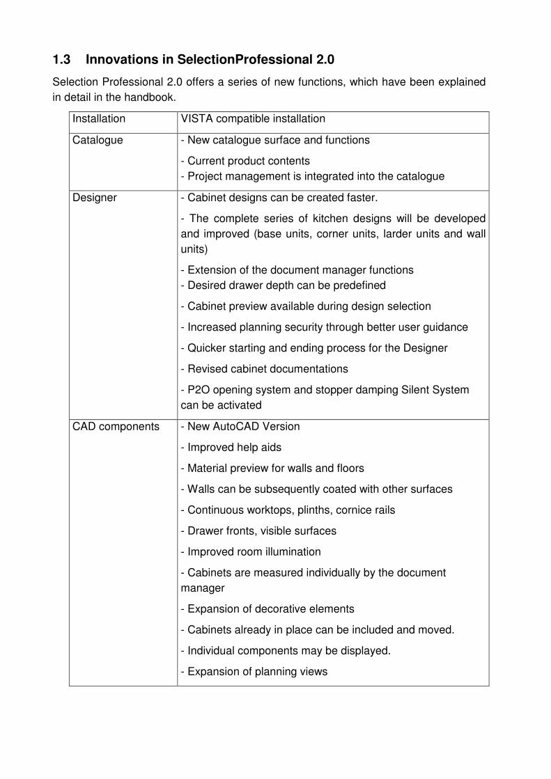
1.3 Innovations in SelectionProfessional 2.0
Selection Professional 2.0 offers a series of new functions, which have been explained
in detail in the handbook.
Installation VISTA compatible installation
Catalogue - New catalogue surface and functions
- Current product contents
- Project management is integrated into the catalogue
Designer - Cabinet designs can be created faster.
- The complete series of kitchen designs will be developed
and improved (base units, corner units, larder units and wall
units)
- Extension of the document manager functions
- Desired drawer depth can be predefined
- Cabinet preview available during design selection
- Increased planning security through better user guidance
- Quicker starting and ending process for the Designer
- Revised cabinet documentations
- P2O opening system and stopper damping Silent System
can be activated
CAD components - New AutoCAD Version
- Improved help aids
- Material preview for walls and floors
- Walls can be subsequently coated with other surfaces
- Continuous worktops, plinths, cornice rails
- Drawer fronts, visible surfaces
- Improved room illumination
- Cabinets are measured individually by the document
manager
- Expansion of decorative elements
- Cabinets already in place can be included and moved.
- Individual components may be displayed.
- Expansion of planning views

Handbook SelectionProfessional
SelectionProf_Handbook_EN.pdf 9 / 143
1.4 Help / Infoline
Selection Professional provides you with an extensive help system:
1. Manual
In addition to the main handbook, further handbooks on special topics are also
available.
SelectionProf_Installation_EN.PDF
SelectionProf_Catalogue_EN.PDF
SelectionProf_Training exercises_EN.PDF
SelectionProf_Library_EN.PDF
The handbooks are present in the Selection/info/help/language folder.
You can also get started from the Assistant construction details of the designer or
through with the symbol Help.
2. On-line help in the programme
You can select to get help on any particular part of the programme you happen to
be working in. The Assistants provide additional information as well as a "Help" link.
You will also find further information in the programme menu under "Help".
3.Internet
Log on to www.selection-professional.com for all the latest information, news, tips &
tricks and fast answers to FAQs about Selection Professional.
In addition, you will be informed about the latest updates. The manuals and further PDF
documentation are constantly updated here as well. This is where you will also find the
links for downloading the Internet Explorer or Adobe Acrobat programmes you will need.
4. Info line
Hettich also operates an info line to provide help with any unanswered questions you
may have.
Tel.: +44 (0)160 - 872 95 52
Fax: +44 (0)161 - 848 76 05
E-mail: [email protected]
Internet: www.selection-professional.com

1.5 Installation / Activation
The program should be activated after installation. Activation should be carried out
within 30 days. After that the designer component can no longer be used. However the
registration can be implemented after 30 days. A detailed introduction for installation
and activation is available in the help document “SelectionProf_Installation_EN.PDF “.
2. First steps
2.1 Starting SelectionProfessional
The programme can be started from the desktop icon or by selecting
Start/Programmes/Selection/Selection Professional within the programme.
The Selection Professional portal opens once the programme has been started.
Selection Professional is divided into several parts:
1) Start design component Designer & Hettich catalogue
2) Start design component Designer
3) Start Hettich catalogue
2.2 Programme components
1) Start design component Designer & Hettich catalogue
With this option, the designer, the CAD component and the catalogue in
background would be started. This is immediately available by accessing
favourites in the catalogue and does not need to be started anymore.
2) Start design component Designer
Here only the Designer + CAD component would be started. If the catalogue is
required only for a favourite query then it can be started later. The advantage lies
in the quick start and lesser consumption of the required system resources.
3) Start Hettich catalogue
Here only the Hettich catalogue would be started.
Please do not close any of these points while working with the program.

Handbook SelectionProfessional
SelectionProf_Handbook_EN.pdf 11 / 143
2.3 Example design
2.3.1 Starting and selecting a design
Once you have started the Designer from the start portal, you will see "Design
Assistant". The "New construction" option takes us to the construction selection window.
The basic types of the furniture you are going to design are shown in the construction
selection window. Selecting a "+" sign opens an option, "-" closes it again.
For the example design, let us select a "Standard cabinet / Single cabinet / Overlay".
The relevant dialog is opened at the bottom right by selecting "Carcase size".

Change the height to 820 (figures are always in mm, the unit of measure does not need
to be entered), width to 900.
Entered values do not have to be saved or confirmed by pressing Enter. You can switch
between the different input fields using the mouse.
Now select the "Bottom shelf" and enter the "120" in the "Height offset" field. This raises
the base by 120mm, with the sides continuing through to the floor.
The forward button takes you to the carcase division window.
2.3.2 Carcase division
The cabinet is displayed from the front and from the side. The Assistant shows all parts
that can be incorporated into the cabinet.

Handbook SelectionProfessional
SelectionProf_Handbook_EN.pdf 13 / 143
Insert centre panel
For the example design, let us use the "Insert centre panel" function to add the centre
panel. A new dialogue window opens at the bottom right.
The position of the centre panel is defined in the "Division" field. The position is set to
600mm from the left by entering "600mm:1". The 600mm relate to the clear internal
width. The mm must always be included for divisioning. Division is the only field that
demands the "mm" unit of measure. The "1" represents a ratio and indicates the
remaining available space. Details on using the division function are also provided in
the section headed "Front and component divisioning".
The green ticks are used for confirming the
entries you make and for inserting the centre
panel.
Setting zones
As the next step, we are going to add a shelf. A so-called "Zone"
must be activated so that the system knows which side to fit the
shelf on. This is done by clicking the mouse inside the
appropriate section of the cabinet. As we are going to put a shelf
in the left-hand section / zone, this is the zone you must click the
mouse in. It is highlighted in green.
Details on the subject of zones and parts are provided in the
section headed "Zones and parts".

Inserting shelves
Select the "Insert shelf" function from the Assistant. A new dialog
window now opens at the bottom right. We are now going to
space three shelves apart at equal distances throughout the
zone. To do this, enter or select the number "3" from the menu.
This corresponds to a spacing of "1:1:1:1".
As before, the entry is confirmed with the green tick.
Inserting doors
As the next step, we are going to add the doors. To do this, you
must once again activate the left-hand zone with the mouse so
that it is displayed in green. Select "Insert doors" from the
Assistant. The dialogue window opens. Select "Standard door"
as the door type. Select the "+" sign to obtain further details on
this door type. Two further options are opened: "Division" and
"Hinge". In "Division", select "Double door" from the
"Construction type" field. Options can be selected by clicking the
arrow to the right of the field. Finally, confirm your entries with
the green tick.
Inserting drawers
Now click on the right-hand zone, which is still blank, to activate
it. This zone is then displayed in green. From the Assistant,
select "Insert drawers".
The relevant dialogue opens. You can choose from a variety of
drawer types. In our example, we are going to select a "Wood-
box with internal drawer". This drawer is to be mounted on a
"Quadro runner". This option must, therefore, be selected too.
Use the "+" sign to select the "Division" option. Select three for
"Number". The fronts are distributed evenly throughout the
height. Entries are confirmed with the green tick.
Handbook SelectionProfessional
SelectionProf_Handbook_EN.pdf 15 / 143
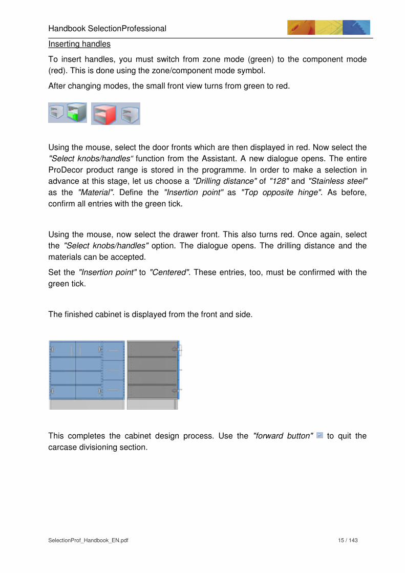
Inserting handles
To insert handles, you must switch from zone mode (green) to the component mode
(red). This is done using the zone/component mode symbol.
After changing modes, the small front view turns from green to red.
Using the mouse, select the door fronts which are then displayed in red. Now select the
"Select knobs/handles“ function from the Assistant. A new dialogue opens. The entire
ProDecor product range is stored in the programme. In order to make a selection in
advance at this stage, let us choose a "Drilling distance" of "128" and "Stainless steel"
as the "Material". Define the "Insertion point" as "Top opposite hinge". As before,
confirm all entries with the green tick.
Using the mouse, now select the drawer front. This also turns red. Once again, select
the "Select knobs/handles" option. The dialogue opens. The drilling distance and the
materials can be accepted.
Set the "Insertion point" to "Centered". These entries, too, must be confirmed with the
green tick.
The finished cabinet is displayed from the front and side.
This completes the cabinet design process. Use the "forward button" to quit the
carcase divisioning section.
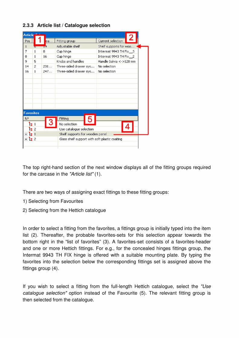
2.3.3 Article list / Catalogue selection
The top right-hand section of the next window displays all of the fitting groups required
for the carcase in the "Article list" (1).
There are two ways of assigning exact fittings to these fitting groups:
1) Selecting from Favourites
2) Selecting from the Hettich catalogue
In order to select a fitting from the favorites, a fittings group is initially typed into the item
list (2). Thereafter, the probable favorites-sets for this selection appear towards the
bottom right in the “list of favorites” (3). A favorites-set consists of a favorites-header
and one or more Hettich fittings. For e.g., for the concealed hinges fittings group, the
Intermat 9943 TH FIX hinge is offered with a suitable mounting plate. By typing the
favorites into the selection below the corresponding fittings set is assigned above the
fittings group (4).
If you wish to select a fitting from the full-length Hettich catalogue, select the "Use
catalogue selection" option instead of the Favourite (5). The relevant fitting group is
then selected from the catalogue.

Handbook SelectionProfessional
SelectionProf_Handbook_EN.pdf 17 / 143
For example, the following selection is carried out:
Pos. 1 Cup hinge > Favourite > Intermat 9943 TH Fix
Pos. 2 Cup hinge > Favourite > Intermat 9943 TH Fix
Pos. 3 Knobs and handles > Use catalogue
Pos. 8 Quadro runner > Favourite > Quadro V6/550
Pos. 11 Adjustable shelf > Favourite > Compartment shelf support for wooden
shelves
To position the fittings group “handles and knobs“on “Use catalogue selection“, the
entry should be initially selected with the help of the mouse in the item list.
Subsequently the entry “Use catalogue selection“ is selected in favorites.
The catalgue start is executed with the green check mark . The programme opens
the electronic Hettich catalogue and searches for suitable products under the “handles
and knobs“fittings group.
The catalogue now displays all handles that match the previously defined properties
(material + drilling distance).

Three symbols appear in front of the list:
Select accessories
Transfer to CAD
Detailed information
Select accessories
The accessories that are available for the main article are selected by clicking the
accessories symbol. A list of accessories shows all possible accessory types. If an
accessory is an article that is essential for the design, a red exclamation mark is set in
front of the relevant group. If you don't select an essential accessory article, the
programme automatically prompts you to do so.
Transfer to CAD
If you wish to select an article from the product list for the design, select the CAD
symbol. Add the relevant article to the article list.
Detailed information
If you require additional information on the product, click the "Detailed information"
button to retrieve further details. From the detailed overview, you can also display the
accessory or transfer the article to the Designer.
In our example, we are going to select any random handle and click the Designer
transfer button.
The programme automatically adds the handle to the article selection list. For the next
item of furniture you design, there is no need to select the handle again but retrieve it
directly from Favourites.
The article list changes its colour from black to green. This completes the article
selection process. The item selection is thus complete and the entry of the item list is
fixed. If the selection for this entry is changed, it has to be selected in the item list using
the right mouse click. At the end it can again be released using “change”.
One can leave the item selection using the forward arrow.

Handbook SelectionProfessional
SelectionProf_Handbook_EN.pdf 19 / 143
The finished cabinet is displayed in 3D. You can now carry out a number of actions on
the cabinet.
2.3.4 AutoCAD display
The CAD / Roomplan function in the Assistant allows you to switch to the AutoCAD
module. The cabinet is displayed in a wire grid 3D perspective. Component
dimensioning is the most important function in the AutoCAD section of the programme.
Let us dimension the left outer side of the carcase automatically. To do this, change to
the top view using the symbol.
This is opened by clicking the "Dimension part" symbol (left). The cursor changes
into a rectangle. Using the rectangular cursor, now select the outer side. It is important
to select precisely the line that represents the outer side.
The component is automatically displayed with dimensions. It can be printed out or
saved in the 2D view.

The "Dimension part" symbol enables you to perform further dimensioning. Quit the
dimensioning mode by clicking the "Reverse dimensioning" symbol (right).
Click the "Switch to Designer“ button in the Assistant to quit the AutoCAD part of the
programme and return to the Designer in the 3D view. Nothing needs to be saved in the
AutoCAD part as this is all controlled through the Designer part.

Handbook SelectionProfessional
SelectionProf_Handbook_EN.pdf 21 / 143
3. Designer - Functional description
3.1 Screen layout
The Designer screen is divided into several sections that are repeated at all design
stages.
1) Progress bar
The Designer is divided into 4 sections that run through in succession.
Selecting a construction
Carcase division
Article list / Catalogue selection
3D display
The section activated is shown by a red line below the relevant image.

2) Assistant
The Assistants guide you through the programme and display the range of functions
that are available. They also provide helpful tips on the application concerned. You can
get additional information by selecting "Help".
Upload standard settings
Uploads standard Designer settings. Modified values are reset to original values again.
Open
Opens an existing design. You are given the possibility of saving the active design.
CAD/Roomplan
This option is used for opening the AutoCAD part of the programme. This must be done, for example, to dimension the design or to start Roomplan.
All details of the AutoCAD functions are explained later on in the manual.
End Designer
Closes the Designer as well as the AutoCAD and AutoCAD Renderer parts of the programme. Alternatively, you can also close the programme by selecting the "File/Exit" menu options. The programme should always be closed from the Designer and not from other parts, such as the AutoCAD part.
Help
Retrieves help on the Assistant. The handbooks can be started from the overview.
3) Section change
The forward button can be used to change from one segment to the next. Use the
backward button to return to the previous view. This enables to move backwards and
forwards at any time and is particularly useful, for instance, if you wish to make an
alteration.
4) File informations
Profile: Shows the current profile name.
Name: Name of the cabinet if saved.

Handbook SelectionProfessional
SelectionProf_Handbook_EN.pdf 23 / 143
5) Menu bar
File
New: Creates a new design.
Open: Opens a cabinet that has already been designed.
Save: Saves a cabinet currently being designed. This function is only available
once you reach the Carcase division part.
Delete: This is where you can delete saved cabinets.
Import: This can be used to make cabinets available to other Selection
Professional users or save a cabinet to an external data medium (floppy
disk, memory stick etc.).
Export: Reads cabinet designs in from other Selection Professional users or loads
cabinet designs from an external data medium.
End: Exits the Designer and Selection CAD.
Profile
For some furniture designs it is often necessary to select specific settings. For kitchen
base units, for example, it is generally possible to select 16 panel thicknesses, or
always use grooved rear panels. All settings (e.g. cabinet height, width, base panel
thickness, backset dimensions etc.) that are capable of being altered in the construction
selection window can be saved under custom profiles.
Load: Loads an existing profile
Save: Saves a profile. All changes made in the construction selection window,
from the standard cabinet to custom designs, are saved.
Delete: Deletes an existing profile
Help
Retrieves help on the Assistant currently being used.

3.2 Screen layout cabinet partitioning
1) Preview image
The preview image displays the cabinet in 2D in front and lateral view.
2) Action buttons
Front view
Top view
Changes to 3D mode
Changes to component mode
Changes to zonal mode
3) Assistant
Different components and fittings for the cabinet partitioning can be selected from the
Assistant.

Handbook SelectionProfessional
SelectionProf_Handbook_EN.pdf 25 / 143
3.3 Screen layout item lists
The designs of the suitable fittings are allocated in the item lists. They may be selected
from the Hettich catalogue or from favorites.

3.4 Screen layout completed design
1) Window functions
The completed cabinet design is displayed in the window. In addition, different mouse
functions are available.
Left mouse button Turns cabinet
To do this, keep the left mouse button pressed and
turn the mouse in the chosen direction.
Right mouse button Magnifies / reduces the cabinet image
Keep right mouse button pressed and move mouse
away from you or towards you. Moving away from
you reduces the image, moving towards you
magnifies it.
Left + right mouse button Shifts cabinet
Keep right+left mouse button pressed simultaneously
shift in the chosen direction.

Handbook SelectionProfessional
SelectionProf_Handbook_EN.pdf 27 / 143
The functions of the mouse can also be permanently assigned to the left mouse button.
To do this, select one of the three symbols.
Left mouse button to reduce / magnify cabinet image
Left mouse button to turn cabinet
Left mouse button to shift cabinet
To cancel the function, all you have to do is re-select it. Now it is deactivated again.
2) Action buttons
Front view
Side view
Top view
Set standard (useful if everything has been adjusted)
Concealed cabinet display
Semi-transparent cabinet display
Wire grid model
3) Assistant
New construction
Starts a new design. There are two ways of saving the active design.
Save
Saves the active design. You can select an existing directory or create a new one.

Change functions
Alterations can be made to the cabinet designed in Selection Professional. This is done
using the following functions:
- Change dimensions (e.g. height, panel thickness etc.)
- Change divisioning (e.g. add shelves, change doors etc.)
- Change fittings (e.g. change handle selected, select another hinge type etc.).
You can find details on the different ways of making alterations in the section headed
"Altering designs".
Hesse Module
The cabinet can be displayed in different surfaces with the help of the Hesse Module.
In addition, it is possible to switch to display options with the help of the “Output“ tab.
3.5 Zone and components
3.5.1 Example of how to select zones
Selecting zones and components is an important function within the carcase divisioning
section. The cabinet displayed below is to be divided into different sections.
So far, the cabinet has had three evenly spaced centre panels. We are now going to
add a construction shelf to all four resultant zones.
Handbook SelectionProfessional
SelectionProf_Handbook_EN.pdf 29 / 143
If you wish to activate several zones, they must be selected in succession. If you have
selected the wrong zone, it can be deactivated by selecting it a second time.
If several zones were addressed and only one needs to be activated, a double click in
the desired zone will deactivate all the other zones again.
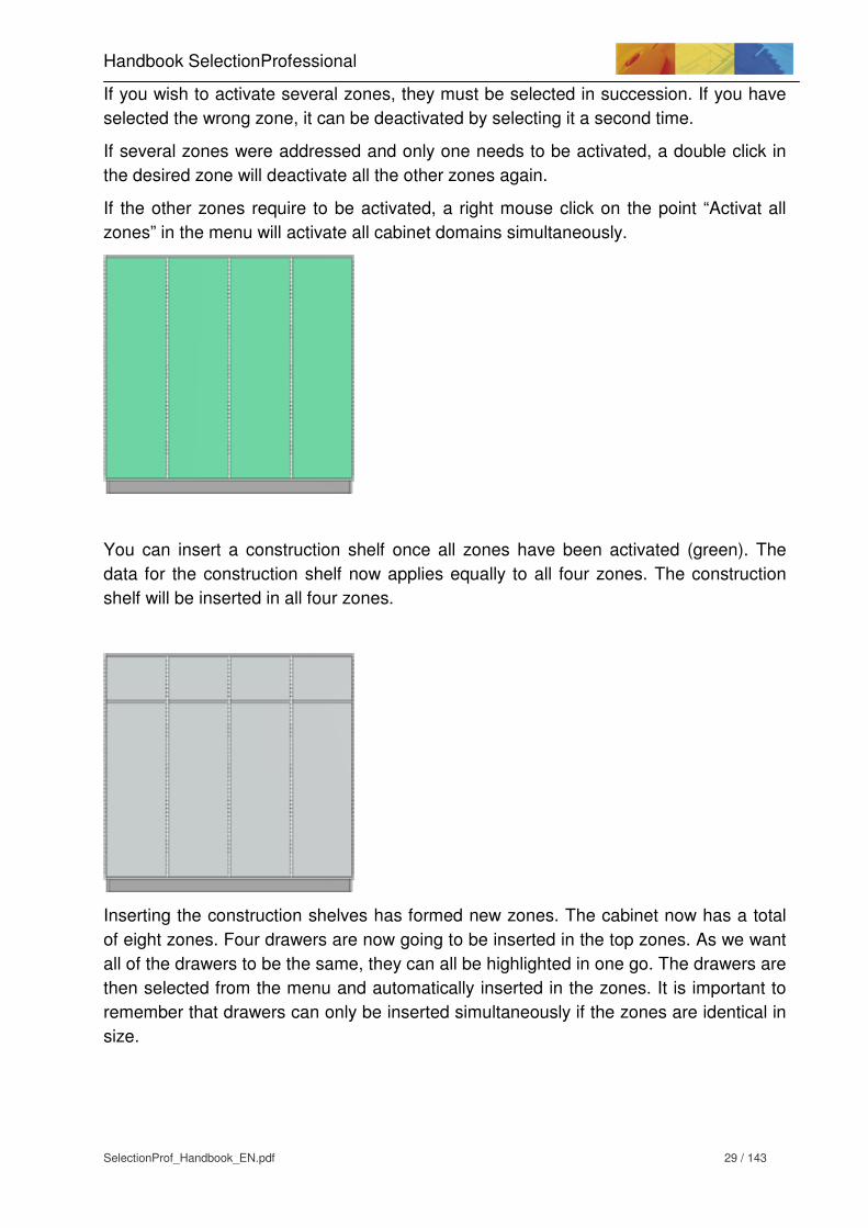
If the other zones require to be activated, a right mouse click on the point “Activat all
zones” in the menu will activate all cabinet domains simultaneously.
You can insert a construction shelf once all zones have been activated (green). The
data for the construction shelf now applies equally to all four zones. The construction
shelf will be inserted in all four zones.
Inserting the construction shelves has formed new zones. The cabinet now has a total
of eight zones. Four drawers are now going to be inserted in the top zones. As we want
all of the drawers to be the same, they can all be highlighted in one go. The drawers are
then selected from the menu and automatically inserted in the zones. It is important to
remember that drawers can only be inserted simultaneously if the zones are identical in
size.

Loose shelves are now going to be added across all four bottom zones. To do this, you
must once again activate all four zones and select the shelves from the Assistant.
Unlike construction shelves, loose shelves do not form zones.
Now we are going to insert doors in the right and left-hand zone. As this requires the
use of a left-hinged and a right-hinged door, they must be selected separately.
Highlight the zones individually and insert the appropriate door in each. Let us now
insert a double door in the middle. To do this, both zones can be selected
simultaneously. After selecting the door function, a double door will be inserted
automatically. If you activate several zones, the programme automatically tries to insert
one door across all zones. If, added together, the zones are wider than 600mm, a
double door will be inserted automatically.

Handbook SelectionProfessional
SelectionProf_Handbook_EN.pdf 31 / 143
The cabinet is now equipped with all elements. This is the point at which to select the
handles for the fronts. To do this, you must click the "Zone mode/Component mode"
to switch to the component mode (red). First, select all drawer fronts so that all
four are displayed in red. Using the "Select/change knobs/handles" function, assign a
handle to all drawers.
Now highlighted in red, all drawers are fitted with the handles. In the "Insertion point –
Top opposite hinge" handle setting, the programme automatically places the handles in
the correct position.
3.5.2 Changing, deleting, hiding parts
Any mistake that is made while configuring the cabinet can be corrected at a later stage.
You can also subsequently change any part already inserted.
Example of how to change handles
In our example, we want to relocate the handles from a centred position to the upper
mid-point. To do this, switch to the component mode (red) and select all drawer fronts.
Now press the right mouse button and select the "Change knob/handle" option. The
handle dialogue opens, allowing you to re-position the insertion point. You could, of
course, also have changed other options.
Example of how to change the side on which a door is hinged
The right-hand door is to be hinged on the left side. To do this, select the door in the
component mode and press the right mouse button. From the dialog, select the
"Change part" option. The door dialogue opens, allowing you to change the design to
"Hinge left".

Example of how to delete a shelf
To delete a component, it must be selected in the component mode. However, you
cannot select the shelf directly because the door is in front of it. By pressing the right
mouse button, select the "Show front panel" option. After removing the tick, the fronts
will be hidden. They are not deleted, but merely no longer visible. Now, in the
component mode, you can select the shelf you want to delete. Remember here that if
several shelves were inserted together, they will also be deleted together. This is
always the case for elements that are inserted simultaneously.
Summary
The zone selection function (green) is used for selecting cabinet sections for equipping
with doors, drawers, shelves etc.
Component selection function (red) is used for changing or deleting components
already inserted. It is also required for selecting handles.
In the component mode, the right mouse button can be used to perform different
functions:
Activate zones Changes over to zone selection. Performs the same
action as the zone/component selection button
Delete part Deletes the component selected with the mouse
Change part Opens the dialogue for changing the component
concerned
Change
knob/handle
Opens the knob/handle dialogue for making the relevant
changes
Activate all
components
Activates all components in the cabinet
Activate all fronts Activates all fronts on the cabinet
Deactivate all
components
Deactivates all previously activated components in the
cabinet
Show front panel No fronts are shown once the tick is removed.

Handbook SelectionProfessional
SelectionProf_Handbook_EN.pdf 33 / 143
The right mouse button is equipped with other functions in the zone mode:
Activate component
selection
Switch to component selection. Analogous to the
Zones/Components button.
Activate all zones Activates all cabinet domains.
Deactivate all
zones
Deactivates all the activated cabinet domains
3.6 Front and component divisioning
A carcase needs to be divided into sections or ratios in many different parts. The drawer
front, for example, must be divided up into different height ratios. Centre panels must be
spaced apart by internal widths. The hole lines are arranged in relation to depth and
height. Cup drillings are positioned in the front.
Selection provides one single function for all of these operations: Division. This is used
for performing all the necessary functions.
Divisioning works with exact dimensions or ratios. These two options can also be
combined.
"1:1:1" is a division that splits a section into two equal parts.
"200mm:200mm:100mm" divides a 500mm section into parts at the distances specified.
„200mm:1:1“ divides a part in the lower or left section at exactly 200mm, the remainder
into two equal halves.
With this, partitions are always undertaken from left to right (e.g. centre panels), bottom
to top (e.g. drawers) or from front to rear (e.g. hole lines).
Below, you will find a number of divisioning examples. They may also be applied to
divisioning in other application areas.

Hole-line division
A division can be used to position the hole line in terms of depth.
Default setting: 37mm:1:37mm
The first hole line now starts at 37mm from the front edge of the cabinet side, the
second hole line starts at 37mm from the interior of the rear panel.
The inclusion of ":1:" shows that the depth of the cabinet is unimportant. Even if the
cabinet depth were to change, the dimensions of 37mm from the front and 37mm from
the back stay as they are. The ":1:" may be regarded as a variable placeholder.
If you wish to insert a third hole line exactly mid-way between the other two hole lines,
enter the following division:
"37mm:1:1:37mm"
Each „:“ is present for a hole line.
Top panel / connector divisioning
Connectors can be set for the top and bottom panel.
The standard setting for "Connector division" is "37mm:1:37mm". This shows that the
connection is located exactly on the hole line. By changing the divisioning, you can, for
example, insert additional connectors.
Centre panel divisioning
Through the "Division", a centre panel divides a selected carcase zone from left to right.
A 1:1:1:1 divisioning inserts three centre
panels. The internal widths between individual
panels are identical.

Handbook SelectionProfessional
SelectionProf_Handbook_EN.pdf 35 / 143
Die Aufteilung 300mm:1:1:300mm fügt
ebenfalls drei Mittelseiten ein. Die erste und
die letzte Zonen haben eine lichte Breite von
300mm. Both inner zones are automatically
divided equally.
Construction shelf divisioning
Construction shelves are divided from bottom to top. Once inserted, they form new
zones. The reference point for a construction shelf is therefore the bottom shelf or a
construction shelf that has already been inserted. For the construction panels the inside
height is defined between the bottom panels.
A 300mm:200mm:1 divisioning inserts two
construction shelves. The inside distance of
the bottom construction panel to bottom panel
is 300mm and the inside distance between the
bottom construction panel and the top
construction panel is 200mm. The inside
distance between the top construction panel
and the top panel is calculated from the
remainder.

Drawer divisioning
Drawers are divided from bottom to top. Divisioning relates to the dimensions of the
front.
1:1:1
2:1:1
300mm:200mm:1

Handbook SelectionProfessional
SelectionProf_Handbook_EN.pdf 37 / 143
3.7 Item lists and favorites lists
After the definition and partitioning of the cabinet is complete, the fittings should be
allocated. This is carried out in the item list/favorites list section.
In this section the preassembled cabinet is examined on the basis of the available
fittings group. Subsequently the potential fittings can be allocated through the favorites
list or the catalogue selection of the corresponding fittings group.
It is sub divided into item list (1), favorites list (2) and front view of the cabinet (3).
3.7.1 Item list
All fittings group available in the cabinet are present in the item list (1). In the sample
cabinet three complete drawers are fitted with one handle each. This leads to the
formation of 3 fittings groups, one group “Handles and knobs“and 2 groups “Three sided
drawer system”.
If fittings groups can be merged together, based on their similarity, then they are
grouped, e.g. the fittings group „Handles and knobs“. For preassembled drawers the top
drawer is considerably lower than the remaining two, which is why only the two lower
drawers are grouped. The top drawer receives its individual fittings group. In contrast to
both the lower drawers, no front pullouts can be fitted into the top drawer.
To switch off the grouping the right mouse button is clicked anywhere in the item list.
The menu which is opened as a result displays the entry “group positioning” with a
check mark, which means that the grouping is active. The grouping is switched off by
clicking on the entry and all fittings groups in the item list are shown individually. To
reactivate the grouping, the entry “group positioning” is clicked again. By switching off
the grouping, different fittings can be allocated to the individual fittings groups.
If a fittings group is clicked on in the item list, the corresponding components in the front
view of the cabinet (3) are highlighted in red and the first favorites set is automatically
selected. To assign the desired fitting from catalogue selection the coreesponding
fittings group should be placed on “Use catalogue selection”. Subsequently the
catalogue selection can be started with the green check mark .
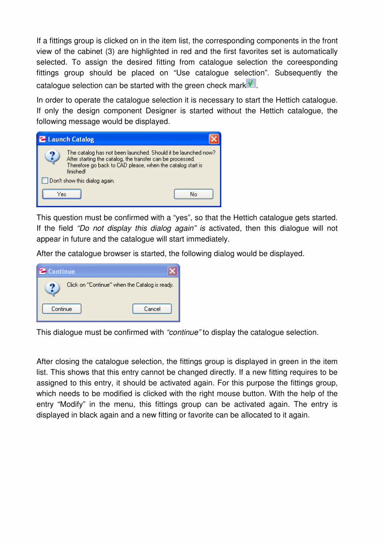
In order to operate the catalogue selection it is necessary to start the Hettich catalogue.
If only the design component Designer is started without the Hettich catalogue, the
following message would be displayed.
This question must be confirmed with a “yes”, so that the Hettich catalogue gets started.
If the field “Do not display this dialog again” is activated, then this dialogue will not
appear in future and the catalogue will start immediately.
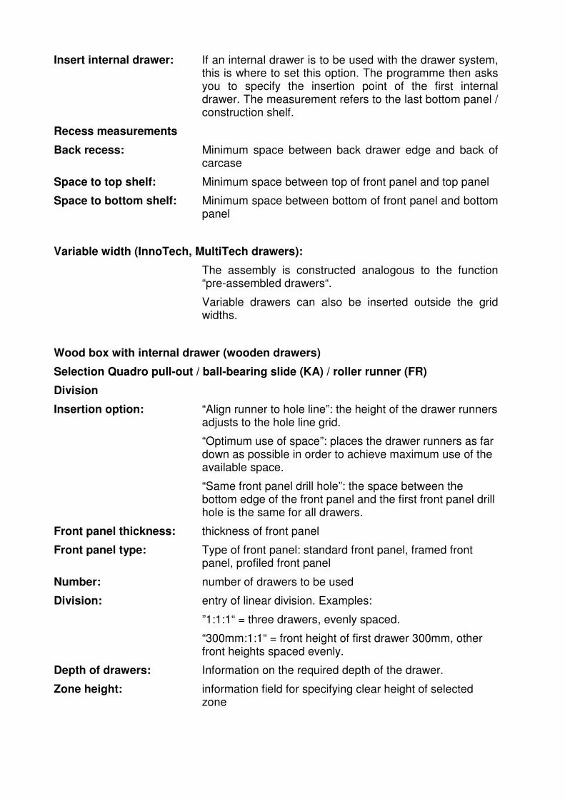
After the catalogue browser is started, the following dialog would be displayed.
This dialogue must be confirmed with “continue” to display the catalogue selection.
After closing the catalogue selection, the fittings group is displayed in green in the item
list. This shows that this entry cannot be changed directly. If a new fitting requires to be
assigned to this entry, it should be activated again. For this purpose the fittings group,
which needs to be modified is clicked with the right mouse button. With the help of the
entry “Modify” in the menu, this fittings group can be activated again. The entry is
displayed in black again and a new fitting or favorite can be allocated to it again.

Handbook SelectionProfessional
SelectionProf_Handbook_EN.pdf 39 / 143
3.7.2 The favorite list
All fittings, which were selected in the previous catalogue selection, are saved in
favorite sets in the favorite list (2). A favorite set consists of a header and one or more
fittings, which were selected during the respective catalogue selection.
If a fittings group is clicked in the item list, then all possible favorite sets for this
positioning are displayed in the favorites list and the first favorite set is automatically
assigned to the fittings group. If any other favorites set should be assigned to the fittings
group, it should be clicked in the favorites list.
In order to view the contents in the individual favorite sets, the entry can be expanded
with the help of the plus symbol. A favorite set cannot be modified. If a fitting does not
match with a set, then a new favorites set can be selected from the catalogue selection.
A favorites set can only be deleted or renamed. However this functions only if the
fittings group in the item list is not displayed in green. The fittings group should first be
activated with the “Modify“option in the menu. If the fittings group and the favorites are
displayed in black, the individual favorites sets can be deleted or renamed. For this
purpose the corresponding entry is clisked upon with the right mouse button and the
desired point is selected in the menu. If the favorites set should be renamed, then only
the header of the set is changed.
3.8 Export
One can arrive at the display options of Selection Professional through the tab “display“.

3.8.1 Bill of items – wood
The wood – item list contains all the required components of a cabinet.
Edit
Displays the Bill of Materials- Wood. Remarks can be added. The Bill of Materials –
Wood can be subsequently printed or saved as TXT/CSV file.
Prints the bill of items.
Save
Saves the bill of items as a TXT/CSV file.
3.8.2 Hettich order list
The Hettich order list shows all of the fittings that are required for the cabinet and
selected from Favourites or the catalogue selection window.
Edit
Presents the Hettich fittings list. Remarks can be added. The Bill of Materials – Wood
be subsequently printed or saved as a TXT/CSV File.

Handbook SelectionProfessional
SelectionProf_Handbook_EN.pdf 41 / 143
Prints the bill of items.
Save
Saves the bill of items as a TXT/CSV file.
3.8.3 Document Manager
The document manager provides a summary of all information relevant to production. A
more detailed explanation can be found in Chapter 5 “Document manager“.
3.8.4 Hesse order list
This list calculates and displays the quantities of lacquer that are required.
All exports and their functions are described in greater detail in "Designer export
formats".
3.9 Loading, saving, cabinet library
Cabinets designed in Selection Professional can be saved through the Assistants or the
programme menu (File /Save / Load). Once saved, they can be re-loaded at any time
and edited. Saved cabinets can be filed in folders. This allows you to create your own
personal cabinet library.
An extensive collection of designs has already been filed for kitchens and offices.
An exact overview of the designs is available in the folder Selection/help/language „
SelectionProf_Library_EN.PDF “

3.10 Hesse Module
Use the Hesse Module to display the finished cupboard and the room situations you
have created in photographic quality.
Start the Hesse Module
Once you have drawn a carcase, you can use the “Hesse Module” link to start designing
the surface finish. You will find this link in the 3D view of the Designer in the
“Construction” Assistant, in the “CAD” CAD Assistant or in the “Roomplan” CAD
Assistant.
Choosing a colour / Allocating a lacquer
You will see the window with the colour choices. First select a carrier material. Once
you have done so, you need to choose the colour or surface finish.
Click on the right button to choose the colour. .
This displays a new window. Use the arrow to make your colour choice, and then use
the green arrow to confirm.
When you have chosen your colour, click on the button in the window for choosing the
surface finish, where you can select the lacquer system. .
When you have worked through and confirmed all the parameters, the cupboard will be
created with your chosen surface finishes.

Handbook SelectionProfessional
SelectionProf_Handbook_EN.pdf 43 / 143
3.11 Functions in the standard cabinet, sliding and folding, special
designs sections
3.11.1 “Insert centre panels" function
Inserts one or more panels in one or more carcase zones. To do this, the desired zone
in the carcase must first be selected with the mouse.
Number: number of centre panels
Division: enter the linear division. Examples:
“1:1:1” = two centre panels, evenly spaced.
“400mm:1:1” = two centre panels, clear internal width of
first zone 400mm
Zone width: information field for specifying clear internal width of
selected zone
Thickness: thickness of centre panels
Front recess: Reference for the front recess. Possible values are “Part
and zone” and “Part”.
Reference “Part and zone”: When recessing the centre panels, the zone is also
recessed.
Reference “Part”: When inserting the centre panels the zone is not included.
Backset value: measurement for the front recess of the centre panel
Back recess / Backset value:
Same function as Front recess
Function “Use connectors”.
Activate or deactivate the use of centre panel connectors
Division: division of the centre panel connectors in the form of linear
division
Insertion point: point where the centre panel connectors are inserted
Function “Use wooden dowel“:
Activation or deactivation of the use of the centre panel-
wooden dowel
Division: Partitioning the centre panel-wooden dowel in the form of
linear division

3.11.2 “Insert construction shelves" function
Inserts one or more construction shelves in one or more carcase zones. To do this, the
desired zone in the carcase must first be selected with the mouse.
Number: number of centre panels
Division: enter the linear division. Examples:
“1:1:1:1” = three construction shelves, evenly spaced.
“300mm:300 mm” = three construction shelves,
300 mm apart
Zone height: information field for specifying clear height of selected zone
Thickness: thickness of construction shelves
Inside depth: Info-field for the inside height of the selected zone
Front recess: Reference for the front recess. Possible values are “Part and zone” and “Part”.
Reference “Part and zone”: when inserting the construction shelf, the zone is also recessed.
Reference “Part”: when inserting the construction shelf the zone is not recessed.
Backset value:: measurement for the front recess of the construction shelf
Use connectors: Activate or deactivate the use of connectors for the construction shelves
Fucktion “Use wooden dowel“:
Activation or deactivation of the centre panel-wooden dowel
Adjust panel to hole line: Construction shelf spacing is adjusted to the line of holes.
Division: Partitioning the centre panel-wooden dowel in the form of linear division
Insertion point: Insertion point of the construction panel - wooden dowel
Division: Positioning of the connectors for construction shelves in the form of linear division. If “Adjust panel to hole line” is activated, the positioning of connectors for the construction shelves cannot be changed. It is then matched to the position of the hole line.
Insertion point: point where the connectors for the construction shelves are inserted

Handbook SelectionProfessional
SelectionProf_Handbook_EN.pdf 45 / 143
3.11.3 “Insert shelves" function”
This function is structured in the same way as the “Insert construction shelf” function.
Loose shelves have a standard recess of 15mm and cannot be used to recess zones.
The options “Use connector“and “Align drawer bottom to hole line“are activated by
default.
3.11.4 “Insert drawers" function“
This Assistant inserts one or more InnoTech drawers, wood box with internal drawers,
pull-out shelves or front panels in one or more carcase zones. The desired zone in the
carcase must first be selected with the mouse. The desired drawer runners are selected
from the product tree.
Drawer system
Complete drawer (e.g. InnoTech complete drawers)
Division
Insertion option “Align runner to hole line”: the height of the drawer runners adjusts to the hole line grid.
“Optimum use of space”: places the drawer runners as far down as possible in order to achieve maximum use of the available space.
“Same front panel drill hole”:
the space between the bottom edge of the front panel and the first front panel drill hole is the same for all drawers.
Front panel thickness: thickness of front panel
Drawer front type: Type of drawer front: Standard drawer front, frame drawer front, profile drawer front
Number: number of drawers to be used
Division: entry of linear division. Examples:
”1:1:1“ = three drawers, evenly spaced.
„300mm:1:1“ = front height of the lowest drawer 300 mm, remaining front height is divided equally.
Depth of drawer: Pre-selection of the desired nominal length of the drawer.
Zone height: information field for specifying clear height of selected zone
Inside depth: Info-field for the inside depth of the selected zone
Insert internal drawer: If an internal drawer is to be used with the drawer system, this is where to set this option. The programme then asks you to specify the insertion point of the first internal drawer. The measurement refers to the last bottom panel / construction shelf.
Recess measurements
Back recess: Minimum space between back drawer edge and back of carcase
Space to top shelf: Minimum space between top of front panel and top panel
Space to bottom shelf: Minimum space between bottom of front panel and bottom panel
Variable width (InnoTech, MultiTech drawers):
The assembly is constructed analogous to the function “pre-assembled drawers“.
Variable drawers can also be inserted outside the grid widths.
Wood box with internal drawer (wooden drawers)
Selection Quadro pull-out / ball-bearing slide (KA) / roller runner (FR)
Division
Insertion option: “Align runner to hole line”: the height of the drawer runners adjusts to the hole line grid.
“Optimum use of space”: places the drawer runners as far down as possible in order to achieve maximum use of the available space.
“Same front panel drill hole”: the space between the bottom edge of the front panel and the first front panel drill hole is the same for all drawers.
Front panel thickness: thickness of front panel
Front panel type: Type of front panel: standard front panel, framed front panel, profiled front panel
Number: number of drawers to be used
Division: entry of linear division. Examples:
”1:1:1“ = three drawers, evenly spaced.
“300mm:1:1“ = front height of first drawer 300mm, other front heights spaced evenly.
Depth of drawers: Information on the required depth of the drawer.
Zone height: information field for specifying clear height of selected zone
Handbook SelectionProfessional
SelectionProf_Handbook_EN.pdf 47 / 143
Insert internal drawer: If an internal drawer is to be used with the drawer system, this is where to set this option. The programme then asks you to specify the insertion point of the first internal drawer. The measurement refers to the last bottom panel / construction shelf.
Drawer design
Construction drawer front/back:
design option for the front and back panel
„Mitre/mitre“ . Front, rear, side drawers are connected to each other on the mitre.
“inset / inset”: the front and back panel is positioned between the side panel
“none / inset”: the drawer has no front panel; the back panel is positioned between the side panels.
„No / mitre“. The front drawer is to be dispensed with. Rear and side drawers are connected to each other on the mitre.
Thickness: the thickness of the front and back panel
Recess measurement top/front:
the recess measurement from the front panel to the top of the side panels
Recess measurement top/back:
the recess measurement from the back panel to the top of the side panels
Thickness: thickness of side panels
Height: height of side panels
Position of the pullout (for ball bearing slides):
Position of the ball bearing slide on the side drawer; Selection centered: the ball bearing is positioned in the height centered on the side drawer. Selection bottom: The slide position is set on the bottom; the slide position from below the distance from the lower edge of the side drawer to the centre of the ball bearing slide can be specified in the field.

Bottom panel:
Construction drawer front/back/side panel
Design option for drawer bottom
„grooved/grooved/grooved“. Drawer base is grooved into the front, rear and side drawers.
“fitted onto/fitted onto/grooved”: drawer bottom fitted onto front and back panel and into side panel grooves.
“fitted onto/fitted onto/inserted”: drawer bottom fitted onto front and back panel and inserted into side panel
„fitted/fitted/fitted“. Drawer base is fitted into front, rear and side drawers.
Thickness: thickness of drawer bottom
Groove depth: depth of drawer bottom groove in side panel
Rebate depth: insert depth of drawer bottom into side panel
Backset value: backset of bottom panel to bottom edge of side panels
Backset values
Backset value back: minimum distance between the back of the drawer and the back of the carcase
Distance to top panel: minimum distance between panel top and the top panel
Distance to bottom panel: minimum distance between panel bottom and bottom panel
Pull-out shelf
A pull-out shelf is a shelf with a front.
Division / backset values:
The structure and functions are the same as the “Wood-box with internal drawer” function.
Front panel: A front panel is a front that has no drawer or runners behind it.
Division: The structure and functions are the same as the “Wood-box with internal drawer” function.

Handbook SelectionProfessional
SelectionProf_Handbook_EN.pdf 49 / 143
3.11.5 “Insert internal drawers" function
Internal drawers can be inserted behind normal drawer systems. Before an internal
drawer can be inserted, the “Insert internal drawers” option must be selected to set the
drawer.
Then, behind the drawer, you must select the zone (in zone mode) which appears in
green. You can now select the “Insert internal drawers" function.
Drawer system
Assembly type: „Align extension to hole line“: The guider tracks of the internal drawer align themselves along their height to the latching of the hole line.
„Optimal usage of space“: Sets the internal drawer guider tracks as far as possible towards the bottom, in order to achieve maximum usage of space.
Partitioning: „from below“. The internal drawers are positioned in the cabinet zone.
„from the centre“. The internal drawers are positioned at the centre in the cabinet zone.
Number of thrusts: Number of internal drawers
Zone height: Info-field for the inside height of the selected zone
Indent dimensions
Indent dimension rear: Minimal distance of the internal drawer rear edge to cabinet rear panel
Wood-box with internal drawer/ Quadro / ball-bearing slide / roller runner
Most functions are structured in the same way as the “Insert drawers – wood-box with internal drawer" dialogues.
Divisioning is adjusted specifically for the interior drawers.
Division
Front panel thickness: thickness of the internal drawer front panel
Rest of zone-height: information field for specifying remaining height of selected zone
Zone height: information field for specifying clear height of selected zone

Division of interior drawers:
“same front/distance”: front panels are all the same height;
distances between the front panels are all the same.
“variable front/distance”: front panels may differ in height;
distances between the front panels may differ
Number: number of internal drawers
Gap: Intermediate space between front panel and top panel, or
other construction panels
If the number of internal drawers is more than 1, further fields are activated.
Front panel height: l height of the interior drawer front panel
Gap: distance between the front panels of interior drawers

Handbook SelectionProfessional
SelectionProf_Handbook_EN.pdf 51 / 143
3.11.6 “Insert doors" function
This function inserts one or more doors or flaps in one or more carcase zones. To do
so, the desired zone in the carcase must first be selected with the mouse. The desired
door types may be selected from the product tree.
Side hung doors
Standard door
Division
Align hinge to hole line: Aligns the hinge to the hole line grid
Construction type: type of door hinging
Thickness: thickness of the door
Cup hinge type: type of hinge on the door
“invisible cup hinge”: the catalogue selection contains only automatic hinges with invisible cups
“visible cup hinge”: the catalogue selection contains only Selekta hinges
Opening angle: the range of opening angles available
Zone width: information field for specifying clear width of selected zone
Baffle plate: For double doors, a baffle plate may be chosen. This is
directly activated with the installation of the double door.
To do this, activate the “Baffle plate” option.
The reference left door, right door may be chosen.
Furthermore, the baffle plate type may be specified.
fitted onto
embedded
Hinge
Number: number of hinges
Optimal number: Info- field for the optimal number of hinges
Division: Distribution of hinges in the form of linear division. If the “Align hinge to line hole” option is activated, the values specified are approximate dimensions only.
Edge curve: curve on door edge
Zone height: information field for specifying clear height of selected zone
Hinge accessory: „Silent System“: During the catalog selection, Silent System is offered as accessory of the hinges.
„Push-to-Open“: During the catalog selection, Push-to-Opnen hinges and Push-to-open magnet are offered as accessory of the hinges.
Assignment: for hinge accessory “Silent System“: Assignment of the
Silent System door dampener in the cabinet width
for hinge accessory “Push-to-Open“: Assignment of Push-to-Open magnets in the cabinet height
Framed door
This function is structured in the same way as the “Side hung doors / standard door" function.
It additionally includes the “Door parameters” for details concerning the frame.
Door parameters
Edge curve: curve on door edge
Filling thickness: thickness of door filling
Frame width: width of door frame
Profiled door
This function is structured in the same way as the “Side hung doors / standard door" function.
It additionally includes the “Door parameters” for details concerning the profile.
Door parameters
Edge curve: curve on door edge

Handbook SelectionProfessional
SelectionProf_Handbook_EN.pdf 53 / 143
Profile thickness: thickness of door profile
Profile width: width of door profile
Distance door edge: distance between profile and edge of door
Glass door
This function is structured in the same way as the “Side hung doors / standard door" function.
The door thicknesses are limited to 4 – 6.5 mm.
3.11.7 „Flaps“ function
This function adds one more doors or flaps to one or more carcase zones. To do so, the
desired zone in the carcase must first be selected with the mouse. The desired flap
types may be selected from the product tree. The suitability of zone size for a flap is
calculated in advance. A message is displayed if the zone is too large. Detailed checks
are also made in the catalogue to ascertain whether the selected flap is suitable for the
situation.
As with doors, flaps are divided into standard flap, framed flap and profiled flap. The
“Door parameters” are the same as the functions for the doors.
Standard flap (same as framed flap, profiled flap)
Division
Hinge type: Art des Beschlags (folding-flap fitting, flap fitting, flap lift
fitting, Lift-up flap fitting, Flap stay, Top box stay)
Construction type: Mounting type of the flaps (Lift Advanced, Lift Top, Stop
left / right / left and right)
Front height top: Height of the top front for Lift Advanced high flap fitting
Front height bottom: Info-field for the bottom front for Lift Advanced high flap
fitting
Thickness: thickness of flap
Zone width: information field for specifying clear width of selected zone
Zone height: information field for specifying clear height of selected
zone
Edge curve: curve on edge of flap

3.11.8 “Select/change knobs/handles" function
This function places or changes knobs and handles on the fronts.
The doors and drawer fronts must first be changed to component mode with the mouse
before this can be done.
The fronts are activated in complete groups. If a combination of handle situations is to
be used on a front group, individual fronts can be deselected after opening this function.
Front type: Info- field for the front type (is automatically recognised)
Drilling distance: drilling distance for the handles
Material: surface finish on handles or knobs
Order number: order number of the handle or knob
Insertion point: point where handles or knobs are fitted
X distance: horizontal distance between handle or knob and edge of
door / drawer
Y distance: vertical distance between handle or knob and edge of door
/ drawer
Angle: angle of handle or knob
0° with insertion point “top opposite hinge”, “middle
opposite hinge" or "bottom opposite hinge" = vertical
0° with insertion point “top middle”, “centred”, “bottom
middle” or “top right and left” = horizontal.

Handbook SelectionProfessional
SelectionProf_Handbook_EN.pdf 55 / 143
3.11.9 „Locking systems” function
Construction types
The locks are available in different construction types:
Standard cabinet / single cabinet + storage wall construction / overlay + inset
- doors / flaps
- double doors
- drawer systems
- Sliding/folding doors
Office furniture / cupboard LR25+32 / overlay + inset
- Steel drawer (directly activated with the installation of the drawer)
- hanging file frame (directly activated with the installation of the hanging file frame)
- doors
- double doors
Office furniture / desk pedestal LR25+32 / overlay + inset
- steel drawer (directly activated with the installation of the drawer)
- file cradle (directly activated with the installation of the hanging file frame)
- utensil tray (directly activated with the installation of the utensil tray)
- front (directly activated with the installation of the front)
Choice and installation of locking systems
First, the chosen component (door or drawer) is installed. Afterwards, as with the
handles, the component that is to be fitted with a lock is chosen. This is done in
component mode (red). After the components are chosen, go to “Select/change
locks/locking systems“ in the wizard. A dialog box opens.
Front type: The locks can be fitted on the front in different positions. To simplify
the choice, a front type (e.g. drawer) should be chosen first. Thus,
only the options that fit this type of front will be available.

Lock type: A type of lock is chosen
Screw-on lock
Cylinder rotating bar
lock
Slam lock
Lever lock
Push bar lock
None No lock
Backset: Depending on lock type, a backset can be chosen.
The backset (x1) is calculated from the centre of the
lock to the outside edge of the lock housing.
The actual lock dimension of the front (x2) is
calculated from the backset value (x1) + length of bolt
+ locking angle (x3).
Lock position (x2) in the front = x1 + x3 + overlay
Some lock types have no backset.
For a double swivel door, an espagnolette lock and
a push bar lock, the position of the lock can be
freely determined. For an espagnolette lock, a back
set may be selected; the actual positioning is
however carried out on entering the X-distance.
Example: Backset = 15, dimension X = 50
If the chosen x value is too small, the minimum
value is used automatically.

Handbook SelectionProfessional
SelectionProf_Handbook_EN.pdf 57 / 143
Insertion point: The insertion point determines the lock position. This works
on the same logic as the insertion of handles.
Choice of lock reference with several components
It is possible to fit a double door or several drawers simultaneously. In this case, it is
important that the right component for the positioning of the lock is chosen. After the
option “Select/change locks/locking systems” is chosen, all components (red) are
highlighted. Click on the various components to deselect (blue) or reselect (red) them.
The chosen locking system is only fitted to the selected components.
The selected locking system can be built in for the activated components only.
Activate / deactivate doors
Activate / deactivate drawers

3.11.10 “Insert cabinet accessories" function ”
This function inserts cupboard accessories such as hanging rails into one or more
carcase zones. To do so, the desired zone in the carcase must first be selected with the
mouse.
Construction: mode of inserting hanging rail
“on construction panel”: the hanging rail is inserted with a construction shelf
“on side”: the hanging rail is attached to the carcase / centre panels.
Distance from bottom (mm):
insertion point of hanging rails from bottom
Zone height: information field for specifying clear height of selected zone
Zone depth: information field for specifying clear height of selected zone
Thickness: thickness of construction shelf
The details for the construction shelf are the same as the details for the “Insert
construction shelf" function.
3.11.11 “Insert front divider” and “Insert zone divider" function
Zones are usually formed by construction shelves or centre panels. Sometimes it is
necessary for a zone not to be divided by a part. In kitchen base units, for instance, a
drawer is often positioned above a side hung door.
The “Insert front divider” and “Insert zone divider” functions are used to insert help lines.
These create new zones without appearing later in the design or parts list. They appear
as small lines in the preview.
Absolute reference of front divider:
The reference line is set with relation to the front dimension.
Absolute reference of zone divider:
The reference line is set with reletion to the inside dimension.
Alignment: alignment of the divider
Zone height information field for specifying clear height of selected zone
Zone width: information field for specifying clear width of selected zone
Division: distribution of front dividers in the form of linear division

Handbook SelectionProfessional
SelectionProf_Handbook_EN.pdf 59 / 143
3.12 Functions in the office cabinet section
3.12.1 “Insert construction shelf" function
Inserts one or more construction shelves in one or more carcase zones. To do so, the
desired zone in the carcase must first be selected with the mouse.
Distance in HU: the fitted height of the construction shelf in height units. In the office segment, shelves can only be inserted in height units.
HU in mm: information field for specifying the height units in mm in the selected HU
Number: number of construction shelves
Zone height: information field for specifying clear height of selected zone
Thickness: thickness of construction shelves
Front recess: size of front recess for construction shelves
Back recess: size of back recess for construction shelves
Clear depth: information field for specifying clear depth of selected zone
Use connectors: use of construction shelves - activate or deactivate connectors
Division: distribution of construction shelves – connectors in the form of linear division
Insertion point: point where construction shelf connectors are inserted
Use wooden dowel: Using the construction panel - activating or deactivating the wooden dowel
Partition: Partition of the construction panel – wooden dowel in the form of linear division
Insertion point: Insertion point of the construction panel – wooden dowel
3.12.2 “Insert shelves" function”
This function is structured in the same way as the “Insert construction shelf” function.
Loose shelves have a standard recess of 15mm and cannot be used to recess zones.
The options “use connector“and “align base to hole line“are activated by default.

3.12.3 “Insert drawers" function“
This function inserts one ore more Office drawers without locks in a carcase zone. To
do so, the desired zone in the carcase must first be selected with the mouse. The
desired drawer type is selected from the product tree.
Calculations in the office segment are always performed in height units (HU). The front
heights are based on these height units. Only one drawer can be inserted at a time.
Front panel
Partition
Version: Front panel version
Height (in HE): Height of the front panel in height units
Minimum height (in mm): Info-field on the minimum required front height in mm
Maximum height (in HE): Info-field on the maximum available height in height units
Maximum height (in mm): Info-field on the maximum available height in mm
Front panel thickness: Front panel thickness
Zone width: Info-field on the inside width of the selected zone
Wide drawer without lock
Division
Type: design of wide drawer
This selection influences “Height (in HU)”. Example: “Wide drawer A5 vertical” requires 4HU; the value is automatically entered in the field “Height (in HU)”
The height can also be entered directly in height units in “Height (in HU)”.
Height (in HU): height of wide drawer in height units
Minimum height (in mm): information field for specifying minimum required front panel height in mm
Maximum height (in HU): information field for specifying maximum available height in height units
Maximum height (in mm): information field for specifying maximum available height in mm
Front panel thickness: thickness of wide drawer front panel
Zone width: information field for specifying clear width of selected zone
Zone height: information field for specifying clear height of selected zone

Handbook SelectionProfessional
SelectionProf_Handbook_EN.pdf 61 / 143
Suspension cradle without lock
Division
Functions the same as wide drawer without lock. Other heights are available under
“Type”. Suspension cradles are available in the catalogue selection.
3.12.4 “Insert internal drawer" function
In the office segment, internal drawers can be used behind side hung doors. The door
needs to be positioned first, then the zone behind the door can be selected and the
drawers inserted.
Here, too, the distinction is made between wide drawers and suspension cradles.
The functions are the same as the “Wide drawers/hanging frames without lock”
functions.
3.12.5 “Insert drawers with lock" function
This function inserts one or more office drawers with locks in a carcase zone.
To do so, the desired zone in the carcase must first be selected with the mouse. The
drawer with the lock is always the last drawer. This is why the front panel is
automatically adjusted to meet the next construction shelf. The front requires one extra
HU for the lock; this is added on automatically.
Front panel with lock
Partition
Functions analogous to the “front panel without lock“function
Type: „Stop Control“or „Stop Control Plus“
Lock position from top: Drilling position of the lock in the front panel from front panel top edge

Wide drawer with lock
Division
Functions the same as the “Wide drawer without lock” function
Anti-tilt: selection of anti-tilt mechanism with or without lock
Type: „Stop Control“ or „Stop Control Plus“
Lock position from top: drilling position for lock from top edge of front panel
Suspension cradle with lock
Division
Functions are the same as the “Wide drawer with lock” function
3.13 Functions in the Office-Container section
3.13.1 “Insert drawers" function
This function inserts one ore more Office drawers without locks in a carcase
zone. To do so, the desired zone in the carcase must first be selected with the mouse.
The desired drawer type is selected from the product tree.
Calculations in the office segment are always performed in height units (HU). The front
heights are based on these height units. Only one drawer can be inserted at a time.
Front panel
Partition
Version: Front panel version
Height (in HE): Height of the front panel in height units
Minimum height (in mm): Info-field on the minimum required front height in mm
Maximum height (in HE): Info-field on the maximum available height in height units
Maximum height (in mm): Info-field on the maximum available height in mm
Front panel thickness: Front panel thickness
Zone width: Info-field on the inside width of the selected zone
Zone height: Info-field on the inside height of the selected zone

Handbook SelectionProfessional
SelectionProf_Handbook_EN.pdf 63 / 143
Pencil drawer
Division
Typ: design of the pencil drawer
Height (in HU): the height of the pencil drawer measured in height units
Minimum height (in mm): information field for specifying minimum front panel height required in mm
Maximum height (in HE): information field for specifying maximum available height in height units
Maximum height (in mm): information field for specifying maximum available height in mm
Front panel thickness: thickness of pencil drawer front panel
Zone width: information field for specifying clear width of selected zone
Zone height: information field for specifying clear height of selected zone
Steel drawer
Division
Type: design of the steel drawer
This selection influences “Height (in HU)”. The height can also be entered directly in height units under “Height (in HU)”.
Height (in HE): Height of the steel drawer in height units
Minimum height (in mm): Info-field on the minimum required front height in mm
Maximum height (in HE): Info-field on the maximum available height in height units
Maximum height (in mm): Info-field on the maximum available height in mm
Front panel thickness: Steel drawer front panel thickness
Zone width: Info-field on the inside width of the selected zone
Zone height: Info-field on the inside height of the selected zone
Drawer with Hanging file frames
The functions are analogous to the contents of the “steel drawer“section.
The hanging file frame has deviating default values in the “Version“section.

3.13.2 “Insert drawers with lock" function
A lock can be fitted to the last drawer of a pedestal.
The insertion functions are the same as the functions for the drawers without a lock.
Anti-tilt: selection of anti-tilt mechanism with or without a lock
Type: „Stop Control“ or „Stop Control Plus“
Lock position from top: drilling position for lock in front panel from bottom front panel edge
3.14 Sliding and Folding Constructions in SelectionProfessional
3.14.1 Differentiation of application area
There are different sliding and folding systems in the Hettich product portfolio.
Depending on the selection of fitting and application, cabinets can be designed in
SelectionProfessional respectively.
Stand-Alone Sliding and Folding Door Cabinets
In the case of stand-alone sliding and folding door cabinets, carcase constructions
follow the fitting. Particularely base and bottom shelf solutions have to be carried out
respectively.
Examples for these constructions:
Wing Line 770/780
Normal shelves and construction shelves can be inserted in these types of
constructions. Moreover, important construction details like cabinet side thickness,
height, rear panel construction and others may be alterred.
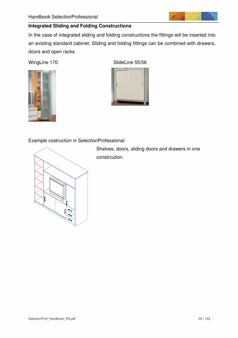
Handbook SelectionProfessional
SelectionProf_Handbook_EN.pdf 65 / 143
Integrated Sliding and Folding Constructions
In the case of integrated sliding and folding constructions the fittings will be inserted into
an existing standard cabinet. Sliding and folding fittings can be combined with drawers,
doors and open racks.
WingLine 170 SlideLine 55/56
Example costruction in SelectionProfessional:
Shelves, doors, sliding doors and drawers in one
constrcution.

3.14.2 Selection of Fittings in SelectionProfessional
The desired sliding and folding construction can be selected from the Construction
Assistant.
The following constructions are possible:
- Sliding door cabinet overlay
- Sliding door cabinet inset
- Folding door cabinet
- Folding-sliding door cabinet
Carcase details can be defined like in any standard cabinet. Please note that the usage
of fittings is dependent on the specified carcase dimensions.

Handbook SelectionProfessional
SelectionProf_Handbook_EN.pdf 67 / 143
3.14.3 Fitting: TopLine 22 standard doors
Input / Options in SelectionProfessional
Construction: sliding door cabinets / overlay
Carcase size: Height = 300 – 3500 mm
Width = 1000 – 4500 mm
The minimum width is dependent on the door width. The
minimum door width is 500mm.
With 2 doors min. carcase width = 1000mm,
with 3 doors min. carcase width = 1500mm
Cabinet side: Thickness = 5 – 100 mm
Base: Door distance / panel height = 50 – 300mm
Door division: Guide tracks= double tracked
Number of doors= 2 or 3
Depending on the number of doors, the respective set of
fittings will be selected.
Widths of doors = 500 – 2000 mm
Front details: Door thickness front = 16 – 28 mm
Door thickness back= 16 – 28 mm
Depending on the door thickness, the respective set of
fittings will be selected.
16 – 21mm > door center distance 29mm
22 – 28mm > door center distance 36mm
Front gaps left = 0 – 60mm
Front gaps right = 0 – 60mm

3.14.4 TopLine 25/27
Input / Options in SelectionProfessional
Construction: Sliding door cabinet / inset
Carcase size: Height = 300 – 3500 mm
Width = 1000 – 4500 mm
The minimum width is dependent on the door width. The
minimum door width is 500mm.
With 1 door and 2 doors min. carcase width = 1000mm,
with 3 doors min. carcase width = 1500mm,
with 3 doors min. carcase width = 1500mm
Cabinet side: Thickness = 5 – 100 mm
Base: Door distance / panel height = 50 – 300mm
Door division: Guide tracks = single tracked / double tracked
Number of doors = 1 (only single tracked), 2 or 3
Depending on the door thickness, the respective set of
fittings will be selected
Door width = 500 – 1500 mm
Front details: Door thickness front = 16 – 45 mm
Door thickness back = 16 – 45 mm
Front gaps left = 0 – 60mm
Front gaps right = 0 – 60mm
The bottom runner (STB 11,12,15,35) will be selected through the accessory in the
catalogue.

Handbook SelectionProfessional
SelectionProf_Handbook_EN.pdf 69 / 143
3.14.5 Fitting: TopLine 1
Input / Options in SelectionProfessional
Construction: Sliding door cabinet / inset
Carcase size: Height = 300 – 3500 mm
Width = 1000 – 4500 mm
The minimum width is dependent on the door width. The
minimum door width is 500mm.
With 2 doors min. carcase width = 1000mm,
with 3 doors min. carcase width = 1500mm
Cabinet side: Thickness = 5 – 100 mm
Base: Door distance / panel height = 50 – 300mm
Door division: Guide tracks = double tracked
Number of doors = 2 / 3
Depending on the number of doors, the respective set of
fittings will be selected
Door widths = 500 – 2000 mm
Front details: Door thickness front = 16 – 30 mm
Door thickness back= 16 – 30 mm
Front gaps left = 0 – 60mm
Front gaps right = 0 – 60mm
The bottom runner (STB 11,12,15,35) will be selected through the accessory in the
catalogue.

3.14.6 Fitting: WingLine 770/780
Input / Options in SelectionProfessional
Construction: Folding door cabinet
Carcase size: Height = 300 – 2200 mm
Width = 500 – 2400 mm
The minimum width is dependent on the width of the door
wing. The minimum width of the door wing is 245mm.
With 2 wings min. carcase width = 500mm,
with 4 wings min. carcase width = 1000mm
Cabinet side: Thickness = 5 – 100 mm
Base: Door distance = 15 – 1000 mm
Front details: Thickness = 16 – 25 mm
Edge curve = 10mm – 99mm
The curved edge will not be displayed, but should be
defined for safety reasons (risk of injury)!
Front overlay left = 1 – 15 mm
Front overlay right = 1 – 15 mm
Front overlay top = 1 – 99 mm
Clearance = 1 – 5 mm
Door stop = right, left, right and left
Depending on the door stop, the respective set of fittings
will be selected.
Front details / Hinge: Number = 4 - 8
Division = freely > distance between the first and last
hinge
Top distance = 50 – 500 mm
Bottom distance = 50 – 500 mm

Handbook SelectionProfessional
SelectionProf_Handbook_EN.pdf 71 / 143
3.14.7 Fitting: WingLine 77
Input / Options in SelectionProfessional
Construction: Folding door cabinet
Carcase size: Height = 300 – 2400 mm
Width = 500 – 2400 mm
The minimum width is dependent on the width of the door
wing. The minimum width of the door wing is 245mm.
With 2 wings min. carcase width = 500mm,
with 4 wings min. carcase width = 1000mm
Cabinet side: Thickness = 5 – 100 mm
Base: Door distance / panel height = 15 – 1000 mm
Front details: Thickness = 16 – 25 mm
Edge curve = 10mm – 99mm
The curved edge will not be displayed, but should be
defined for safety reasons (risk of injury)!
Front overlay Left = 1 – 15 mm
Front overlay Right = 1 – 15 mm
Front overlay Top = 1 – 99 mm
Clearance = 1 – 5 mm
Door stop = right, left, right and left
Depending on the door stop, the respective set of fittings
will be selected.
Front details / hinge: Number = 4 - 8
Division = freely > distance between the first and last
hinge
Top distance = 50 – 500 mm
Bottom distance = 50 – 500 mm

3.14.8 Fitting: Wing 77
Input / Options in SelectionProfessional
Construction: Folding-sliding door cabinet
Carcase size: Height = 300 – 2400 mm
Width = 500 – 2400 mm
Cabinet side: Thickness = 5 – 100 mm
Base: Door distance / panel height = 45 – 1000 mm
Front details: Thickness = 16 – 25 mm
Edge curve = 10 – 99mm
The curved edge will not be displayed, but should be
defined for safety reasons (risk of injury)!
Front overlay Left = 1 – 15 mm
Front overlay Right = 1 – 15 mm
Front overlay Top = 1 – 99 mm
Number of doors: the amount of doors will be calculated
based on the width of the carcase.
Carcase width 500 – 1000 > 2 wings
Carcase width 1001 – 2000 > 4 wings
The maximum door wing width is 400mm.

Handbook SelectionProfessional
SelectionProf_Handbook_EN.pdf 73 / 143
3.14.9 Integrated Sliding and Folding Door Constructions
The sliding and folding option is directly selected from Assistant – Carcase divisioning.
First, a standard cabinet (overlay or inset) is defined.
After that center panels and construction shelves are used to divide the cabinet and
create different zones. In each individual zone, sliding and folding doors can be
inserted. Different types of fittings can be used every other zone.
One zone can be equiped with doors, another one can be equiped with drawers. A third
one could be equiped with a sliding or folding door.
The respective zone needs to be marked in green (Zone mode). From the Assistant
choose Insert sliding/folding doors.
A window opens with the different types of fittings.
Different types of fittings are suitable for certain zone sizes:
Type of fitting Zone height Zone width Zone depth
Slide Line 55/56 300 - 2000 300 – 3000 50 - 2000
Top Line 110 300 - 2000 300 – 3000 50 - 2000
Wing Line 170 300 – 2250 300 – 1250 340 - 2000
Wing Line 26 800 – 1850 300 – 1050 50 - 2000

3.14.10 Slide Line 55 / 56
Front details
Doors – backset value: 0 – 100 mm
Door thickness front / back: 15 / 16 / 18 / 19 / 22
Front gaps – laterally: 0 – 20 mm
Door division
Guiding tracks single track / double track
Number of doors 1 (only single track), 2 or 3
Sequence of doors left door behind right door / right door behind left
door
Door width Same door width / Identical view
Overlapping 0 – 60 mm
Door spacing Clear / Fixed
Clear = Door spacing can be selected
freely between 6 – 50 mm.
Fixed = A fixed screw-on running profile
will be selected.
Distance value = freely = 6 – 50mm,
fixed= depending on door thickness

Handbook SelectionProfessional
SelectionProf_Handbook_EN.pdf 75 / 143
3.14.11 Top Line 110
Front details
Doors – backset value 0 – 100 mm
Door thickness front / back 15 / 16 / 18 / 19 / 22
Front gaps – laterally 0 – 20 m
Door division
Guiding tracks single track / double track
Number of doors 1 (only single track), 2
Sequence of doors left door behind right door / / right door behind left
door
Door width Same door width / dentical view
Overlapping 0 – 60 mm
Door spacing spacing between doors is set to 10 mm

3.14.12 Wing Line 170
Division
Align hinge to hole line On / Off
Construction type Stop left / Stop right / double door
for carcase widths > 640mm, a double door will be
selected automatically.
Thickness 15- 28 mm
Hinge
Number number of hinges
Optimum amount infofield, The opt. number of hinges can be undercut at the
user’s own risk. A warning will show up.
Division division of hinges in door
Edge curve used to calculate the C-measurement / distance plate but
not displayed in the drawing
Opening angle to specify the opening angle of the door
The different folding door hinges can be selected from the catalogue.
The mounting position of the guiding bar will be disregarded.

Handbook SelectionProfessional
SelectionProf_Handbook_EN.pdf 77 / 143
3.14.13 Wing Line 26
Division
Align hinge to hole line On / Off
Construction Stop left / Stop right / double door for carcase widths >
500mm,stop left and stop right will be selected
automatically.
Thickness 15- 28 mm
Clearance 1 – 5 mm
Overlay left 1 – 15 mm
Overlay right 1 – 15 mm
Hinge
Number number of hinges
Optimale Anzahl infofield, The opt. number of hinges can be undercut at the
user’s own risk. A warning will show up.
Division division of hinges in door
Edge curve used to calculate the C-measurement / distance plate but
not displayed in the drawing
Opening angle always with 110° hinges
The different folding door hinges can be selected from the catalogue.

3.15 Placing Handles on Sliding and Folding Doors
3.15.1 Placement Choices
Handles and knobs can be placed on sliding and folding doors similarly to drawers and
doors. However, there are differences based on the arrangement of the doors.
3.15.2 Placement of Handles
1) Select the sliding or folding door in the (red) constructive part mode.
2) Choose „Select/change knobs/handles“ from the Assistant. The construction is
displayed in the front view.
3) Especially in sliding and folding door constructions with several doors, it is necessary
to place the handles on different positions. By default the handles are placed on all
selected fronts marked in red. To avoid this, fronts can be selected individually.
Process:
Initially all fronts are marked in red. To select the handle
position only for the left sliding door, click on the middle
and right door to unselect them.
Subsequently, the handle position will be selected for the
left door by choosing „middle left“ for example. Confirm
you selection by clicking on the green checkmark.
The handles for the remaining doors are placed likewise.

Handbook SelectionProfessional
SelectionProf_Handbook_EN.pdf 79 / 143
3.16 Kitchen Constructions
3.16.1 Construction types
A separate kitchen constructions section has been created. These constructions are
specifically aimed at the kitchen area, which means for example that all panel
dimensions are optimised for a perfect kitchen environment.
The kitchen constructions are divided into the sections base cabinet / top unit / tall
cabinet. The base unit section is furthermore divided into the areas standard base
cabinet and corner cabinet.
Dimensional references and design details are furnished in the
“SelectionProf_Library_EN.PDF “handbook.
3.16.2 Full circle carousel fitting
Input / choice in SelectionProfessional
Carcase size
Mounting situation: Choice of fitting type
750 Arena, 750 Wire, 750 Wire white, 650 Wire white
Only the relevant accessories must be chosen from the
catalogue, if necessary.
Width: Dimension A
Complete external carcase width
Carcase side left / front: Dimension B
External carcase side depth. These always have the same
value.
Door width: Dimension C
The door width is an info field and is calculated from the
width of the carcase side left / front.

Construction information: The carcase is made with an 8 mm back panel. The rear
back panel is constructed from 16/18/19 top thickness.
Base
An angled base represents a special situation with regards to base recess. The base
recess measurements (from the front) normally relate to a 90° angle between the
bottom shelf and the front edge of the base.
If the same measurements were used for an angled cabinet as for a normal base
cabinet, the two base fronts would not fit together.
The programme therefore allows for the recess measurement in relation to the carcase
side to be specified. The distance in the 90° angle is given as info text.
Fitting information
Mounting top panel: centre hole (D=5 mm, T=8 mm) + 3 fixing holes
Mounting bottom panel: 3 fixing holes. To enable better centring and positioning of
the revolving plate, a punch point has been provided in the
centre of the fitting. There is no need for mounting or
drilling at this point.
Choice of hinge: The door construction requires angled hinges (W45).
These can be chosen from the catalogue.
Corner carousel fitting: The full circle carousel fitting can be chosen from the
catalogue. The set already contains two revolving bases so
that these do not need to be chosen separately.

Handbook SelectionProfessional
SelectionProf_Handbook_EN.pdf 81 / 143
3.16.3 Segmented carousel fitting
The segmented carousel fitting is identical with the full-circle carousel in terms of
carcase size and fitting choice.
3.16.4 Three quarter carousel fitting
Input / choice in SelectionProfessional
Carcase size
Mounting situation: Choice of fitting type700 Arena, 820 Wire, 700 Wire, 820 Wire,
700 Wire white, 820 Wire white
Only the relevant accessories must be chosen from the
catalogue, if necessary.
Carcase side left / front: Dimension A
External carcase side depth. These always have the same
value.
Opening width: Dimension B
Aperture for the door

Front information
Door variants: The doors are available in different construction types:
Equal
Left short
Right short
Folding door stop left
Folding door stop right
Fitting information
The options equal, left short and right short are carried out with Intermat hinges (125-
165° opening angle).
The options Folding door stop left and Folding door stop left are offered in combination
with a wide angle hinge and a corner cabinet folding door hinge.

Handbook SelectionProfessional
SelectionProf_Handbook_EN.pdf 83 / 143
3.16.5 Corner cabinet Revo 45
Input / choice in SelectionProfessional
Carcase size
Carcase height: The carcase height of the Revo 45 and 90 is not identical with the
carcase height of a normal base cabinet.
The fronts of the Revo 45/90 rotate inside the carcase when being opened. Both
construction types therefore have no top panel. There is a clearance gap between the
front and the bottom panel. If a Revo 45/90 cabinet is constructed at the same height as
a normal base cabinet, both fronts would be offset at the bottom. The ordinary base
cabinet features an overlay on the bottom panel. The front of the Revo 45/90 has a
recess to the bottom panel (clearance).
A = corner cabinet Revo 90/45; H = 747mm
B = normal base cabinet; H = 720mm
1 = bottom panel corner cabinet
2 = bottom panel normal cabinet
C = bottom panel overlay
Overlay = 16 mm, clearance = 4mm
11 mm = gap between door and bottom panel with Revo 90/45
27 mm = offset value of carcase height, 720 mm + 27 mm = 747 mm

Carcase width: The carcase width and side depth are fixed and cannot be changed. They are in line with ideal fitting values.
Front: A straight wooden front is fitted. The stainless steel finish
front is not being considered.
The front measurements can be fixed depending on side
panel thickness.
Side panel
thickness
A - opening width B - door width
19 454 446
18 456 448
16 458 450

Handbook SelectionProfessional
SelectionProf_Handbook_EN.pdf 85 / 143
Bottom panel / base
The bottom panel is recessed by 40 mm in order to be invisible from the outside. This
also allows for the side to be notched. The base is thus offset in relation to the bottom
panel by another 10 mm towards the back.
A = bottom panel, recessed by the value x1
B = bottom panel, recessed by the value x2
C = door
Side notch = 11 mm + bottom panel thickness

3.16.6 Corner cabinet Revo 90
Input / choice in SelectionProfessional
Carcase size
Mounting situation: There is a choice between the carcase sizes 800*800 and
900*900.
Carcase height: Starting basis analogous to Revo 45
Carcase width: The carcase width and side depth are fixed and cannot be
changed. They are in line with ideal fitting values.
Top panel The Revo 90 does not feature a top panel.
Bottom panel / base The construction of recess measurements for bottom
panel and base is identical with that for Revo 45.

Handbook SelectionProfessional
SelectionProf_Handbook_EN.pdf 87 / 143
3.16.7 Semi circle carousel fitting
Input / choice in SelectionProfessional
Left / right variation
The semi circle carousel fitting is available in a left and right version. The two
construction types are laterally reversed. The fittings for both versions are identical.
Left option Right option
Carcase size
Mounting situation: There is a choice between
850 Arena, 850 Wire and 750 Arena.
Width: Dimension A, carcase width
Door width: Dimension B, door width
Mounting width: Dimension C, info field, non-changeable, important for the
installation of the next base cabinet
Door opening width: Dimension D, info field, non-changeable
Depth: Dimension E, carcase depth
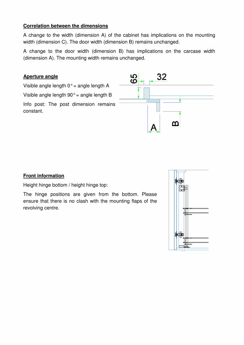
Correlation between the dimensions
A change to the width (dimension A) of the cabinet has implications on the mounting
width (dimension C). The door width (dimension B) remains unchanged.
A change to the door width (dimension B) has implications on the carcase width
(dimension A). The mounting width remains unchanged.
Aperture angle
Visible angle length 0° = angle length A
Visible angle length 90° = angle length B
Info post: The post dimension remains
constant.
Front information
Height hinge bottom / height hinge top:
The hinge positions are given from the bottom. Please
ensure that there is no clash with the mounting flaps of the
revolving centre.

Handbook SelectionProfessional
SelectionProf_Handbook_EN.pdf 89 / 143
4. Selection CAD (AutoCAD) Principles
4.1 Introduction to CAD
The Designer part of Selection Professional allows you to create, modify and save
complete cabinet designs. Automatic measuring using the Document Manager can also
be started from the Designer
The AutoCAD section is used primarily for the following:
- Exact 3D view and display, with all details of fittings and design elements
- Dimensioning individual components selected
- Dimensioning the carcase view
- Exporting the cabinet in DWG/DXF format
- Cabinet print-out / plot
Roomplan is based on the AutoCAD system and is therefore also started from the
AutoCAD environment.
4.2 AutoCAD surface
4.2.1 Menu functions
File
New Creates an blank page
Import Imports AutoCAD drawings
Export Exports AutoCAD drawings
Plot Prints the current drawing
Preferences AutoCAD settings; do not change
End Ends the program. Selection Professional should be closed through
the Designer and not using this AutoCAD function.
Edit
Undo Reverses a step in a function
Repeat Repeats a step in a function
Info CAD Information on a component
Info Designer Information on a component
Delete cabinet Deletes an entire cabinet
Delete cabinet from list Deletes a specific cabinet from several inserted cabinets
Delete Part Deletes individual lines, dimensions, decorative elements etc.

View
Display details … Sets the viewing details. There is a speed advantage in lower
representations, particularly with more complex designs.
Low = Display cabinet contours, no fittings
Medium = Includes fittings in the display
High = Displays fittings and drill holes
Drawing … Sets the various AutoCAD views.
Zoom > Various options for zooming in and out
BKS-Symbol on/off Enables or disables the coordinates
Pan Move drawing
Hide edges Provides a partly hidden view of the cabinet. Note: this view is not
automatically printed.
3D wire model Makes circles clearer, switches from hidden mode back to wire.
3D surface display Shades the surface
Colored display displays the design with the selected outer surface
Set up project Displays the typed component only
Hide elements Hides individual sides, walls etc.
Display all Shows all sides, walls etc again.
Assistant If the Assistant is switched off, it can be switched back on again using
this function.
Tools
Dimension Part > Selects component dimensioning
Manual dimension Dimensioning function for cabinet views
Measure Measures a defined distance
Image output on …> Prints out the screen content. The content can also be copied to a file.
Text Adds a text commentary to the drawing.
Toolbox > Contains simple drawing commands
Window In Selection Professional there is a main window that displays the
current Designer drawing. This window must never be closed. Other
windows may be opened in addition to this window in order to plan a
room plan alongside your Designer work.
The individual windows are displayed in the menu.
? Information on Selection Professional

Handbook SelectionProfessional
SelectionProf_Handbook_EN.pdf 91 / 143
4.2.2 AutoCAD icon functions
The icons are described from left to right.
- creates a new request
- Opens an existing file or looks for it
- Saves the active file with the current file name, location and file format
- Prints the active drawing. Click on Print in the File menu to select print options
- Undoes the current action. Goes back one step in the list of actions
- Repeat action. Repeats the most recent action
- Pressing this button displays the entire design on the screen
- Pressing this button magnifies an area of the design
- Pressing this button magnifies the screen view of the design
- Pressing this button reduces the screen view of the design
- Zooming in real time. Press the left mouse button to zoom into the screen view
- Pan function. The screen view can be shifted by holding the left mouse key down
- Top view. View of the design from above
- Side view left. View of the design from the left
- Side view right. View of the design from the right
- Front view. View of the design from the front
- Back view. View of the design from behind
- Isometric view south-west
- Isometric view south-east
- Isometric view north-east
- Isometric view north-west
- 3D orbit. In this view, the room can be moved freely in any direction.
- 3D wire model function
- Hide edges
- 3D surface display
- Colored display
- Light symbols on/off
- Delete Part. Deletes an entire cabinet.
- The design you want to delete can be selected after clicking this button
- A highlighted component can be deleted after clicking this button. Click the button.
The cursor changes. Highlight a component and then press on ENTER
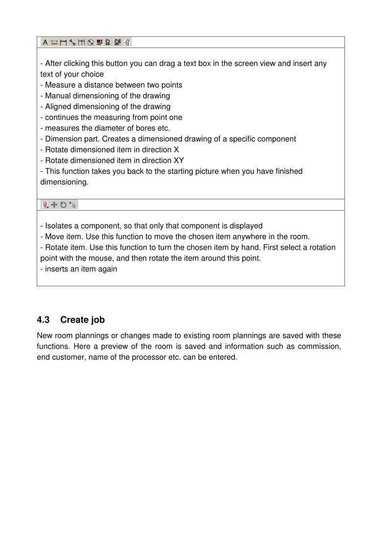
- After clicking this button you can drag a text box in the screen view and insert any
text of your choice
- Measure a distance between two points
- Manual dimensioning of the drawing
- Aligned dimensioning of the drawing
- continues the measuring from point one
- measures the diameter of bores etc.
- Dimension part. Creates a dimensioned drawing of a specific component
- Rotate dimensioned item in direction X
- Rotate dimensioned item in direction XY
- This function takes you back to the starting picture when you have finished
dimensioning.
- Isolates a component, so that only that component is displayed
- Move item. Use this function to move the chosen item anywhere in the room.
- Rotate item. Use this function to turn the chosen item by hand. First select a rotation
point with the mouse, and then rotate the item around this point.
- inserts an item again
4.3 Create job
New room plannings or changes made to existing room plannings are saved with these
functions. Here a preview of the room is saved and information such as commission,
end customer, name of the processor etc. can be entered.

Handbook SelectionProfessional
SelectionProf_Handbook_EN.pdf 93 / 143
4.3.1 Comparison of the individual save functions in SelectionProfessional
Saving in Designer The cabinet that has been created in the Designer is
saved. The cabinet is saved in a predefined
directory, which can be optionally expanded. The
directory path is on C:\Selection\User\CAD (here
C:\Selection is the installation directory of
SelectionProfessional)
File > Export in Designer To open cabinets on another computer with the help
of SelectionProfessional, they have to be exported
first. For this the cabinet should not be open in
Designer. If the function”Export“is selected in File
menu, the cabinets that have to be exported should
be selected first. The second step is to specify a
target folder. Any directory can be specified as the
target folder. Subsequently the cabinet can be
copied into the directory with the File -> Import
function. It can be now opened here.
Create job/project The “create job / project” function is used to save a
new spatial planning. All information about this job is
stored in a database.
File > Export in SelectionCAD To open spaces on another computer with
SelectionProfessional, they should be exported first.
The room/space should be open. After clicking on
the “Export” function in File menu in SelectionCAD,
a target folder is specified. Subsequently the room
can be opened on another computer with the File ->
Import function in SelectionCAD. In order to open
this room in the future with the” Load job/project”
function, it should be first saved with the “Save
job/project” function.

4.3.2 Create job/project
New spatial/room planning is saved with the “Create job/project“function.
To create a new job, it is necessary to create a new room situation. Otherwise it will not
be possible to create additional information.
The dialogue “Save job“is opened after calling the function.
Here the job name (1) and the additional information (2) is entered and saved with the
green check mark. Subsequently the job name is saved in the job list (4).
The preview (3) is created with the help of the view in SelectionCAD. It is not
considered here, whether the edges have been hidden beforehand.
All jobs that have been opened until now (5) are listed in the list of opened jobs.
Handbook SelectionProfessional
SelectionProf_Handbook_EN.pdf 95 / 143
The menu bar (6) is configured as follows:
• deletes an existing job
• creates a new directory in the job list
• updates the job list
• searches for a job
• calls Help
4.3.3 Load job / project
All available room plannings are opened with the “load job/project” function. The
dialogue corresponds to the Save job dialogue.
4.3.4 Save job / project
All changes made to the available room plannings are saved with the “Save
job/project“function. The existing job is overwritten.

4.4 Measuring
4.4.1 Dimension part
Click “Dimension Part” to dimension various components of a cabinet (sides,
shelves, doors etc.).
Clicking the “Dimension Part” button changes the mouse pointer into a small box. Click
the box on the outline of the component (see figure below). The component will then be
displayed with its dimensions.
To dimension other parts, click the "Dimension Part" button again and select another
component. Click the Return to CAD button to finish dimensioning
With the “Rotate measured item X“button and “Rotate measured item XY“ button,
the measured components can be rotated.
The type of dimensioning can be set under “Tools / Dimension Part / Settings …”.
Style
Absolute = absolute dimensioning of the bottom left side of the carcase
Hole centre to hole centre = relative dimensioning from drill hole to drill hole

Handbook SelectionProfessional
SelectionProf_Handbook_EN.pdf 97 / 143
Unit
millimetre = sets dimensioning to mm units
inch = sets dimensioning to inch units
Generate infotext = if this option is activated, information such as slot depths, drill
diameters, drilling depths etc. is also shown.
4.4.2 View dimensioning
You can perform your own dimensioning by using
the “Apply Measure” button or ”align with
dimensioning“ . You can, for example, select the
front view of the cabinet and dimension it yourself.
To do this, select the function and enter the point
where dimensioning is to start. Click on the carcase
edge and set the starting point of the dimensioning,
then select the point where dimensioning is to end,
followed by the position of the measurement line.
The program supports you with automatic capture
functions. This means that it automatically looks for
and finds the end of a line. This is indicated by a
small violet square. Once you see this, all you have
to do is left-click the mouse and the end point is
recognised.
With the “Continue dimensioning” button , it is possible to attach a chain
dimensioning to the most recently created dimensioning.
With the “diameter” button, curves and circles can be measured.
With the “measure” button, it is possible to remove a measure from the view, without
the creation of a dimensioning. The measured space can be read in the status bar.
With the “Text” button , it is possible to write text information in the view, so that it
can be printed along with.

4.4.3 Cabinet views
With the help of the menu item “View / display details“, the view details scale can be set.
- Low: Only handles and components are displayed. This accuracy of detail is especially
suitable for room planning.
- Medium: Components, handles and fittings are displayed without processing.
- High: Components, handles and fittings are displayed along with processing.
With the help of the View button or the menu option “View/designs-… “, a cabinet
display can be selected.
“Hide edges” gives you a partly hidden view of the cabinet.
With the “3D area representation“, a hidden and colored view of the
cabinet is available.

Handbook SelectionProfessional
SelectionProf_Handbook_EN.pdf 99 / 143
4.5 Printing/plotting
In order to understand the following points on the subject of printing/plotting, it is better
to implement a cabinet design beforehand.
Screen layout
Everything that can be displayed on the screen can also be printed. These may include
perspective views of a cabinet, dimensioned components (side panels, top panels,
bottom panels, etc.) or enlarged sections or room views.
Before you print a drawing, it is a good idea to display it on the screen in the way you
want to print it. For instance, if you want to print a perspective view of a cabinet, then
position the drawing as shown below. The quickest way to arrange a drawing as shown
below is by clicking the Full view button. If you only want to print a section of the
cabinet, e.g. a corner connection, use the Zoom window button.
If the hidden cabinet edges are not to be printed, the “Hide edges“button or the
menu “View / hide edges” is used so that the invisible edges are deactivated. However if
a color printout of the drawing is required, it should be displayed with colored areas. The
printout always corresponds to the display on the screen.

Call function
Once the drawing is in the ideal position on the screen, click the “Plot” button or
select “File / Print” from the menu. This opens the Plot window where you can enter all
the main print settings.
Select printer
In the Printer/plotter section (1) the required printer should be specified near the field
“Name“. If this field contains the entry “none”, the printer can also be selected from the
Pull-Down-Menu (2).
Paper format: (3) this is where you select the paper format. The size depends on the
capabilities of your printer/plotter.
Plot area (4): The pull downlist contains the options view, window, limits.
Display: Selecting this item prints the screen content exactly as displayed.
Window: If this point is selected, you can enter a specific print area (see a later
example).
Limits: With these points the complete drawing is printed. A previously defined zoom is
not considered.

Handbook SelectionProfessional
SelectionProf_Handbook_EN.pdf 101 / 143
Plot scale: (5) This is where you can enter a scale. Once adjusted the drawing fits the
page perfectly. You can also select scales, such as 1:2, 1:4 etc.
Plot distance: (6) If the Centre plot option is selected, the position of the drawing on the
paper will be optimised in height and width. An entry in x and y produces a side margin
of the sizes entered.
Preview(7): printout on the paper can be seen beforehand as a preview on the screen.
Page setup (8): the settings can be saved under a name in the plot dialog. Click on the
„add to“button and specify a name.
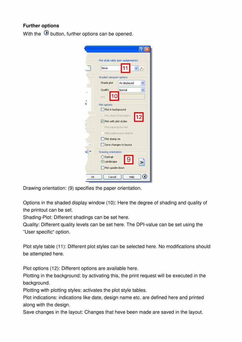
Further options
With the button, further options can be opened.
Drawing orientation: (9) specifies the paper orientation.
Options in the shaded display window (10): Here the degree of shading and quality of
the printout can be set.
Shading-Plot: Different shadings can be set here.
Quality: Different quality levels can be set here. The DPI-value can be set using the
”User specific“ option.
Plot style table (11): Different plot styles can be selected here. No modifications should
be attempted here.
Plot options (12): Different options are available here.
Plotting in the background: by activating this, the print request will be executed in the
background.
Plotting with plotting styles: activates the plot style tables.
Plot indications: indications like date, design name etc. are defined here and printed
along with the design.
Save changes in the layout: Changes that heve been made are saved in the layout.

Handbook SelectionProfessional
SelectionProf_Handbook_EN.pdf 103 / 143
Example 1
You want to print the cabinet previously displayed. Go to the File menu and select the
Print command. Select the correct printer from the plotter tab. Then return to the plotter
settings (2). Select the appropriate paper format, e.g. A4. Select the Display option. (3)
Click the Preview button (7). The picture shows the drawing as it will be printed on
paper. Exit this window either by right-clicking the mouse and selecting End from the
window, or by pressing the Esc key.
To print the drawing, click the OK button in the Plot window (12).
Example 2
You can, of course, print individual components as well as whole cabinets. In the
following example we want to print one carcase side panel. Click “Dimension Part” and
mark a carcase side panel with the small box. Now you will see a top view of the
dimensioned side panel. Click “Zoom
Start print control as described in example 1. Select the entry Window from the pull
down list in the plot area section (4). This will take you back to the design window,
where you will see your drawing.
Use the mouse to select a section to be printed. Then move the mouse into the top left
corner of the drawing and left-click.
Then move the mouse to the bottom right corner of the drawing and left-click again.
Subsequently the plot dialog box can be seen. This right corner area is the one, that will
be printed later. The”Window” button can be used to define thus area again.
If you click on button (7) again, you will receive a display of exactly the same area that
you selected before.
You can exit this window by a right click of the mouse and select the entry “end“ in the
window.
To print the drawing, click on “OK“.
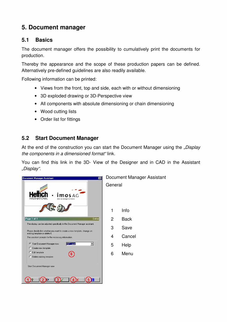
5. Document manager
5.1 Basics
The document manager offers the possibility to cumulatively print the documents for
production.
Thereby the appearance and the scope of these production papers can be defined.
Alternatively pre-defined guidelines are also readily available.
Following information can be printed:
• Views from the front, top and side, each with or without dimensioning
• 3D exploded drawing or 3D-Perspective view
• All components with absolute dimensioning or chain dimensioning
• Wood cutting lists
• Order list for fittings
5.2 Start Document Manager
At the end of the construction you can start the Document Manager using the „Display
the components in a dimensioned format“ link.
You can find this link in the 3D- View of the Designer and in CAD in the Assistant
„Display“.
Document Manager Assistant
General
1 Info
2 Back
3 Save
4 Cancel
5 Help
6 Menu

Handbook SelectionProfessional
SelectionProf_Handbook_EN.pdf 105 / 143
5.3 Start Document Manager now
To start document collection output straight away, select one of the pre-defined
templates from the list (1) and then click “Save”.
This initiates output, and the document
collection is automatically generated.
The document preview opens automatically
at the end. If the documents are to be
printed, click on the small printer symbol
at the top left of the menu bar.
Click the “X” to close.
5.4 Create new template
To create a new template, enter a new name
in field (1) at first, and then click “Save“.

5.4.1 Sizing views
Subsequently the settings for the first pages would be carried out.
Then with “Save“.
5.4.2 Layout
In the second step, the settings regarding how the 4 cabinet views should be presented,
would be adjusted. In any case the type of dimensioning would be adjusted.
Then with “Save“.
1 Definition exploded drawing
2 Definition front view
3 Definition side view
4 Definition top view
1 Page layout
2 Definition of sizing
3 Display help texts. e.g. drilling
diameters and depths
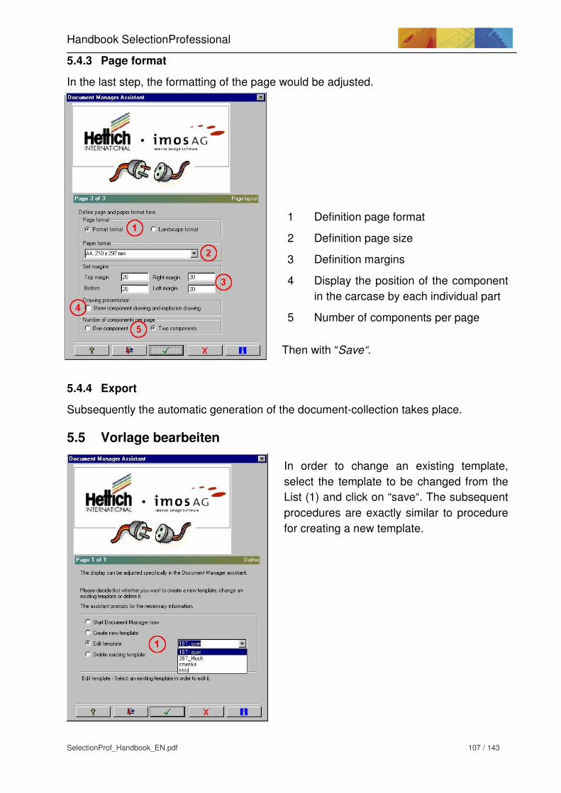
Handbook SelectionProfessional
SelectionProf_Handbook_EN.pdf 107 / 143
5.4.3 Page format
In the last step, the formatting of the page would be adjusted.
Then with “Save“.
5.4.4 Export
Subsequently the automatic generation of the document-collection takes place.
5.5 Vorlage bearbeiten
In order to change an existing template,
select the template to be changed from the
List (1) and click on “save“. The subsequent
procedures are exactly similar to procedure
for creating a new template.
1 Definition page format
2 Definition page size
3 Definition margins
4 Display the position of the component
in the carcase by each individual part
5 Number of components per page
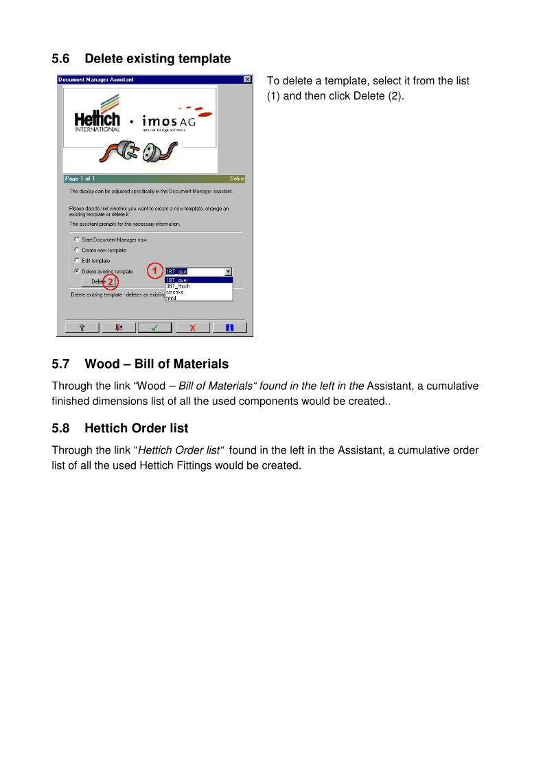
5.6 Delete existing template
To delete a template, select it from the list
(1) and then click Delete (2).
5.7 Wood – Bill of Materials
Through the link “Wood – Bill of Materials“ found in the left in the Assistant, a cumulative
finished dimensions list of all the used components would be created..
5.8 Hettich Order list
Through the link “Hettich Order list“ found in the left in the Assistant, a cumulative order
list of all the used Hettich Fittings would be created.

Handbook SelectionProfessional
SelectionProf_Handbook_EN.pdf 109 / 143
6. Roomplan functions
6.1 Introduction
As a planning tool, Roomplan enables you to display cabinets created using Selection in
a room situation. Unlike previous 3-D planning systems, the user is guided through the
programme by ergonomic Assistants.
Only a limited amount of prior knowledge of CAD is required.
The main functions in Roomplan are:
• Selection of parametric layouts for walls, 3-D generation of various basic
configurations with simple walls, L- and U-walls.
• Creation of various window and door elements.
• Adjustment of floors and ceilings.
• Display of various views, isometry and vanishing point.
• Possibility to insert cabinet and decorative elements.
• Creation of work tops, plinth, cornice, front panels and visible sides.
6.2 Starting Roomplan
Roomplan is started from the “Selection CAD” programme section. From Designer, the
CAD section can be started with the “CAD/Roomplan” Assistant. Use the “Roomplan”
directory tag to call up the Roomplan Assistant.
Always select the “New room plan” function before starting Roomplan; this produces a
blank window.

6.3 Define wall
Start the Define wall function.
The Roomplan Assistant has various options for settings:
1. Definition of the wall type 2. This is where the size reference for the longitudinal details are set:
a) outer side of wall b) middle of wall c) inner side of wall (pre-set)
3. Details of wall height and thickness 4. This is where the wall lengths are given for the respective wall parts. 5. Close wall:
The starting and end points for the wall are automatically connected to close the room. Floor: A floor is put in the room. Ceiling: A ceiling is put in the room.
6. Details of wall and ceiling materials 7. Preview of the selected wall type in the appropriate length.
The corresponding surfaces are displayed for material selection.
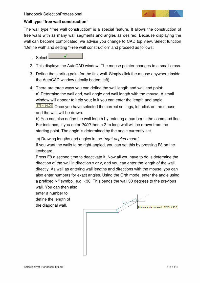
Handbook SelectionProfessional
SelectionProf_Handbook_EN.pdf 111 / 143
Wall type “free wall construction”
The wall type "free wall construction" is a special feature. It allows the construction of
free walls with as many wall segments and angles as desired. Because displaying the
wall can become complicated, we advise you change to CAD top view. Select function
“Define wall” and setting “Free wall construction” and proceed as follows:
1. Select .
2. This displays the AutoCAD window. The mouse pointer changes to a small cross.
3. Define the starting point for the first wall. Simply click the mouse anywhere inside
the AutoCAD window (ideally bottom left).
4. There are three ways you can define the wall length and wall end point:
a) Determine the wall end, wall angle and wall length with the mouse. A small
window will appear to help you; in it you can enter the length and angle.
Once you have selected the correct settings, left-click on the mouse
and the wall will be drawn.
b) You can also define the wall length by entering a number in the command line.
For instance, if you enter 2000 then a 2-m long wall will be drawn from the
starting point. The angle is determined by the angle currently set.
c) Drawing lengths and angles in the “right-angled mode”:
If you want the walls to be right-angled, you can set this by pressing F8 on the
keyboard.
Press F8 a second time to deactivate it. Now all you have to do is determine the
direction of the wall in direction x or y, and you can enter the length of the wall
directly. As well as entering wall lengths and directions with the mouse, you can
also enter numbers for exact angles. Using the Orth mode, enter the angle using
a prefixed “<” symbol, e.g. <30. This bends the wall 30 degrees to the previous
wall. You can then also
enter a number to
define the length of
the diagonal wall.

5. Repeat the procedure with the next wall segment.
It is also possible to incorporate curved walls. To do so, enter the letters “GE” in the
command line and press ENTER to confirm. Then use the mouse to select the middle of
the circular segment and the end point of the circle. If the next wall is to be straight,
enter “LI” for line and press ENTER to confirm.
When you have finished constructing the walls, just press ENTER to end the
construction.

Handbook SelectionProfessional
SelectionProf_Handbook_EN.pdf 113 / 143
6.4 Define windows / doors and openings
For windows, doors and openings, the style is chosen first and then the dimensions and
reference points.
The individual functions are explained here using the doors as an example. They are
the same
for windows and openings.
1) Select the door style (e.g. windows style, opening style)
2) Select the hinged side
3) Sizes: the width and height define the outer dimensions of the door. The door sill
defines the space between the bottom edge of the door and the floor. With double
doors, the details for the hinged side are not taken into account.
4) Doors (windows, openings) can be defined by a space to the reference points (end
wall segment).
5) With the “Position freely” option, the position is chosen freely with the mouse.
6) If an opening angle is entered, the door is shown opened by this angle.

Positioning the doors, windows, openings
Once the settings have been made, they are confirmed with the green tick. The AutoCAD window appears. Select a wall into which you want to put a door (or window, opening). You must get it right on the line for the wall in question. Depending on whether you click closer to the left or right corner of the wall, the reference point will be seen from this end.
6.5 Modifying windows / doors / openings
If you want to make changes to any doors, windows or openings that have already been
entered, do so with the “Change windows, doors and openings” function.
Proceed as follows:
1) Once you have chosen the function, highlight the door / window / opening in
question. You must click on one of this object’s lines.
2) This opens the relevant Assistant (door/window/opening). Make your changes and
confirm them with the green tick.
6.6 Deleting windows / doors / openings
Windows, doors and openings can be deleted with the “Delete part” icon on the
functions bar.
Select the “Delete part” icon and then click on the components concerned (window etc.).
Press ENTER to confirm the deletion.

Handbook SelectionProfessional
SelectionProf_Handbook_EN.pdf 115 / 143
6.7 Change the wall characteristics
With the function “change the wall characteristics”, the height, thickness, material and
alignment of the cabinet wall can be changed. After the function is clicked the cursor
becomes a small square. With this square, a line of the concerned wall is clicked. The
wall will be displayed as a dotted line. Here multiple walls can also be accessed one
after the other.
After all the walls to be changed are selected, this selection must be confirmed with a
right mouse click or with the Enter key on the keyboard. The dialog “edit wall“ is opened.
The settings will be saved by clicking
on the green tick and wall
characteristics are changed.
If the walls require further changes, the command “edit wall” should be accessed afresh.
1 Changes the wall height
2 Changes the wall thickness
3 Changes the material of the
wall
4 Changes the alignment of the
wall

6.8 Insert furniture or accessories
6.8.1 Select cabinet
You can incorporate the cabinets created in Selection Professional with function item "5.
Insert furniture and decorational elements”. You can also access a library that already
contains a number of standard cabinets.
Selecting this function opens a window. Select the appropriate drawing. When you
highlight a file name the corresponding view of the cabinet in question is displayed.
Select “Open” to load the selected cabinet.
6.8.2 Add furniture to a wall
Once you have selected a cabinet from the library, the mouse pointer changes to a
small square. Now click on the wall where you wish to stand the furniture. It is important
that you click exactly on the wall line. Once you have selected the wall, the carcase is
automatically orientated along it. Inserting and positioning cabinets is explained more
clearly by the following graphic.
The insertion point of the cabinet is defined by clicking on the grey buttons on the outer
corners of the displayed cube.
The current insertion point is shown in red. The insertion points need to be changed if,
for instance, you want to put the bottom right corner of a cabinet in the corner of the
room.
Current insertion point of the cabinet (here e.g. bottom /right)

Handbook SelectionProfessional
SelectionProf_Handbook_EN.pdf 117 / 143
In this case, we want the insertion point to be the back bottom right corner of the
cabinet.
Select this button. The red colour now indicates that it is active.
The cabinet is shown as a cube before it is put in its final position, and you can move it along the walls as you wish. Depending on the wall orientation, the cabinet will always adapt to the course of the wall.Seen from the top, the cabinet can now be pushed into the corner of the wall.
When the left mouse is clicked, it will be moved
here.
To move a cabinet out of the corner for a blend
bar, a value can be entered in the field “Distance
2“. In our example it is “-50mm“, to move the
cabinet to the left.
6.8.3 Inserting furniture in an existing object (furniture or decorative object)
If a cabinet has already been inserted, then it can be used as a reference object for an additional planned cabinet. The object can then be inserted anywhere to the right/left/front/back, top or bottom of the existing object.

Procedure Select an additional cabinet using the “Insert furniture and decorational elements” function. Click on the previously inserted cabinet to open a new window.
Use the grey alignment quadrats (1) to
determine the position of the new cabinet in
relation to the existing one.
Click on the alignment quadrat to insert the
cabinet correspondingly to the right, left, front,
rear, bottom or top.
“Gap1 (2)“ defines the gap to the existing
cabinet.
Repeat inserted item (3) permits direct insertion
of the same cabinet against an existing one.
Planning furniture with different depths (front or
back-flush)
If, for instance, a wall unit is being fitted, it can be orientated to the tall unit. Procedure:
1. Insert tall unit in Roomplan
2. Select wall unit
3. Select tall unit as reference point
4. Change tab (see illustration left)
5. Drag cabinet to top (1) and rear (2) on the grey quadrat.
6. Select green tick. Cupboard is inserted.
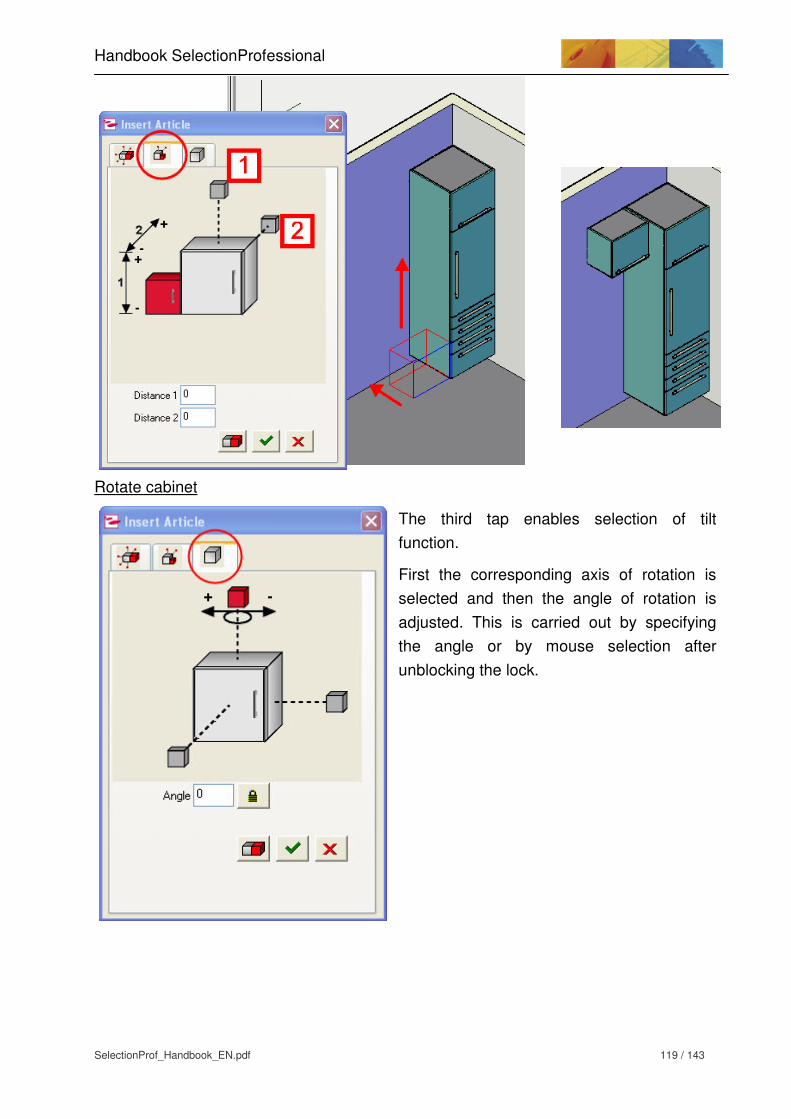
Handbook SelectionProfessional
SelectionProf_Handbook_EN.pdf 119 / 143
Rotate cabinet
The third tap enables selection of tilt
function.
First the corresponding axis of rotation is
selected and then the angle of rotation is
adjusted. This is carried out by specifying
the angle or by mouse selection after
unblocking the lock.
6.9 Delete item
Select the Delete item icon in the Selection Button bar. Then select the cupboard or object you wish to delete.
6.10 Move / rotate item
If you want to move a cupboard or other object, select the Move item icon from the Selection Button bar. Then left-click on the object to select it, define the base point on the object you want to move, and move it to the desired position. If you want to rotate a cupboard or an object, select the Rotate item icon from the menu. Then select the object you wish to rotate. Determine the position of the rotation point and enter the rotation angle. You can do this either by moving the mouse or by entering the rotation angle (+ left, - right)
6.11 Select and insert decorative elements
In order to display the room situation as realistically as possible, the system already contains a number of furnishing elements that can be included in the plan. Activate the Insert furniture and decorational elements option from the Deko folder. This folder contains a variety of subdirectories for various furnishing areas. Select the desired decorative element. The AutoCAD main window appears, and the mouse pointer changes to a small square. You can now select a wall, a cupboard or the floor to position the decorative element on or against. Decorative elements can be inserted in exactly the same way as cupboards.

Handbook SelectionProfessional
SelectionProf_Handbook_EN.pdf 121 / 143
Example: Inserting a sink unit
In the following example it is displayed how a sink unit can be inserted in a kitchen
counter. The kitchen counter has already been created and the sink unit should be fitted
over the second cabinet from the left.
Now the sink unit would be selected using “Insert furniture or design elements” and the
second cabinet from left is selected as the reference object.
Subsequently the alignment square for the top is selected in the dialog “insert article”
and the thickness of the work top (38mm) is entered in the field “Distance1“.

To get a preview on the CAD-window, the enter key must be pressed after the entry of
distance 1. Then the settings will be displayed in the CAD window. If the settings are
correct they must be saved with the green tick. Subsequently the sink unit will be
inserted.

Handbook SelectionProfessional
SelectionProf_Handbook_EN.pdf 123 / 143
6.12 Definition of raster
Raster is used to bring the cabinets to a definite height dimension. This is essential
during the use of plinths in room planning. Top cabinets can be brought to the correct
height dimension with the help of raster.
When should a raster be defined?
Raster need not be always defined. If a cabinet is already furnished with a plinth, it can
be directly positioned on the base of the room planning.
Raster should always be defined for cabinets with levelling feet. Since the levelling feet
may possess a range of adjustment, otherwise an exact height can never be defined.
Cabinet with fixed plinths without
height raster specification
Cabinet with plinths without
height raster specification. Centre
of reference is the bottom panel.
Cabinet with levelling feet and
specified height raster for e.g.
110mm (desired plinth height)

Definition of raster
Raster can be accessed from room planning Assistant. Values can be specified with the
”Define raster“ function.
Name Any name can be used for indicating the raster. A double click in the
field can be used to change the name.
Height The corresponding height of raster can be specified here. The height
is always calculated from the base (0mm).
Activates or deactivates raster
Planning reference of raster
Up arrow indicates that all inserted cabinets seen from height raster
will be inserted towards the top. Down arrow means that the cabinets
will be inserted towards the bottom.
Inserts a new raster
Deletes an existing raster
If values and settings are changed, they should be saved on the
diskette.

Handbook SelectionProfessional
SelectionProf_Handbook_EN.pdf 125 / 143
Raster as width raster
Raster can also be used as width raster. This enables cabinets to be placed exactly
along the width of a wall.
Corner distance Specifies the corner distance from wall end.
Depth Defines the depth of raster in the room
Sub divisions Defines the number of sub divisions to be made on the wall segment
Equal distances The sub divisions are made at equal distance
Linear division
The sub divisions can be defined freely
Eg. 400mm:200mm:400mm:1
Use of raster
If raster has been defined, it can be activated or deactivated with the “Show/hide
raster“function of the Assistant.
If only a height raster is active, it is immediately used during insertion of a cabinet. For
e.g. if the raster “A1“with a height of 110 is activated and then a bottom panel is
inserted, the cabinet is placed at a height of exactly 110 mm height in relation to the
bottom panel. If several rasters are defined, one raster should be selected as reference.
This is significant only in the perspective of the room.

6.13 Roof pitch definition
6.13.1 Insert roof elements
With the “insert roof elements“ function, the roof elements of the room setting are
added. The insertion of room elements is best possible in the top view.
After accessing the function, knee tile height, room height and roof incline values should
be specified.
Here the roof incline should be specified according to the knee tile height and the room
height, otherwise the value would be overwritten. After the settings have been entered,
they are confirmed with the help of the green check mark.
The AutoCAD window reappears. The wall adjacent to the roof pitch should be selected.
For this the line of the corresponding wall should be clicked exactly with the help of the
small box.
The roof direction should be specified next. The mouse is clicked in the room, to specify
the direction of the roof ridge.
The “insert roof elements“function should be executed again to specify further roof
elements, Only a single roof element can be specified at a time.

Handbook SelectionProfessional
SelectionProf_Handbook_EN.pdf 127 / 143
6.13.2 Alignment of walls to the roof
With the “Align walls to roof“function, walls can be compressed on the inserted roof
elements.
All walls adjoining the roof should be selected on accessing this function. The selection
is confirmed with a right mouse click or the Enter key.
Subsequently the corresponding roof element should be selected.
Now the walls are aligned to the roof pitch.

6.13.3 Blending roof elements
With the “Blending roof elements“function, the individual roof elements are blended with
each other. When two roof pitches overlap each other, the overlappings should be
removed. For this purpose the respective roof elements are blended with each other,
this means that the roof elements are joined with each other and the projections are
removed.
After accessing this function the roof elements that are to be aligned should be clicked
one after the other.
If further roof elements are to be blended with each other, this function should be
executed one more time.
TIP: Blending ensures that several roof elements are connected to a single roof
element. Hence it becomes meaningful to connect all the roof elements first and then
align the walls to the roof.
6.14 Component functions
Work tops and plinths can be used in the Designer during cabinet design itself. They
refer only to one cabinet design at a time. If plinths and work tops are designed for
several cabinets, the work and plinth function should be selected from the room
planning. This considers several cabinets for designing plinth and work tops.
6.14.1 Work top functions
Selection procedure
Work tops can be inserted on preferred cabinets. This can be carried out for one cabinet
or more simultaneously. If several cabinets are selected, it is important to consider, that
all cabinets close equally and no cabinet is taller than the rest.
The best method is to select the cabinets one after the other in a sequence. For a right
angled cabinet assembly, only the first and the last cabinet can be selected. The work
tops are automatically designed for all cabinets. Exactly one line of the cabinet should
be selected, preferably the cabinet side.
If the cabinet assembly is not right angled, each cabinet must be selected individually.

Handbook SelectionProfessional
SelectionProf_Handbook_EN.pdf 129 / 143
Right angles cabinet assembly
Select first (1) + last cabinet (2)
Non right angled cabinet assembly (Ex. 45° corner
cabinet). Each cabinet should be mounted
individually. Beginning with the first (1), then the
second (2) until the last cabinet (4), the cabinets
are selected in a sequence.
Work top settings
Protrusion front
Work top protrusion in the front in relation
to the cabinet side
Protrusion rear
Work top protrusion rear
Protrusion right
Work top protrusion right
Protrusion left
Work top protrusion left
Connect segments Change the contour from the worktop from
one edge to the other. Press the >> symbol
and select both edges one after the other.

The edges will be joined together.
Height offset
Distance from plate to cabinet. Is normally
0. The function can be used to create a
wall shelf and to let a work top hover over
the actual cabinets.
Component thickness
Work top thickness
After specifying the values the function can be closed with the green check mark and
the work tops can be assembled.
Cutting work tops (with recommendation)
Work tops can be cut. This is required if the workplates are not linear. It is possible that
a value is recommended. The “Cut work top“function is used for this purpose. Exactly
one line of the work top is selected. Different
recommendations are indicated depending on the work top
model. This is best seen in the top view.
The red line is selected and the work top is cut at the
corresponding point. The entire procedure is confirmed with
the green check mark.
Work tops can be deleted or removed with the normal item .

Handbook SelectionProfessional
SelectionProf_Handbook_EN.pdf 131 / 143
Cut work tops (from point to point)
Recommendations for cutting were automatically implemented in the aforementioned
example. It is also possible that a work top needs to be cut individually. The
function“Cut work top (from point to point) “ is accessed from the Assistant.
The edge of the work top is selected. The
starting point of the cross cut is selected (1) and
then the second (2). Both the points are
connected by a cut line and the work top is
correspondingly cut.
Isolate/show elements
Sometimes it is difficult to select the cutting recommendations exactly or define them
exactly during manual cutting. This can be eased by isolating components. Only the
isolated component is displayed and the remaining components are hidden. All actions
like cutting work tops can be carried out now. This is also helpful for other functions like
manual dimensioning etc.
”Show elements“function shows the elements again.
All elements shown Isolated work top

6.14.2 Plinth functions
Selection procedure
The plinth function is configured in a manner similar to the work top function. The
cabinets, which need a plinth, are selected. In order to design plinths simultaneously for
several cabinets, the bottom panels of all the cabinets should be of equal height.
The selection principle is analogous to the work top; the first and the last cabinets are
selected and the plinth follows the cabinet contour automatically. If a cabinet is not right
angled, the cabinets should be individually selected.
Plinth settings
Indent dimension front
Indent dimension front of the plinth in
relation to the cabinet front edge. The
standard 50 is optimally aligned on the
leveling feet.
Indent dimension rear
Indent dimension plinth rear
Indent dimension right
Indent dimension plinth right
Indent dimension left
Indent dimension plinth left
Height
Plinth height. This should match with the
raster height settings.
Rail The plinth can be placed around the four
sides of the cabinets. With the
“Rail“function the plinth rails can be set to
front/rear/right/left.
Height offset
Plinth distance to lower edge of cabinet

Handbook SelectionProfessional
SelectionProf_Handbook_EN.pdf 133 / 143
Component thickness
Plinth thickness
After the selection of the settings, the erection of the plinth is confirmed with the green
check mark.
6.14.3 Cornice functions
Selection procedure
Cornices can be set up with tall units and top units. Each individual cabinet should be
selected one after the other. The cornices will automatically follow the cabinet contours
and be cut on mitre.
The tall and top units are selected from 1-3 The cornices follow the cabinet contours.
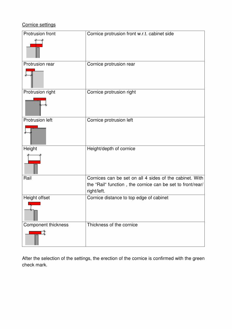
Cornice settings
Protrusion front
Cornice protrusion front w.r.t. cabinet side
Protrusion rear
Cornice protrusion rear
Protrusion right
Cornice protrusion right
Protrusion left
Cornice protrusion left
Height
Height/depth of cornice
Rail Cornices can be set on all 4 sides of the cabinet. With
the “Rail“ function , the cornice can be set to front/rear/
right/left.
Height offset
Cornice distance to top edge of cabinet
Component thickness
Thickness of the cornice
After the selection of the settings, the erection of the cornice is confirmed with the green
check mark.

Handbook SelectionProfessional
SelectionProf_Handbook_EN.pdf 135 / 143
6.14.4 Front panel functions
Selection procedure
Front panels can be fixed on the cabinets at required areas. In case of a tall unit, it can
be fixed both sideways as well as on the top (top filler panel).
If a tall unit needs to be fitted with a front oanel, it must be selected in the 3D view. It
should be selected exactly on the cabinet side edge (preferably outside).
The cabinet edge should
be selected exactly.
Side is selected
Front panel is placed
laterally
Select top panel, front panel
is placed on top

Front panel settings
Component height
Specifies height/width of the front panel
Component height Component height/width can also be
determined with the mouse. A point, on
which the component is attached, is
selected.
Indent
Specifies the indent dimension of the
front panel.
Protrusion front
Specifies protrusion front/top
Protrusion rear
Specifies protrusion rear/bottom
Front panel thickness
Specifies front panel thickness
After the selection of the settings, the erection of the front panel is confirmed with the
green check mark.
6.14.5 Visible sides functions
Selection procedure
The screen function can be used to replicate a certain component, e.g. a cabinet wall.
Subsequently the newly formed component can be modified.
For the visible side of base cabinet the outer cabinet wall is selected and then
replicated. Protrusions can be specified thereafter.
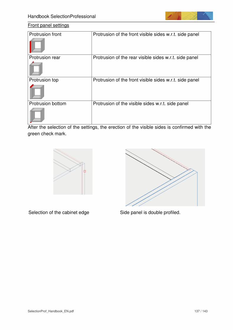
Handbook SelectionProfessional
SelectionProf_Handbook_EN.pdf 137 / 143
Front panel settings
Protrusion front
Protrusion of the front visible sides w.r.t. side panel
Protrusion rear
Protrusion of the rear visible sides w.r.t. side panel
Protrusion top
Protrusion of the front visible sides w.r.t. side panel
Protrusion bottom
Protrusion of the visible sides w.r.t. side panel
After the selection of the settings, the erection of the visible sides is confirmed with the
green check mark.
Selection of the cabinet edge Side panel is double profiled.

6.15 Material
6.15.1 Material selectionl
Fundamentals
Different materials and surfaces can be assigned to each cabinet and component
(plinth, work tops) in CAD.
They can also be displayed in colour and released in the bill of goods.
Material settings
The Assistant “Surfaces and material“can be started with the “Material“tab. The
selection can be done with “Material selection“.
Process of material selection:
1. Furniture or components, for which a material or surface should be assigned. 2. Select material category. 3. Select element for material allocation 4. Select surface 5. Determine grain direction
1) Cabinet selection One or more cabinets, which need to be coated with the surface, can be selected. The corresponding cabinet is selected with a cabinet edge. 2) Component selection An individual component is selected here, e.g. plinth, visible side or work top. Likewise, a single door or drawer for a front panel can also be selected. An individual side panel can also be selected. 3) Surface preview Displays the selected surfaces on the cabinet 4) Category The material category is selected here. This in turn influences the surface selection options. 5) Element selection The elements of a cabinet, which influence surface selection, are selected here. 6) Surface selection The desired surface is selected here.

Handbook SelectionProfessional
SelectionProf_Handbook_EN.pdf 139 / 143
Sample cabinet
Selection:
- Work top beech, grain long
- Left cabinet front beech, grain long
- Right cabinet, front beech light, grain diagonal
- Drawer front centre, colored red for component selection
- Visible sides, colored red for component selection

6.15.2 Color display of room / cabinet
Displays the cabinet in the selected surface.
Different settings can be undertaken in the dialog window.
Quality There are 3 quality levels
High / medium / outline
The setting influences the display speed and quality.
Render target Specifies the display position of furniture / room
layout
Display window > In the actual window
Render window > Own window
Using the render window permits the saving of the
displayed situation in different formats.
Illumination Brightness specification, optimal values lie in the 90-
100 range.
Values can be set individually. By clicking near the
value, further settings can be specified.
Brightness Brightness setting for the display
Contrast Display contrast settings
Centre tone With the setting
Outside light The value of this field should always be set to OFF
Edit background Off = background is white
On= standard background
Lights Lights should be set to “On“.

Handbook SelectionProfessional
SelectionProf_Handbook_EN.pdf 141 / 143
6.15.3 Concealed display / Light symbols
Hidden display ON Hidden display OFF
Light symbols ON Light symbols OFF
Displays the position of the light source. The light sources are automatically placed
according to the room size. They can be manually shifted to achieve a special light
effect. It is best to move the light symbol in the top view and only in the vertical and
horizontal position. The AutoCAD function F8 helps in achieving this movement. The
light symbol can be moved in a straight direction only.

6.16 Output
6.16.1 Wood- Bill of Materials
A detailled description of the function “Wood– Bill of Materials“ in Section 3.8.1.
6.16.2 Hettich order list
A detailled description of the function “Hettich Order list“ in Section 3.8.2.
6.16.3 Document manager
All components are dimensioned and displayed
This function is identical to the function “All components are dimensioned and
displayed“ in Designer. A detailled description in section 5 “Document manager“.
Carcase overview in the room
Through the link “carcase overview in room“, an overview of all the cabinets which are
used incl.the overview of the components which are to be added to the room planning
would be created.
Wood bill of items (Complete room)
Through the link “Wood Bill of Materials(Complete Room)“ found in the left in the
Assistant, a cumulative finished dimension list of all the components which are used in
the current room plan is created. Hereby all the cabinets which are used would be
considered together.
Wood bill of items (Individual cabinet)
Through the link “Wood Bill of Materials (individual cabinet)“ found in the left in the
Assistant, a cabinet based finished dimension list would be created. Hereby each
cabinet of the current room plan would be considered individually...
Hettich order list (Complete room)
Through the link “Hettich Order list (complete room)“ found in the left in the Assistant , a
cumulative order list of all the Hettich fittings used in the current room plan would be
created. Hereby all the cabinets which are used would be considered together.

Handbook SelectionProfessional
SelectionProf_Handbook_EN.pdf 143 / 143
Hettich order list (Individual cabinet)
Through the link “Hettich Order list (individual cabinet)“ found in the left in the Assistant,
a cabinet based order list of the Hettich fittings which are used would be created.
Hereby each cabinet of the current room plan would be considered individually.
6.17 Examples
A comprehensive example is available in the document SelectionProf_Training
exercises_EN.PDF.


