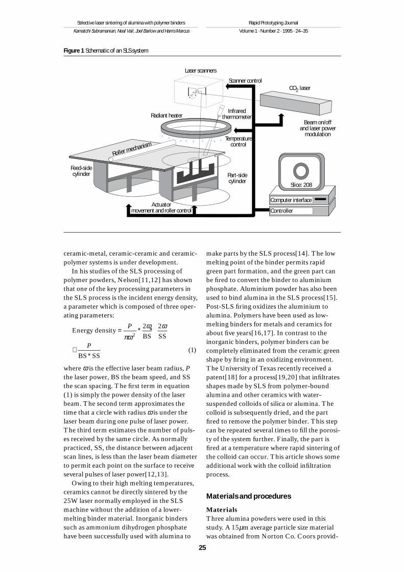
Selective laser sintering (SLS) is one of severalapproaches to the solid freeform fabrication(SFF) of ceramics. SFF is the production offreeform solid objects directly from computermodels without part-specific tooling orhuman intervention[1,2]. Other SFF tech-niques for low-density ceramic fabricationinclude the multijet solidification (MJS)process[3], laminated object manufacturing(LOM)[4], fused deposition modelling(FDM)[5], 3D printing[6], and directed lightfabrication[7]. The SLS process[8-10] uses aCAD solid model file to define the object tobe produced. This file is sliced into mathe-matical layers that represent the cross-sectionof the part. The layer information is used tocontrol a laser scanner/controller that directs a25W CO2 laser beam (λ = 10.6µm) to repro-duce the mathematical layer by selectivelysintering or fusing polymer powder. Typicallayer thicknesses are controlled to lie in the75-125µm range. The University of TexasSLS machine, used in this study, is similar tothe DTM Corporation Model 125 SLSmachine in the laser power employed and inthe manner by which powder layers are pro-duced. Two cylinders, a part cylinder inwhich the part is fabricated and a powder feedcylinder, are used (see Figure 1). After a layerhas been selectively sintered, a piston in thebottom of the feed cylinder is raised to supplypowder for the next layer, and the piston inthe bottom of the part cylinder is correspond-ingly lowered. The powder from the feedcylinder is spread on the surface of the partcylinder by a translating, counter-rotatingroller. The cycle is then repeated until thepart is completed. Typical vertical build ratesfor processing polymer/ceramic powders is10-2m/hr for a part with a square cross-section (0.1m × 0.1m). The SLS of polymershas been commercialized by DTM Corpora-tion while the SLS of metals, metal-polymer,
24
Selective lasersintering of aluminawith polymer binders
Kamatchi Subramanian,Neal Vail,Joel Barlowand Harris Marcus
The authorsKamatchi Subramanian, Neal Vail, Joel Barlow andHarris Marcus are all based in the Center for MaterialsScience and Engineering, The University of Texas at Austin,Austin, Texas, USA.
AbstractThe selective laser sintering (SLS) process is used toprepare test bars from Al2O3/polymer binder powders.Finds that binder-coated Al2O3 particles formed bars thatwere approximately twice as strong as could be formedfrom mixtures of alumina and polymer binder at the samebinder level and processing conditions. In mixed systems,bar strengths increased nearly in proportion to increases inpolymer binder content over the 20-40 per cent volumebinder range. Parts made in any particular laser scanningmode showed optimum values for strength and density asthe laser energy density was systematically increased from2-8cal/cm2. Suggests that optima result from the counter-acting influences of energy density on binder fusion andthermal degradation. The optimum energy density is modeor geometry sensitive and shifts to lower values as thelaser scanning vector is reduced. Concludes that thisbehaviour is probably the result of the lower heat losses.Equivalently better utilization of laser energy is associatedwith the shorter scan vectors. Some of the SLS fabricatedbars were infiltrated with colloidal alumina, fired toremove the binder, and sintered at 1,600˚C to achievealumina bars with 50 per cent relative densities, intercon-nected porosity, and strengths between 2 and 8MPa.
The authors gratefully acknowledge partial
financial support of this work through ARPA/ONR
Grant No. N00014-92-J-1394 and the Texas on of
alumina Advanced Technology Program through
Grant No. ATP-351. The assistance of Dr A.
Manthiram with TGA measurements, of Mr B.
Hart, Golden Technologies, with agglomeratipow-
der, and of Mr Suman Das with creation of part
files is also gratefully acknowledged.
ceramic-metal, ceramic-ceramic and ceramic-polymer systems is under development.
In his studies of the SLS processing ofpolymer powders, Nelson[11,12] has shownthat one of the key processing parameters inthe SLS process is the incident energy density,a parameter which is composed of three oper-ating parameters:
where ω is the effective laser beam radius, Pthe laser power, BS the beam speed, and SSthe scan spacing. The first term in equation(1) is simply the power density of the laserbeam. The second term approximates thetime that a circle with radius ω is under thelaser beam during one pulse of laser power.The third term estimates the number of puls-es received by the same circle. As normallypracticed, SS, the distance between adjacentscan lines, is less than the laser beam diameterto permit each point on the surface to receiveseveral pulses of laser power[12,13].
Owing to their high melting temperatures,ceramics cannot be directly sintered by the25W laser normally employed in the SLSmachine without the addition of a lower-melting binder material. Inorganic binderssuch as ammonium dihydrogen phosphatehave been successfully used with alumina to
make parts by the SLS process[14]. The lowmelting point of the binder permits rapidgreen part formation, and the green part canbe fired to convert the binder to aluminiumphosphate. Aluminium powder has also beenused to bind alumina in the SLS process[15].Post-SLS firing oxidizes the aluminium toalumina. Polymers have been used as low-melting binders for metals and ceramics forabout five years[16,17]. In contrast to theinorganic binders, polymer binders can becompletely eliminated from the ceramic greenshape by firing in an oxidizing environment.The University of Texas recently received apatent[18] for a process[19,20] that infiltratesshapes made by SLS from polymer-boundalumina and other ceramics with water-suspended colloids of silica or alumina. Thecolloid is subsequently dried, and the partfired to remove the polymer binder. This stepcan be repeated several times to fill the porosi-ty of the system further. Finally, the part isfired at a temperature where rapid sintering ofthe colloid can occur. This article shows someadditional work with the colloid infiltrationprocess.
Materials and procedures
MaterialsThree alumina powders were used in thisstudy. A 15µm average particle size materialwas obtained from Norton Co. Coors provid-
Energy densityBS SS
BS SS
= ∗ ∗
≅∗
P
Pπω
ω ω2
2 2
1( )
25
Selective laser sintering of alumina with polymer binders
Kamatchi Subramanian, Neal Vail, Joel Barlow and Harris Marcus
Rapid Prototyping Journal
Volume 1 · Number 2 · 1995 · 24–35
Figure 1 Schematic of an SLS system
Temperaturecontrol
Radiant heater
Laser scanners
Scanner control
Infraredthermometer
Part-sidecylinder
Feed-sidecylinder
Actuatormovement and roller control
Beam on/offand laser power
modulation
Slice: 208
Roller mechanism
Computer interface
Controller
CO2 laser
ed a 2µm powder (AD995 – 99.5 per centAl2O3) and a 5µm powder (AD85 – 85 percent Al2O3/15 per cent SiO2). As received, the5µm powder was agglomerated into 100µmparticles. Little agglomeration was observedin the other two powders.
Two polymer binders, poly(methylmethacrylate), PMMA, and a copolymer,poly(methyl methacrylate-co-n-butylmethacrylate) were used. These materialswere prepared as water-based emulsions, usingthe procedures described elsewhere[21]. ThePMMA binder had a melt flow index of31g/10 min., measured following ASTMD1238 at 200˚C with an extrusion pressure of0.52MPa. The melt flow index of the copoly-mer binder is 11.6g/10 min. The softening orglass transition temperatures for these amor-phous materials were measured to be 104˚Cand 87˚C for PMMA and copolymer respec-tively, by a Perkin-Elmer DSC-7 DifferentialScanning Calorimeter, operated at a10˚C/min. scan rate. These binder propertiesgive near optimum performance for spraycoating and particulate binding[21]. Theflexural strength in three-point bending of thePMMA binder is 21 ± 3MPa and that for thecopolymer is 35 ± 5MPa[22]. The monomerscomprising these polymer binders were chosen because they cause the polymer todepolymerize thermally[22-24] when thepolymer is exposed to temperatures in excessof 400˚C. Thermal depolymerization of thebinder is preferred over other polymer degra-dation mechanisms because little or no car-bonaceous residue is generated.
Two colloids were used to infiltrate SLSfabricated specimens. Alumina sol A (VistaChemicals 18N420) contained 12 per centsolids and had a vendor-specified 60nm parti-cle size. Alumina sol B (Vista Chemicals14N425) had a vendor-specified 150nmparticle size and contained 16 per cent solids.The solids’ contents were determined for bothsols by drying a portion of each sol at 120˚Cfor 24 hours.
Powder processing and coatingTo examine the potential benefits of simplymixing powdered binder with alumina, poly-mer powders were prepared by spray dryingthe aqueous polymer emulsion in an AnhydroLaboratory Spray Drier 1. The drier is typi-cally operated at an emulsion flow rate near100ml/min., atomizer speed near 3 × 10⁴rpm,inlet air temperature near 250˚C, and a 90-
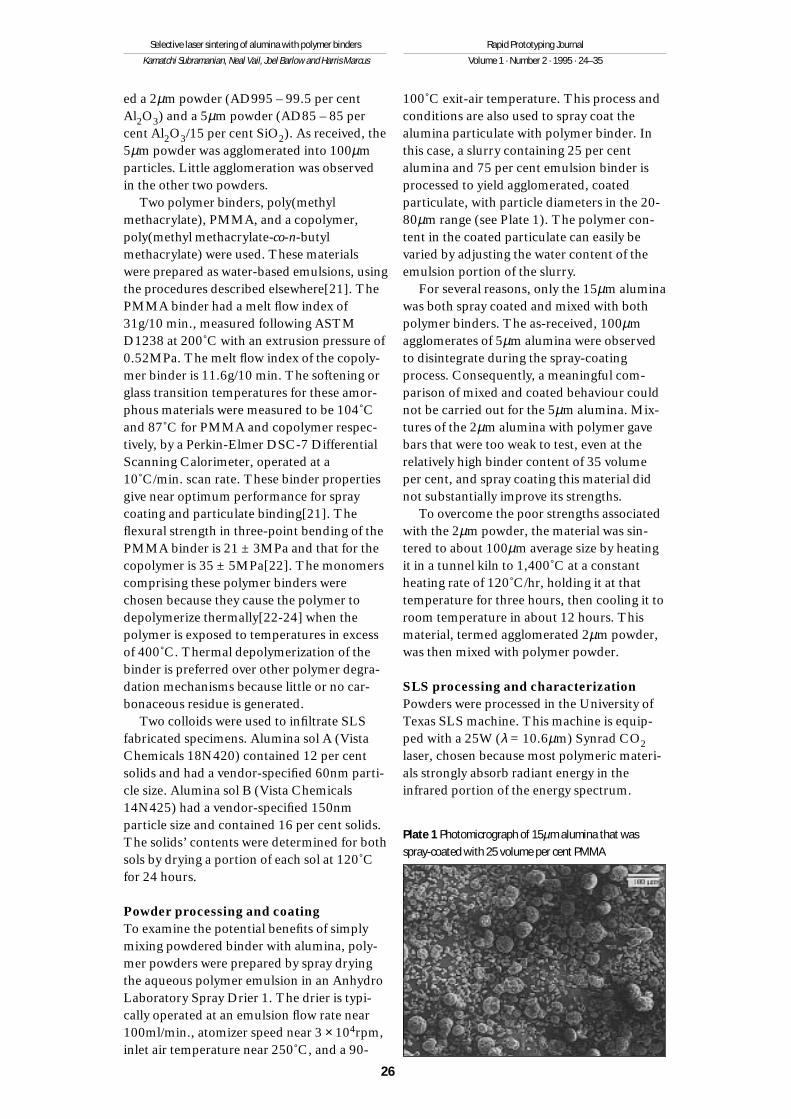
100˚C exit-air temperature. This process andconditions are also used to spray coat thealumina particulate with polymer binder. Inthis case, a slurry containing 25 per centalumina and 75 per cent emulsion binder isprocessed to yield agglomerated, coatedparticulate, with particle diameters in the 20-80µm range (see Plate 1). The polymer con-tent in the coated particulate can easily bevaried by adjusting the water content of theemulsion portion of the slurry.
For several reasons, only the 15µm aluminawas both spray coated and mixed with bothpolymer binders. The as-received, 100µmagglomerates of 5µm alumina were observedto disintegrate during the spray-coatingprocess. Consequently, a meaningful com-parison of mixed and coated behaviour couldnot be carried out for the 5µm alumina. Mix-tures of the 2µm alumina with polymer gavebars that were too weak to test, even at therelatively high binder content of 35 volumeper cent, and spray coating this material didnot substantially improve its strengths.
To overcome the poor strengths associatedwith the 2µm powder, the material was sin-tered to about 100µm average size by heatingit in a tunnel kiln to 1,400˚C at a constantheating rate of 120˚C/hr, holding it at thattemperature for three hours, then cooling it toroom temperature in about 12 hours. Thismaterial, termed agglomerated 2µm powder,was then mixed with polymer powder.
SLS processing and characterizationPowders were processed in the University ofTexas SLS machine. This machine is equip-ped with a 25W (λ = 10.6µm) Synrad CO2laser, chosen because most polymeric materi-als strongly absorb radiant energy in theinfrared portion of the energy spectrum.
26
Selective laser sintering of alumina with polymer binders
Kamatchi Subramanian, Neal Vail, Joel Barlow and Harris Marcus
Rapid Prototyping Journal
Volume 1 · Number 2 · 1995 · 24–35
Plate 1 Photomicrograph of 15µm alumina that wasspray-coated with 25 volume per cent PMMA
Powder layer thickness was kept constant at175µm for all experiments. The scan linespacing, SS, was varied between 75-125µm,the beam speed was varied between 30-150cm/sec., and the laser power was variedbetween 6-14W to vary the energy densitybetween 2-8 cal/cm2, as calculated by equa-tion (1). The powder bed was maintained at80˚C when processing powders containingthe copolymer, and at 90˚C when processingpowders containing the PMMA to minimizewarpage and curl[5,25,26].
Test specimens, 0.076m × 0.025m ×0.00625m, suitable for measurement of three-point bend strengths, were made by SLS infour orientations with respect to the laserbeam scanning direction (see Figure 2). Somespecimens, shaped from agglomerated 2µmpowder mixed with copolymer binder, werealso processed with layers that were alternate-ly scanned with orientations (i) and (ii) inFigure 2. Bend strengths were measured atroom temperature with an Instron testingmachine, operated at a cross-head speed of2mm/min.
The polymer content of some SLS-fabricat-ed specimens was determined with a Perkin-Elmer System 7 Thermogravimetric Analyzer(TGA), operated at a scan rate of 40˚C/min. innitrogen. Small samples, typically 100mg,were removed near the centre of three-pointbend specimens. These were crushed to pow-der prior to testing in the TGA.
Post-processing proceduresOnly parts shaped from agglomerated 2µmpowder mixed with 20 per cent volume
copolymer powder were post-processed. TheSLS-fabricated test specimens were infiltratedby simply immersing them in the alumina solat room temperature. After infiltration, thespecimens were dried in an air oven for 24hours at 120˚C. The infiltrated parts werethen heated at 50˚C/hr to 600˚C, where theywere held for approximately 12 hours todecompose the binder thermally. Afterdebinding, the specimens were heated at3.3˚C/min. to 1,050˚C and held for six hoursto sinter the nano-sized alumina particles,followed by cooling at about 2˚C/min. toroom temperature. The samples were thenplaced in an MoSi2 furnace, where they wereheated at 5˚C/min. to 800˚C, then at 2˚C/min.to 1,600˚C, where they were held for sixhours, prior to cooling to 800˚C at 2˚C/min.The samples were measured and weighedbefore and after the debinding and high-temperature sintering operations.
Results and discussion
Figures 3-12 show bend strength and densityof green samples made by SLS from thesealumina-polymer formulations. Figure 3shows bend strengths of green bars madefrom 25 per cent volume copolymer-coated15µm alumina at two different laser scanningdirections. This comparison of strengthsclearly shows a geometric or scan directiondependency that is not determined by theenergy density, equation (1), alone. Depen-dency of strength on scan geometry is alsoseen in other experiments (see Figures 8-10and 12), and seems to be a general feature ofpolymer-bound ceramic[22] and metal[27]systems. Generally, improved strengths areobtained at lower energy density values whenthe scan vectors are shorter, as can be seen bycomparing the curves in each of the Figures 3,8-10 and 12. This behaviour is believed to becaused by higher average temperatures in theparts made with shorter scans[22], owing toless time being available between input energypulses for heat losses by radiation and convec-tion. Higher average temperatures can lead tolower binder viscosity and higher flow ofpolymer binder. Flow and wetting of thebinder is considered critical to achieving goodgreen strengths, as recently demonstrated inan article on binder design[21]. Plate 2 showsa good example of binder flow.
The dependency of green strength onenergy density for a particular scan geometry
27
Selective laser sintering of alumina with polymer binders
Kamatchi Subramanian, Neal Vail, Joel Barlow and Harris Marcus
Rapid Prototyping Journal
Volume 1 · Number 2 · 1995 · 24–35
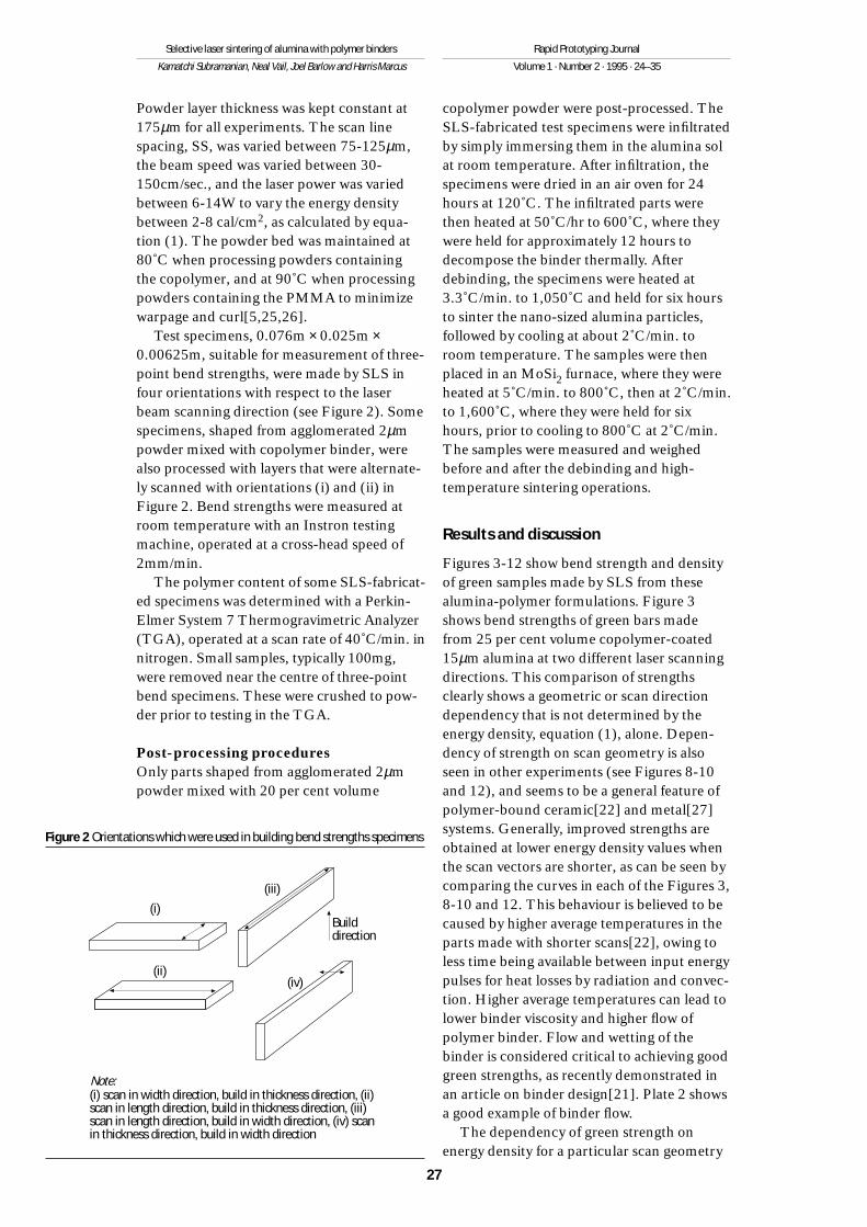
Figure 2 Orientations which were used in building bend strengths specimens
(i)
(ii)
Builddirection
(iii)
(iv)
Note:(i) scan in width direction, build in thickness direction, (ii)scan in length direction, build in thickness direction, (iii)scan in length direction, build in width direction, (iv) scanin thickness direction, build in width direction
is qualitatively consistent from test to test, ascan be seen by comparing Figures 3, 5, 6, 8-10 and 12. At initially low energy density,strength is low, probably because layer-to-layer fusion is incomplete[12,22]. Suchbehaviour is also seen in PMMA-coated SiCmaterials[13]. As the energy density is in-creased, fusion is improved and strengthincreases. The increase is generally non-linear, however, and optimum strengths areoften seen with increasing energy density in aparticular scan mode.
28
Selective laser sintering of alumina with polymer binders
Kamatchi Subramanian, Neal Vail, Joel Barlow and Harris Marcus
Rapid Prototyping Journal
Volume 1 · Number 2 · 1995 · 24–35
Figure 3 Effects of energy density and scan direction onbend strength of samples made from 25 per cent volumecopolymer-coated 15µm alumina
2
1.5
1
0.5
02 3 4 5 6 7 8
Condition (i)
Bend strength, MPa
Energy density, cal/cm2
Condition (ii)
Figure 4 Polymer content after SLS processing of somesamples in Figure 3
0 2 4 6 8 10
Polymer content (per cent)10
8
6
4
2
0
Condition (i)
Energy density, cal/cm2
Condition (ii)
Figure 5 Effects of energy density and binder content onstrength of samples made from 5µm alumina mixed withPMMA
1.8
1.4
1
0.6
0.21 2 3 4 5 6
Condition (i)
Bend strength, MPa
Energy density, cal/cm2
20 per cent volume30 per cent volume40 per cent volume
PMMA contentKey:
Figure 6 Comparison of strengths of bars made fromspray-coated and mixed binders (25 per cent volumePMMA/75 per cent volume 15µm alumina composition)
0.6
0.5
0.4
0.3
0.2
0.1
02.5 3 3.5� 4 4.5 5 5.5 6
Bend strength, MPa
Energy density, cal/cm2
Spray-coated
Mixed
Plate 2 Fracture surface of infiltrated and fired part madefrom agglomerated 2µm alumina
The reason for the optimum in green strengthwith energy density is suggested by comparingFigures 3 and 4. Figure 4 shows that, as theenergy density increases much beyond4cal/cm2 for bars scanned either across thewidth (condition (i)) or across the length(condition (ii)), the polymer binder is reducedfrom the 8.5 per cent coated on the particlesto as low as 0.5 per cent at 8 cal/cm2 (condi-tion (i)). These observations suggest that thebinder is degrading and evaporating at thesurface temperatures generated by the laserbeam. The shorter scan vectors (condition(i)) appear to cause more binder evaporationthan the longer vectors (condition (ii)) at the
same energy density, as expected from theconclusion above that shorter scan vectorslead to higher surface temperatures and fromthe published rates of depolymerization thatshow rapid increases in rate with increasingtemperature[22,23]. The optimum in greenstrengths (Figure 3) occurs at 4cal/cm2 forcondition (i) and at 6cal/cm2 for condition(ii). These approximately coincide with theonset of measurable polymer depolymeriza-tion (a reduction in polymer content to about8 per cent) in Figure 4. Consequently, itseems reasonable to conclude that the decline
29
Selective laser sintering of alumina with polymer binders
Kamatchi Subramanian, Neal Vail, Joel Barlow and Harris Marcus
Rapid Prototyping Journal
Volume 1 · Number 2 · 1995 · 24–35
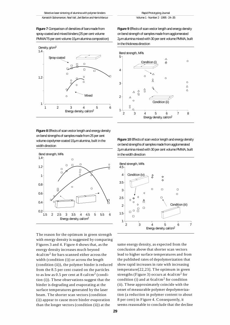
Figure 9 Effects of scan vector length and energy densityon bend strength of samples made from agglomerated2µm alumina mixed with 30 per cent volume PMMA, builtin the thickness direction
5
4
3
2
12 3 4 5 6 7 8
Bend strength, MPa
Energy density, cal/cm2
Condition (ii)
Condition (i)
Figure 10 Effects of scan vector length and energy densityon bend strengths of samples made from agglomerated2µm alumina mixed with 30 per cent volume PMMA, builtin the width direction
2 3 4 5 6 7
4.5
4
3.5
3
2.5
2
1.5
1
Bend strength, MPa
Condition (iii)
Condition (iv)
Energy density, cal/cm2
Figure 7 Comparison of densities of bars made fromspray-coated and mixed binders (25 per cent volumePMMA/75 per cent volume 15µm alumina composition)
1.4
1.2
11 2 3 4 5 6
Density, g/cm3
Energy density, cal/cm2
Spray-coated
Mixed
Figure 8 Effects of scan vector length and energy densityon bend strengths of samples made from 25 per centvolume copolymer-coated 15µm alumina, built in thewidth direction
1.4
1.2
1
0.8
0.6
0.4
0.21.5 2 2.5 3 3.5 4 4.5 5 5.5 6
Bend strength, MPa
Energy density, cal/cm2
in strength as energy density is increasedbeyond the optimum is a consequence ofbinder degradation at the higher temperaturesgenerated in that particular scan mode.
The influence of binder concentration ongreen strengths is shown in Figure 5 for 5µmalumina mixed with PMMA. Generally, greenstrength increases with increasing bindercontent, approaching 1.6MPa at 40 per centvolume binder. Optimum strengths withrespect to energy density are again seen, andthe optimum strengths appear to shift towardshigher energy density values as the polymercontent is increased. These results are consis-
tent with the conclusions above that optimumstrengths occur when the additional wettingand flow caused by further raising the localtemperature is offset by destruction andevaporation of the binder. Since the polymeris selectively heated by the infrared laserbeam, the energy density required to heat the polymer to achieve optimum strength issimply lower at lower binder concentrationsbecause there is less polymer to heat.
The additional observation from Figure 5that low binder concentrations lead to lowgreen strengths could be related to the relativeimportance of the statistical probability offorming bonds between particles in mixedsystems. If equal-sized particles are placedrandomly on a fixed lattice, the probability offinding a particle of type (i) is just φi, the areafraction (or volume fraction) of sites occupiedby (i) in the lattice, and the probability thattwo adjacent sites contain the same type (i) isjust φi
2. With 1 corresponding to alumina and2 corresponding to polymer, the strength ofthe system could empirically be written as:
S = σ1φ12 + σ2φ2
2 + σ12φ1φ2 (2)
where S is the “composite” strength, σ1 thestrength of interactions between aluminaparticles, σ2 the strength of interactionsbetween polymer particles and σ12 thestrength of the alumina-polymer interactions;σ1 ≅ 0 because the alumina powder does notadhere to itself at low temperatures. Equation(2) then reduces to:
S = σ2φ22 + σ12 + σ12φ1φ2
(3)≅ σφ2(φ1 + φ2) = σ φ2
provided the two strengths, σ2 and σ12, arealso comparable in size and equal to σ. Thislast criterion may seem a bit artificial, how-ever a study by Vail[22] indicates that mostfracture surfaces show mixed modes of fail-ure, that is both cohesive and adhesive failureoccurs for these binders on a wide range ofinorganic surfaces including alumina. Thissuggests that the interfacial and cohesivestrengths are comparable for these binders. Atany rate, equation (3) suggests that the greenstrength should vary in proportion to thevolume fraction of binder, all other influencesbeing negligible. With reference to Figure 5, acomparison of the strengths of the 30 per centvolume to the 40 volume per cent materials, atfixed energy density, seems to follow equation(3) within the experimental uncertainty of themeasurements. Even the strengths of the 20
30
Selective laser sintering of alumina with polymer binders
Kamatchi Subramanian, Neal Vail, Joel Barlow and Harris Marcus
Rapid Prototyping Journal
Volume 1 · Number 2 · 1995 · 24–35
Figure 11 Effects of energy density and scan vectorlengths on densities of samples made from agglomerated2µm alumina mixed with 20 per cent volume copolymer,built in the thickness direction
Density, g/cm3
Energy density, cal/cm2
Width
Length
Percentage theoretical density1.6
1.5
1.4
1.3
1.22 3 4 5 6 7 8�
Mixed46.9
42.5
38.1
Figure 12 Effects of energy density and scan vectorlengths on strengths of samples made from agglomerated2µm alumina mixed with 20 per cent volume copolymer,built in the thickness direction
4
3
2
1
01 3 6 7 9
Bend strength, MPa
Energy density, cal/cm2
Length
Width Mixed
per cent volume binder containing materialsare about half those of the 40 per cent volumematerials, provided the comparison is restrict-ed to near the optimum in the 20 per centvolume case, where the amount of polymer isaccurately known.
Figure 6 shows another comparison thathelps to verify equation (3). Here, the bendstrengths of coated versus mixed powders arecompared at the same volume fraction ofbinder for 15µm alumina and PMMA. Thebend strengths of the spray-coated powdersare three to four times those of the mixedpowders at the same binder volume fraction.From the perspective of probability, thebinder-coated alumina powders all have aprobability for interaction of binder with itselfor with the alumina of 1.0, so that equation(3) should reduce to just S = σ. The strengthparameter, σ, clearly varies with energy densi-ty, however if one assumes equation (3) tohold for the mixed system, with equation (3)evaluated from the observed strength of themixed powder, one can make a fair estimate ofthe strength of the mixed powder system,processed at the same energy density.
Clearly, more work needs to be done tosort out and quantify the contributing factorsto green strength in both the mixed and coated systems of polymer binder with inor-ganic particles, and the model (equations (1-3)) has to be considered as very tentative,and probably over-simplistic. The processedbars, first of all, are porous. Figure 7 shows anexample of the effect of energy density on partdensity. Spray-coated particles appear to packbetter than the mixed particles, and densitiesof parts that are made from the spray-coatedmaterials change much less with variations inenergy density as compared with mixed ma-terials. This difference has been seen in sever-al systems and is one of the primary reasonsfor spray coating. Typical green part porosi-ties range from 50-60 per cent for a variety ofspray-coated powders, with mean inorganicparticulate diameters ranging between 3 and13µm[22]. Nonetheless, porosity certainlyaffects strength, and should be factored into amore complete consideration of the issuesaffecting bending strength. In numeroussystems[28,29], equations of the form:
σ = σ0 (1 – ε)n (4)
where σ0 is a solid strength, ε the porosity,and n an empirical coefficient, are commonlyused. The form of equation (4) and the
changes in density and strength of the coatedmaterial (Figures 6 and 7), suggest that thevariability in σ with energy density is reallycaused by a variation in σ with density. Unfor-tunately, the data are too badly scattered andover too narrow a range to permit the accuratedetermination of n and σ0.
Specimens were made in the four orienta-tions described in Figure 2 of agglomerated2µm alumina that was mixed with 30 per centvolume spray-dried copolymer (Figures 9 and10). Maximum green strengths were muchhigher (3-5MPa versus 0.5-1.5MPa) thanwere achieved in either the mixed or coated15µm alumina system (Figures 3, 6, and 8).One reason is the higher binder content (30per cent volume) that could, via equation (3),cause a strength increase of approximately 20per cent, over the 25 per cent volume bound15µm material. The primary reason, however,appears to be related to the very differentaverage particle sizes (100µm for the agglom-erated alumina). Larger particles have beenshown to give higher bend strengths in barsmade from glass and silicon carbide[22],where, for example, doubling the averageparticle size appears to double the strength.One theory[22] suggests that the strength ishigher because the cross-sectional area of thepolymer neck formed between the particles isproportional to the particle diameter. Thedetails of this theory are presently being pre-pared for publication.
Lower binder contents are desirable be-cause porosity of the fired object is propor-tional to the binder content. The higherstrengths shown by the agglomerated aluminasystem, above, permitted lowering the bindercontent to 20 per cent volume. Figures 11 and12 show the effects of scan orientation ondensity and strength, respectively. As in theother cases discussed previously, the strengthsshow optima with respect to energy density,and these optima occur at lower values ofenergy density when the scan vectors areshorter. One interesting feature of this work isthe introduction of layers that are alternatelyscanned in the width and length directions.The strengths and densities of parts madefrom alternately scanned layers are betweenthose made by scanning only in the length orwidth direction, as expected.
Only parts made from agglomerated 2µmpowder mixed with 20 per cent volumecopolymer binder (Figures 11 and 12), werepost-processed. The reason for this choice
31
Selective laser sintering of alumina with polymer binders
Kamatchi Subramanian, Neal Vail, Joel Barlow and Harris Marcus
Rapid Prototyping Journal
Volume 1 · Number 2 · 1995 · 24–35
was the expectation that the 2µm componentsof the agglomerates would have the best chanceof sintering to high density in a reasonabletime[29,30]. The details of the post-processingtreatment are described earlier in this article.Here, we simply add a few comments andobservations.
The infiltration process described aboveneeds to be optimized. For example, the weightgain after drying ranged from 2-12 per cent,with a great deal of scatter and no obviousdependency on the colloid sol used. In a fewcases, reinfiltration of dried specimens wasattempted: however, it was unsuccessful. Partof the reason for this problem may be that thesurface tension of the sol is too high. This hasbeen adjusted in silica sols[18-20] and withother infiltrants[31] by the addition of alcoholsto the sol. Despite this problem, all of thesintered bodies held their shapes duringdebinding. Even 2 per cent colloid seems to bebeneficial.
The heating rate at which we debind(50˚C/hr) is far higher than the 2-3˚C/hr ratesused to remove thermally polymer binders thatare used in conventional metal injection mould-ing (MIM) and ceramic injection moulding(CIM) processes[32-35]. The reason that wecan do this without cracking the parts is proba-bly related to the inherent interconnectedporosity of green and sintered parts made bythe SLS process [13,18-20,30,35]. The pres-ence of this porosity provides pathways forexpanded polymer and decomposition gases toleave the structure without generation of inter-nal stress. Plate 3 shows a fracture surface of agreen part that suggests a long-scale, continu-ous porosity.
The weight loss due to polymer removalalone is expected to be 7.6 per cent for thesystem described above. Losses that range
between 7 per cent and 10 per cent, indepen-dent of the colloid sol used, are observed afterdebinding and sintering. The additional loss ofmass probably corresponds to water that wasbound with the colloid after drying at 120˚C.
The samples undergo some limited densifi-cation during sintering. Figure 13 shows linearshrinkage, relative to the green part, afterinfiltration, debinding and sintering at 1,600˚C,to be about 13 ± 2 per cent. Shrinkage is uni-form in the build plane, corresponding to thelength and width directions, and slightly higherin the thickness direction, perpendicular to thebuild plane. This behaviour is consistent withthat seen in other post-processed polymerpowder[36], composite powder[37], and metalpowder[38] experiments, and probably is theresult of the inability of the SLS process with itssteep thermal gradients to produce uniformdensity across the thickness of the buildlayer[12,13].
Final sintered densities of the infiltratedmaterials are shown in Figure 14 to be largelyindependent of energy density, as expected.The density of parts infiltrated with colloid B isslightly higher than that of parts infiltrated withcolloid A, despite the fact that the particles ofcolloid B are larger and should sinter less thanthose of A under the same conditions. Theapparently important feature of these colloidsols under the firing conditions used in thisstudy is not particle size but solids content.Given that the porosities of the green parts are
32
Selective laser sintering of alumina with polymer binders
Kamatchi Subramanian, Neal Vail, Joel Barlow and Harris Marcus
Rapid Prototyping Journal
Volume 1 · Number 2 · 1995 · 24–35
Plate 3 Fracture surface of an SLS green part made fromagglomerates of 5µm alumina mixed with PMMA
Figure 13 Shrinkage in sintered samples that wereinfiltrated with colloid A prior to firing
20
18
16
14
12
102 3 4 5
Percentage linear shrink
Energy density, cal/cm2
LengthThicknessWidth
Key:
all nearly the same, colloid B sol with 16 percent solids simply deposits more material in thepores of the green part than does colloid A,which has only 12 per cent solids. Plate 2 showsthe microstructure of a fracture surface inmaterial made from the infiltration and firing of100µm agglomerates of 2µm alumina. Thelarge agglomerates are still intact; however,close inspection reveals small sockets of “lacy”material which are believed to be sinteredcolloid. This material is seen throughout thearea of the photomicrograph, indicating thatinfiltration could be uniform. Strength ofinfiltrated and fired specimens ranged from 2-8MPa. Owing to scatter in the data, no obvioustrends with processing variables were noted.
Summary and conclusions
The effects of SLS process parameters, energydensity, part orientation, scan vector length,and powder compositions and conformations(mixed versus coated) on the densities and bedstrengths of green bars have been studied. For aparticular geometry with fixed scan vectorlength, energy density gives a reasonable quali-tative measure of energy input to the partsurface. Generally, green strengths areobserved to increase initially as energy densityis increased, to go through a maximum, thendecrease as energy density is further increased.The energy density that corresponds to themaximum in strength is seen to be a function ofboth polymer content and vector scan length.These dependencies are consistent with theexperimentally observed decrease in binder
content caused by thermal degradation of thebinder at high temperatures. At fixed energydensity, shorter scan vectors lead to highersurface temperatures and increased loss ofpolymer. Thus the maximum strength occurs atlower energy density values when shorter scanvectors are employed. Higher concentrations ofpolymer binder cause the maximum in strengthto shift to higher values of energy density,because more polymer is present that must beheated in order to flow and bind and perhapsbecause higher losses of binder can be toleratedat the initial higher concentrations withoutnoticeable strength reduction.
Green parts that are made from spray-coated powder always have higher strengthsthan parts made from mixed powders of binderand alumina at the same composition. A sim-plistic probability argument is presented thatattempts to explain this finding. It seems toprovide a semi-quantitative prediction of theincreases in strength observed with increasingbinder content and with spray coating.
Consistent with other studies, green strengthis observed to decrease to unusable values asthe alumina particle size is decreased to near2µm . The reasons for this behaviour are nottotally elucidated but may be related to theflowing binder neck size that is proportional tothe particle diameter. Greatly improvedstrength can be achieved by thermally sinteringthe 2µm particles into 100µm agglomeratesprior to coating, or mixing them with binder.
SLS-fabricated green parts have a porositywhich is quite similar to that of the powder bedfrom which they are formed. This porosity ishighly interconnected. This permits debindingrates that are rapid relative to those used inCIM or MIM processes. Interconnected poros-ity also permits infiltration of colloids into thepolymer-bound structure, prior to debinding.Infiltration of small quantities of aluminacolloids were found to improve the partstrength greatly during debinding and sinter-ing. These results are consistent with otherinfiltration studies[18-20].
References
1 Bourell, D.L., Beaman, J.J., Marcus, H.L. and Barlow,J.W., “Solid freeform fabrication, an advanced manu-facturing approach”, in Beaman, J.J., Marcus, H.L.,Bourell, D.L. and Barlow, J.W. (Eds), Proceedings of theSolid Freeform Fabrication Symposium, August 6-8,1990, The University of Texas at Austin, Austin, TX,1990, pp. 1-7.
33
Selective laser sintering of alumina with polymer binders
Kamatchi Subramanian, Neal Vail, Joel Barlow and Harris Marcus
Rapid Prototyping Journal
Volume 1 · Number 2 · 1995 · 24–35
Figure 14 Densities of fired samples
2.3
2.2
2.1
2.0
1.92 2.5 3 3.5 4 4.5 5
Sintered density, g/cm3
Energy density, cal/cm2
Colloid AColloid B
Key:
2 Marcus, H.L., Beaman, J.J., Barlow, J.W. and Bourell,D.L., “From computer to component in 15 minutes:the integrated manufacture of three-dimensionalobjects”, Journal of Metals, Vol. 42, pp. 8-11.
3 Gruel, M., Sindel, M. and Geiger, M., “Multiphase jetsolidification (MJS) – a new rapid prototype processfor metal and ceramic parts”, in Dickens, P.M. (Ed.),Proceedings of the 3rd European Conference on RapidPrototyping and Manufacturing, July 6-7, 1994,Nottingham University, Nottingham, 1994, pp. 257-60.
4 Griffin, D., Daufenbach, J. and McMillan, S., “Solidfreeform fabrication of functional ceramic compo-nents using a laminated object manufacturing tech-nique”, in Marcus, H.L., Beaman, J.J., Barlow, J.W.,Bourell, D.L. and Crawford, R.H. (Eds), Proceedings ofthe Solid Freeform Fabrication Symposium, August 8-10, 1994, The University of Texas at Austin, Austin, TX,1994, pp. 50-6.
5 Calvert, P., Crockett, R., Lombardi, J., O’Kelly, J. andStuffle, K., “Extrusion methods for solid freeformfabrication”, Proceedings of the Solid FreeformFabrication Symposium, August 8-10, 1994, The University of Texas at Austin, Austin, TX, 1990, pp. 50-6.
6 Cima, M.J. and Sachs, E.M., “Three dimensionalprinting: form, materials and performance”, inMarcus, H.L., Beaman, J.J., Barlow, J.W., Bourell, D.L.and Crawford, R.H. (Eds), Proceedings of the SolidFreeform Fabrication Symposium, August 12-14,1991, The University of Texas at Austin, Austin, TX,1991, pp. 187-94.
7 Studt, T., R&D Magazine, May 1994, pp. 55-7.
8 Deckard, C.R. and Beaman, J.J., “Solid freeformfabrication and selective powder sintering”, Proceed-ings of the 15th North American Conference onManufacturing Research, May 27-29, 1987, Society ofManufacturing Engineers, Dearborne, MI, 1987, pp. 636-40.
9 Deckard, C.R., “Part generation by layer-wise selectivelaser sintering”, MSc thesis, The University of Texas atAustin, Austin, TX, 1986.
10 Deckard, C.R., “Selective laser sintering”, PhDdissertation, The University of Texas at Austin, Austin,TX, 1988.
11 Nelson, J.C., “Selective laser sintering: a definition ofprocess and an empirical sintering model”, PhDdissertation, The University of Texas at Austin, Austin,TX, 1993.
12 Nelson, J.C., Xue, S., Barlow, J.W., Beaman, J.J.,Marcus, H.L. and Bourell, D.L., “Model of the selectivelaser sintering of bisphenol-A polycarbonate”,Industrial and Engineering Chemistry Research, Vol.32, 1993, pp. 2,305-17.
13 Nelson, J.C., Vail, N.K., Barlow, J.W., Beaman, J.J.,Bourell, D.L. and Marcus, H.L., “Selective lasersintering of polymer-coated silicon carbide powders”,Industrial and Engineering Chemistry Research,forthcoming.
14 Lakshiminarayan, U. and Marcus, H.L., “Microstruc-tural and mechanical properties of Al2O3/P2O5 andAl2O3/B2O3 composites fabricated by selective laser
sintering”, in Marcus, H.L., Beaman, J.J., Barlow, J.W.,Bourell, D.L. and Crawford, R.H. (Eds), Proceedings ofthe Solid Freeform Fabrication Symposium, August12-14, 1991, The University of Texas at Austin, Austin,TX, 1991, pp. 205-12.
15 Subramanian, P.K. and Marcus, H.L., “Selective lasersintering of alumina using aluminium binder”,submitted for publication in Materials and Manufac-turing Processes Journal.
16 Vail, N.K. and Barlow, J.W., “Microencapsulation offinely divided ceramic powders”, in Beaman, J.J.,Marcus, H.L., Bourell, D.L. and Barlow, J.W. (Eds),Proceedings of the Solid Freeform Fabrication Sympo-sium, August 6-8, 1990, The University of Texas atAustin, Austin, TX, 1990, pp. 8-15.
17 Badrinarayan, B. and Barlow, J.W., “Prediction of thethermal conductivity of beds which contain polymer-coated metal particles”, in Beaman, J.J., Marcus, H.L.,Bourell, D.L. and Barlow, J.W. (Eds), Proceedings of theSolid Freeform Fabrication Symposium, August 6-8,1990, The University of Texas at Austin, Austin, TX,1990, pp. 91-8.
18 Vail, N.K. and Barlow, J.W., US Patent No. 5,284,695,“A method for producing high temperature parts byway of low temperature sintering”, Washington, DC, 8February 1994.
19 Vail, N.K. and Barlow, J.W., “Ceramic structures byselective laser sintering of microencapsulation, finelydivided ceramic materials”, in Marcus, H.L., Beaman,J.J., Barlow, J.W., Bourell, D.L. and Crawford, R.H.(Eds), Proceedings of the Solid Freeform FabricationSymposium, August 3-5, 1992, The University of Texasat Austin, Austin, TX, 1992, pp. 124-30.
20 Glazer, M., Vail, N.K. and Barlow, J.W., “Drying ofcolloidal binder-infiltrated green parts produced byselective laser sintering”, in Marcus, H.L., Beaman,J.J., Barlow, J.W., Bourell, D.L. and Crawford, R.H.(Eds), Proceedings of the Solid Freeform FabricationSymposium, August 9-11, 1993, The University ofTexas at Austin, Austin, TX, 1993, pp. 333-8.
21 Vail, N.K., Barlow, J.W., Beaman, J.J., Marcus, H.L. andBourell, D.L., “Development of a poly (methylmethacrylate-co-n-butyl methacrylate) copolymerbinder system”, Journal of Applied Polymer Science,Vol. 52, 1994, pp. 789-812.
22 Vail, N.K., “Preparation and characterization ofmicroencapsulated, finely divided ceramic materialsfor selective laser sintering”, PhD dissertation, TheUniversity of Texas at Austin, Austin, TX, 1994.
23 Inaba, A., Kashiwagi, T. and Brown, I.E., “Effects ofinitial molecular weight on thermal degradation ofpoly (methyl methacrylate): part 1”, Polymer Degra-dation and Stability, Vol. 21, 1988, p. 1.
24 Kelen, T., Polymer Degradation, Van Nostrand Rein-hold Co., New York, NY, 1983.
25 Beaman, J.J., “Machine issues associated with SFF”, inMarcus, H.L., Beaman, J.J., Barlow, J.W., Bourell, D.L.and Crawford, R.H. (Eds), Proceedings of the SolidFreeform Fabrication Symposium, August 3-5, 1992,The University of Texas at Austin, Austin, TX, 1992, pp. 309-30.
34
Selective laser sintering of alumina with polymer binders
Kamatchi Subramanian, Neal Vail, Joel Barlow and Harris Marcus
Rapid Prototyping Journal
Volume 1 · Number 2 · 1995 · 24–35
26 Amon, C., Beuth, J., Kirchner, H., Merz, R., Prinz, F.,Schmaltz, K. and Weiss, L., “Material issues in layeredforming”, in Marcus, H.L., Beaman, J.J., Barlow, J.W.,Bourell, D.L. and Crawford, R.H. (Eds), Proceedings ofthe Solid Freeform Fabrication Symposium, August 9-11, 1993, The University of Texas at Austin, Austin,TX, 1993, pp. 1-10.
27 Badrinarayan, B., “Study of the selective laser sinter-ing of metal-polymer powders”, PhD dissertation, TheUniversity of Texas at Austin, Austin, TX, 1994.
28 Phani, K.K., Niyogi, S.K., Maitra, A.K. and Roychaud-hury, M., “Strength and elastic modulus of a porousbrittle solid”, Journal of Material Science, Vol. 21,1986, p. 4,355.
30 Lenel, F.V., Powder Metallurgy Principles and Applica-tions, Metal Powder Industries Federation, Princeton,NJ, 1980.
31 Lee, G.-H. and Barlow, J.W., “Selective laser sinteringof bioceramic materials for implants”, in Marcus, H.L.,Beaman, J.J., Barlow, J.W., Bourell, D.L. and Crawford,R.H. (Eds), Proceedings of the Solid Freeform Fabrica-tion Symposium, August 9-11, 1993, The University ofTexas at Austin, Austin, TX, 1993, pp. 376-80.
32 Quackenbush, C.L., French, K. and Neil, J.T., “Fabrica-tion of sinterable silicon nitride by injection molding”,Ceramic Engineering and Science Proceedings, Vol. 3,1982, pp. 20-34.
33 Edirisinghe, M.J. and Evans, J.R.G., “Review: fabrica-tion of engineering ceramics by injection moulding II.Techniques”, International Journal of High TechnologyCeramics, Vol. 2, 1986, pp. 249-78.
34 Thomas, M.S. and Evans, J.R.G., “Non-uniformshrinkage in ceramic injection moulding”, BritishCeramic Transactions Journal, Vol. 87, 1988, pp. 22-6.
35 Sakai, T., “State of the art injection moulding of highperformance ceramics”, Advances in Polymer Tech-nology, Vol. 11, 1992, pp. 53-67.
36 Nelson, J.C., Vail, N.K., Sun, M.M. and Barlow, J.W.,“Post-processing of selective laser sintered polycar-bonate parts”, in Marcus, H.L., Beaman, J.J., Barlow,J.W., Bourell, D.L. and Crawford, R.H. (Eds), Proceed-ings of the Solid Freeform Fabrication Symposium,August 12-14, 1991, The University of Texas at Austin,Austin, TX, 1991, pp. 78-85.
37 Badrinarayan, B. and Barlow, J.W., “Selective lasersintering of a copper-PMMA system”, in Marcus, H.L.,Beaman, J.J., Barlow, J.W., Bourell, D.L. and Crawford,R.H. (Eds), Proceedings of the Solid Freeform Fabrica-tion Symposium, August 12-14, 1991, The Universityof Texas at Austin, Austin, TX, 1991, pp. 245-50.
38 Agarwala, M.K., Bourell, D.L., Wu, B., Beaman, J.J. andMarcus, H.L., “Structurally sound metal parts byselective laser sintering”, in Warren, T.D. (Ed.), EPDCongress 1994, TMS, Warrendale, PA, 1994, pp. 833-51.
35
Selective laser sintering of alumina with polymer binders
Kamatchi Subramanian, Neal Vail, Joel Barlow and Harris Marcus