NOTE TO INSTALLER: Please give this manual to the customer after installation.To learn more about American Standard Selectronic® Products visit our website at: www.americanstandard-us.comor e-mail us at: [email protected]
For Parts, Service, Warranty or other Assistance, please call (844) CRT-TEAM / (844) 278-8326 (In Canada: 1-800-387-0369) (In Toronto Area only: 1-905-306-1093))
CAUTION: Use only American Standard supplied transformers and cable sets. Using non-AS supplied cables, or cutting, splicing or modifying any components will void the warranty.
Exposed Flushometerfor 1-1/2" Top Spud Bowls
CLOG RESISTANT• Self-cleaning piston valve prevents clogging and reduces maintenance.
ONE SENSOR FITS ALL• Only 1 sensor for entire Selectronic™ line of faucets, urinals, and
flush valves.• Range can be adjusted manually or with optional remote control.• Sensor Features Low Battery Indicator.
2 M965646 REV. 1.4 (7/15)
Thank you for selecting American-Standard...the benchmark of fine quality for over 100 years. To ensure that your installation proceeds smoothly--please read these instructions carefully before you begin.
Remove the Flush Valve items from the carton. The illustration below shows all items after they have been removed from the carton. Some items may be packaged partially assembled to other items.
UNPACKING All American Standard Products Are Water Tested At Our Factory. Some Residual Water May Remain In The Valve During Shipping.
1. Installation Instructions2. Flush Valve Body Assembly3. Vacuum Breaker Tube4. Spud Coupling Nut and Washers5. Spud Flange
CARE INSTRUCTIONS:DO: CLEAN THE PRODUCT WITH CLEAR WATER. DRY WITH A SOFT COTTON FLANNEL CLOTH.DO NOT: DO NOT CLEAN THE PRODUCT WITH SOAPS, ACID, POLISH, ABRASIVES, HARSH CLEANERS, OR ACLOTH WITH A COARSE SURFACE.
2
1
3
4
5
86 9
DO NOT REMOVE PROTECTIVE FILM FROM SENSOREYE UNTIL INSTALLATION IS COMPLETE.
CLOG RESISTANT• Self-cleaning piston valve prevents clogging and reduces maintenance.
ONE SENSOR FITS ALL• Only 1 sensor for entire Selectronic™ line of faucets, urinals, and flush valves.• Range can be adjusted manually or with optional remote control.• Sensor Features Low Battery Indicator.
CLOG RESISTANT• Self-cleaning piston valve prevents clogging and reduces maintenance.
ONE SENSOR FITS ALL• Only 1 sensor for entire Selectronic™ line of faucets, urinals, and flush valves.• Range can be adjusted manually or with optional remote control.• Sensor Features Low Battery Indicator.
CAUTION: Use only American Standard supplied cable sets. Using non-AS supplied cables, or cutting, splicing or modifying any components will void the warranty.
NOTE TO INSTALLER: Please give this manual to the customer after installation.NOTE TO INSTALLER: Please give this manual to the customer after installation.
To learn more about American Standard Selectronic® Products visit our website at: www.americanstandard-us.comor e-mail us at: [email protected]
For Parts, Service, Warranty or other Assistance,please call (844) CRT-TEAM / (844) 278-8326 (In Canada: 1-800-387-0369)
(In Toronto Area only: 1-905-306-1093)
3
CAUTION: Use only American Standard supplied transformers and cable sets. Using non-AS supplied cables, or cutting, splicing or modifying any components will void the warranty.
M965646 REV. 1.4 (7/15)
1. Installation Instructions2. Flush Valve Body Assembly3. Vacuum Breaker Tube4. Spud Coupling Nut and Washers5. Spud Flange
GENERAL DESCRIPTION:SELECTRONIC® PROXIMITY TOILET FLUSH VALVEExposed Flushometer for 1-1/2” Top Spud Fixtures
Exclusive, self cleaning piston-type flush valve with proximity operation and manual override. Operates on DC (battery) power. Recommended operating pressure 35 to 80 psi. Can install left or right-handed. Detection Zone can also be adjusted manually, or with optional remote control.
412 mm(16-3/16")
292 mm(11-1/2")
120 mm(4-3/4")
73 mm(2-7/8")
(NPT de 1")
15˚
305 mm MÁX.(12" MÁX.)
170 mm MÁX.(6-11/16") MÁX.
*Note: The Critical Line (-C-L-) on VacuumBreaker must typically be 6" (152mm) abovefixture. Consult Codes for details.
-C-L-
SUPPLY(1" NPT.)
FINISHED WALL
108mm-134mm(4-1/4" TO 5-1/4")
FOR 1-1/2" TOPSPUD FIXTURES
MANUALOVERRIDE
BUTTONDETECTION ZONE
400mm-800mm(15-3/4 TO 31-1/2)
*-C-L-152mm MIN.
(6") MIN.
Fig. 2
1 2 3
4
56
7 9 10
8
10'
Roughing-in Dimensions Fig. 1 Right or Left Hand InstallationSee (Section 5) for converting Flush Valve to Left Hand Installation.
PRIOR TO INSTALLATIONNote: Prior to installing the Selectronic™Flush Valve the following items must be installed.
1. Toilet
2. Drain line
3. Water supply line
IMPORTANT:• All plumbing and electrical wiring should be
installed in accordance with applicable codes and regulations.
• The use of water hammer arrestors is strongly recommended for commercial applications. All piping
behind the walls should be properly secured and fastened.• Water supply lines must be sized to provide an adequate volume of water for each fixture.
• Flush all water lines prior to operation (See Step 4). Dirt and debris can cause flush valve to run continuously.
• With the exception of Stop Valve Inlet, DO NOT use pipe sealant or plumbing grease on any valve component or coupling!
• Protect the chrome or special finish on the Flushometer. DO NOT USE toothed tools on finished surfaces to install or service these valves. Also see “Care and Cleaning” section of this manual.
• This product contains mechanical and/or electrical components that are subject to normal wear. These components should be checked on a regular basis and replaced as needed to maintain the valve’s performance.
1. Measure from finished wall to first thread of Adapter or threaded supply pipe (dimension “X”). Cut COVER TUBE (1) to length (X). Apply Teflon Tape to the threaded end of the Adapter or supply pipe.
2. Push WALL ESCUTCHEON (2) onto the COVER TUBE (1). Slide both onto the SUPPLY PIPE (3).
3. Push the COVER TUBE (1) in to expose the threads of the supply pipe. With a wrench thread the STOP VALVE (4) onto the SUPPLY PIPE (3). Align and tighten.
4. Pull COVER TUBE (1) against STOP VALVE (4) and push WALL ESCUTCHEON (2) against finished wall.
3 INSTALL VACUUM BREAKER TUBE; Fig. 5
1. Place the SPUD FLANGE (1) over the spud on the Fixture.
2. Place FRICTION WASHER (3) and SEAL WASHER (4) inside SPUD COUPLING NUT (2) and thread onto Spud. Do not tighten fully.
3. Insert the VACUUM BREAKER TUBE (5) into the SPUD COUPLING NUT (2) and push it down.
Note: If cutting VACUUM BREAKER TUBE (5) to size, note that Critical Line (C/L) on Vacuum Breaker must typically be 6” (152mm) above fixture. Consult Code for details.
CAUTION Turn water supplies off before beginning
5 M965646 REV. 1.4 (7/15)
4 FLUSH OUT SUPPLY LINES; Fig. 6
1. Remove STOP VALVE COVER (1) from STOP VALVE (2).
2. Open STOP VALVE (2) with a flat blade screwdriver.
3. Turn on water supply to flush line of any debris or sediment.
4. Close STOP VALVE (2) and replace STOP VALVE COVER (1).
5 LEFT OR RIGHT HAND INSTALLATION; Fig. 7
The unit is shipped with adjustable tailpiece on the right side. If needed, the orientation can be modified by following the steps below.
1. Loosen SET SCREW (1) with 2.5mm Hex Wrench (4) in back of FLUSH VALVE COVER (2).
2. Rotate FLUSH VALVE COVER (2) to the right and pull off.
3. Rotate FLUSH VALVE BODY (3) 180˚.
4. Replace COVER (2) and rotate until key engages. Tighten SET SCREW (1).
6 INSTALL FLUSH VALVE; Fig. 8, 8a
1. Insert ADJUSTABLE TAILPIECE (1) into the STOP VALVE (2). Lubricate the O-RING (3) with water if necessary. Lightly tighten COUPLING NUT (4). Fig. 8.
Important: Do not use lubricants (other than water) or any type of thread sealing paste or tape
2. Align the FLUSH VALVE BODY (5) directly above the VACUUM BREAKER TUBE (7) and VACUUM BREAKER COUPLING NUT (6). Fig. 8a.
Note: There is a +13mm, -6mm (+1/2, -1/4) tolerance for the 121mm (4-3/4) dimension. Fig. 8a.
3. Pull the VACUUM BREAKER TUBE (7) up to meet the threaded FLUSH VALVE BODY (5), hand tighten the VACUUM BREAKER COUPLING NUT (6). Align all components of the flush valve assembly. Fig. 8a.
4. Lightly tighten the COUPLING NUT (4) connection first, then the VACUUM BREAKER COUPLING NUT (6) and finally the SPUD COUPLING NUT (8). Once alligned correctly, use a wrench to tighten couplings to make water tight connections. Fig. 8a.
1
CLOCKWISE CLOSESSTOP VALVE
COUNTER-CLOCKWISEOPENS STOP VALVE
REMOVE COVER
Fig. 62
2
4
Fig. 7
4
KEY
22
1
3
180˚
2
1
78
6
54
121mm,+13mm, -6mm(4-3/4)(+1/2, -1/4)
Fig. 8 Fig. 8a
2
4
1
3
6 M965646 REV. 1.4 (7/15)
A ADJUST STOP VALVE; Fig. 9
IMPORTANT: To avoid overflowing, the STOP VALVE (3) must never be opened to the point where the flow from the valve exceeds the flow capacity of the fixture.
1. After installation is complete, peel off the PROTECTIVE FILM (1) from the sensor. Standing to one side, block the sensor with your hand for 10 seconds. Remove your hand and listen for audible “click” from within the valve.
2. Remove STOP VALVE COVER (2) from STOP VALVE (3).Turn on water supply 1/4 turn to 1/2 turn(CCW) and test for leaks.
Note: Unit may flush for approximately 5 to 10 sec. when water is first turned on. If flow persists, turn water off and repeat step #1 above.
3. Actuate the FLUSH VALVE: A) Cover sensor with hand for 10 seconds. NOTE: Stand outside of sensor detection area. B) Remove hand from in front of the sensor; unit will flush in approximately 3 seconds.
4. Adjust STOP VALVE (3) after each flush until the stated flush volume is achieved, no splashing occurs and the fixture is properly cleansed.
5. When adjustment is complete, replace STOP VALVE COVER (2) and tighten to ensure vandal-resistance.
B RETROFITING WITH SELECTRONIC VALVE; Fig. 10
(Replaces Industry Standard Manual andElectronic Valves)
Note: In most Retrofits the wall escutcheon, stop valve, cover tube and vacuum breaker do not have to be replaced. If these items do need replacement they must be purchased separately or order the complete flush valve assembly from American Standard.
1. Remove STOP VALVE COVER (1) from STOP VALVE (2).
4. Clean all threaded connections before installing the new flush valve.
5. Refer to Sections 4, 5 and 6 to complete the retrofit installation.
1Fig. 9
2
REMOVE COVER
CLOCKWISE CLOSESSTOP VALVE
COUNTER-CLOCKWISEOPENS STOP VALVE
3
MAINTENANCE
CLEANCONNECTIONS2
Fig. 10
1
45
3
6
7 M965646 REV. 1.4 (7/15)
C REPLACE BATTERY; Fig. 11, 11a
1. Loosen SET SCREW (1) with 2.5mm Hex Wrench (2) in back of FLUSH VALVE COVER (3). Fig. 11.
2. Rotate COVER (3) to the right and pull off. Fig. 11.
3. Turn COVER (3) over and disconnect the SENSOR (4) from the BATTERY HOLDER (5). Remove the BATTERY CONTAINER (6) with BATTERY HOLDER (5) and BATTERY (7) inside. Fig. 11a.
5. Remove old BATTERY from BATTERY HOLDER (5). Install the new BATTERY (7) making sure the shape of the BATTERY follows the shape of the BATTERY HOLDER (5). Fig. 11a.
6. Insert BATTERY HOLDER (5) with BATTERY into BATTERY CONTAINER (6). Instert BATTERY CONTAINER (6) into flush valve COVER (3). Fig. 11a.
7. Connect BATTERY HOLDER (5) to SENSOR (4) and reverse the above steps to assemble flush valve. Fig. 11a.
D REPLACE LONG LIFE POWER PACK; Fig. 11, 11b
1. Loosen SET SCREW (1) with 2.5mm Hex Wrench (2) in back of FLUSH VALVE COVER (3). Fig. 11.
2. Rotate COVER (3) to the right and pull off. Fig. 11.
3. Turn COVER (3) over and disconnect SENSOR (4) from LONG LIFE POWER PACK (8). Fig. 11b.
4. Remove old LONG LIFE POWER PACK (8) and insert new unit. Fig. 11b.
5. Connect new LONG LIFE POWER PACK (8) to SENSOR (4). Reverse the above steps to assemble flush valve. Fig. 11b.
3
3
48
31
Fig. 11
Fig. 11a
Fig. 11b
REMOVE OLDBATTERY
REMOVEBATTERYHOLDER
INSTALLNEWBATTERY
2
5
4
5
CR-P2
CR-P2
5
7
6
6
REMOVE OLDLONG LIFE
POWER PACK
LONG LIFE POWER PACK
STANDARD BATTERY
INSTALL NEWLONG LIFE
POWER PACK
8
8 M965646 REV. 1.4 (7/15)
3
Fig. 13
VIEW “A”
1
2
5
3
6
VIEW “A”
4
STANDARD BATTERY LONG LIFE POWER PACK
3
45
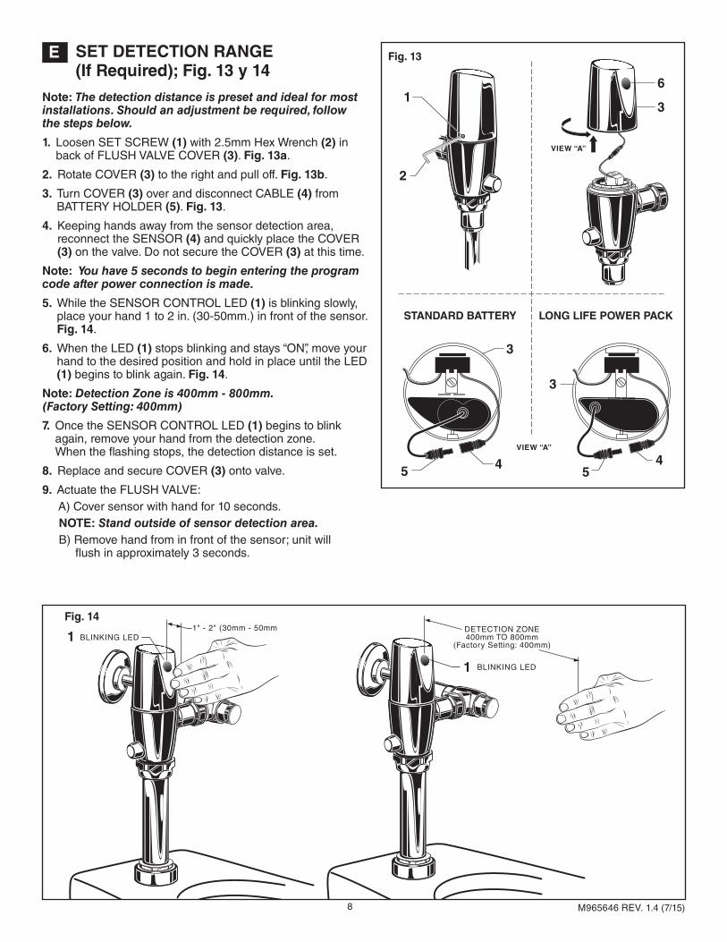
E SET DETECTION RANGE (If Required); Fig. 13 y 14
Note: The detection distance is preset and ideal for most installations. Should an adjustment be required, follow the steps below.
1. Loosen SET SCREW (1) with 2.5mm Hex Wrench (2) in back of FLUSH VALVE COVER (3). Fig. 13a.
2. Rotate COVER (3) to the right and pull off. Fig. 13b.
3. Turn COVER (3) over and disconnect CABLE (4) from BATTERY HOLDER (5). Fig. 13.
4. Keeping hands away from the sensor detection area, reconnect the SENSOR (4) and quickly place the COVER (3) on the valve. Do not secure the COVER (3) at this time.
Note: You have 5 seconds to begin entering the program code after power connection is made.
5. While the SENSOR CONTROL LED (1) is blinking slowly, place your hand 1 to 2 in. (30-50mm.) in front of the sensor. Fig. 14.
6. When the LED (1) stops blinking and stays “ON”, move your hand to the desired position and hold in place until the LED (1) begins to blink again. Fig. 14.
Note: Detection Zone is 400mm - 800mm.(Factory Setting: 400mm)
7. Once the SENSOR CONTROL LED (1) begins to blink again, remove your hand from the detection zone. When the flashing stops, the detection distance is set.
8. Replace and secure COVER (3) onto valve.
9. Actuate the FLUSH VALVE: A) Cover sensor with hand for 10 seconds. NOTE: Stand outside of sensor detection area. B) Remove hand from in front of the sensor; unit will flush in approximately 3 seconds.
1
1
1" - 2" (30mm - 50mmBLINKING LED
BLINKING LED
Fig. 14DETECTION ZONE400mm TO 800mm
(Factory Setting: 400mm)
9
TROUBLESHOOTING FLOW CHARTS
NNOO
YYEESS
NNOO
YYEESS
NNOO
11 22
11 22
YYEESS
NNOO
YYEESS
NNOO
UNIT DOES NOT FUNCTION
NNOO
NNOO
11
22
11
22
YYEESS
NNOO
NNOO
YYEESS
UNIT WILL ONLY FLUSH MANUALLY
YYEESS
NNOO
NNOO
11
22
11
22
NNOO
YYEESS
UNIT IS CONTINUOUSLY FLUSHING
OPEN VALVE
CRITICALLY LOW BATTERY . INSTALLNEW BATTERY
DEAD BATTERY. INSTALL NEWBATTERY. REPEAT.
DAMAGED SENSOR WIRE. REPLACESENSOR. (ONLY IF ABSOLUTELY NEEDED)
To learn more about American Standard Selectronic® Products visit our website at:www.americanstandard-us.com or e-mail us at: [email protected]
Mon. - Fri. 8:00 a.m. to 8:00 p.m. EST Saturday 10:00 a.m. to 4:00 p.m. EST
M965646 REV. 1.4 (7/15)
10
M950319-0071600ASENSOR ASSEMBLY (1.6 gpf)
M950319-0071280ASENSOR ASSEMBLY (1.28 gpf)
M950319-0071100ASENSOR ASSEMBLY (1.1 gpf)
M950319-0074000ASENSOR ASSEMBLY
(1.6/1.1 gpf)
M950319-0075000ASENSOR ASSEMBLY
(1.28/1.1 gpf)
M964411-0020A1" VACUUM BREAKER
M950354-0020AMANUAL VALVE
M964402-0070AVACUUM BREAKER KIT
A955056-0020A1" STOP VALVE KIT
M964945-0020AADJUSTABLE TAILPIECE(4-1/4" to 5-1/4" Rough-in)
OPTIONAL ADJUSTABLE TAILPIECE(Purchased Separately)M962836-0020A (8-1/4" to 9-1/4" Rough-in)M962835-0020A (7-1/4" to 8-1/4" Rough-in)M962834-0020A (6-1/4" to 7-1/4" Rough-in)M962833-0020A (5-1/4" to 6-1/4" Rough-in)
A955057-0020A1" INLET PIPE ASSEMBLY
M950514-0070ABATTERY HOLDER
A923654-0070ABATTERY 6V CR-P2 CR-P2
M950361-0070ALONG LIFE
POWER PACK
Standard Battery6065 Series
Long Life Power Pack6066 Series
Power Source
M906684-0070ABONNET NUT
A917376-0070ASET SCREW
M906684-0070ABONNET NUT
M964942-0021600ACOVER ASSEMBLY (1.6 gpf)
M964942-0021280ACOVER ASSEMBLY (1.28 gpf)
M964942-0024000ACOVER ASSEMBLY (1.6/1.1 gpf)
M964942-0023000ACOVER ASSEMBLY (1.28/1.1 gpf)
M964942-0021100ACOVER ASSEMBLY (1.1 gpf)
M964949-0021600ACOVER ASSEMBLY (1.6 gpf)
M964949-0021280ACOVER ASSEMBLY (1.28 gpf)
M964949-0024000ACOVER ASSEMBLY (1.6/1.1 gpf)
M964949-0023000ACOVER ASSEMBLY (1.28/1.1 gpf)
M964949-0021100ACOVER ASSEMBLY (1.1 gpf)
M964952-0070APISTON ASSEMBLY
M964948-0070ASOLENOID ASSEMBLY
M964953-0070ASOLENOID & PISTON
SUBASSEMBLY
M964551-0070APISTON ASSEMBLY
M964302-0070ASOLENOID ASSEMBLY
M964852-0070ASOLENOID & PISTON
SUB ASSEMBLY
Standard Battery (6065 Series) Long Life Power Pack (6066 Series)