Self-Centering Steel Frame Systems NEESR-SG: Self-Centering Damage-Free Seismic-Resistant Steel Frame Systems Project Team Richard Sause, James Ricles, David Roke, Choung-Yeol Seo, Michael Wolski, Geoff Madrazo ATLSS Center, Lehigh University Maria Garlock, Erik VanMarcke, Li-Shiuan Peh Princeton University Judy Liu Purdue University Keh-Chyuan Tsai NCREE, National Taiwan University
Transcript
Self-Centering Steel Frame Systems
NEESR-SG: Self-Centering Damage-Free Seismic-Resistant Steel Frame Systems
Project TeamRichard Sause, James Ricles, David Roke,
Choung-Yeol Seo, Michael Wolski, Geoff Madrazo ATLSS Center, Lehigh University
Maria Garlock, Erik VanMarcke, Li-Shiuan PehPrinceton University
This material is based on work supported by the National Science Foundation, Award No. CMS-0420974, in the George E. Brown, Jr. Network for Earthquake Engineering Simulation Research (NEESR) program, and Award No. CMS-0402490 NEES Consortium Operation.
Motivation: Expected Damage for Conventional Steel Frames
Conventional Moment Resisting Frame System
(b)
(a)
Reduced beam section (RBS) beam-column test specimen with slab: (a) at 3% drift, (b) at 4% drift.
Self Centering (SC) Seismic-Resistant System Concepts
Discrete structural members are post-tensioned to pre-compress joints.
Gap opening at joints at selected earthquake load levels provides softening of lateral force-drift behavior without damage to members.
PT forces close joints and permanent lateral drift is avoided.
Previous Work on SC Steel Moment Resisting (MRF) Connections
MRF Subassembly with PT Connections
-500
-400
-300
-200
-100
0
100
200
300
400
500
-150 -100 -50 0 50 100 150
Lateral Displacement - (mm)
Late
ral L
oad
- H
(K
N) FR
Stiffness with welded connection
Initial Stiffness Is Similar to Stiffness of Conventional Systems
H
PT Steel MRF
MRF subassembly with post-tensioned connections
Steel MRF subassembly with post-tensioned connections and angles at 3% drift
Lateral Force-Drift Behavior Softens Due to Gap Opening
Lateral Force-Drift Behavior Softens Without Significant Damage
• Conventional steel MRFs soften by inelastic deformation, which damages main structural members and results in residual drift
• SC steel MRF softens by gap opening and reduced contact area at joints
H
-600
-400
-200
0
200
400
600
-8 -6 -4 -2 0 2 4 6 8
Displacement, (in)
Lat
eral
Lo
ad, H
(ki
ps)
Post-Tensioned Connection
Welded Connection
Energy Dissipation from Energy Dissipation (ED) Elements
-400
-300
-200
-100
0
100
200
300
400
-150 -100 -50 0 50 100 150
Lateral Displacement, [mm]
Lat
eral
Lo
ad,
H [
KN
]
Specimen PC2L6x6x5/16, g/t = 4
Specimen PC4L8x8x5/8, g/t = 4
Steel MRF subassemblies with post-tensioned connections with different size ED elements.
H
Steel MRF
Limited, Repairable Damage
@ 4% DriftBefore testing After testing
Angle fracture
Summary of SC Seismic-Resistant Structural System Behavior
• Initial lateral stiffness is similar to that of conventional seismic-resistant systems.
• Lateral force-drift behavior softens due to gap opening at selected joints and without significant damage to main structural members.
• Lateral force-drift behavior softening due to gap opening controls force demands.
• Energy dissipation provided by energy dissipation (ED) elements, not from damage to main structural members.
NEESR-SG: Self-Centering Damage-Free Seismic-
Resistant Steel Frame Systems
• Project Scope.
• Project Goals.
• Status of Selected Research Tasks.
• Summary.
NEESR-SG: SC Steel Frame Systems Project Scope
• Develop two SC steel frame systems:– Moment-resisting frames (SC-MRFs).
– Concentrically-braced frames (SC-CBFs).
• Conduct large-scale experiments utilizing:– NEES ES (RTMD facility) at Lehigh.
– non-NEES laboratory (Purdue).
– international collaborating laboratory (NCREE)
• Conduct analytical and design studies of prototype buildings.
• Develop design criteria and design procedures.
NEESR-SG: SC Steel Frame Systems Project Goals
• Overall: self-centering steel systems that are constructible, economical, and structurally damage-free under design earthquake.
• Specific:– Fundamental knowledge of seismic behavior of SC-
MRF systems and SC-CBF systems.– Integrated design, analysis, and experimental
research using NEES facilities.– Performance-based, reliability-based seismic design
procedures.
NEESR-SG: Self-Centering Damage-Free Seismic-
Resistant Steel Frame Systems
• Project Scope.
• Project Goals.
• Status of Selected Research Tasks.
• Summary.
NEESR-SG: SC Steel Frame Systems Project Research Tasks
1. Develop reliability-based seismic design and assessment procedures.
2. Develop SC-CBF systems.3. Further develop SC-MRF systems.4. Develop energy dissipation elements for SC-MRFs and SC-CBFs.5. Develop sensor networks for damage monitoring and integrity
assessment.6. Design prototype buildings.7. Perform nonlinear analyses of prototype buildings.8. Conduct large-scale laboratory tests of SC-MRFs and SC-CBFs.9. Collaborate on 3-D large-scale laboratory tests on SC-MRF and SC-
CBF systems.
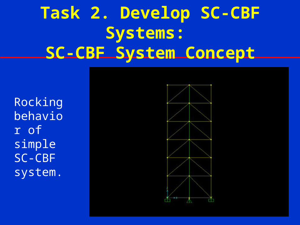
Task 2. Develop SC-CBF Systems: SC-CBF System Concept
Rocking behavior of simple SC-CBF system.
More Complex SC-CBF Configurations Being Considered
basebase
V
P01P01+P
g g
g
g
g
g
g
g
g
g
g
g
P02P02+P
V
col
roof
SC-CBF Design Criteria
Δgap
PT steel yields Member yields
Column
Decompression
PT Yielding
Significant
Yielding of
Frame
Members
Failure of
Frame
Members
DBE
MCE
Lateral Force
Roof Drift
IO CPLS
Current Work on SC-CBF Systems
• Evaluate frame configurations.
• Evaluate effect of energy dissipation (ED) elements.
• Develop and evaluate performance-based design approach.