24 Self-diagnosis The readiness code The readiness code is an 8-digit numeric code which indicates the status of the exhaust emission diagnoses. The diagnoses are performed at regular intervals during normal vehicle operation. The readiness code does not indicate whether there are any faults in the system. It indicates whether certain diagnosis have been terminated -0- or have not been performed yet, or have been cancelled -1-. If the engine management system has registered a fault and stored this fault in the fault memory, the fault message can only be obtained with a fault reader. The readiness code can be read out using the Vehicle Diagnostic, Testing and Information System VAS 5051 or the V.A.G Diagnostic Unit using function “15” which can be accessed via address word “01”. The readiness code can also be generated by performing a short test. Relevance of the 8-digit numeric block to the readiness code The readiness code is only generated when all the digit positions on the display are 0. 1 2 3 4 5 6 7 8 Diagnostic function 0 Catalytic converter 0 Catalytic converter heating (diagnosis function currently inactive/always “0”) 0 Activated charcoal canister system (fuel tank purging system) 0 Secondary air system 0 Air conditioning system (diagnosis function currently inactive/always “0”) 0 Lambda probe 0 Lambda probe heater (diagnosis function currently inactive/always “0”) 0 Exhaust gas recirculation (not existent/always “0”) Readiness code The readiness code for both engines is identical. 202_002
Transcript
24
Self-diagnosis
The readiness code
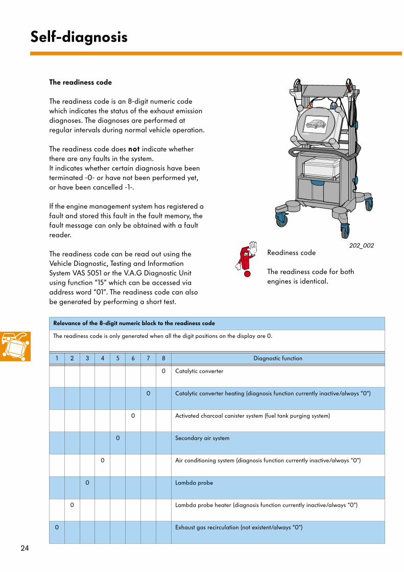
The readiness code is an 8-digit numeric code which indicates the status of the exhaust emission diagnoses. The diagnoses are performed at regular intervals during normal vehicle operation.
The readiness code does nnnnooootttt indicate whether there are any faults in the system.It indicates whether certain diagnosis have been terminated -0- or have not been performed yet, or have been cancelled -1-.
If the engine management system has registered a fault and stored this fault in the fault memory, the fault message can only be obtained with a fault reader.
The readiness code can be read out using the Vehicle Diagnostic, Testing and Information System VAS 5051 or the V.A.G Diagnostic Unit using function “15” which can be accessed via address word “01”. The readiness code can also be generated by performing a short test.
Relevance of the 8-digit numeric block to the readiness code
The readiness code is only generated when all the digit positions on the display are 0.
1 2 3 4 5 6 7 8 Diagnostic function
0 Catalytic converter
0 Catalytic converter heating (diagnosis function currently inactive/always “0”)
0 Activated charcoal canister system (fuel tank purging system)
0 Secondary air system
0 Air conditioning system (diagnosis function currently inactive/always “0”)
0 Lambda probe
0 Lambda probe heater (diagnosis function currently inactive/always “0”)
0 Exhaust gas recirculation (not existent/always “0”)
Readiness code
The readiness code for both engines is identical.
202_002
25
CA
N-B
us
H
CA
N-B
us
L
The Motronic 5.9.2 control unit has a fault memory.
The self-diagnosis function monitors all the colour-coded parts of the system.
The self-diagnosis procedure can be performed using the Vehicle Diagnostic, Testing and Information System VAS 5051 or the V.A.G Diagnostic Unit.
The self-diagnosis procedure is initiated with the address word01 - Engine electronics.
The following functions are possible:
01 - Interrogate control unit version02 - Interrogate fault memory03 - Actuator diagnosis04 - Basic adjustment05 - Erase fault memory06 - End of output07 - Encode control unit08 - Read data block10 - Adaption11 - Login procedure15 - Read out readiness code
233_018
Function 04 - Basic adjustment must be executed after changing the engine control unit, the throttle valve control part or the engine and after disconnecting the battery.Advise your customers to visit a workshop to have basic adjustment performed after replacing the battery themselves or after disconnecting and connecting the battery.
202_002
For the various individual fault codes, please refer to the Workshop Manual for Motronic Injection and Ignition System (2.0-litre engine).
26
2.0-litre/88 kW engine ATF/ASU
The 2.0-litre/88 kW Flino engine is described below. Flino stands for "flying camshaft“. The engine will be used in A-platform vehicles, in which it will be mounted transversely, and in the Passat, in which it will be mounted longitudinally.
The improved version of the 2.0-litre engine includes the following characteristic modifications:
– Adjustment of the intake cam– The system components for service interval
extension (new engine oil, engine oil level sensor and engine oil temperature sensor)
– Twin-path intake manifold– Electric throttle drive
The engine-specific requirements relating to service interval extension and camshaft timing control are described.
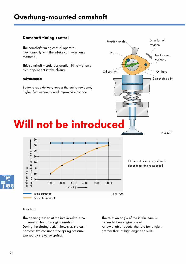
Better torque delivery across the entire rev band, higher fuel economy and improved elasticity.
Function
The opening action at the intake valve is no different to that on a rigid camshaft.During the closing action, however, the cam becomes twisted under the spring pressure exerted by the valve spring.
The rotation angle of the intake cam is dependent on engine speed.At low engine speeds, the rotation angle is greater than at high engine speeds.
233_042
Camshaft body
Intake cam,variable
Direction of rotation
Roller
Rotation angle
Oil cushion Oil bore
1000 2000 3000 4000 5000 6000-20
-10
0
10
20
30
40
50
Rigid camshaft
Variable camshaft
Inta
ke p
ort c
lose
s
(deg
rees
cra
nksh
aft a
fter
DBC
)
233_043
Intake port - closing - position in
dependence on engine speed
Overhung-mounted camshaft
Will not be introduced
29
Function 85 kW engine 88 kW engine
Camshaft The shaft, intake cam and exhaust cam are a single part
A camshaft body with one oil bore aligned longitudinally and transversely in relation to the intake cam. Exhaust cam with fitting key securely connected to the body. Intake cam mounted rotatably on body. An inserted roller drives the cam and limits the angle of rotation.Oil pressure is applied to the empty space in the cam above the camshaft body. The oil cushion dampens the rotary motion and absorbs noise.
Adjustment none The intake cam is turned depending on engine speed. It rotates under the force exerted by the valve spring in the direction of rotation of the camshaft, but more quickly than the camshaft itself rotates.The cam "flies" ahead of the camshaft.
Timing The exhaust port and intake valve have fixed timings
The exhaust valve has a fixed timingThe intake valve has a fixed timing for the start of the opening movement and a variable timing for the end of the opening movement.
233_044
Fitting key
Bush
Intake cam
Bush
Spring
Exhaust cam
Bush
Roller
Fitting key
Camshaft body
Exhaust cam
Intake cam
Please refer to SSP 229 for more detailed information.
Will not be introduced
30
System overview - ATF/ASU
CA
N-B
us
+
CA
N-B
us
-
Engine speed sender G28
Hall sender G40
Hot filmair mass meter G70 andintake air temperature sender G42
Lambda probe after catalytic converter G130
Coolant temperature sender G62
Knock sensor I G61
Auxiliary signals:Air conditioner compressor ONA/C readyRoad speed signal
Knock sensor II G66
Accelerator position senders G79 and G185
Lambda probe G39
Clutch pedal switch F36
Brake light switch F andbrake light switch F47
Throttle valve control unit J338 (EPC positioner)Angle senders for throttle valvedrive G187 and G188
Will not be introduced
31
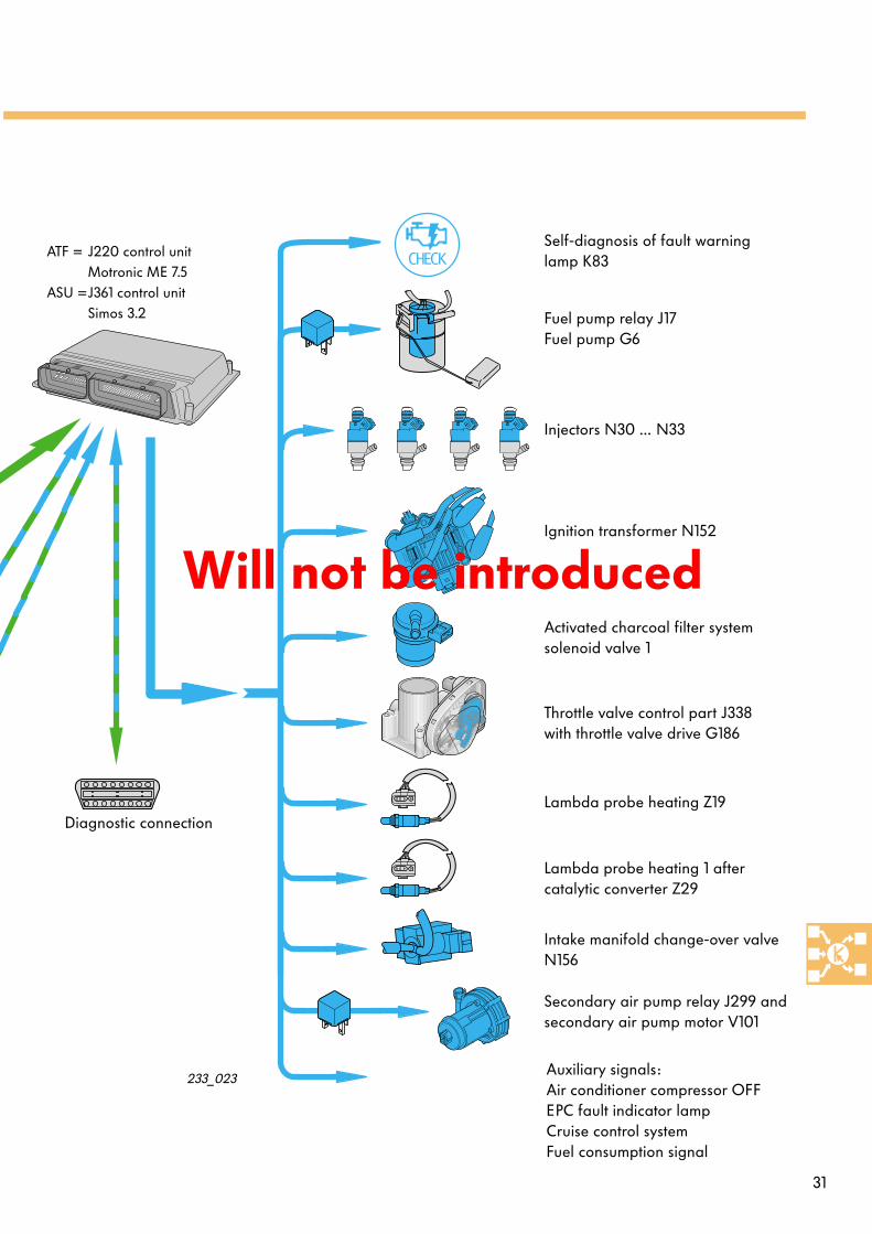
ATF = J220 control unit Motronic ME 7.5
ASU =J361 control unit Simos 3.2
Diagnostic connection
Fuel pump relay J17Fuel pump G6
Injectors N30 … N33
Ignition transformer N152
Activated charcoal filter systemsolenoid valve 1
Throttle valve control part J338with throttle valve drive G186
Lambda probe heating Z19
Secondary air pump relay J299 and secondary air pump motor V101
(upstream of catalytic converter)Z28 Heater for lambda probe 2Z29 Heater for lambda probe 1
(downstream of catalytic converter)
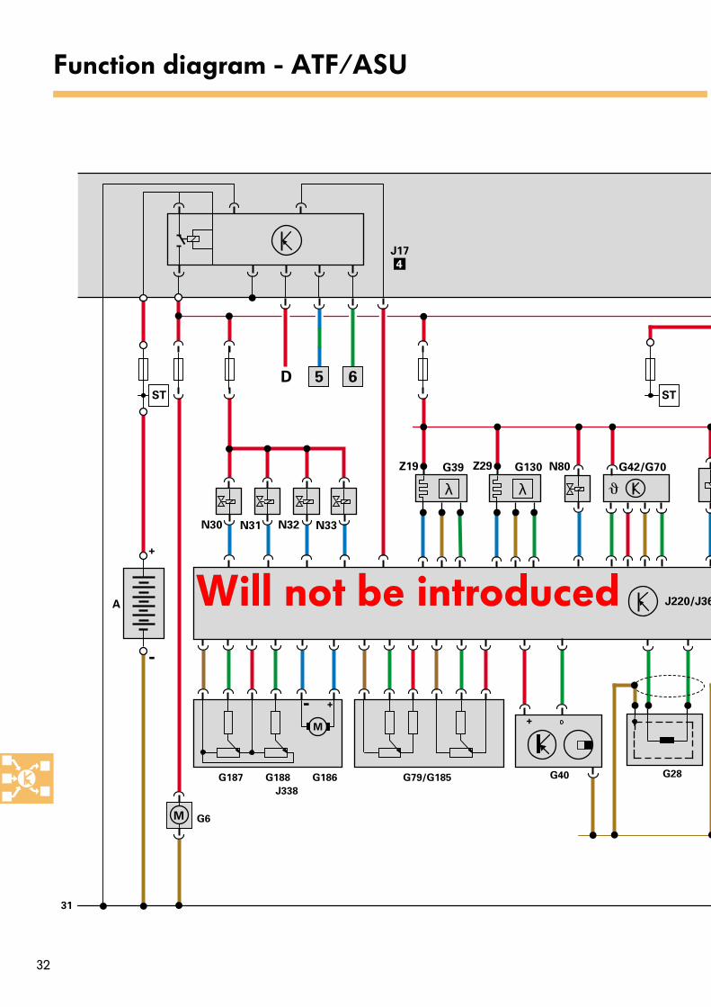
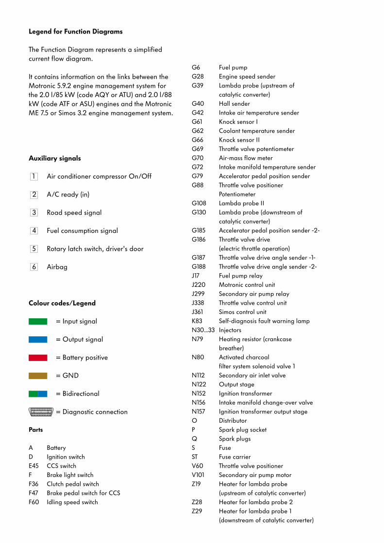
Legend for Function Diagrams
The Function Diagram represents a simplified current flow diagram.
It contains information on the links between the Motronic 5.9.2 engine management system for the 2.0 l/85 kW (code AQY or ATU) and 2.0 l/88 kW (code ATF or ASU) engines and the Motronic ME 7.5 or Simos 3.2 engine management system.
Auxiliary signals
1 Air conditioner compressor On/Off
2 A/C ready (in)
3 Road speed signal
4 Fuel consumption signal
5 Rotary latch switch, driver's door
6 Airbag
Colour codes/Legend
= Input signal
= Output signal
= Battery positive
= GND
= Bidirectional
= Diagnostic connection
Parts
A BatteryD Ignition switchE45 CCS switchF Brake light switchF36 Clutch pedal switchF47 Brake pedal switch for CCSF60 Idling speed switch
34
System components for service inter-val extension
The 88 kW engine has technical features which extend the vehicle's maintenance intervals. This has both economical and ecological benefits.In addition to the new engine production technology (reduced bearing clearance, precision honing), these features include a new type of oil and an engine oil sensor.
Customers can fully utilise the period up to the next service in accordance with their individual driving style and conditions of use.The oil level and service requirements are indicated to the customer visually.
53
2
1
6
7
41/min x 1000
10080
60
120
km/h
40
20
160
180
200
220
240
140
Oil grade VW 50300
Engine oil sensor
Brake pad wear
indicator
Battery - maintenance-
free (lead-calcium)
Flexible service interval displayOil level
calculated from
Mileage (km) readingOil temperature
Fuel consumption
233_045
New
elements
New
service
New
evaluation
and
information
Maintenance interval extension
Service interval extension
35
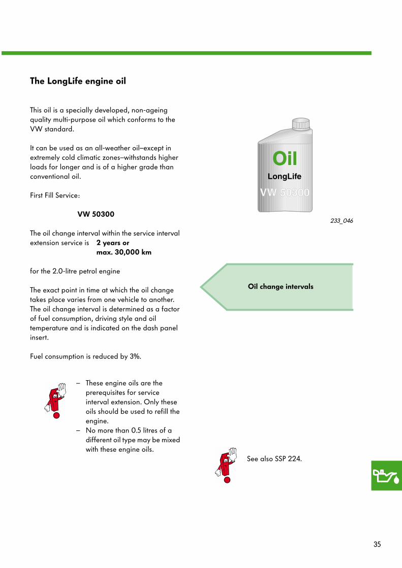
The LongLife engine oil
This oil is a specially developed, non-ageing quality multi-purpose oil which conforms to the VW standard.
It can be used as an all-weather oil–except in extremely cold climatic zones–withstands higher loads for longer and is of a higher grade than conventional oil.
First Fill Service:
VW 50300
The oil change interval within the service interval extension service is 2 years or
max. 30,000 km
for the 2.0-litre petrol engine
The exact point in time at which the oil change takes place varies from one vehicle to another. The oil change interval is determined as a factor of fuel consumption, driving style and oil temperature and is indicated on the dash panel insert.
Fuel consumption is reduced by 3%.
Oil change intervals
233_046
– These engine oils are the prerequisites for service interval extension. Only these oils should be used to refill the engine.
– No more than 0.5 litres of a different oil type may be mixed with these engine oils.
See also SSP 224.
36
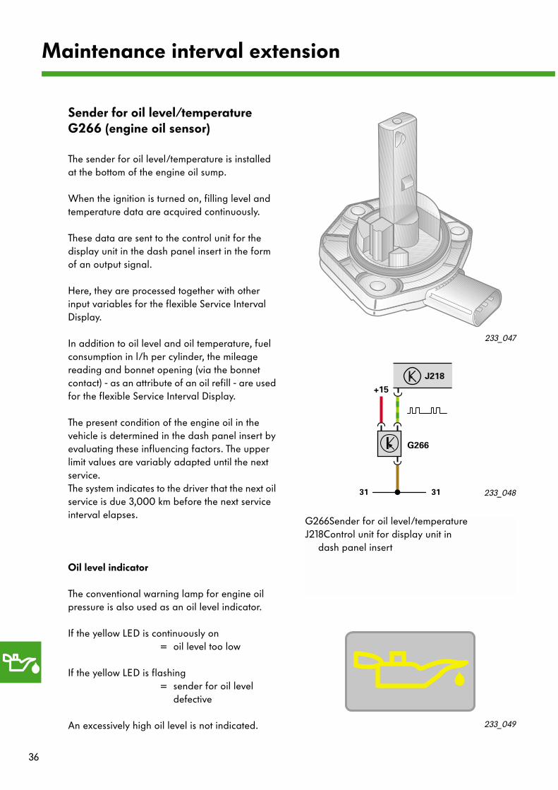
Sender for oil level/temperature G266 (engine oil sensor)
The sender for oil level/temperature is installed at the bottom of the engine oil sump.
When the ignition is turned on, filling level and temperature data are acquired continuously.
These data are sent to the control unit for the display unit in the dash panel insert in the form of an output signal.
Here, they are processed together with other input variables for the flexible Service Interval Display.
In addition to oil level and oil temperature, fuel consumption in l/h per cylinder, the mileage reading and bonnet opening (via the bonnet contact) - as an attribute of an oil refill - are used for the flexible Service Interval Display.
The present condition of the engine oil in the vehicle is determined in the dash panel insert by evaluating these influencing factors. The upper limit values are variably adapted until the next service.The system indicates to the driver that the next oil service is due 3,000 km before the next service interval elapses.
Oil level indicator
The conventional warning lamp for engine oil pressure is also used as an oil level indicator.
If the yellow LED is continuously on= oil level too low
If the yellow LED is flashing= sender for oil level
defective
An excessively high oil level is not indicated.
233_048
233_049
G266Sender for oil level/temperatureJ218Control unit for display unit in
dash panel insert
31
J218
+15
G266
31
233_047
Maintenance interval extension
37
Oil level
The oil level can be calculated in mm from the cool-down time during the cool-down phase by means of a sensor equation. The calculation is accurate to approx. ± 2 mm.
The more oil there is in the oil sump, the quicker the sensor will cool down again.
Long cool-down time = low oil level
Short cool-down time = normal
Oil temperature
During the cool-down phase of the sensor, the oil temperature signal is also transmitted.
Signal waveform and evaluation
The measuring element is briefly heated via the present oil temperature (output = High) and then cools down again (output = Low).
This procedure is repeated continuously. The High times are dependent on the oil temperature and the Low times are proportional to the filling level.
High
Low
Cool-down phase 200 - 1,000 ms
Heating phase
Oil temperature evaluation25 - 85 ms
+
-
53
2
1
6
7
41/min x 1000
10080
60
120
km/h
40
20
160
180
200
220
240
140
G266
233_050
Filling level sensor
Temperature sensor
Temperature
Filling level
233_026
38
Test your knowledge
1. The position of the camshaft in the AQY engine is indicated by Hall sender G40.It has
A. a measurement window with the same width for each cylinder,B. four different measurement windows,C. two narrow measurement windows and two wide measurement windows
which generate a characteristic signal for each 90o crankshaft rotation .
2. The injectors of the AQY engine are
A. identical to those used in the 1.6-litre and 1.8-litre engines.B. also fitted with an air shroud.C. of the so-called “top feed” type.
3. The crankcase has a breather to compensate for pressure differences.The mixture of gas and oil vapour is ………………………… recirculated.To prevent the mixture condensing on entry, the inlet is heated. This process takes place
A. throughout winter operation.B. continuously when the ignition is "on".C. during the starting cycle (much like a diesel glow plug).
4. By injecting additional air (secondary air) into the exhaust gas,the pollutants in the exhaust gasare recombusted.As a result,
A. the catalytic converter reaches its operating temperature quickly.B. the pollutant components CO and HC are reduced.C. the engine runs with an air surplus.
5. The secondary air system is
A. continuously active.B. only active during the cold start phase.C. active during the cold start phase and in the idling phase after a warm start.D. featured in both engines.
Which of these answers is/are correct?Sometimes only one answer is correct.However, more than one or all of the answers may be correct.Please fill in the gaps.
39
6. The combination valve in the secondary air system on the ATU engine
A. is activated electro-pneumatically by the engine control unit.B. is a vacuum controlled pneumatic valve.C. is a pneumatic valve which is activated by a separate electro-pneumatic valve.
7. The advantages of the twin-probe lambda control are:
A. Quick and precise lambda control.B. The conversion efficiency of the catalytic converter is checked.C. Malfunctioning of the catalytic converter
is detected by comparing the probe voltages with a setpoint.
8. The readiness code
A. indicates that diagnoses are in progress to ensure vehicle operation in conformity with the prescribed emission limits.
B. indicates faults in the exhaust emission control system.C. can be generated and read out.
9. The new Motronic 5.9.2 is a generation of engine control units featuring
A. technical improvements for starting the engine,low fuel consumption and reduced exhaust emission.
B. technical control systems for intake air temperature stabilisation.C. meeting the requirements for OBD II.
10 . The ATU and AQY engines have different
A. distributors.B. engine mounts.C. numbers of knock sensors.
Solutions
1. C.; 2. B., C.; 3. in the intake manifold, B.; 4. A., B.; 5. C., D.; 6. C.; 7. A., B., C.; 8. A., C.; 9. A., C.10. A., B., C.