TRINITRON® COLOR TV KV-27S40 RM-Y165 US SCC-S01H-A KV-27S40 RM-Y165 CND SCC-S03E-A KV-27S45 RM-Y167 US SCC-S01J-A KV-27S45 RM-Y167 CND SCC-S03F-A KV-27S65 RM-Y167 US SCC-S01K-A KV-27S65 RM-Y167 CND SCC-S03G-A KV-29SL40 RM-Y165 E SCC-S04X-A KV-29SL40A RM-Y165 E SCC-S04S-A KV-29SL40C RM-Y165 E SCC-S04U-A KV-29SL45 RM-Y167 E SCC-S04Y-A KV-29SL65 RM-Y167 E SCC-S06F-A KV-29SL65C RM-Y167 E SCC-S04V-A KV-29XL40M RM-Y165 MX SCC-S02D-A KV-29XL40P RM-Y165 E SCC-S04R-A KV-29XT11A RM-Y165 E SCC-S04T-A MODEL COMMANDER DEST . CHASSIS NO . KV-27S45 SERVICE MANUAL CHASSIS BA-4 SELF-DIAGNOSTIC FUNCTION RM-Y167
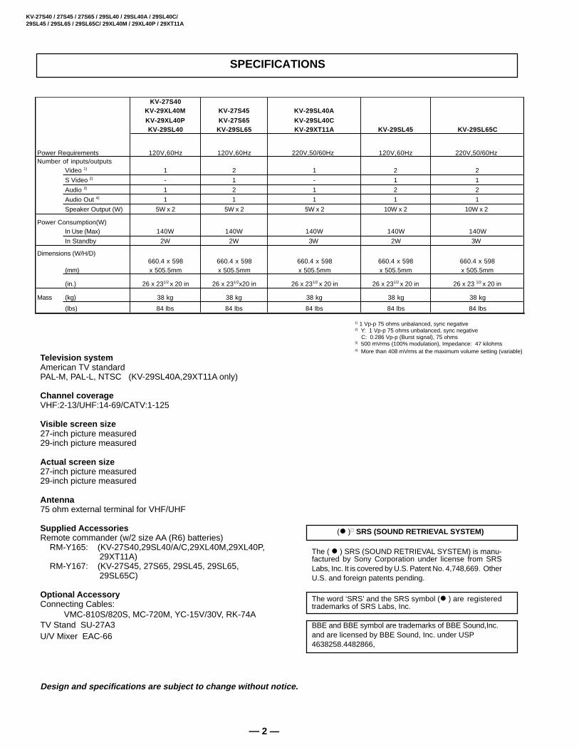
1) 1 Vp-p 75 ohms unbalanced, sync negative2) Y: 1 Vp-p 75 ohms unbalanced, sync negative C: 0.286 Vp-p (Burst signal), 75 ohms3) 500 mVrms (100% modulation), Impedance: 47 kilohms4) More than 408 mVrms at the maximum volume setting (variable)
Design and specifications are subject to change without notice.
(l ) SRS (SOUND RETRIEVAL SYSTEM)
The ( l ) SRS (SOUND RETRIEVAL SYSTEM) is manu-factured by Sony Corporation under license from SRSLabs, Inc. It is covered by U.S. Patent No. 4,748,669. OtherU.S. and foreign patents pending.
The word ‘SRS’ and the SRS symbol (l ) are registeredtrademarks of SRS Labs, Inc.
BBE and BBE symbol are trademarks of BBE Sound,Inc.and are licensed by BBE Sound, Inc. under USP4638258.4482866,
SHORT CIRCUIT THE ANODE OF THE PICTURE TUBE ANDTHE ANODE CAP TO THE METAL CHASSIS, CRT SHIELD,OR CARBON PAINTED ON THE CRT, AFTER REMOVINGTHE ANODE.
WARNING!!
AN ISOLATION TRANSFORMER SHOULD BE USEDDURING ANY SERVICE TO AVOID POSSIBLE SHOCKHAZARD, BECAUSE OF LIVE CHASSIS.THE CHASSIS OFTHIS RECEIVER IS DIRECTLY CONNECTED TO THE ACPOWER LINE.
SAFETY-RELATED COMPONENT WARNING!!
COMPONENTS IDENTIFIED BY SHADING AND MARK¡ ON THE SCHEMATIC DIAGRAMS, EXPLODED VIEWSAND IN THE PARTS LIST ARE CRITICAL FOR SAFEOPERATION. REPLACE THESE COMPONENTS WITHSONY PARTS WHOSE PART NUMBERS APPEAR ASSHOWN IN THIS MANUAL OR IN SUPPLEMENTSPUBLISHED BY SONY. CIRCUIT ADJUSTMENTS THATARE CRITICAL FOR SAFE OPERATION ARE IDENTIFIEDIN THIS MANUAL. FOLLOW THESE PROCEDURESWHENEVER CRITICAL COMPONENTS ARE REPLACEDOR IMPROPER OPERATION IS SUSPECTED.
ATTENTION
APRES AVOIR DECONNECTE LE CAP DE L'ANODE, COURT-CIRCUITERL'ANODE DU TUBE CATHODIQUE ET CELUI DE L'ANODE DU CAP AUCHASSIS METALLIQUE DE L'APPAREIL, OU AU COUCHE DE CARBONEPEINTE SUR LE TUBE CATHODIQUE OU AU BLINDAGE DU TUBECATHODIQUE.
ATTENTION!!
AFIN D'EVITER TOUT RESQUE D'ELECTROCUTION PROVENANT D'UNCHÁSSIS SOUS TENSION, UN TRANSFORMATEUR D'ISOLEMENT DOITETRE UTILISÉ LORS DE TOUT DÉPANNAGE. LE CHÁSSIS DE CERÉCEPTEUR EST DIRECTEMENT RACCORDÉ À L'ALIMENTATIONSECTEUR.
ATTENTION AUX COMPOSANTS RELATIFS A LA SECURITE!!
LES COMPOSANTS IDENTIFIES PAR UNE TRAME ET PAR UNE MARQUE¡ SUR LES SCHEMAS DE PRINCIPE, LES VUES EXPLOSEES ET LESLISTES DE PIECES SONT D'UNEIMPORTANCE CRITIQUE POUR LASECURITE DU FONCTIONNEMENT. NE LES REMPLACER QUE PAR DESCOMPOSANTS SONY DONT LE NUMERO DE PIECE EST INDIQUE DANSLE PRESENT MANUEL OU DANS DES SUPPLEMENTS PUBLIES PARSONY. LES REGLAGES DE CIRCUIT DONT L'IMPORTANCE EST CRITIQUEPOUR LA SECURITE DU FONCTIONNEMENT SONT IDENTIFIES DANSLE PRESENT MANUEL. SUIVRE CES PROCEDURES LORS DE CHAQUEREMPLACEMENT DE COMPOSANTS CRITIQUES, OU LORSQU'UNMAUVAIS FONTIONNEMENT SUSPECTE.
WARNINGS AND CAUTIONS
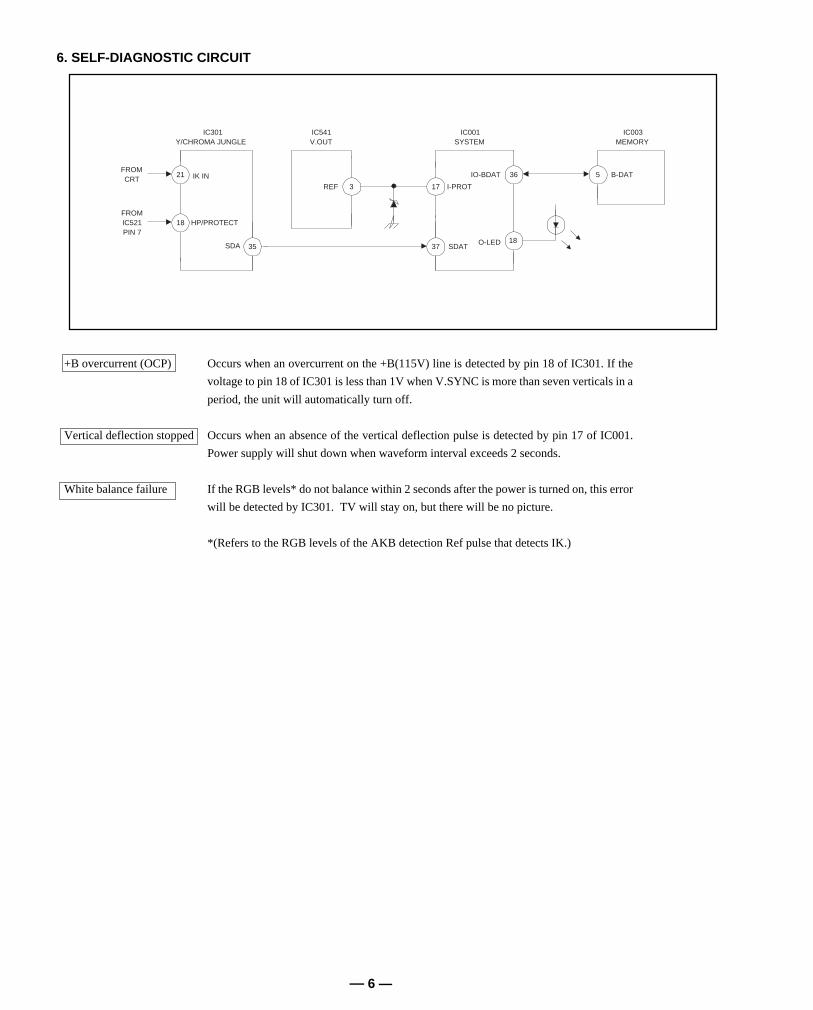
SELF-DIAGNOSTIC FUNCTION
The units in this manual contain a self-diagnostic function. If an error occurs, the STANDBY/TIMER lamp will automatically begin toflash. The number of times the lamp flashes translates to a probable source of the problem. A definition of the STANDBY/TIMER lampflash indicators is listed in the instruction manual for the user's knowledge and reference. If an error symptom cannot be reproduced, theremote commander can be used to review the failure occurrence data stored in memory to reveal past problems and how often theseproblems occur.
1. DIAGNOSTIC TEST INDICATORS
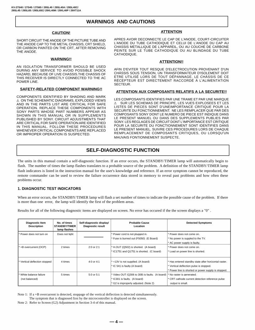
When an error occurs, the STANDBY/TIMER lamp will flash a set number of times to indicate the possible cause of the problem. If thereis more than one error, the lamp will identify the first of the problem areas.
Results for all of the following diagnostic items are displayed on screen. No error has occured if the the screen displays a "0" .
Note 1: If a +B overcurrent is detected, stoppage of the vertical deflection is detected simultaneously. The symptom that is diagnosed first by the microcontroller is displayed on the screen.
Note 2: Refer to Screen (G2) Adjustment in Section 3-4 of this manual.
Diagnostic Item No. of times Self-dia gnostic dis play/ Probable Cause Detected S ymptomsDescription STANDBY/TIMER Dia gnostic result Location
lamp flashes
* Power does not turn on Does not light * Power cord is not plugged in. * Power does not come on.
* Fuse is burned out (F5050) (E Board) * No power is suppled to the TV.
* AC power supply is faulty.
* +B overcurrent (OCP) 2 times 2:0 or 2:1 * H.OUT (Q502) is shorted. (A board) * Power does not come on.
* IC1751 and Q1751 is shorted. (C board) * Load on power line is shorted.
* Vertical deflection stopped 4 times 4:0 or 4:1 * +13V is not supplied. (A board) * Has entered standby state after horizontal raster.
* IC 541 is faulty (A board) * Vertical deflection pulse is stopped.
* Power line is shorted or power supply is stopped.
* White balance failure 5 times 5:0 or 5:1 * Video OUT (Q306 to 308) is faulty. (A board) * No raster is generated.
(not balanced) * IC301 is faulty. (A board) * CRT cathode current detection reference pulse
* G2 is improperly adjusted. (Note 2) output is small.
* One flash count is not used for self-diagnostic.
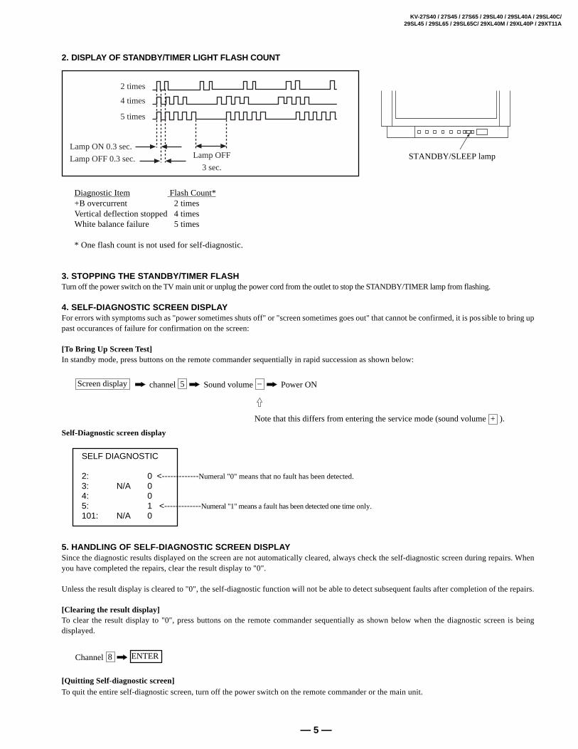
3. STOPPING THE STANDBY/TIMER FLASHTurn off the power switch on the TV main unit or unplug the power cord from the outlet to stop the STANDBY/TIMER lamp from flashing.
4. SELF-DIAGNOSTIC SCREEN DISPLAYFor errors with symptoms such as "power sometimes shuts off" or "screen sometimes goes out" that cannot be confirmed, it is possible to bring uppast occurances of failure for confirmation on the screen:
[To Bring Up Screen Test]In standby mode, press buttons on the remote commander sequentially in rapid succession as shown below:
Screen display channel 5 Sound volume – Power ON
Note that this differs from entering the service mode (sound volume + ).
Self-Diagnostic screen display
5. HANDLING OF SELF-DIAGNOSTIC SCREEN DISPLAYSince the diagnostic results displayed on the screen are not automatically cleared, always check the self-diagnostic screen during repairs. Whenyou have completed the repairs, clear the result display to "0".
Unless the result display is cleared to "0", the self-diagnostic function will not be able to detect subsequent faults after completion of the repairs.
[Clearing the result display]To clear the result display to "0", press buttons on the remote commander sequentially as shown below when the diagnostic screen is beingdisplayed.
Channel 8 ENTER
[Quitting Self-diagnostic screen]To quit the entire self-diagnostic screen, turn off the power switch on the remote commander or the main unit.
SELF DIAGNOSTIC
2: 0 <-------------Numeral "0" means that no fault has been detected.3: N/A 04: 05: 1 <-------------Numeral "1" means a fault has been detected one time only.101: N/A 0
After correcting the original service problem, perform thefollowing safety checks before releasing the set to thecustomer:
LEAKAGE TEST The AC leakage from any exposed metal part to earth groundand from all exposed metal parts to any exposed metal part havinga return to chassis, must not exceed 0.5 mA (500 microampere).Leakage current can be measured by any one of three methods.
1. A commercial leakage tester, such as the Simpson 229 orRCA WT-540A. Follow the manufacturers' instructions touse these instructions.
2. A battery-operated AC milliammeter. The Data Precision245 digital multimeter is suitable for this job.
3. Measuring the voltage drop across a resistor by means ofa VOM or battery-operated AC voltmeter. The "limit"indication is 0.75 V, so analog meters must have an accuratelow voltage scale. The Simpson's 250 and SanwaSH-63Trd are examples of passive VOMs that are suitable.Nearly all battery operated digital multimeters that have a2V AC range are suitable. (See Fig. A)
1. Check the area of your repair for unsoldered or poorly-soldered connections. Check the entire board surfacefor solder splashes and bridges.
2. Check the interboard wiring to ensure that no wiresare “pinched” or contact high-wattage resistors.
3. Check that all control knobs, shields, covers, groundstraps, and mounting hardware have been replaced.Be absolutely certain that you have replaced all theinsulators.
4. Look for unauthorized replacement parts, particularlytransistors, that were installed during a previousrepair. Point them out to the customer andrecommend their replacement.
5. Look for parts which, though functioning, showobvious signs of deterioration. Point them out tothe customer and recommend their replacement.
6. Check the line cords for cracks and abrasion.Recommend the replacement of any such line cordto the customer.
7. Check the B+ and HV to see if they are specifiedvalues. Make sure your instruments are accurate;be suspicious of your HV meter if sets always havelow HV.
8. Check the antenna terminals, metal trim, “metallized"knobs, screws, and all other exposed metal parts forAC Leakage. Check leakage as described below.
HOW TO FIND A GOOD EARTH GROUND A cold-water pipe is guaranteed earth ground; the cover-plateretaining screw on most AC outlet boxes is also at earth ground.If the retaining screw is to be used as your earth-ground, verifythat it is at ground by measuring the resistance between it and acold-water pipe with an ohmmeter. The reading should be zeroohms. If a cold-water pipe is not accessible, connect a 60-l00 wattstrouble light (not a neon lamp) between the hot side of the re-ceptacle and the retaining screw. Try both slots, if necessary, tolocate the hot side of the line, the lamp should light at normalbrilliance if the screw is at ground potential. (See Fig. B)
1.5 kΩ0.15 µFACVoltmeter(0.75 V)
To Exposed MetalParts on Set
Earth Ground
Fig. A. Using an AC voltmeter to check AC leakage.
Refer to the table below, it will direct you to the diagram suitable to the components you will beconnecting.
Cable or antenna only 5
Cable and antenna (KV-27S65, 27V65 only) 5
Cable box 6
Cable box and cable to view scrambled channels (KV-27S65, 27V65 only) 6
VCR and cable or antenna 7
VCR and cable box 7
Direct Broadcast Satellite Receiver (DBS) 8
VCR and Direct Broadcast Satellite Receiver (DBS) 9
Digital Versatile Disc receiver (DVD) 10
Audio system 10
Two VCRs for tape editing (KV-27V40, 27V45, 27V65 only) 11
Camcorder to view tapes 11
If you will be connecting See page
SECTION 1GENERAL
5
B• VHF only
or• UHF only
or• VHF/UHF
C• VHF
and
• UHF
Cable or Antenna Connections
A• VHF only
or• VHF/UHF
or• Cable
Antenna connector
(Rear of TV)VHF/UHF
300-ohm twinlead cable
(Rear of TV)VHF/UHF
75-ohmcoaxial cable
75-ohm coaxial cable
300-ohm twin lead cable
(Rear of TV)VHF/UHF
EAC-66 U/V mixer(not supplied)
(No connection "TOCONVERTER" in this case)
CATV cable
Antenna cable
Connecting directly to cable or anantenna
Cable and antenna
Note• In order to receive channels with an
antenna, you will need to turn your CABLEto OFF (see page 23) and perform theAUTO PROGRAM function.
The connection you choose will depend on thecable found in your home. Newer homes willbe equipped with standard coaxial cable(see A); older homes will probably have300 -ohm twin lead cable (see B); still otherhomes may contain both (see C ).
• KV-27S65, 27V65 only
If your cable provider does not feature localchannels, you may find this set up convenient.
Select Cable or ANT mode by pressing ANTon the remote control. You will be able toalternate between the two input sources.
TO CONVERTER
VHF/UHF
(Rear of TV)AUX
The instructions mentioned here are partial abstracts from the Operating Instruction Manual.The page numbers shown reflect those of the Operating Instruction Manual.
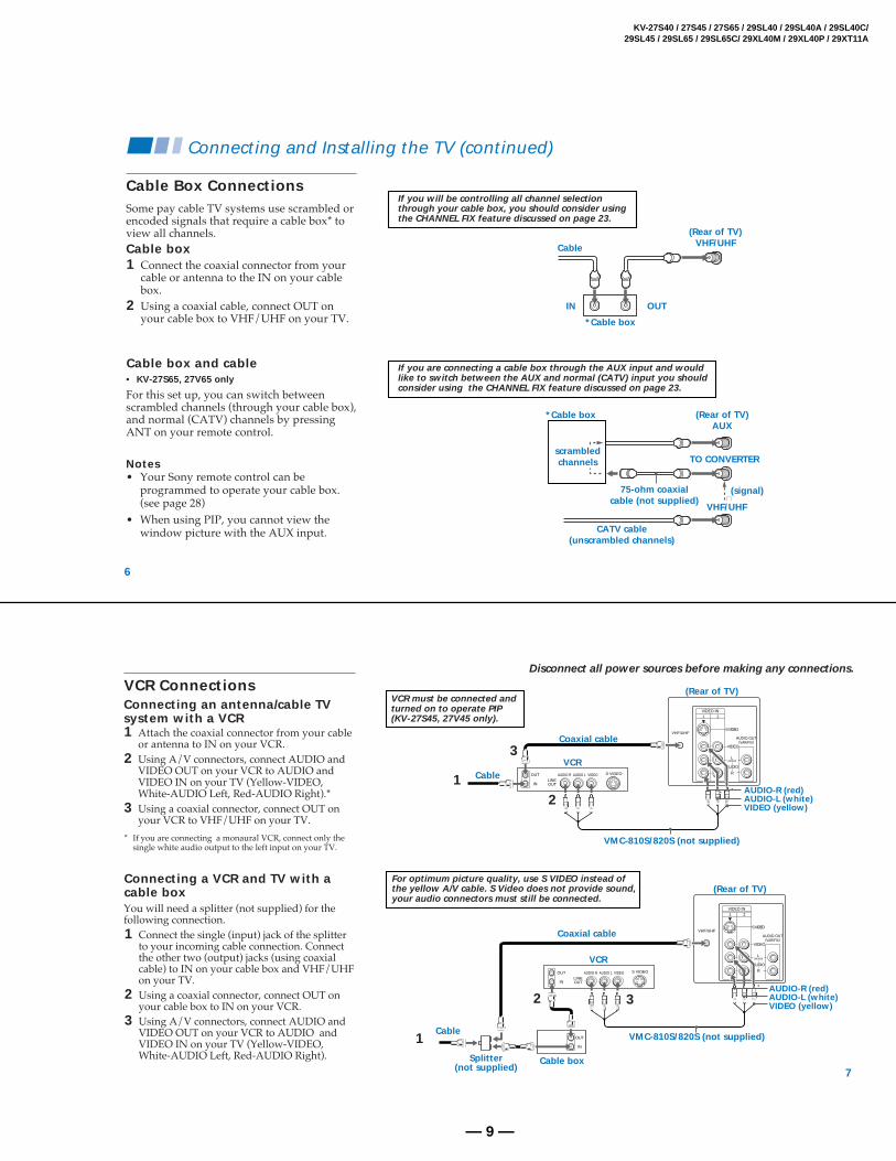
Some pay cable TV systems use scrambled orencoded signals that require a cable box* toview all channels.
scrambledchannels
If you will be controlling all channel selectionthrough your cable box, you should consider usingthe CHANNEL FIX feature discussed on page 23.
If you are connecting a cable box through the AUX input and wouldlike to switch between the AUX and normal (CATV) input you shouldconsider using the CHANNEL FIX feature discussed on page 23.
Cable box1 Connect the coaxial connector from your
cable or antenna to the IN on your cablebox.
2 Using a coaxial cable, connect OUT onyour cable box to VHF/UHF on your TV.
Cable box and cable• KV-27S65, 27V65 only
For this set up, you can switch betweenscrambled channels (through your cable box),and normal (CATV) channels by pressingANT on your remote control.
Notes• Your Sony remote control can be
programmed to operate your cable box.(see page 28)
• When using PIP, you cannot view thewindow picture with the AUX input.
7
Disconnect all power sources before making any connections.
VCR must be connected andturned on to operate PIP(KV-27S45, 27V45 only).
VCR Connections
AUDIO OUT(VAR/FIX)
VIDEO IN 1 2
VHF/UHFS VIDEO
VIDEO
L
R
AUDIO
(MONO)
AUDIO R AUDIO L VIDEO S VIDEO
LINEOUT
OUT
IN
Coaxial cable
(Rear of TV)
VMC-810S/820S (not supplied)
CableVCR
3
12
AUDIO-R (red)AUDIO-L (white)VIDEO (yellow)
AUDIO OUT(VAR/FIX)
VIDEO IN 1 2
VHF/UHFS VIDEO
VIDEO
L
R
AUDIO
(MONO)
AUDIO R AUDIO L VIDEO S VIDEO
LINEOUT
OUT
IN
OUT
IN
VMC-810S/820S (not supplied)
Cable boxSplitter(not supplied)
3AUDIO-R (red)AUDIO-L (white)VIDEO (yellow)
VCR
Cable
Coaxial cable
2
1
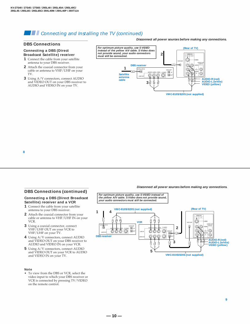
For optimum picture quality, use S VIDEO instead ofthe yellow A/V cable. S Video does not provide sound,your audio connectors must still be connected.
Connecting an antenna/cable TVsystem with a VCR
(Rear of TV)
You will need a splitter (not supplied) for thefollowing connection.1 Connect the single (input) jack of the splitter
to your incoming cable connection. Connectthe other two (output) jacks (using coaxialcable) to IN on your cable box and VHF/UHFon your TV.
2 Using a coaxial connector, connect OUT onyour cable box to IN on your VCR.
3 Using A/V connectors, connect AUDIO andVIDEO OUT on your VCR to AUDIO andVIDEO IN on your TV (Yellow-VIDEO,White-AUDIO Left, Red-AUDIO Right).
1 Attach the coaxial connector from your cableor antenna to IN on your VCR.
2 Using A/V connectors, connect AUDIO andVIDEO OUT on your VCR to AUDIO andVIDEO IN on your TV (Yellow-VIDEO,White-AUDIO Left, Red-AUDIO Right).*
3 Using a coaxial connector, connect OUT onyour VCR to VHF/UHF on your TV.
* If you are connecting a monaural VCR, connect only thesingle white audio output to the left input on your TV.
You cannot change videoinputs while editing usingMONITOR OUT.
VIDEO 2 INPUTL(MONO)-AUDIO-RVIDEO
VIDEO 2 INPUTVIDEO L(MONO)-AUDIO-R
AUDIO-L (white)
AUDIO-R (red)VIDEO (yellow)
AV outputVMC-810S/820S(not supplied)
(Front of KV-27V40, 27V45, 27V65 only)
• KV-27V40, 27V45, 27V65 only
MONITOR OUT gives you the ability to use asecond VCR to record a program being playedby the primary VCR or to perform tapeediting and dubbing.1 Connect the VCR intended for playback
using the setup instructions on page 7 ofthis manual.
2 Using A/V connectors, connect AUDIOand VIDEO IN on your VCR intended forrecording to MONITOR AUDIO andVIDEO OUT on your TV.
Connecting a camcorderThis connection is convenient for viewing apicture directly from your camcorder.
Using A/V connectors, connect AUDIO andVIDEO OUT on your camcorder to AUDIOand VIDEO IN on your TV (Yellow-VIDEO,White-AUDIO Left, Red-AUDIO Right).
Connection can also be made directly to yourA/V input located on the rear of your TV.Note• If you are connecting a monaural camcorder,
connect only the single white audio outputto the left input on your TV.
Insert two size AA (R6) batteries (supplied) bymatching the + and – on the batteries to thediagram inside the battery compartment.
Notes• Remove the batteries to avoid damage
from possible battery leakage wheneveryou anticipate that the remote control willnot be used for an extended period.
• Handle the remote control with care.Avoid dropping it, getting it wet, orplacing it in direct sunlight, near a heater,or where the humidity is high.
• Your remote control can be programmed tooperate most video equipment. (see page 26)
Inserting batteries Using the remote control,Move & Select buttons
The supplied remote control has "arrow"buttons (V, v, B, b) which allow formovement of the on-screen selector in fourdirections. Pressing on the outer buttons willcause the selector to move in thecorresponding direction. Pressing the centerbutton ( ) will select the item.
Adjustments bars
When menu items present an adjustment bar ( or ), use the arrow buttons tochange the setting.
On-Screen Help/InstructionsSeveral menu windows will provide promptsand instructions to assist you in navigatingthrough the different functions. Whenpresented, use these to supplement the instructionsin this manual.
Note• To reset your TV to factory settings, turn
the TV on. Then, while pressing the RESETbutton, press the POWER key on your TV.The TV will turn itself off, then back on.(except KV-20V80).
Select
0
CHVOL
CODE SET
RESET MENU
MTS
GUIDETV DBS
Basic Set up
Move
13
AUTO PROGRAM appears and the TVstarts scanning and presetting channelsautomatically. When all the receivablechannels are stored, the lowest numberedchannel is displayed. If the TV receivescable TV channels, CABLE is set ONautomatically.
To perform AUTO SET UP again• Press SET UP on the TV.• Press CH + or CH – to select a language.• Press VOL + to restore factory settings
(CONTINUE TO AUTO PROGRAM? willappear on the screen). Press CH + tocontinue or CH – to exit.
• Press SET UP to exit.
Note• When you perform AUTO PROGRAM,
your CHANNEL FIX, CHANNEL BLOCKand ON/OFF TIMER settings will beerased.
Setting up the TV automaticallyThe Easy Setup Guide allows you to set theon-screen language and set all receivablechannels. The Easy Setup Guide screenappears every time you turn on the TV untilyou perform AUTO PROGRAM.
The Easy Setup Guide feature does not apply forinstallations that use a cable box for all channelselection.
To set up the TV manually, refer to “Using theSET UP menu” on page 23.
Tips z• Perform this function during the day, with the antenna
and/or cable properly connected, to ensure that all availablechannels will be broadcasting and receivable.
• After using the Easy Setup Guide you will still have theoption of adjusting any of the system settings, like skippingchannels, through the SET UP menu (page 24).
• The TV must be set to the TV input to execute AUTOPROGRAM. Press ANT until a channel number appears.
• If your cable or antenna is connected to AUX, thenpress ANT until AUX appears next to the channelnumber. (KV-27S65, 27V65 only)
Using the buttons on the front of the TV:
For KV-27V65, the control buttons are locatedon the top of the TV.
1 Press POWER to turn on the TV.The Easy Setup Guide screen appears.
2 (except Canadian models)Press CH + to select English screens orCH – to select Spanish screens.
3 Press VOL + to continue or VOL – for aDEMO of functions and menus.
All of the TV features can be accessed via theremote control. The following chart willexplain the function of the buttons found onyour remote control.
Using your New TV (continued)
Activate the remote control for use with the following components: TV, DBS/CABLE,VTR/DVD. Press when you want to control connected components with your remotecontrol. (see pages 26-28 for instructions on programming your remote control)
Turns the TV on and off. If VIDEO appears on the screen, press TV/VIDEO orANT until a channel number appears.
Use for direct channel selection. Press 0-9 to select a channel, the channel willchange after 2 seconds, or you can press ENTER for immediate selection.
Press to scan through the channels.Keeping the CH + or – pressed allows you to rapidly scan to the desired channel.
Press to alternate or jump back and forth between two channels. You can jumpbetween the last two channels selected with the 0-9 keys.
Press to mute the sound (MUTING will appear on the screen). Press again orpress VOL + to restore sound.
0 9-
Using the White Labeled Buttons for TV Operations.
VTR/DVD TVDBS/CABLE
FUNCTION
POWER
TV
CH
JUMP
MUTING
15
Some programs are broadcast with CAPTIONVISION.
CC1, 2, 3 or 4Shows you a printed version of the dialog orsound effects of a program. (The mode shouldbe set to CC1 for most programs)
TEXT1, 2, 3 or 4Shows you network/station informationpresented using either half or the whole screen.It is not usually related to the program.
XDS (Extended Data Service)Shows a network name, program name,program length, and time of the show if thebroadcaster offers this service.
Note• Poor reception of TV programs can cause
errors in CAPTION VISION and XDS.Captions may appear with a white box orother errors instead of intended text.
CAPTION VISION SET UP
CHANNEL SET UPŁ
FAVORITE CHANNELŁ
CHANNEL BLOCKŁ
VIDEO LABELŁ
CAPTION VISION:CC1
MENU
Move Select Exit MENU
Press to freeze the window picture while in PIP mode. If you are not in PIP mode,pressing FREEZE will cause the main picture to freeze into a window picture.Great for copying down phone numbers, addresses, recipes, etc.
Press repeatedly until the TV displays the approximate time in minutes (30, 60, or90) that you want the TV to remain on before shutting off automatically.Cancel by pressing until SLEEP OFF appears.
Press repeatedly to step through available displays:Status
Channel number, current time, channel caption (if set) and Multi-Channel TVSound (MTS) are displayed.The MTS mode indication disappears after three seconds.
CAPTION VISIONCAPTION VISION will be displayed on the screen if the broadcaster offers thisservice. (see right)To cancel the display, press DISPLAY repeatedly until DISPLAY OFF appears.DISPLAY OFF disappears after three seconds.
Press repeatedly to step through available video inputs:TV and VIDEO 1 (KV-27S40 only)TV, VIDEO 1 and VIDEO 2 (KV-20V80, 27S45, 27S65, 27V40 only)TV, VIDEO 1, VIDEO 2 and VIDEO 3 (KV-27V45, 27V65 only)
Press to change the VHF/UHF input to the AUX input (KV-27S65, 27V65 only).For detailed connection information, see “Cable and antenna” or "Cable box andcable” on pages 5-6.
Press when you are finished using a VCR and you want to switch to the TV input.Your VCR power will remain on.
Press this button to cycle through the Multi-channel TV Sound (MTS) options.(see page 21).GUIDE is a feature of DBS, refer to your DBS operation instructions.
(AUX input)
Using the White Labeled Buttons for TV Operations.
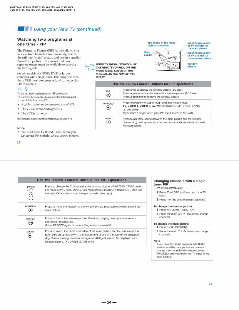
Use the Yellow Labeled Buttons for PIP Operations.
PIP
TV/VIDEO
AUDIO
REFER TO THE ILLUSTRATION OFTHE REMOTE CONTROL ON THEINSIDE FRONT COVER OF THISMANUAL AS YOU REVIEW THISCHART
Mainpicture
The sound of the mainpicture is received.
Input-source modeor TV channel forthe main picture
Input-source modeor TV channel forthe window picture
Windowpicture
The Picture-in-Picture (PIP) feature allows youto view two channels simultaneously, one inthe full size “main” picture and one in a smaller“window” picture. This means that twoseparate tuners must be available to providethe two signals.
Certain models (KV-27S45, 27V45 only) areequipped with a single tuner. This simply meansthat a VCR must be connected and turned on forPIP to operate.
Tip zTo ensure a correct single tuner PIP connection (KV-27S45, 27V45 only), make sure the following list is complete before using PIP:
• A cable or antenna is connected to the VCR• The VCR is connected to your TV• The VCR is turned on
(for detailed connection information, see pages 5-7)
Note• You must press TV (FUNCTION) before you
can control PIP with the yellow labeled buttons.
Press once to display the window picture (1/9 size).Press again to reduce the size of the window picture (1/16 size).Press a third time to remove the window picture.
Press repeatedly to step through available video inputs:TV, VIDEO 1, VIDEO 2, and VIDEO 3 (KV-27S45, 27S65, 27V45, 27V65 only)If you have a single tuner, your PIP input source is the VCR.
Press to alternate sound between the main picture and the windowpicture. A will appear for a few seconds to indicate which picture isreceiving sound.
Using your New TV (continued)
17
Press to change the TV channel in the window picture. (KV-27S65, 27V65 only)For models KV-27S45, 27V45, you must press VTR/DVD (FUNCTION), then usethe main CH +/- buttons to change channels. (see right)
Press to move the location of the window picture (counterclockwise) around themain picture.
Press to freeze the window picture. Great for copying down phone numbers,addresses, recipes, etc.Press FREEZE again to restore the previous screen(s).
Press to switch the audio and video of the main picture and the window picture.Each time you press SWAP, the picture and sound of the two will be swapped.Any channels being received through the AUX jack cannot be displayed as awindow picture. (KV-27S65, 27V65 only)
Use the Yellow Labeled Buttons for PIP Operations.
CH
–
+TV/VTR
POSITION
FREEZE
SWAP
Changing channels with a singletuner PIP• KV-27S45, 27V45 only
1 Press TV/VIDEO until you reach the TVinput.
2 Press PIP (the window picture appears).
To change the window picture:1 Press VTR/DVD (FUNCTION).
2 Press the main CH +/– buttons to changechannels.
To change the main picture:1 Press TV (FUNCTION).
2 Press the main CH +/– buttons to changechannels.
Note• If you have the same program in both the
window and the main picture and cannotchange the channel in the window; pressTV/VIDEO until you reach the TV input in themain picture.
Learning menu selectionUse the MENU button to access a menu anduse the select buttons (V or v) to alter settings.Use the following example, in which weactivate the CABLE, to learn how to modifysettings.
1 Press the MENU button.
The main menu appears.
2 Press V or v to highlight the desired menu(in this case SET UP ) and press toselect it.
MENU
3 Press V or v to move to the desired option.
4 Press .Options for your selection will bedisplayed.
5 Press V or v to make your selection andpress .
When you are finished making changes to theselected menu, choose MENU to return tothe main menu.
Notes• Pressing MENU on the remote control will
allow you to exit from the menus at anytime.
• If any menu items are "blacked out", pressthe ANT button on your remote controluntil a channel number appears.
VIDEOŁ
MODE: VIVID
PICTURE Ł
BRIGHTNESS
COLOR Ł
HUE
SHARPNESSŁ
MENU
MENUMove Select Exit
SET UP
CHANNEL SET UPŁ
FAVORITE CHANNELŁ
CHANNEL BLOCKŁ
VIDEO LABELŁ
CAPTION VISION:CC1
LANGUAGE: ENGLISH
MENU
Move Select Exit MENU
SET UP
CHANNEL SET UPŁ
FAVORITE CHANNELŁ
CHANNEL BLOCKŁ
VIDEO LABELŁ
CAPTION VISION:CC1
LANGUAGE: ENGLISH
MENU
Move Select Exit MENU
CHANNEL SET UPŁ
Ł
CABLE: OFFŁ
CHANNEL FIX: OFFŁ
AUTO PROGRAM
CHANNEL SKIP/ADDŁ
CHANNEL CAPTIONŁ
MENU
Move Select Exit
MENU
SET UP
CHANNEL SET UPŁ
FAVORITE CHANNELŁ
CHANNEL BLOCKŁ
VIDEO LABELŁ
CAPTION VISION:CC1Ł
LANGUAGE: ENGLISH
MENU
Move Select Exit MENU
CHANNEL SET UPŁ
Ł
CABLE: ONŁ
CHANNEL FIX: OFFŁ
AUTO PROGRAM
CHANNEL SKIP/ADDŁ
CHANNEL CAPTIONŁ
MENU
Move Select Exit
MENU
Using your Menus
19
MODECustomized picture
viewing
PICTUREPicture Adjustment
BRIGHTNESSPicture Adjustment
COLORPicture Adjustment
HUEPicture Adjustment
SHARPNESSPicture Adjustment
(except KV-20V80)VIVID: Select to receive a vivid, bright picture.STANDARD: Select to receive a standard picture.MOVIE: Select to receive a softened picture.
Adjust left to decrease picture contrast and soften the color.Adjust right to increase picture contrast and create more vivid color.
Adjust left to darken the picture.Adjust right to brighten the picture.
Adjust left to decrease color intensity.Adjust right to increase color intensity.
Adjust left to decrease the green tones.Adjust right to increase the green tones.
Adjust left to soften the picture.Adjust right to sharpen the picture.
MENU
Display Highlight Select
To restore the factory VIDEOsettingsPress RESET while the VIDEO menu isdisplayed.
Using the VIDEO menu
For detailed information on using the remoteto modify menu settings, refer to “Learningmenu selection” on page 18.
For detailed information on using the remoteto modify menu settings, refer to “Learningmenu selection” on page 18.
To select the AUDIO menu:
AUDIO
TREBLE Ł
BASS
BALANCE Ł
AUTO VOLUME: ON
SPEAKER: OFFŁ
AUDIO OUT: VARIABLE
OPTIONS
MENU
MENUMove Select Exit
MENU
Display Highlight Select
To restore the factory AUDIOsettingsPress RESET while the AUDIO menu isdisplayed.
Tip zPress for direct selection of an AUDIO setting.
Adjustmentbars
Adjust left or right to decrease or increase higher pitched sound
Adjust left or right to decrease or increase low pitched sounds.
Adjust left or right to emphasize speaker volume.
(KV-27V40, 27V45, 27V65 only).ON: Select to stabilize the volume when changing channels.OFF: Select to turn AUTO VOLUME off.
ON: Select to listen to the sound from the TV speakers and a separate stereosystem.
OFF: Select to turn off the TV speakers and listen to the TV's sound only throughexternal audio system speakers.
AUDIO OUT can only be set when speakers are set to OFF.VARIABLE: Sound output varies according to the TV settings.Useful when you want to use your remote control to control the output of aseparate audio system.FIXED: Sound output is held at a fixed level through your stereo.
Using your Menus (continued)
21
OPTIONSEnhanced audio
options
With the OPTIONS menu open:1 Press to access the feature you want to change.2 Press V or v to cycle through the options.MTS: Press V or v to select one of the following options:
STEREO: Select for stereo reception when viewing a broadcast in stereo.SAP: Select to listen to bilingual broadcast. (Non-SAP programs will be muted when this feature is selected.)MONO: Select for mono reception (use to reduce noise during stereo broadcasts.)
Quick MTS access: Press MTS on your remote control to cycle through the MTS options.
EFFECT: Press V or v to select one of these customized effects based on the program you are viewing:SRS: Produces a dynamic three dimensional sound for stereo audio signals.(KV-27V40, 27V45, 27V65 only)SURROUND: Simulates theater quality sound (only for stereo programs).(KV-20V80, 27S40, 27S45, 27S65 only)SIMULATED : Adds a surround-like effect to mono programs.(KV-27V40, 27V45, 27V65 only)
For detailed information on using the remoteto modify menu settings, refer to “Learningmenu selection” on page 18.
To select the TIMER menu:
MENU
Display Highlight Select
Tip zSet daylight saving time before setting the clock. Anyloss of power will cause these settings to be erased.
TIMERŁ
DAYLIGHT SAVING: YES
CURRENT TIME SET Ł
ON/OFF TIMER
MENU
MENUMove Select Exit
Spring: Select YES to compensate for Daylight Saving Time.The current time automatically moves one hour ahead.Fall: Select NO at the end of Daylight Saving Time.The current time moves back one hour.
CURRENT TIME SET menu will appear.1 Press .2 Press V or v until the current day is displayed. Press
to select.3 Press V or v until the current hour and AM/PM is
displayed. Press to select.4 Press V or v until the current minute is displayed,
press .The clock is set. Press MENU to exit.
ON/OFF TIMER menu will appear.1 Press .2 Press V or v until the desired day or range of days
is displayed. Press to select.3 Indicate the time that you want the TV to turn on by
pressing V or v and then .4 Set the time duration (maximum of 6 hours) by
pressing V or v and then .5 Press V or v until you reach the desired channel.
Press to select.The ON/OFF TIMER is now set. Press MENU to exit.When you perform AUTO PROGRAM, all ON/OFF TIMER settings will be erased.
CURRENT TIME SETŁ
Ł
___--:-- AMŁ
MENU
Move Select Exit MENU
ON/OFF TIMERŁ
Ł
___Ł
--:-- AM_h CH____Ł
MENUŁ
SUN 12:00 AM
Move Select Exit
MENU
Using your Menus (continued)
To cancel the ON/OFF TIMERfunctionPress RESET while the TIMER menu isdisplayed.
23
CHANNELSET UPBasic set up
options for
viewing
With the CHANNEL SET UP menu open:1 Use V or v to access the feature you want to change.2 Press to select the feature.CABLE: Select ON if your TV is connected to a cable
system. (After setting CABLE, you will need to runAUTO PROGRAM.)
CHANNEL FIX: Press and then use the V or v buttons to set the TV's inputto one of the following options:2-6: When a cable box is connected to the VHF/UHF input. Press DBS/CABLE(FUNCTION) and then CH +/– to change channels.AUX 2-6: When a cable box is connected to AUX and a cable or antenna isconnected to VHF/UHF. You can alternate between the two inputs by pressingANT on the remote control. (KV-27S65, 27V65 only)VIDEO 1: When you have connected video equipment (e.g. A/V receiver) andyou want the TV input fixed to it. You will be able to alternate between videosources using the A/V receiver.OFF: When you want to switch CHANNEL FIX off.Press ANT on the remote control until you reach a picture.
ON/OFF TIMER and CHANNEL BLOCK settings will be erased whenCHANNEL FIX is set.
AUTO PROGRAM: Instructs the TV to automatically program all receivablechannels.
CHANNEL SKIP/ADD:With the CHANNEL SKIP/ADD window open:1 Place the cursor next to SKIP or ADD. (only
one option will be displayed)2 Choose the desired channel using CH +/–, or
by selecting with the 0-9 buttons and pressingENTER.
3 Press to activate.
Using the SET UP menu
For detailed information on using the remoteto modify menu settings, refer to “Learningmenu selection” on page 18.
To select the SET UP menu:
MENU
Display Highlight Select
Notes• The FAVORITE CHANNEL feature is not
available for the AUX input.• Your remote control can be programmed to
.CHANNEL CAPTION: You will be able to label up to 12
channels with their call letters.(except KV-20V80)With the CHANNEL CAPTION menu open:1 Press and then V or v to access the desired
channel, and press again.2 Press V or v to display the first letter or number
of the caption and press to select it.3 Press to activate. To erase a caption, press RESET.
You will be able to block two channels.With the CHANNEL BLOCK window open:1 Choose 1 or 2 and press .2 Press V or v to display the channel you want to
block.3 Press to activate.
When you select the blocked channel, BLOCKEDwill appear on the screen. CAPTION VISION will also be blocked.
When you perform AUTO PROGRAM, your CHANNEL BLOCK settings will be erased.
CHANNEL CAPTIONŁ
- ___Ł
____
MENUŁ
Move Select Exit MENU
Using your Menus (continued)
Using the SET UP menu(continued)
For detailed information on using the remoteto modify menu settings, refer to “Learningmenu selection” on page 18.
To select the SET UP menu:
MENU
Display Highlight Select
SET UP
CHANNEL SET UPŁ
FAVORITE CHANNELŁ
CHANNEL BLOCKŁ
VIDEO LABELŁ
CAPTION VISION:CC1
LANGUAGE: ENGLISH
MENU
Move Select Exit MENU
To erase the CHANNEL BLOCKsettingsPress RESET while the SET UP menu isdisplayed.
CHANNEL BLOCKŁ
Ł
1.CH___Ł
2.CH___Ł
MENU
Select a program
Move Select Exit MENU
25
FAVORITECHANNELQuick access to
favorite channels
VIDEO LABELEasy recognition of
connected equipment
(e.g. DBS, VHS, etc.)
LANGUAGE
Setting FAVORITE CHANNEL:1 Press and then V or v to select AUTO or MANUAL. (Selecting AUTO will display the last five channels
chosen with the remote control.)2 Press V or v to move the cursor to 1, 2, 3, 4 or 5 and press .3 Press V or v to access the desired channel and press .4 For KV-27S65, 27V65 only, you can preview your favorite channels in the window picture, to do so, set
PREVIEW to ON.Using FAVORITE CHANNEL:1 Press when in normal viewing mode. Your FAVORITE CHANNEL options will appear.2 Press V or v to access the channel you want to watch, and press .3 For models KV-27S65, 27V65 only, if PREVIEW is ON, a window picture displays your favorite channels as you cycle
through the options.
This feature allows you to label each input mode so that you can easily identify connected equipment (e.g. youcan label VIDEO 1 as VHS). (except KV-20V80)With the VIDEO LABEL window open:1 Press V or v to move to the input mode you want to label and press .2 Press V or v to choose the label and press .
VIDEO LABEL Options:Video 1: VHS, 8mm, BETA, LD, GAME, DBS, DVD, WEB, RECEIVER, DTV.Video 2/3: VHS, 8mm, BETA, LD, GAME, DBS, DVD, WEB, RECEIVER, DTV.When VIDEO LABEL is set to WEB, the picture will darken, creating an ideal picture for WebTV viewing.
(except Canadian models)You can change the language of your menus to either ENGLISH or ESPAÑOL.
Buttons on the remotecontrolPress VTR/DVD (POWER).Press (.Press p.Press P.To resume normal playback,press again or press (.Press ) or 0 duringplayback.To resume normal playback,press (.Press CH +/–.
Programming the remoteYou can program the supplied remote controlto operate a cable box or DBS receiver.
1 Press CODE SET.
2 Press DBS/CABLE (FUNCTION).
3 Use the 0-9 buttons to key in themanufacturer's code number from thefollowing chart.
4 Press ENTER.
For more details on operating thecable box or DBS receiver
Refer to the operating instructions that weresupplied with the equipment.
If the remote control doesn’t work
• First, try repeating the setup proceduresusing the other codes listed for yourequipment.
Tips z• If more than one code number is listed, try entering
them one by one until you come to the correct code foryour equipment.
• If you enter a new code number, the code number youpreviously entered at that setting is erased.
• In some rare cases, you may not be able to operateyour equipment with the supplied remote control. Inthis case, use the equipment’s own remote controlunit.
• Whenever you remove the batteries the code numbersmay revert to the factory setting and must be reset.
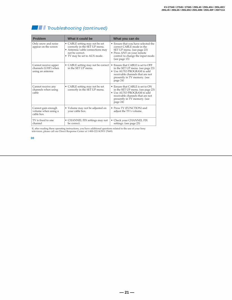
If, after reading these operating instructions, you have additional questions related to the use of your Sonytelevision, please call our Direct Response Center at 1-800-222-SONY (7669).
• Ensure that you have selected thecorrect CABLE mode in theSET UP menu. (see page 23)
• Press ANT on your remotecontrol to change the input mode.(see page 15)
• Ensure that CABLE is set to OFFin the SET UP menu. (see page 23)
• Use AUTO PROGRAM to addreceivable channels that are notpresently in TV memory. (seepage 24)
• Ensure that CABLE is set to ONin the SET UP menu. (see page 23)
• Use AUTO PROGRAM to addreceivable channels that are notpresently in TV memory. (seepage 24)
• Press TV (FUNCTION) andadjust the TV's volume.
• Check your CHANNEL FIXsettings. (see page 23)
• CABLE setting may not be setcorrectly in the SET UP menu.
• Antenna/cable connections maynot be correct.
• TV may be set to AUX mode.
• CABLE setting may not be correctin the SET UP menu.
• CABLE setting may not be setcorrectly in the SET UP menu.
• Volume may not be adjusted onyour cable box.
• CHANNEL FIX settings may notbe correct.
Only snow and noiseappear on the screen
Cannot receive upperchannels (UHF) whenusing an antenna
Do not use sharp objects which may cause damage to the sur-face of the anode-cap.
Do not squeeze the rubber covering too hard to avoid damag-ing the anode-cap. A material fitting called a shatter-hook ter-minal is built into the rubber.
Do not force turn the foot of the rubber cover. This may causethe shatter-hook terminal to protrude and damage the rubber.
HOW TO HANDLE AN ANODE-CAP
Turn up one side of the rubber cap inthe direction indicated by arrow .
When one side of the rubber cap sepa-rates from the anode button, the anode-cap can be removed by turning the rub-ber cap and pulling it in the direction ofarrow .
Use your thumb to pull the rubber capfirmly in the direction indicated byarrow .
REMOVAL OF THE ANODE-CAPNOTE: Short circuit the anode of the picture tube and the anode cap to the metal chassis, CRT shield or carbon painted on the CRT, afterremoving the anode.
REMOVAL PROCEDURES
WARNING Before removing anode cap:
H.V. remains in the CRT even after the power is disconnected.
To avoid electrical shock, discharge CRT before attempting to remove the anodecap : Short between anode and CRT coating earth ground strap. Coating earth
The following adjustments should be made when a complete realignment is required or a new picture tube is installed. These adjustments should be performed with rated power supply voltage unless otherwise noted.
The controls and switch should be set as followsunless otherwise noted:
PICTURE control ................. normal
BRIGHTNESS control ......... normal
3-1. BEAM LANDING
Preparation:
• Feed in the white pattern signal.• Before starting, degauss the entire screen.
1. Input a raster signal with the pattern generator.
2. Loosen the deflection yoke mounting screw, and set thepurity control to the center as shown in Fig.2.
3. Turn the raster signal of the pattern generator togreen.
4. Move the deflection yoke backward, and adjust with thepurity control so that green is in the center and red andblue are at the sides evenly. (Fig.3)
5. Move the deflection yoke forward, and adjust so that theentire screen becomes green. (Fig.1)
6. Switch over the raster signal to red and blue and confirmthe condition.
7. When the position of the deflection yoke is determined,tighten it with the deflection yoke mounting screw.
8. When landing at the corner is not right, adjust by usingthe disk magnets. (Fig.4)
Perform the adjustments in order as follows:
1. Beam Landing2. Convergence3. Focus4. Screen (G2) and White Balance
Note: Test Equipment Required
1. Color Bar Pattern Generator2. Degausser3. DC Power Supply4. Digital Multimeter
Disk magnets orrotatable diskmagnets correctthese areas (a-d).
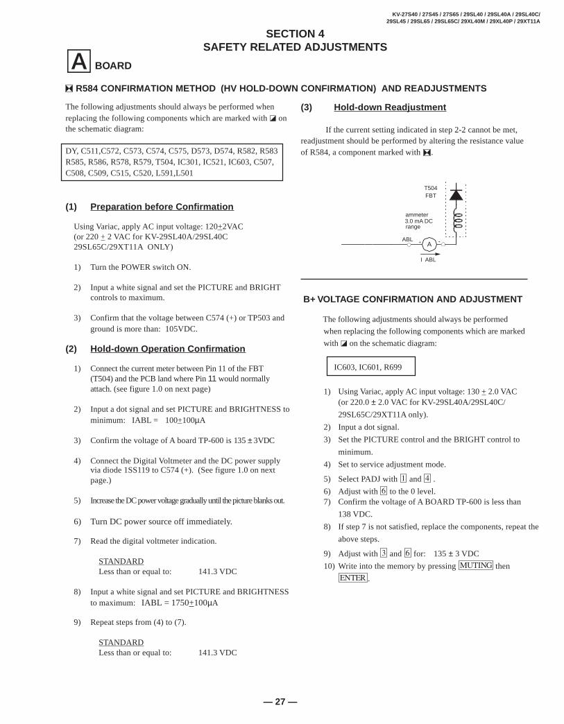
Using Variac, apply AC input voltage: 120+2VAC(or 220 + 2 VAC for KV-29SL40A/29SL40C29SL65C/29XT11A ONLY)
1) Turn the POWER switch ON.
2) Input a white signal and set the PICTURE and BRIGHTcontrols to maximum.
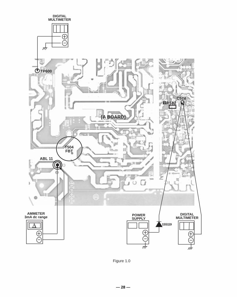
3) Confirm that the voltage between C574 (+) or TP503 andground is more than: 105VDC.
(2) Hold-down Operation Confirmation
1) Connect the current meter between Pin 11 of the FBT(T504) and the PCB land where Pin 11 would normallyattach. (see figure 1.0 on next page)
2) Input a dot signal and set PICTURE and BRIGHTNESS tominimum: IABL = 100+100µA
3) Confirm the voltage of A board TP-600 is 135 ± 3VDC
4) Connect the Digital Voltmeter and the DC power supplyvia diode 1SS119 to C574 (+). (See figure 1.0 on nextpage.)
5) Increase the DC power voltage gradually until the picture blanks out.
6) Turn DC power source off immediately.
7) Read the digital voltmeter indication.
STANDARDLess than or equal to: 141.3 VDC
8) Input a white signal and set PICTURE and BRIGHTNESSto maximum: IABL = 1750+100µA
9) Repeat steps from (4) to (7).
STANDARDLess than or equal to: 141.3 VDC
SECTION 4SAFETY RELATED ADJUSTMENTS
The following adjustments should always be performed
when replacing the following components which are marked
with ] on the schematic diagram:
IC603, IC601, R699
1) Using Variac, apply AC input voltage: 130 + 2.0 VAC(or 220.0 ± 2.0 VAC for KV-29SL40A/29SL40C/
29SL65C/29XT11A only).
2) Input a dot signal.
3) Set the PICTURE control and the BRIGHT control to
minimum.
4) Set to service adjustment mode.
5) Select PADJ with and .
6) Adjust with to the 0 level.7) Confirm the voltage of A BOARD TP-600 is less than
138 VDC.
8) If step 7 is not satisfied, replace the components, repeat the
above steps.
9) Adjust with and for: 135 ± 3 VDC
10) Write into the memory by pressing then
.
B+ VOLTAGE CONFIRMATION AND ADJUSTMENT
(3) Hold-down Readjustment
If the current setting indicated in step 2-2 cannot be met,readjustment should be performed by altering the resistance valueof R584, a component marked with .
+
I ABL
ABL
T504FBT
range
-
ammeter3.0 mA DC
A
R584 CONFIRMATION METHOD (HV HOLD-DOWN CONFIRMATION) AND READJUSTMENTS
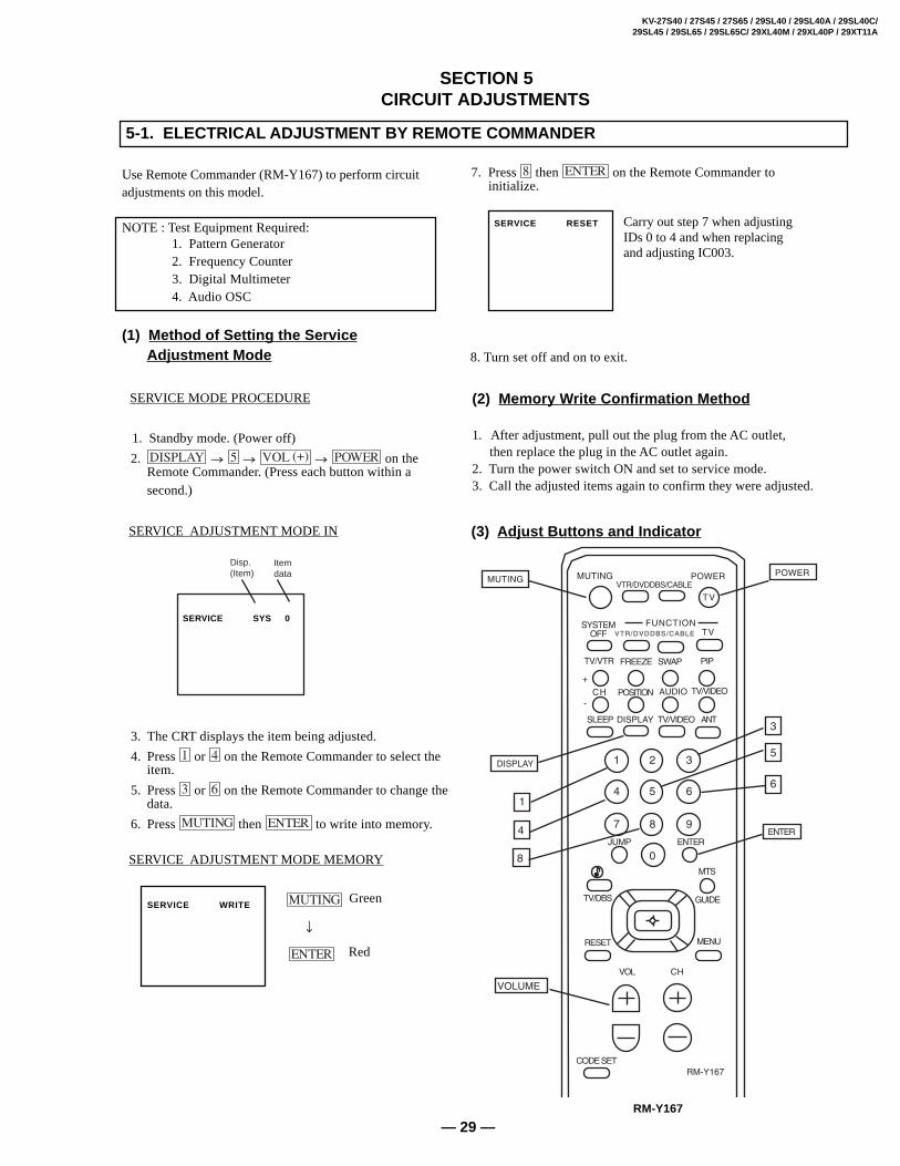
7. Press then on the Remote Commander to initialize.
Carry out step 7 when adjustingIDs 0 to 4 and when replacingand adjusting IC003.
SERVICE RESET
8. Turn set off and on to exit.
(3) Adjust Buttons and Indicator
Use Remote Commander (RM-Y167) to perform circuitadjustments on this model.
NOTE : Test Equipment Required:1. Pattern Generator2. Frequency Counter3. Digital Multimeter4. Audio OSC
(1) Method of Setting the ServiceAdjustment Mode
SERVICE MODE PROCEDURE
1. Standby mode. (Power off)
2. on theRemote Commander. (Press each button within asecond.)
SERVICE ADJUSTMENT MODE IN
3. The CRT displays the item being adjusted.
4. Press or on the Remote Commander to select theitem.
5. Press or on the Remote Commander to change thedata.
6. Press then to write into memory.
SERVICE ADJUSTMENT MODE MEMORY
GreenSERVICE WRITE
Red
(2) Memory W rite Confirmation Method
1. After adjustment, pull out the plug from the AC outlet, then replace the plug in the AC outlet again.2. Turn the power switch ON and set to service mode.3. Call the adjusted items again to confirm they were adjusted.
R ON . . . . . . . . . . . ON (1)G ON . . . . . . . . . . . ON (1)
B ON . . . . . . . . . . . ON (1)
(5) Feature ID Map
5-2. A BOARD ADJUSTMENTS
H. FREQUENCY ADJUSTMENT
1. Input a monoscope signal.2. Set to Service adjustment Mode.3. Connect a frequency counter to base of Q501
(TP-500 H. DRIVE).4. Select the item of AFC, set to 3 level (free run).5. Check H. Frequency for the 15735 ± 200 Hz. (NTSC) or
check H. Frequency for the 15650 ± 200 Hz. (Trinorma)6. Select the item of AFC again, adjust the level "0".7. Write into the memory by pressing
then .
V. FREQUENCY ADJUSTMENT
1. Select video 1 with no signal input. 2. Set the conditions with standard setting.
3. Connect the frequency counter across TP-508 or CN501VDY (+) pin 6 connector and ground.
4. Check V. Frequency for the 60 ± 2 Hz (NTSC)5. Check V. Frequency for the 50 ± 2 Hz (Trinorma).
SUB CONTRACT ADJUSTMENT (SCON)
1. Input a color-bar signal. 2. Select the red color. 3. Set to Service adjustment Mode. 4. Select the item DCOL to "0" level. 5. Set the conditions as follows.
Note : Perform this adjustment after checking H. FREQUENCY.
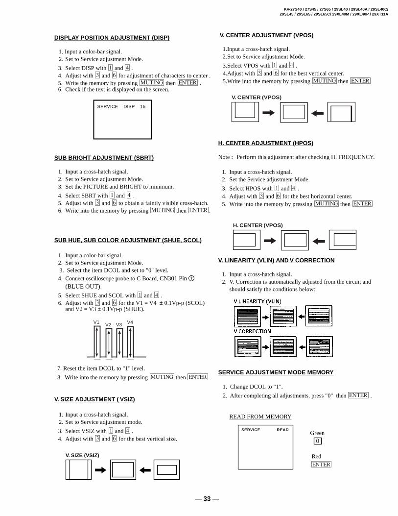
1. Input a cross-hatch signal.2. Set the Service adjustment Mode.
3. Select HPOS with and .4. Adjust with and for the best horizontal center.5. Write into the memory by pressing then
V. LINEARITY (VLIN) AND V CORRECTION
1. Input a cross-hatch signal.2. V. Correction is automatically adjusted from the circuit and
should satisfy the conditions below:
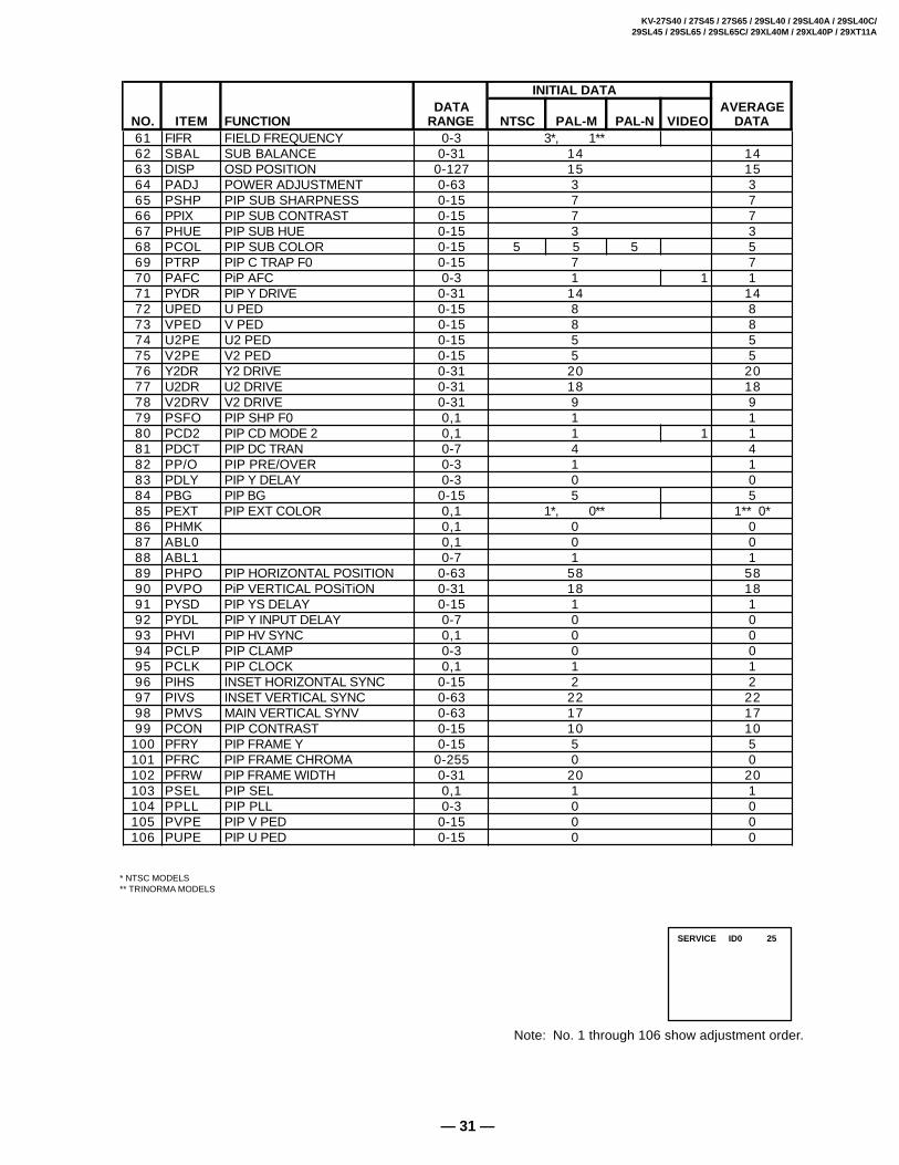
…
SERVICE ADJUSTMENT MODE MEMORY
1. Change DCOL to "1".
2. After completing all adjustments, press "0" then .
/
/
V. SIZE (VSIZ)
DISPLAY POSITION ADJUSTMENT (DISP)
1. Input a color-bar signal. 2. Set to Service adjustment Mode.
3. Select DISP with and .4. Adjust with and for adjustment of characters to center .5. Write the memory by pressing then .6. Check if the text is displayed on the screen.
SUB BRIGHT ADJUSTMENT (SBR T)
1. Input a cross-hatch signal.2. Set to Service adjustment Mode.3. Set the PICTURE and BRIGHT to minimum.
4. Select SBRT with and .5. Adjust with and to obtain a faintly visible cross-hatch.6. Write into the memory by pressing then .
SUB HUE, SUB COLOR ADJUSTMENT (SHUE, SCOL)
1. Input a color-bar signal.2. Set to Service adjustment Mode.
3. Select the item DCOL and set to "0" level.
4. Connect oscilloscope probe to C Board, CN301 Pin 7(BLUE OUT).
5. Select SHUE and SCOL with and .6. Adjust with and for the V1 = V4 ± 0.1Vp-p (SCOL)
and V2 = V3 ± 0.1Vp-p (SHUE).
V1 V2 V3 V4
7. Reset the item DCOL to "1" level.
8. Write into the memory by pressing then .
V. SIZE ADJUSTMENT ( VSIZ)
1. Input a cross-hatch signal. 2. Set to Service adjustment mode.
3. Select VSIZ with and .4. Adjust with and for the best vertical size.
/ ?
H. CENTER (VPOS)
/ ?
V. CENTER (VPOS)
READ FROM MEMORY
Green 0
SERVICE READ
Red
SERVICE DISP 15
V. CENTER ADJUSTMENT (VPOS)
1.Input a cross-hatch signal. 2.Set to Service adjustment Mode.
3.Select VPOS with and . 4.Adjust with and for the best vertical center. 5.Write into the memory by pressing then
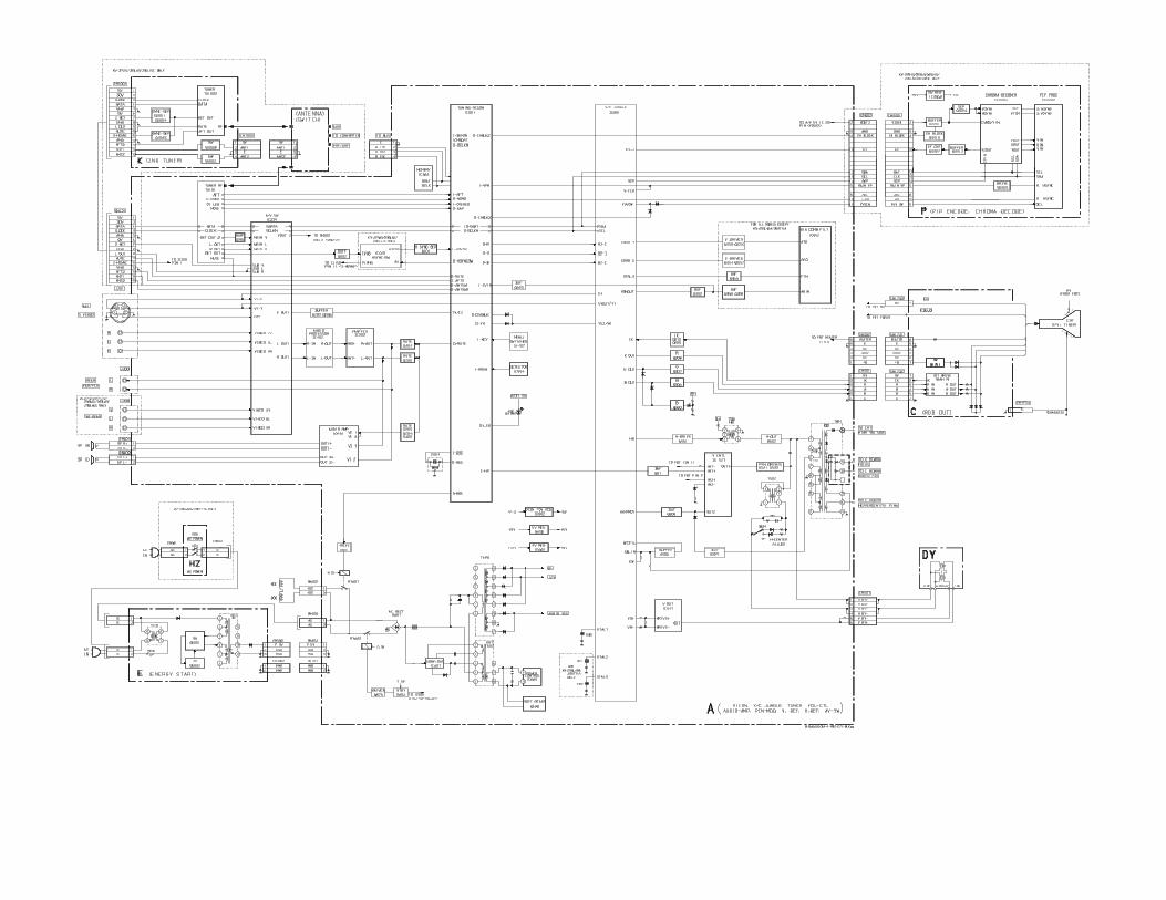
• All voltages are in V.• Voltage is DC with respect to ground unless otherwise noted.• Readings are taken with a 10MΩ digital multimeter.• Readings are taken with a color-bar signal input.• Voltage variations may be noted due to normal produc- tion tolerance.• Circled numbers are waveform references.
• : B + Line
• : B - Line
• m : signal path
Reference Information RESISTOR : RN METAL FILM
: RC SOLID: FPRD NON FLAMMABLE CARBON: FUSE NON FLAMMABLE FUSIBLE: RW NON FLAMMABLE WIREWOUND: RS NON FLAMMABLE METAL OXIDE: RB NON FLAMMABLE CEMENT: ADJUSTMENT RESISTOR
COIL : LF-8L MICRO INDUCTOR CAPACITOR : TA TANTALUM
: PS STYROL: PP POLYPROPYLENE: PT MYLAR: MPS METALIZED POLYESTER: MPP METALIZED POLYPROPYLENE: ALB BIPOLAR: ALT HIGH TEMPERATURE: ALR HIGH RIPPLE
- - - - -
Pitch: 5mm Rating electrical power 1/4W
• All resistors are in ohms.
KΩ=1000Ω, MΩ=1000KΩ
• f nonflammable resistor.
• ∆: internal component.
• p: panel designation and adjustment for repair.
• All variable and adjustable resistors have charac- teristic curve B, unless otherwise noted.
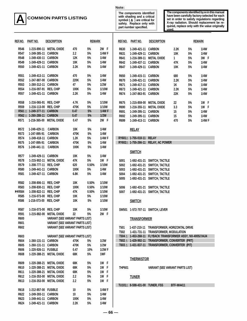
• The components identified by ] in this manual have been carefully factory-selected for each set in order to satisfy regulations regarding X-ray radiation. Should replacement be required, replace only with the value originally used.
• When replacing components identified by ] make the necessary adjustments indicated. If results do not meet the specified value, change the component identified by [ and repeat the adjustment until the specified value is achieved. (Refer to R584 on page 27 and 28).
• When replacing parts in the table below be sure to perform the related adjustment.
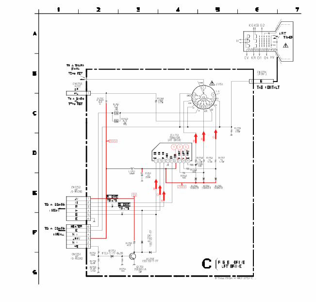
6-3. Printed Wiring Boards and SchematicDiagrams
Note:• All capacitors are in µF unless otherwise noted. pF: µµF 50WV or less are not indicated except for electrolytic and tantalums.• All electrolytics are 50V unless otherwise specified• Indication of resistance, which does not have one for rating electrical power, is as follows:
Adjustment ([)
HV HOLD-DOWN (R584)
B+ VOLTAGECONFIRMATION
— 38 —
Note: The symbol G display is on the component side.
The components identified by shading and mark ¡¡¡¡¡ arecritical for safety. Replace only with part numberspecified.
The symbol G indicates fast operating fuse. Replace only with fuse of same rating as marked.
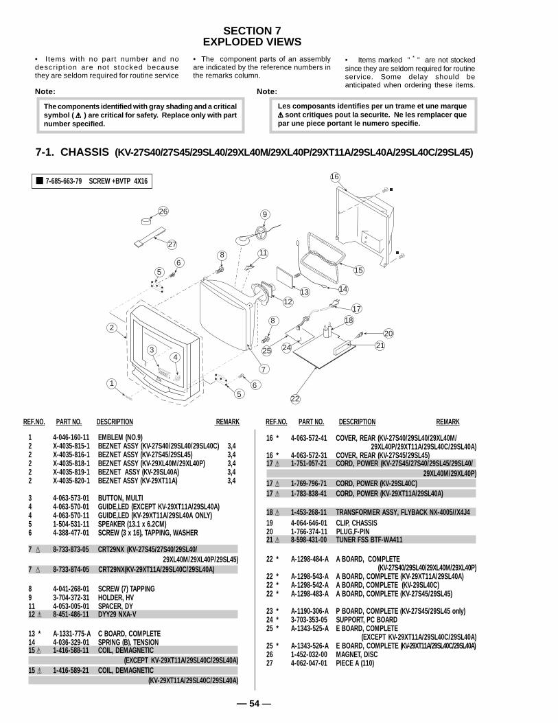
• Items marked " * " are not stockedsince they are seldom required for routineservice. Some delay should beanticipated when ordering these items.
• Items with no part number and nodescript ion are not stocked becausethey are seldom required for routine service
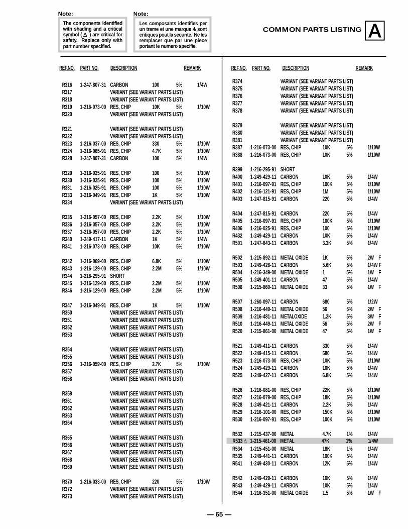
The components identified with gray shading and a criticalsymbol ( ¡¡¡¡¡ ) are critical for safety. Replace only with partnumber specified.
Note:
Les composants identifies per un trame et une marque¡¡¡¡¡ sont critiques pout la securite. Ne les remplacer quepar une piece portant le numero specifie.
Note:
• The component parts of an assemblyare indicated by the reference numbers inthe remarks column.
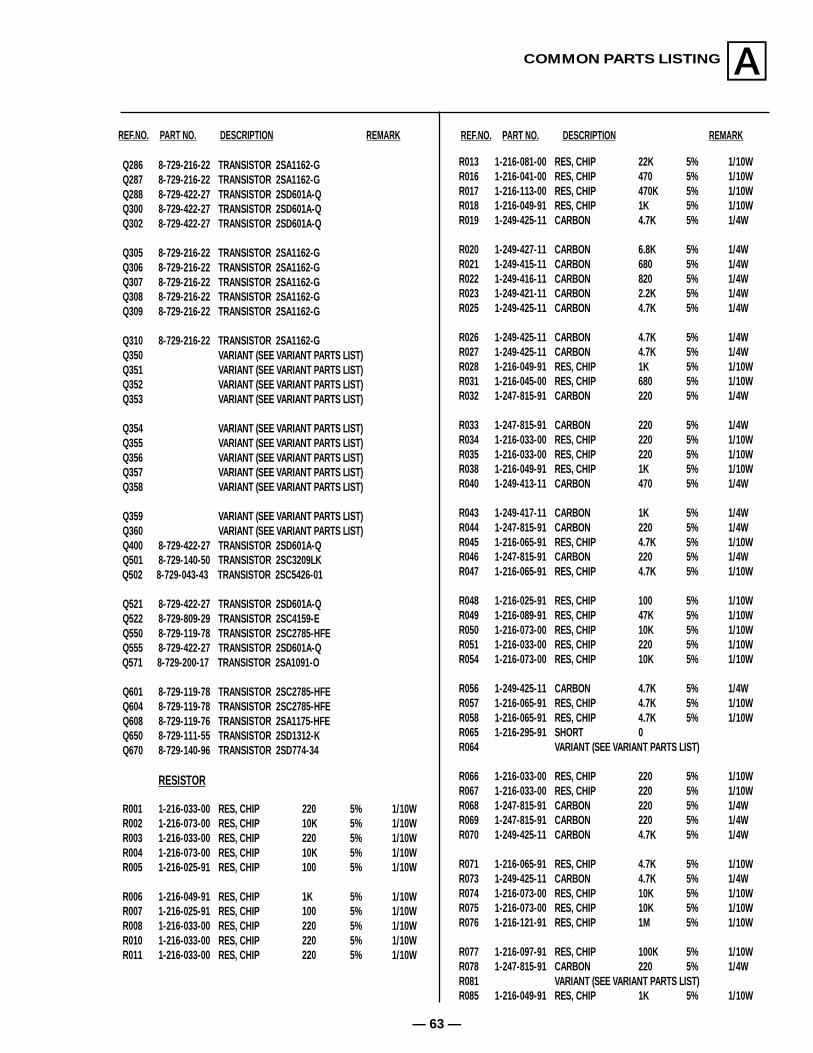
REF.NO. PART NO. DESCRIPTION REMARK REF.NO. PART NO. DESCRIPTION REMARK
REF.NO. PART NO. DESCRIPTION REMARK REF.NO. PART NO. DESCRIPTION REMARK
7-2. CHASSIS (KV-27S65/29SL65/29SL65C)
• Items marked " * " are not stockedsince they are seldom required for routineservice. Some delay should beanticipated when ordering these items.
• Items with no part number and nodescript ion are not stocked becausethey are seldom required for routine service
The components identified with gray shading and a criticalsymbol ( ¡¡¡¡¡ ) are critical for safety. Replace only with partnumber specified.
Note:
Les composants identifies per un trame et une marque¡¡¡¡¡ sont critiques pout la securite. Ne les remplacer quepar une piece portant le numero specifie.
Note:
• The component parts of an assemblyare indicated by the reference numbers inthe remarks column.
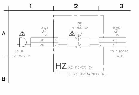
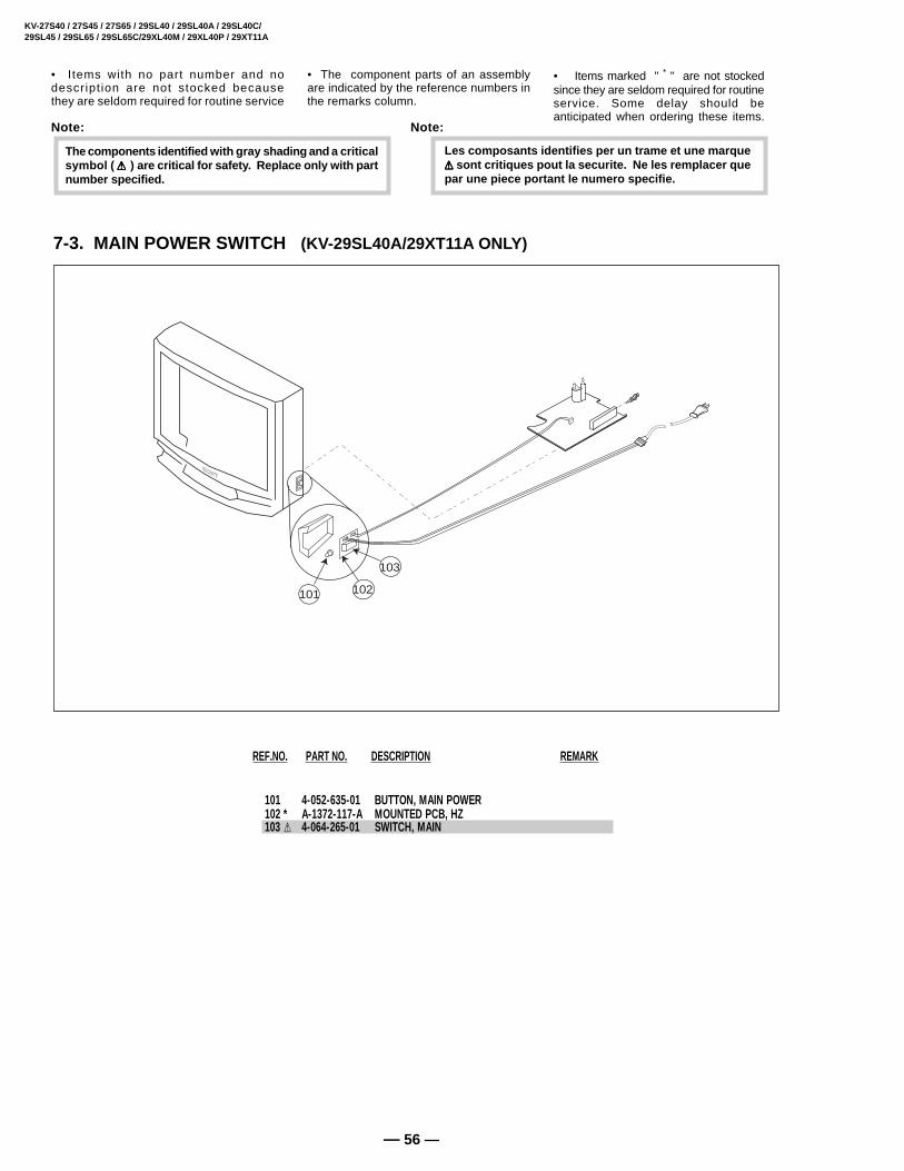
101 4-052-635-01 BUTTON, MAIN POWER 102 * A-1372-117-A MOUNTED PCB, HZ 103 ¡ 4-064-265-01 SWITCH, MAIN
• Items marked " * " are not stockedsince they are seldom required for routineservice. Some delay should beanticipated when ordering these items.
• Items with no part number and nodescript ion are not stocked becausethey are seldom required for routine service
The components identified with gray shading and a criticalsymbol ( ¡¡¡¡¡ ) are critical for safety. Replace only with partnumber specified.
Note:
Les composants identifies per un trame et une marque¡¡¡¡¡ sont critiques pout la securite. Ne les remplacer quepar une piece portant le numero specifie.
Note:
• The component parts of an assemblyare indicated by the reference numbers inthe remarks column.
101 102
103
REF.NO. PART NO. DESCRIPTION REMARK
— 57 —
REF.NO. PART NO. DESCRIPTION REMARKREF.NO. PART NO. DESCRIPTION REMARK
COMMON PARTS LISTINGA
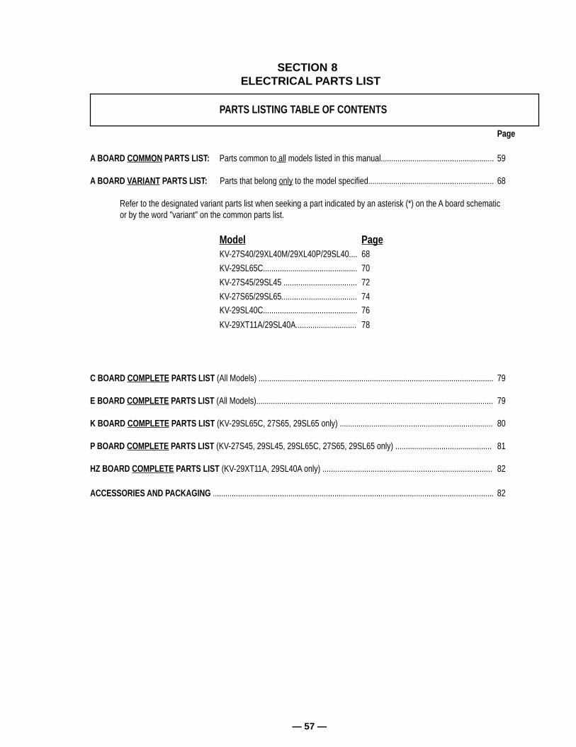
PARTS LISTING TABLE OF CONTENTS
Page
A BOARD COMMON PARTS LIST: Parts common to all models listed in this manual...................................................... 59
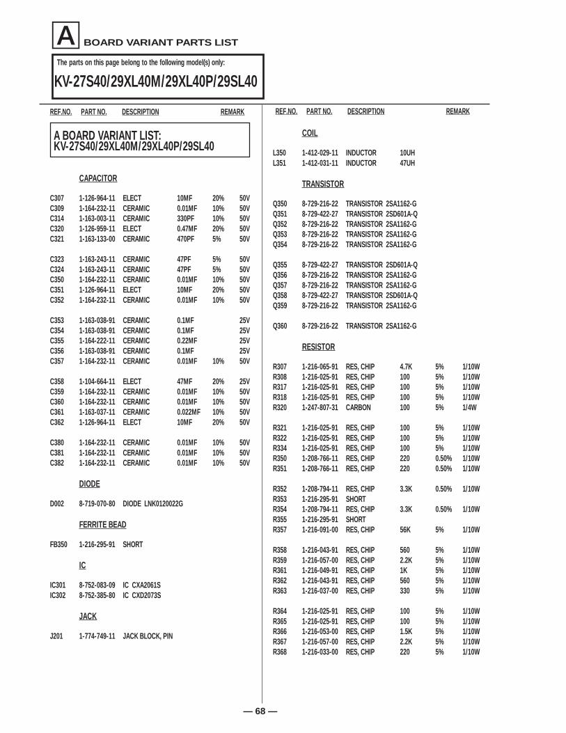
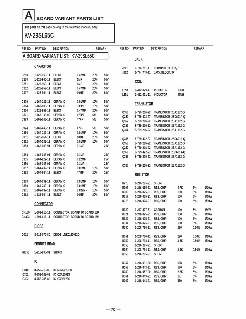
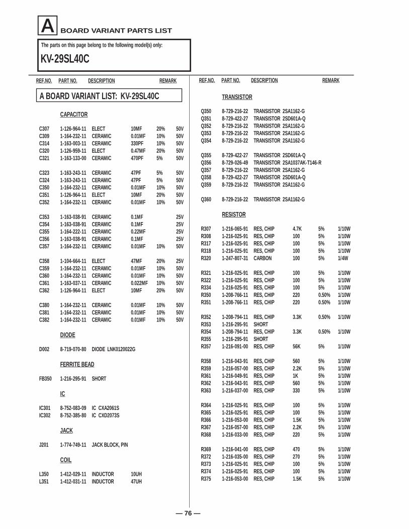
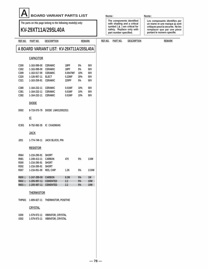
A BOARD VARIANT PARTS LIST: Parts that belong only to the model specified............................................................ 68
Refer to the designated variant parts list when seeking a part indicated by an asterisk (*) on the A board schematicor by the word "variant" on the common parts list.
C BOARD COMPLETE PARTS LIST (All Models) ................................................................................................................ 79
E BOARD COMPLETE PARTS LIST (All Models)................................................................................................................. 79
K BOARD COMPLETE PARTS LIST (KV-29SL65C, 27S65, 29SL65 only) ......................................................................... 80
P BOARD COMPLETE PARTS LIST (KV-27S45, 29SL45, 29SL65C, 27S65, 29SL65 only) .............................................. 81
HZ BOARD COMPLETE PARTS LIST (KV-29XT11A, 29SL40A only) ................................................................................. 82
ACCESSORIES AND PACKAGING ...................................................................................................................................... 82
SECTION 8 ELECTRICAL PARTS LIST
— 59 —
REF.NO. PART NO. DESCRIPTION REMARKREF.NO. PART NO. DESCRIPTION REMARK
COMMON PARTS LISTINGA
REF.NO. PART NO. DESCRIPTION REMARKREF.NO. PART NO. DESCRIPTION REMARK
A * A-1298-484-A A BOARD, COMPLETE (KV-27S40/29XL40M/29XL40P/29SL40) * A-1298-485-A A BOARD, COMPLETE (KV-29SL65C) * A-1298-483-A A BOARD, COMPLETE (KV-27S45/29SL45) * A-1298-541-A A BOARD, COMPLETE (KV-27S65/29SL65) * A-1298-542-A A BOARD, COMPLETE (KV-29SL40C) * A-1298-543-A A BOARD, COMPLETE (KV-29XT11A/29SL40A)
C225 1-163-017-00 CERAMIC CHIP 0.0047MF 10% 50VC250 VARIANT (SEE VARIANT PARTS LIST)C251 VARIANT (SEE VARIANT PARTS LIST)C252 VARIANT (SEE VARIANT PARTS LIST)C255 1-104-760-11 CERAMIC CHIP 0.047MF 10% 50V
• Items marked " * " are not stocked since they are seldom required for routine service. Some delay should be anticipated when ordering these items.
• All variable and adjustable resistors have characteristic curve B, unless otherwise noted.
RESISTORS• All resistors are in ohms
• F : nonflammable
CAPACITORS• MF = µF
INDUCTORS• UH = µH, MMH = mH
When indicating parts by referencenumber, please include the board name.
The components identified by [ in this manualhave been carefully factory-selected for eachset in order to satisfy regulations regarding X-ray radiation. Should replacement be required,replace only with the value originally used.
The components identified by shadingand mark ¡¡¡¡¡ are critical for safety.Replace only with part number specified.
Note:
Note:
Les composants identifies per un trameet une marque ¡¡¡¡¡ sont critiques pour lasecurite. Ne les remplacer que par unepiece portant le numero specifie.
COMMON PARTS LISTINGA
— 60 —
REF.NO. PART NO. DESCRIPTION REMARK REF.NO. PART NO. DESCRIPTION REMARK
C318 1-164-232-11 CERAMIC CHIP 0.01MF 10% 50VC319 1-126-963-11 ELECT 4.7MF 20% 50VC320 VARIANT (SEE VARIANT PARTS LIST)C321 VARIANT (SEE VARIANT PARTS LIST)C323 VARIANT (SEE VARIANT PARTS LIST)
C324 VARIANT (SEE VARIANT PARTS LIST)C325 1-102-110-00 CERAMIC 220PF 10% 50VC330 1-163-003-11 CERAMIC CHIP 330PF 10% 50VC331 1-163-005-11 CERAMIC CHIP 470PF 10% 50VC350 VARIANT (SEE VARIANT PARTS LIST)
C351 VARIANT (SEE VARIANT PARTS LIST)C352 VARIANT (SEE VARIANT PARTS LIST)C353 VARIANT (SEE VARIANT PARTS LIST)C354 VARIANT (SEE VARIANT PARTS LIST)C355 VARIANT (SEE VARIANT PARTS LIST)
C356 VARIANT (SEE VARIANT PARTS LIST)C357 VARIANT (SEE VARIANT PARTS LIST)C358 VARIANT (SEE VARIANT PARTS LIST)C359 VARIANT (SEE VARIANT PARTS LIST)C360 VARIANT (SEE VARIANT PARTS LIST)
C361 VARIANT (SEE VARIANT PARTS LIST)C362 VARIANT (SEE VARIANT PARTS LIST)C370 1-164-232-11 CERAMIC CHIP 0.01MF 10% 50VC371 1-164-232-11 CERAMIC CHIP 0.01MF 10% 50V
C377 1-126-964-11 ELECT 10MF 20% 50VC380 VARIANT (SEE VARIANT PARTS LIST)C381 VARIANT (SEE VARIANT PARTS LIST)C382 VARIANT (SEE VARIANT PARTS LIST)C390 1-126-959-11 ELECT 0.47MF 20% 50V
IC001 8-759-496-18 IC M37273MF-XXXSPIC002 8-759-371-21 IC MM1319AFBEIC003 8-759-353-44 IC ST24C08FM6TRIC004 8-742-014-11 HYB IC SBX1981-51IC010 VARIANT (SEE VARIANT PARTS LIST)
IC202 8-759-100-96 IC UPC4558G2IC203 8-759-534-81 IC MM1313ADIC301 VARIANT (SEE VARIANT PARTS LIST)
IC302 VARIANT (SEE VARIANT PARTS LIST)IC401 8-759-490-17 IC TDA7057AQ/N2
Q310 8-729-216-22 TRANSISTOR 2SA1162-GQ350 VARIANT (SEE VARIANT PARTS LIST)Q351 VARIANT (SEE VARIANT PARTS LIST)Q352 VARIANT (SEE VARIANT PARTS LIST)Q353 VARIANT (SEE VARIANT PARTS LIST)
Q354 VARIANT (SEE VARIANT PARTS LIST)Q355 VARIANT (SEE VARIANT PARTS LIST)Q356 VARIANT (SEE VARIANT PARTS LIST)Q357 VARIANT (SEE VARIANT PARTS LIST)Q358 VARIANT (SEE VARIANT PARTS LIST)
Q359 VARIANT (SEE VARIANT PARTS LIST)Q360 VARIANT (SEE VARIANT PARTS LIST)Q400 8-729-422-27 TRANSISTOR 2SD601A-QQ501 8-729-140-50 TRANSISTOR 2SC3209LK
REF.NO. PART NO. DESCRIPTION REMARKREF.NO. PART NO. DESCRIPTION REMARK
COMMON PARTS LISTINGA
R316 1-247-807-31 CARBON 100 5% 1/4WR317 VARIANT (SEE VARIANT PARTS LIST)R318 VARIANT (SEE VARIANT PARTS LIST)R319 1-216-073-00 RES, CHIP 10K 5% 1/10WR320 VARIANT (SEE VARIANT PARTS LIST)
R321 VARIANT (SEE VARIANT PARTS LIST)R322 VARIANT (SEE VARIANT PARTS LIST)R323 1-216-037-00 RES, CHIP 330 5% 1/10WR324 1-216-065-91 RES, CHIP 4.7K 5% 1/10WR328 1-247-807-31 CARBON 100 5% 1/4W
R347 1-216-049-91 RES, CHIP 1K 5% 1/10WR350 VARIANT (SEE VARIANT PARTS LIST)R351 VARIANT (SEE VARIANT PARTS LIST)R352 VARIANT (SEE VARIANT PARTS LIST)R353 VARIANT (SEE VARIANT PARTS LIST)
R354 VARIANT (SEE VARIANT PARTS LIST)R355 VARIANT (SEE VARIANT PARTS LIST)R356 1-216-059-00 RES, CHIP 2.7K 5% 1/10WR357 VARIANT (SEE VARIANT PARTS LIST)R358 VARIANT (SEE VARIANT PARTS LIST)
R359 VARIANT (SEE VARIANT PARTS LIST)R361 VARIANT (SEE VARIANT PARTS LIST)R362 VARIANT (SEE VARIANT PARTS LIST)R363 VARIANT (SEE VARIANT PARTS LIST)R364 VARIANT (SEE VARIANT PARTS LIST)
R365 VARIANT (SEE VARIANT PARTS LIST)R366 VARIANT (SEE VARIANT PARTS LIST)R367 VARIANT (SEE VARIANT PARTS LIST)R368 VARIANT (SEE VARIANT PARTS LIST)R369 VARIANT (SEE VARIANT PARTS LIST)
R370 1-216-033-00 RES, CHIP 220 5% 1/10WR372 VARIANT (SEE VARIANT PARTS LIST)R373 VARIANT (SEE VARIANT PARTS LIST)
R374 VARIANT (SEE VARIANT PARTS LIST)R375 VARIANT (SEE VARIANT PARTS LIST)R376 VARIANT (SEE VARIANT PARTS LIST)R377 VARIANT (SEE VARIANT PARTS LIST)R378 VARIANT (SEE VARIANT PARTS LIST)
R379 VARIANT (SEE VARIANT PARTS LIST)R380 VARIANT (SEE VARIANT PARTS LIST)R381 VARIANT (SEE VARIANT PARTS LIST)R387 1-216-073-00 RES, CHIP 10K 5% 1/10WR388 1-216-073-00 RES, CHIP 10K 5% 1/10W
R587 1-216-073-00 RES, CHIP 10K 5% 1/10WR591 1-215-882-00 METAL OXIDE 22 5% 2W FR600 VARIANT (SEE VARIANT PARTS LIST)R601 VARIANT (SEE VARIANT PARTS LIST)R602 VARIANT (SEE VARIANT PARTS LIST)
R603 VARIANT (SEE VARIANT PARTS LIST)R604 1-260-131-11 CARBON 470K 5% 1/2WR605 1-260-131-11 CARBON 470K 5% 1/2WR606 1-220-926-11 FUSIBLE 0.47 10% 1/2W FR608 1-220-388-21 METAL OXIDE 68K 5% 1WF
R609 1-220-388-21 METAL OXIDE 68K 5% 1W FR610 1-220-388-21 METAL OXIDE 68K 5% 1W FR611 1-220-388-21 METAL OXIDE 68K 5% 1W FR612 1-216-353-00 METAL OXIDE 2.2 5% 1W FR613 1-216-353-00 METAL OXIDE 2.2 5% 1W F
The components identified by in this manualhave been carefully factory-selected for eachset in order to satisfy regulations regardingX-ray radiation. Should replacement be re-quired, replace only with the value originallyused.
[
Note:
The components identifiedwith shading and a criticalsymbol ( ¡¡¡¡¡ ) are critical forsafety. Replace only withpart number specified.
— 67 —
REF.NO. PART NO. DESCRIPTION REMARKREF.NO. PART NO. DESCRIPTION REMARK
COMMON PARTS LISTINGA
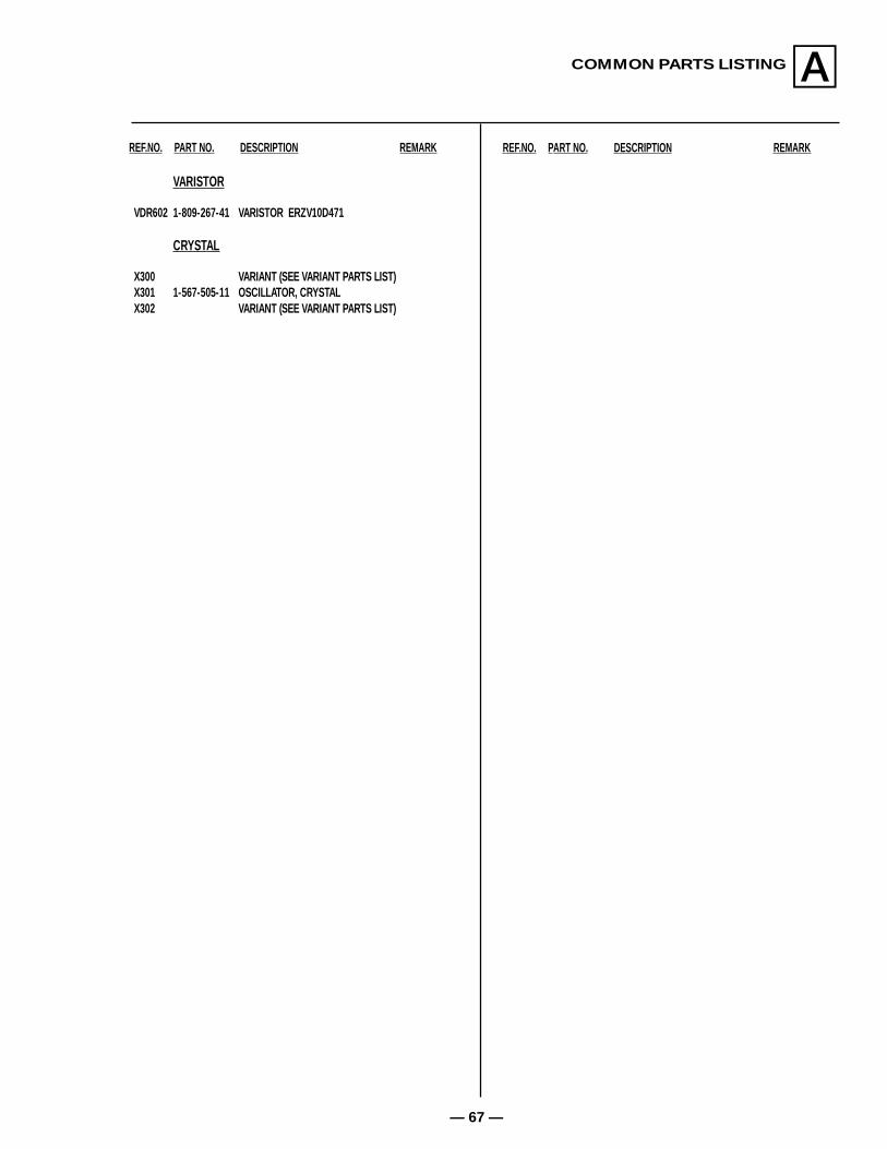
VARISTOR
VDR602 1-809-267-41 VARISTOR ERZV10D471
CRYSTAL
X300 VARIANT (SEE VARIANT PARTS LIST)X301 1-567-505-11 OSCILLATOR, CRYSTALX302 VARIANT (SEE VARIANT PARTS LIST)
The parts on this page belong to the following model(s) only:
REF.NO. PART NO. DESCRIPTION REMARK REF.NO. PART NO. DESCRIPTION REMARK


![[ba] Validity date from [BA] COUNTRY [ba] United States ...](https://static.documents.pub/doc/80x56/6191cacde75d406c8e1bf890/ba-validity-date-from-ba-country-ba-united-states-.jpg)


