Page 1
IBAU HAMBURG
Marine Terminals, Ship Loaders and Unloaders,
Cement Tanker, Equipment for Power Plants,
Special Applications
Information
I BAU HAMBURG
0504
I BAU HAMBURG · Rödingsmarkt 35 · D-20459 Hamburg · PHONE +49 (0) 40 36 13 090FAX +49 (0) 40 36 39 83 · Email: [email protected] · Internet: www.ibauhamburg.de
Self-DischargingCement Carrier
Along a river in Germany, mobile unloading
Saudi Arabia, mobile unloading Bamberg, Germany, stationary unloading
Page 2
Cement Carriers
2 3
Information
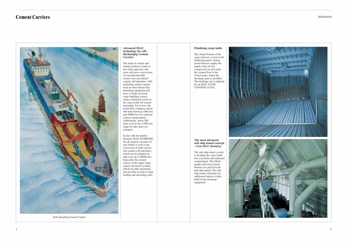
Fluidizing cargo holds
The sloped bottom of the
cargo hold are covered with
fluidizing panels. Rotary
piston blowers supply the
panels with oil-free
compressed air and make
the cement flow to the
lowest point, where the
discharge gate is installed.
The discharge rate is adjusted
by an IBAU FLOW
CONTROL GATE.
The most advanced mid ship tunnel concept– from IBAU Hamburg
The mid ship tunnel system
is dividing the cargo holds
into a portside and starboard
compartment. The IBAU
pumps and rotary piston
blowers are placed in the
mid ship tunnel. The mid
ship tunnel eliminates an
additional bottom to deck
hold for the discharge
equipment.
Advanced IBAU technology for self- discharging CementCarriers
The trade of cement and
similar products results in
new ship capacities and
more and more conversions
of conventional bulk
carriers into specialised
cement self-unloaders. Self-
unloading cement carriers
need no shore based ship
unloading equipment and
have a totally enclosed
cargo handling system,
using a fluidized system in
the cargo holds for cement
unloading. Up to now, the
world fleet comprises about
300 units between 1000 dwt
and 60000 dwt for seaborne
cement transportation.
Additionally, about 200
units exist in the <1000 dwt
range for lake and river
transport.
In line with the market
demand, IBAU HAMBURG
has developed concepts for
new builds as well as the
conversion of bulk carriers
into cement self-unloaders,
which can be adapted for
ship sizes up to 60000 dwt.
Especially the cement
carriers in the upper range
require advanced systems,
which are fully automated
and possible to achieve high
loading and unloading rates.
Self-unloading Cement Carrier
Page 3
Cement Carriers
4 5
Information
IBAU HAMBURG newself-discharging technology
Advanced self-unloaders in
the 1000 dwt to 60000 dwt
range are equipped with
fluidisation systems in the
cargo holds. The systems can
be installed in new builds
and conversions within three
month. They can be adapted
to the different ship sizes and
different types of cement, fly
ash or similar materials.
Unique in the IBAU concept
is the space saving mid ship
tunnel design that integrates
the discharge equipment and
divides the holds into a
portside and starboard
compartment. The mid ship
tunnel eliminates an
additional bottom to deck
hold for the discharge
equipment.
The fluidisation system
comprises inclined aeration
panels, which cover the
complete hold bottom.
Cement flows to the lowest
points in the holds, where
IBAU flow control gates are
installed, which allow an
adjustable and computerised
flow. For transporting the
cement from the holds to the
shore terminal, special
designed screw pumps are
used, which have a very low
feed point and allow a lateral
feed from left and right hand
side. Each pump transports
up to 350 t/h cement.
Conveying distances of more
than 600 m can be achieved.
When different cement types
such as white and grey
cement have to be
transported one after another
with the same cement tanker
a 100% cement reclaim from
the cargo holds is required.
The innovative IBAU
vacuum cleaner assists the
reclaiming process, to make
a 100% cement reclaiming
rate possible. The cargo
holds are equipped with
docking stations for the
mechanical cleaner, which
directs the remaining cement
between aeration panels into
the bin of an IBAU pump.
Particle separation is
effected in the pump filter
and no additional cement
transportation equipment is
needed.
How it works:Cement Carrierloading/unloading
The self-unloader is loaded
and unloaded in the most
flexible and simple way by
mean of IBAU pumps. To
achieve unloading rates of
up to 1200 t/h, four IBAU
pumps can be used in paral-
lel. The pumps are supplied
with oil-free conveying air
by screw compressors,
which are located in deck
houses, together with the
filtering equipment. For
direct loading with high
capacities again IBAU screw
pumps are used, which
pneumatically convey the
cement through one or more
pipelines directly into the
cargo holds.
Flexible hoses for the
connection of the shore and
ship pipes are carried by an
on-board crane. Loading
lines on deck are equipped
with motor actuated IBAU
two way valves for directing
the cement into the selected
holds. The required com-
pressed air is generated by
the compressors on board.
For cement distribution on
deck from a central
receiving bin either fluid
slides or horizontal screws
can be used. IBAU
fluid slides are used for
capacities up to 1200 t/h,
while IBAU screw
conveyors are recommended
for capacities up to 500 t/h.
Such systems are very
common if a mechanical
ship loader is used.
For highest reliability,
cement loading and
reclaiming for the self-
unloader can be completely
automated and computer
controlled. During loading,
cement is automatically
directed into the holds, while
the ship is balanced.
Unloading rates can be pre
selected and the operator
gets information about any
hold and discharge
equipment at any time.
IBAU HAMBURG can fit
the computer systems with
latest state-of-the-art tech-
nology to ensure highest
possible through the hold
capacity with the shortest
lay time for the ship in port.
The described loading /
unloading technology
optimal assists computer
automation.
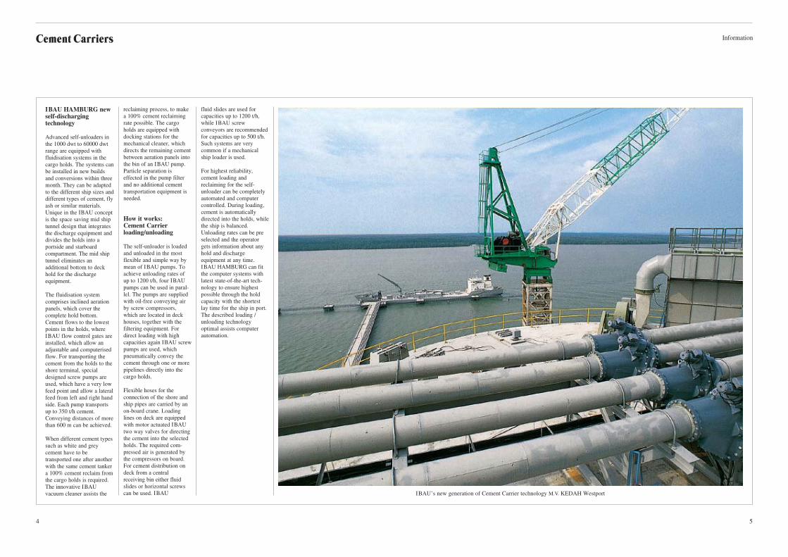
IBAU’s new generation of Cement Carrier technology M.V. KEDAH Westport
Page 4
InformationCement Carriers
6 7
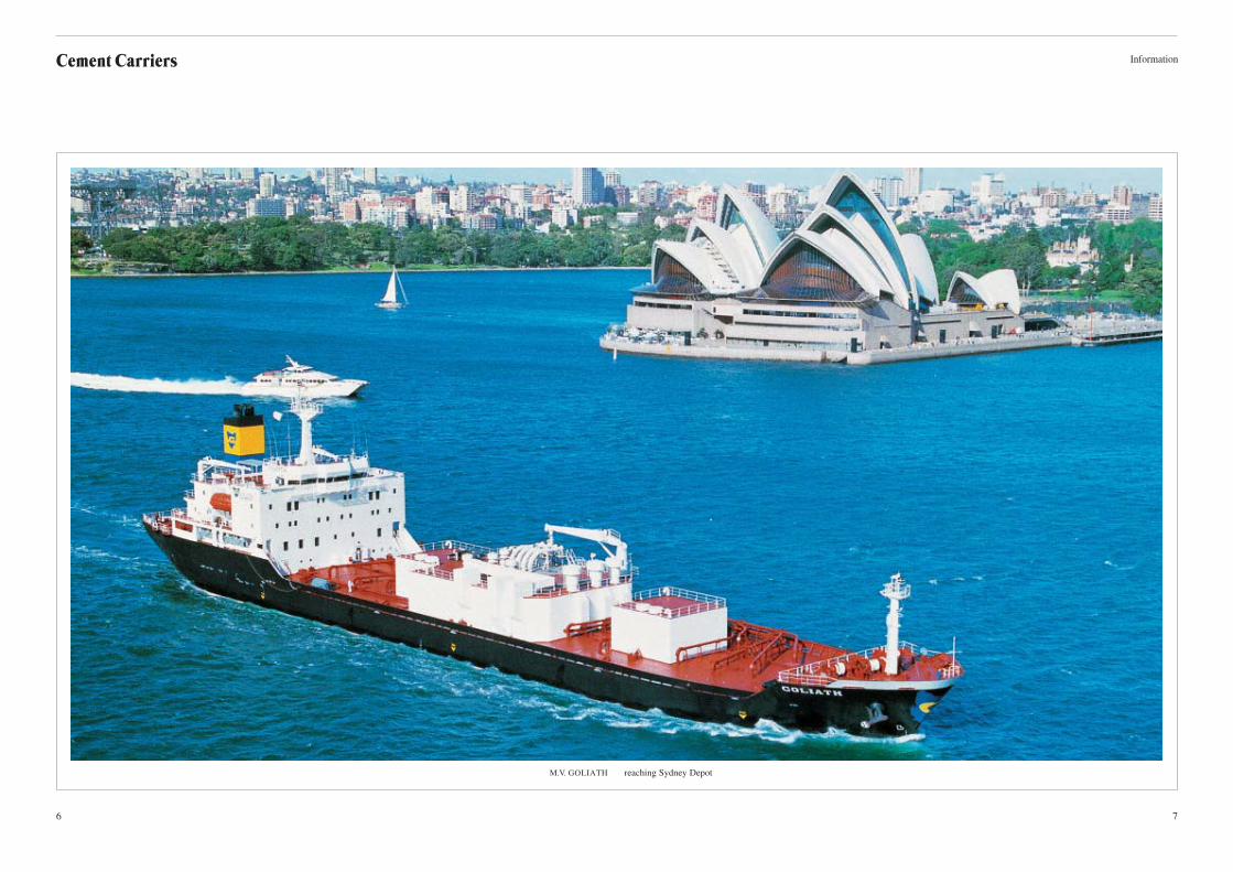
M.V. GOLIATH reaching Sydney Depot
Page 5
Cement Carriers
8 9
Information
M.V. GOLIATH Devonport Harbour supply depot The drawing shows the general layout of the cement tanker M.V. GOLIATH (15,000 dwt)
1 Crane for carrying the flexible loading and unloading lines
2 Loading lines on deck
3 Deckshouses with 4 filters and exhaust fans
4 Deckshouse with 8 compressors
5 Four cargoholds divided by midships tunnel into star and portside compartment
6 Four I BAU pumps and 8 rotary blowers placed in the midships tunnel
13
2
6
4
5
UPPER DECK
HOLD PLAN
Page 6
InformationCement Carriers
10 11
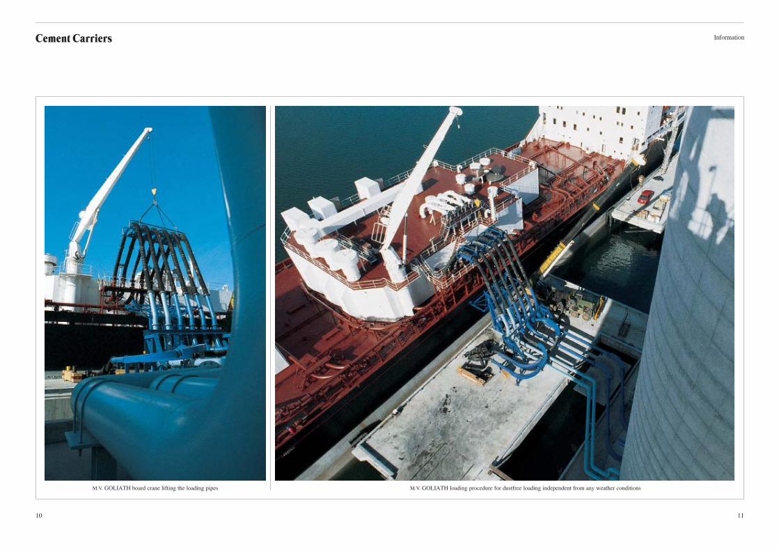
M.V. GOLIATH board crane lifting the loading pipes M.V. GOLIATH loading procedure for dustfree loading independent from any weather conditions
Page 7
13
InformationCement Carriers
12
M.V. KORALIA reaching one supply depot
M.V. KORALIA cement carrier
The drawing shows the general layout of the cement tanker M.V. KORALIA (8,500 dwt)
1 Crane for carrying the flexible loading and unloading lines
2 Loading lines on deck
3 Deckshouses with filters and exhaust fans
4 Deckshouses with compressors
5 Four cargoholds divided by a midships tunnel into star and portside compartment
6 Four IBAU pumps and rotary piston blowers placed in the midships tunnel
1
3
2
4
5
6
UPPER DECK
HOLD PLAN
Page 8
15
InformationCement Carriers
14
M.V. KEDAH I
Cement supply
on the open sea
M.V. KEDAH II
in the dry dock
M.V. KEDAH III
during one of
the supply voyage
The drawing shows the general layout of the cement tanker M.V. KEDAH I, I I & III (16,000 dwt)
1 Loading fluidslides
2 Deckshouses with filters and exhaust fans
3 Deckshouses with compressors
4 Four cargoholds divided by a midships tunnel into star and portside compartment
5 Four IBAU pumps and rotary piston blowers placed in the midships tunnel
1
2
3
4
5
UPPER DECK
HOLD PLAN
Page 9
17
InformationCement Carriers
16
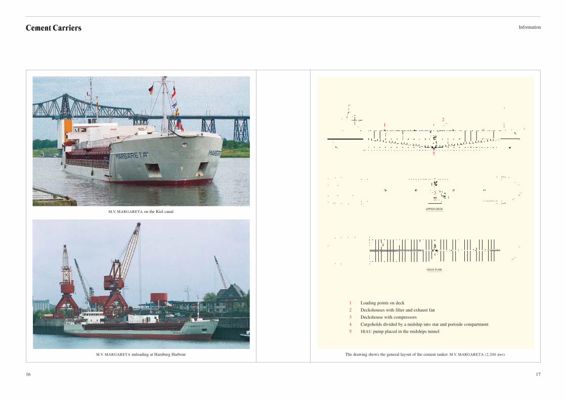
M.V. MARGARETA unloading at Hamburg Harbour
M.V. MARGARETA on the Kiel canal
The drawing shows the general layout of the cement tanker M.V. MARGARETA (2,200 dwt)
1 Loading points on deck
2 Deckshouses with filter and exhaust fan
3 Deckshouse with compressors
4 Cargoholds divided by a midship into star and portside compartment
5 IBAU pump placed in the midships tunnel
1
2
5
3
4
UPPER DECK
HOLD PLAN
Page 10
Cement Carriers
18 19
Information
M.V. CEMSEA terminal at Rostock harbour The drawing shows the general layout of the cement tanker M.V. CEMSEA (4,100 dwt)
1 Loading points on deck
2 Deckshouse with compressors
3 Cargoholds divided by a midship into star and portside compartment
4 Horizontel scrw conveyer placed in the midship tunnel
5 IBAU pump placed in the midships tunnel
1 2
5
3
4
UPPER DECK
HOLD PLAN
Page 11
InformationCement Carriers
20 21
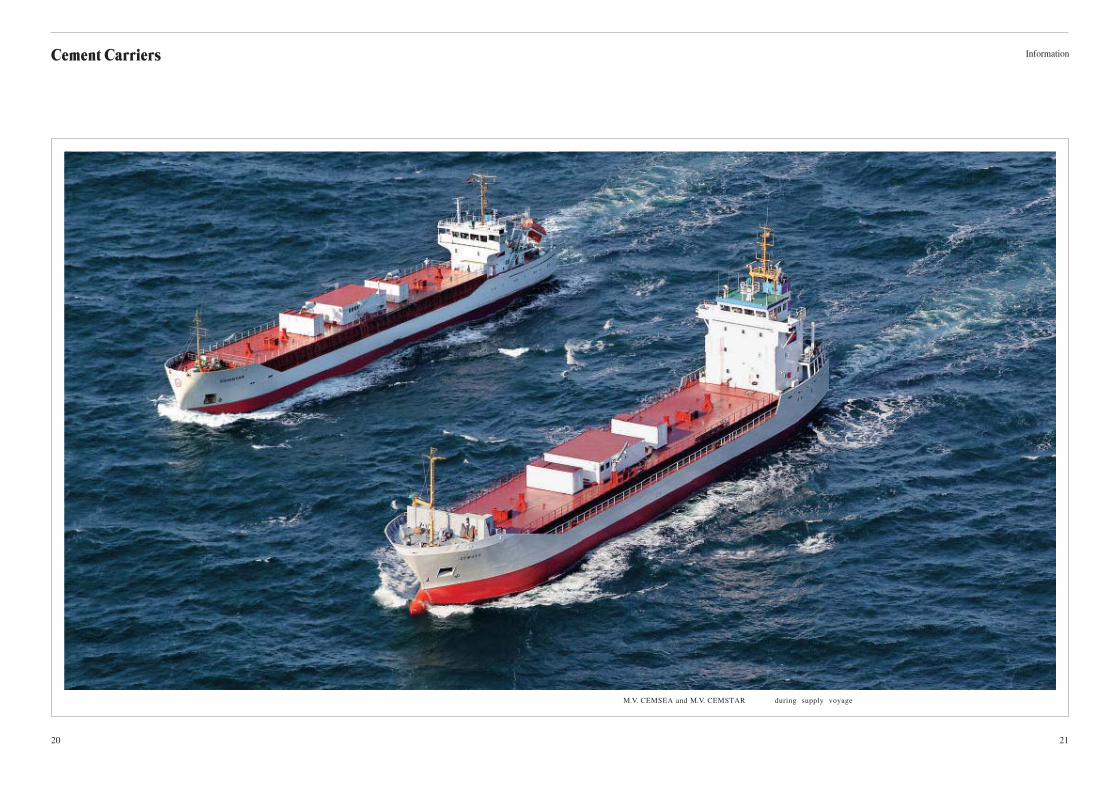
M.V. CEMSEA and M.V. CEMSTAR during supply voyage
Page 12
23
InformationCement Carriers
22
Preparation for discharge
M.V. CEMSEA at the Kiel channel
M.V. CEMSEA cement supply by HOLCIM
Page 13
25
InformationCement Carriers
24
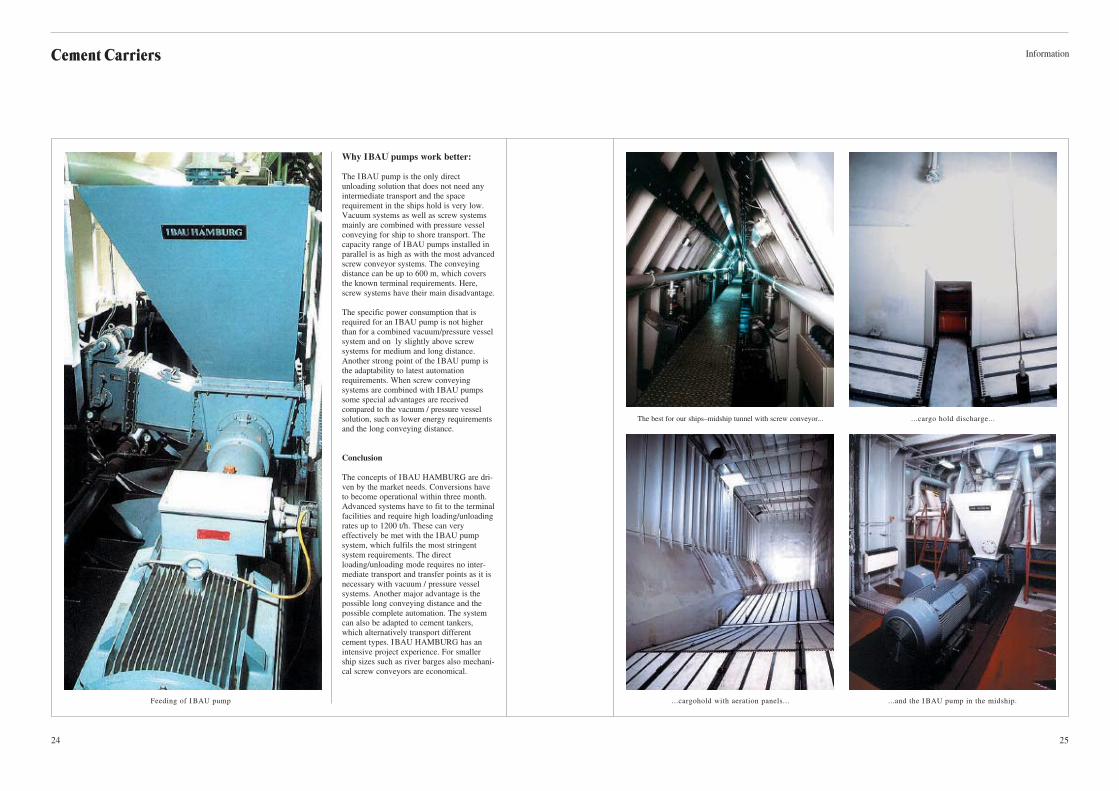
The best for our ships–midship tunnel with screw conveyor... ...cargo hold discharge...
...and the I BAU pump in the midship....cargohold with aeration panels...Feeding of I BAU pump
Why IBAU pumps work better:
The IBAU pump is the only direct
unloading solution that does not need any
intermediate transport and the space
requirement in the ships hold is very low.
Vacuum systems as well as screw systems
mainly are combined with pressure vessel
conveying for ship to shore transport. The
capacity range of IBAU pumps installed in
parallel is as high as with the most advanced
screw conveyor systems. The conveying
distance can be up to 600 m, which covers
the known terminal requirements. Here,
screw systems have their main disadvantage.
The specific power consumption that is
required for an IBAU pump is not higher
than for a combined vacuum/pressure vessel
system and on ly slightly above screw
systems for medium and long distance.
Another strong point of the IBAU pump is
the adaptability to latest automation
requirements. When screw conveying
systems are combined with IBAU pumps
some special advantages are received
compared to the vacuum / pressure vessel
solution, such as lower energy requirements
and the long conveying distance.
Conclusion
The concepts of IBAU HAMBURG are dri-
ven by the market needs. Conversions have
to become operational within three month.
Advanced systems have to fit to the terminal
facilities and require high loading/unloading
rates up to 1200 t/h. These can very
effectively be met with the IBAU pump
system, which fulfils the most stringent
system requirements. The direct
loading/unloading mode requires no inter-
mediate transport and transfer points as it is
necessary with vacuum / pressure vessel
systems. Another major advantage is the
possible long conveying distance and the
possible complete automation. The system
can also be adapted to cement tankers,
which alternatively transport different
cement types. IBAU HAMBURG has an
intensive project experience. For smaller
ship sizes such as river barges also mechani-
cal screw conveyors are economical.
Page 14
27
InformationCement Carriers
26
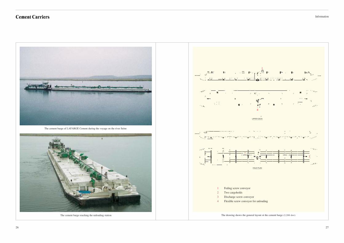
The cement barge reaching the unloading station The drawing shows the general layout ot the cement barge (2,200 dwt)
The cement barge of LAFARGE Cement during the voyage on the river Seine
1 Feding screw conveyor
2 Two cargoholds
3 Discharge screw conveyor
4 Flexible screw conveyor for unloading
1
4
2
3
UPPER DECK
HOLD PLAN
Page 15
InformationCement Carriers
28 29
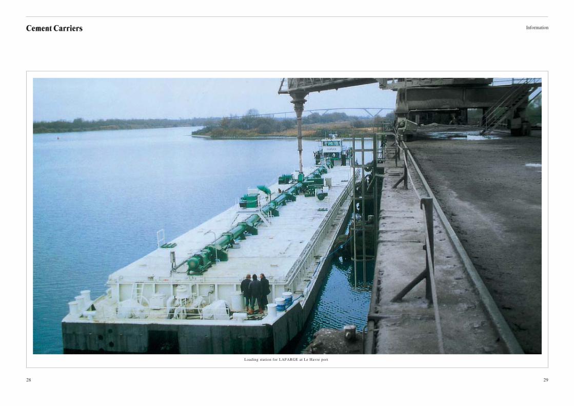
Loading station for LAFARGE at Le Havre port
Page 16
Cement Carriers
30 31
Information
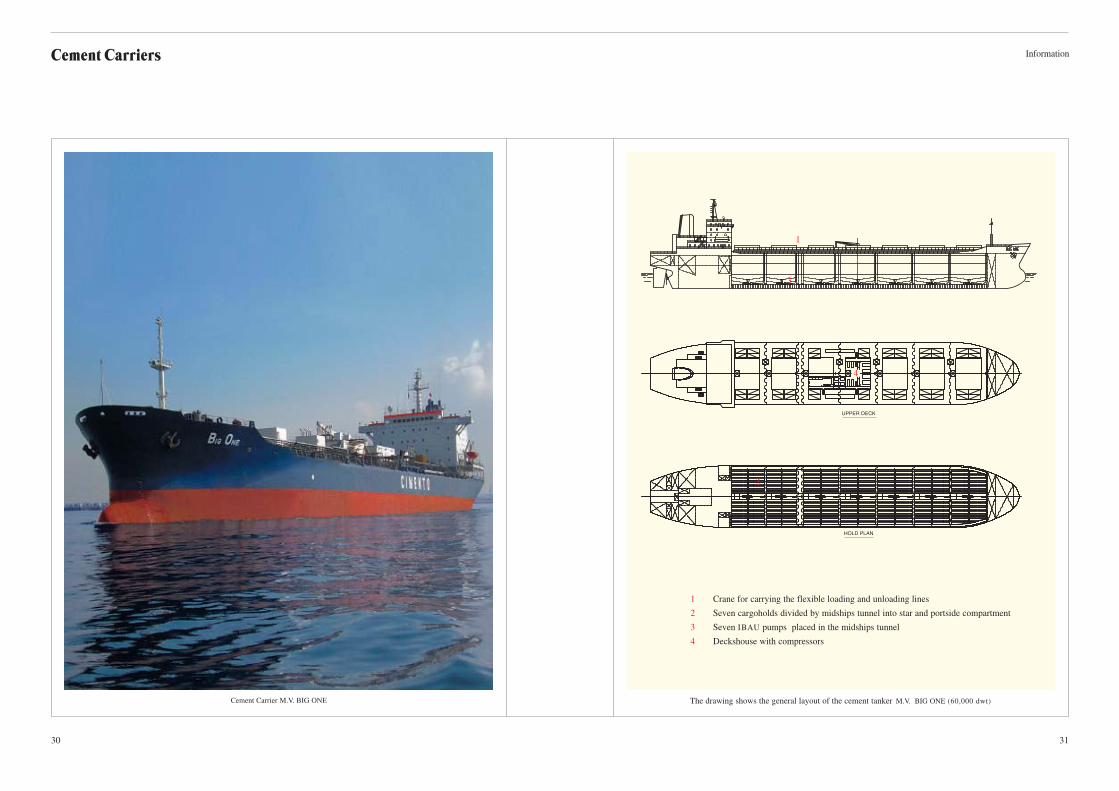
Cement Carrier M.V. BIG ONE The drawing shows the general layout of the cement tanker M.V. BIG ONE (60,000 dwt)
1 Crane for carrying the flexible loading and unloading lines
2 Seven cargoholds divided by midships tunnel into star and portside compartment
3 Seven IBAU pumps placed in the midships tunnel
4 Deckshouse with compressors
1
2
3
4
UPPER DECK
HOLD PLAN