3
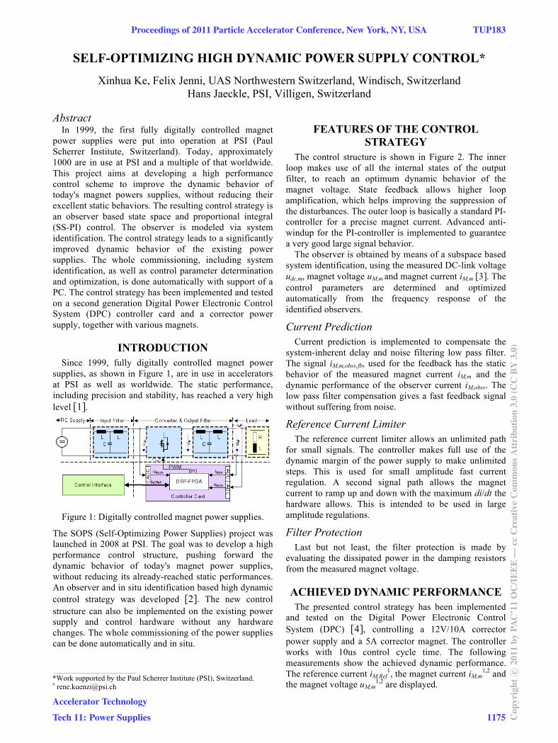
SELF-OPTIMIZING HIGH DYNAMIC POWER SUPPLY CONTROL* Xinhua Ke, Felix Jenni, UAS Northwestern Switzerland, Windisch, Switzerland Hans Jaeckle, PSI, Villigen, Switzerland Abstract In 1999, the first fully digitally controlled magnet power supplies were put into operation at PSI (Paul Scherrer Institute, Switzerland). Today, approximately 1000 are in use at PSI and a multiple of that worldwide. This project aims at developing a high performance control scheme to improve the dynamic behavior of today's magnet powers supplies, without reducing their excellent static behaviors. The resulting control strategy is an observer based state space and proportional integral (SS-PI) control. The observer is modeled via system identification. The control strategy leads to a significantly improved dynamic behavior of the existing power supplies. The whole commissioning, including system identification, as well as control parameter determination and optimization, is done automatically with support of a PC. The control strategy has been implemented and tested on a second generation Digital Power Electronic Control System (DPC) controller card and a corrector power supply, together with various magnets. INTRODUCTION Since 1999, fully digitally controlled magnet power supplies, as shown in Figure 1, are in use in accelerators at PSI as well as worldwide. The static performance, including precision and stability, has reached a very high level [1]. Figure 1: Digitally controlled magnet power supplies. The SOPS (Self-Optimizing Power Supplies) project was launched in 2008 at PSI. The goal was to develop a high performance control structure, pushing forward the dynamic behavior of today's magnet power supplies, without reducing its already-reached static performances. An observer and in situ identification based high dynamic control strategy was developed [2]. The new control structure can also be implemented on the existing power supply and control hardware without any hardware changes. The whole commissioning of the power supplies can be done automatically and in situ. FEATURES OF THE CONTROL STRATEGY The control structure is shown in Figure 2. The inner loop makes use of all the internal states of the output filter, to reach an optimum dynamic behavior of the magnet voltage. State feedback allows higher loop amplification, which helps improving the suppression of the disturbances. The outer loop is basically a standard PI- controller for a precise magnet current. Advanced anti- windup for the PI-controller is implemented to guarantee a very good large signal behavior. The observer is obtained by means of a subspace based system identification, using the measured DC-link voltage u dc,m , magnet voltage u M,m and magnet current i M,m [3]. The control parameters are determined and optimized automatically from the frequency response of the identified observers. Current Prediction Current prediction is implemented to compensate the system-inherent delay and noise filtering low pass filter. The signal i M,m,obsv,fb , used for the feedback has the static behavior of the measured magnet current i M,m and the dynamic performance of the observer current i M,obsv . The low pass filter compensation gives a fast feedback signal without suffering from noise. Reference Current Limiter The reference current limiter allows an unlimited path for small signals. The controller makes full use of the dynamic margin of the power supply to make unlimited steps. This is used for small amplitude fast current regulation. A second signal path allows the magnet current to ramp up and down with the maximum di/dt the hardware allows. This is intended to be used in large amplitude regulations. Filter Protection Last but not least, the filter protection is made by evaluating the dissipated power in the damping resistors from the measured magnet voltage. ACHIEVED DYNAMIC PERFORMANCE The presented control strategy has been implemented and tested on the Digital Power Electronic Control System (DPC) [4], controlling a 12V/10A corrector power supply and a 5A corrector magnet. The controller works with 10us control cycle time. The following measurements show the achieved dynamic performance. The reference current i M,Ref 1 , the magnet current i M,m 1,2 and the magnet voltage u M,m 1,2 are displayed. ____________________________________________ *Work supported by the Paul Scherrer Institute (PSI), Switzerland. # [email protected] Proceedings of 2011 Particle Accelerator Conference, New York, NY, USA TUP183 Accelerator Technology Tech 11: Power Supplies 1175 Copyright c ○ 2011 by PAC’11 OC/IEEE — cc Creative Commons Attribution 3.0 (CC BY 3.0)