Krishna K. Dey1, Ubaldo Cordova-Figueroa3, Thomas E. Mallouk1* and Ayusman Sen1*
Non-mechanical nano- and microscale pumps that function without the aid of an external power source and provideprecise control over the flow rate in response to specific signals are needed for the development of new autonomous nano-and microscale systems. Here we show that surface-immobilized enzymes that are independent of adenosine triphosphatefunction as self-powered micropumps in the presence of their respective substrates. In the four cases studied (catalase,lipase, urease and glucose oxidase), the flow is driven by a gradient in fluid density generated by the enzymatic reaction.The pumping velocity increases with increasing substrate concentration and reaction rate. These rechargeable pumps canbe triggered by the presence of specific analytes, which enables the design of enzyme-based devices that act both assensor and pump. Finally, we show proof-of-concept enzyme-powered devices that autonomously deliver small moleculesand proteins in response to specific chemical stimuli, including the release of insulin in response to glucose.
Self-powered nano- and micropumps that precisely control flowrate in response to external stimuli are critical to the design ofthe next generation of smart devices. Ideally, the pump should
enable fluid flow to be controlled both by the presence and concen-tration of the specific analyte, such as a substrate, promoter (cofac-tor) or a related biomarker. This coupling between sensing andtransport should allow new applications such as the bottom-upassembly of dynamic structures, cargo delivery at specific locations(for example, drug delivery) and related functions1,2.
Recently, autonomous motion that arises from the catalytic har-nessing of chemical free energy from the surrounding environmenthas been demonstrated at the nano- and microscale1–10. Tetheringthese catalytic systems to surfaces enables the transfer of the mech-anical force to the surrounding fluid. Utilizing this, a variety ofpumps have been designed and fabricated that operate on the micro-scale and function as delivery vehicles for fluids, small moleculesand colloids11–28. A major drawback of these artificial micropumpsis their non-biocompatibility with respect to the catalyst, fuel oreven the ionic-strength regime in which they operate. Biocatalysts,such as enzymes, provide an obvious solution to this problem.
The diffusive mobility of single enzyme molecules has beenshown to increase in the presence of a substrate in a concentration-dependent manner and, when exposed to a substrate concentrationgradient, ensembles of enzyme molecules exhibit chemotaxis29–31.Enzymes that move by generating a continuous surface force in afluid should, when fixed in place, function as micropumps thatmove fluid and colloidal particles in a directed manner. Here wedescribe a novel enzyme-based platform that combines sensingand microfluidic pumping into a single self-powered microdevice.These micropumps are substrate specific and their pumping speedcan be tuned by altering the substrate concentration. In addition,the pumps can be triggered by different analytes that, in situ,generate the substrate for the respective enzymes. This approachdemonstrates that even adenosine triphosphate (ATP)-independentenzymes can generate movement and can be used as micropumps inthe presence of the appropriate fuel (substrate). Finally, we showthat an enzyme-immobilized hydrogel can be used as a scaffoldfor micropumps that actively pump out gel-entrapped small
molecules and proteins (for example, insulin) in response to aspecific chemical trigger (for example, glucose). This opens up thepossibility of designing novel stimuli-responsive autonomouscargo and drug-delivery systems32.
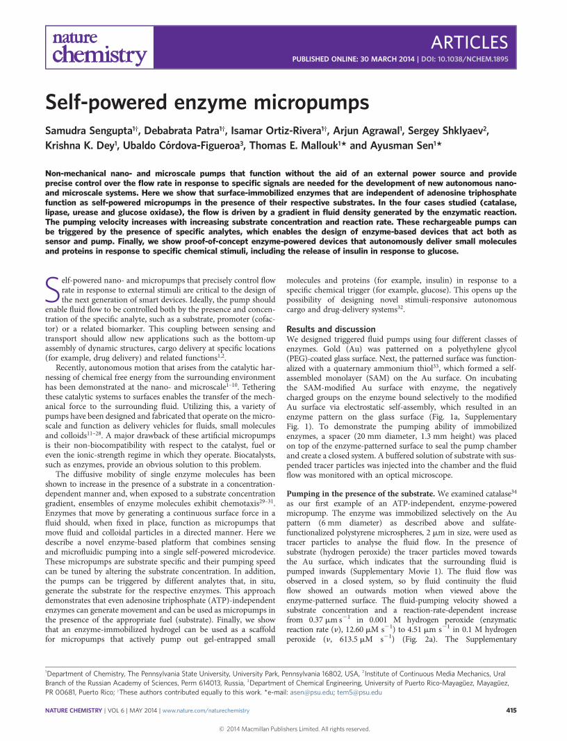
Results and discussionWe designed triggered fluid pumps using four different classes ofenzymes. Gold (Au) was patterned on a polyethylene glycol(PEG)-coated glass surface. Next, the patterned surface was function-alized with a quaternary ammonium thiol33, which formed a self-assembled monolayer (SAM) on the Au surface. On incubatingthe SAM-modified Au surface with enzyme, the negativelycharged groups on the enzyme bound selectively to the modifiedAu surface via electrostatic self-assembly, which resulted in anenzyme pattern on the glass surface (Fig. 1a, SupplementaryFig. 1). To demonstrate the pumping ability of immobilizedenzymes, a spacer (20 mm diameter, 1.3 mm height) was placedon top of the enzyme-patterned surface to seal the pump chamberand create a closed system. A buffered solution of substrate with sus-pended tracer particles was injected into the chamber and the fluidflow was monitored with an optical microscope.
Pumping in the presence of the substrate. We examined catalase34
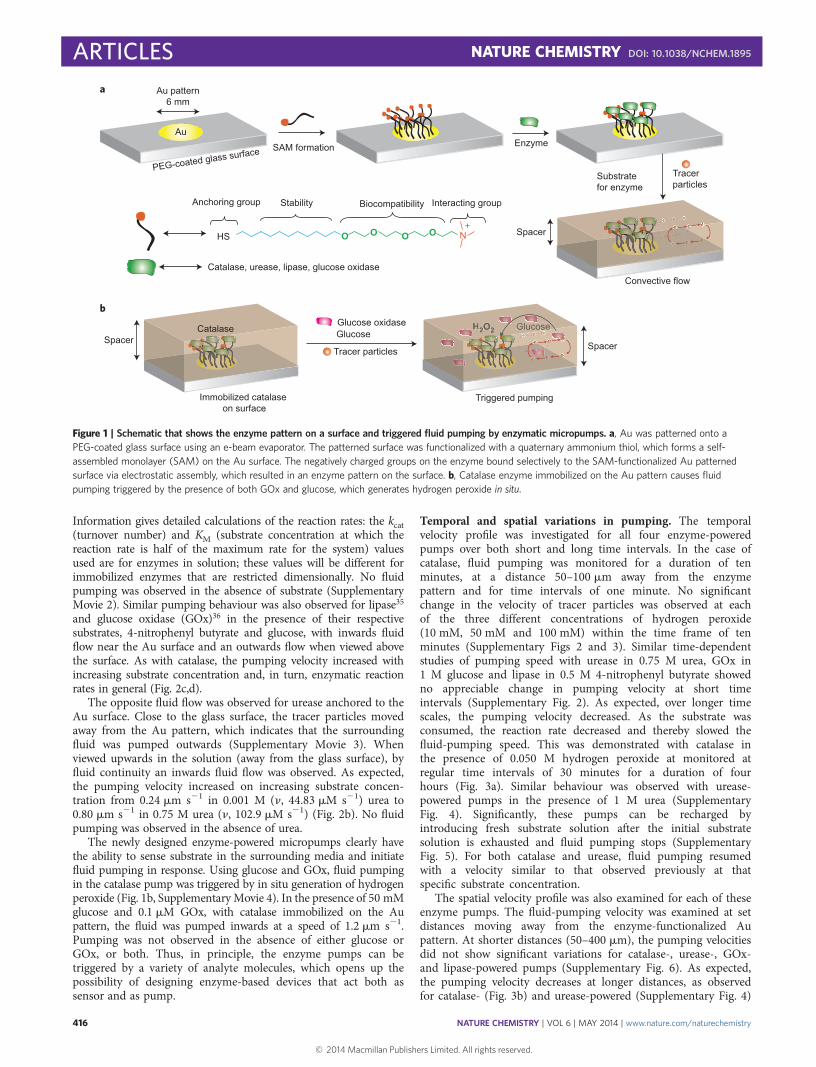
as our first example of an ATP-independent, enzyme-poweredmicropump. The enzyme was immobilized selectively on the Aupattern (6 mm diameter) as described above and sulfate-functionalized polystyrene microspheres, 2 mm in size, were used astracer particles to analyse the fluid flow. In the presence ofsubstrate (hydrogen peroxide) the tracer particles moved towardsthe Au surface, which indicates that the surrounding fluid ispumped inwards (Supplementary Movie 1). The fluid flow wasobserved in a closed system, so by fluid continuity the fluidflow showed an outwards motion when viewed above theenzyme-patterned surface. The fluid-pumping velocity showed asubstrate concentration and a reaction-rate-dependent increasefrom 0.37 mm s21 in 0.001 M hydrogen peroxide (enzymaticreaction rate (n), 12.60 mM s21) to 4.51 mm s21 in 0.1 M hydrogenperoxide (n, 613.5 mM s21) (Fig. 2a). The Supplementary
1Department of Chemistry, The Pennsylvania State University, University Park, Pennsylvania 16802, USA, 2Institute of Continuous Media Mechanics, UralBranch of the Russian Academy of Sciences, Perm 614013, Russia, 3Department of Chemical Engineering, University of Puerto Rico-Mayaguez, Mayaguez,PR 00681, Puerto Rico; †These authors contributed equally to this work. *e-mail: [email protected]; [email protected]
ARTICLESPUBLISHED ONLINE: 30 MARCH 2014 | DOI: 10.1038/NCHEM.1895
Information gives detailed calculations of the reaction rates: the kcat(turnover number) and KM (substrate concentration at which thereaction rate is half of the maximum rate for the system) valuesused are for enzymes in solution; these values will be different forimmobilized enzymes that are restricted dimensionally. No fluidpumping was observed in the absence of substrate (SupplementaryMovie 2). Similar pumping behaviour was also observed for lipase35
and glucose oxidase (GOx)36 in the presence of their respectivesubstrates, 4-nitrophenyl butyrate and glucose, with inwards fluidflow near the Au surface and an outwards flow when viewed abovethe surface. As with catalase, the pumping velocity increased withincreasing substrate concentration and, in turn, enzymatic reactionrates in general (Fig. 2c,d).
The opposite fluid flow was observed for urease anchored to theAu surface. Close to the glass surface, the tracer particles movedaway from the Au pattern, which indicates that the surroundingfluid was pumped outwards (Supplementary Movie 3). Whenviewed upwards in the solution (away from the glass surface), byfluid continuity an inwards fluid flow was observed. As expected,the pumping velocity increased on increasing substrate concen-tration from 0.24 mm s21 in 0.001 M (n, 44.83 mM s21) urea to0.80 mm s21 in 0.75 M urea (n, 102.9 mM s21) (Fig. 2b). No fluidpumping was observed in the absence of urea.
The newly designed enzyme-powered micropumps clearly havethe ability to sense substrate in the surrounding media and initiatefluid pumping in response. Using glucose and GOx, fluid pumpingin the catalase pump was triggered by in situ generation of hydrogenperoxide (Fig. 1b, Supplementary Movie 4). In the presence of 50 mMglucose and 0.1 mM GOx, with catalase immobilized on the Aupattern, the fluid was pumped inwards at a speed of 1.2 mm s21.Pumping was not observed in the absence of either glucose orGOx, or both. Thus, in principle, the enzyme pumps can betriggered by a variety of analyte molecules, which opens up thepossibility of designing enzyme-based devices that act both assensor and as pump.
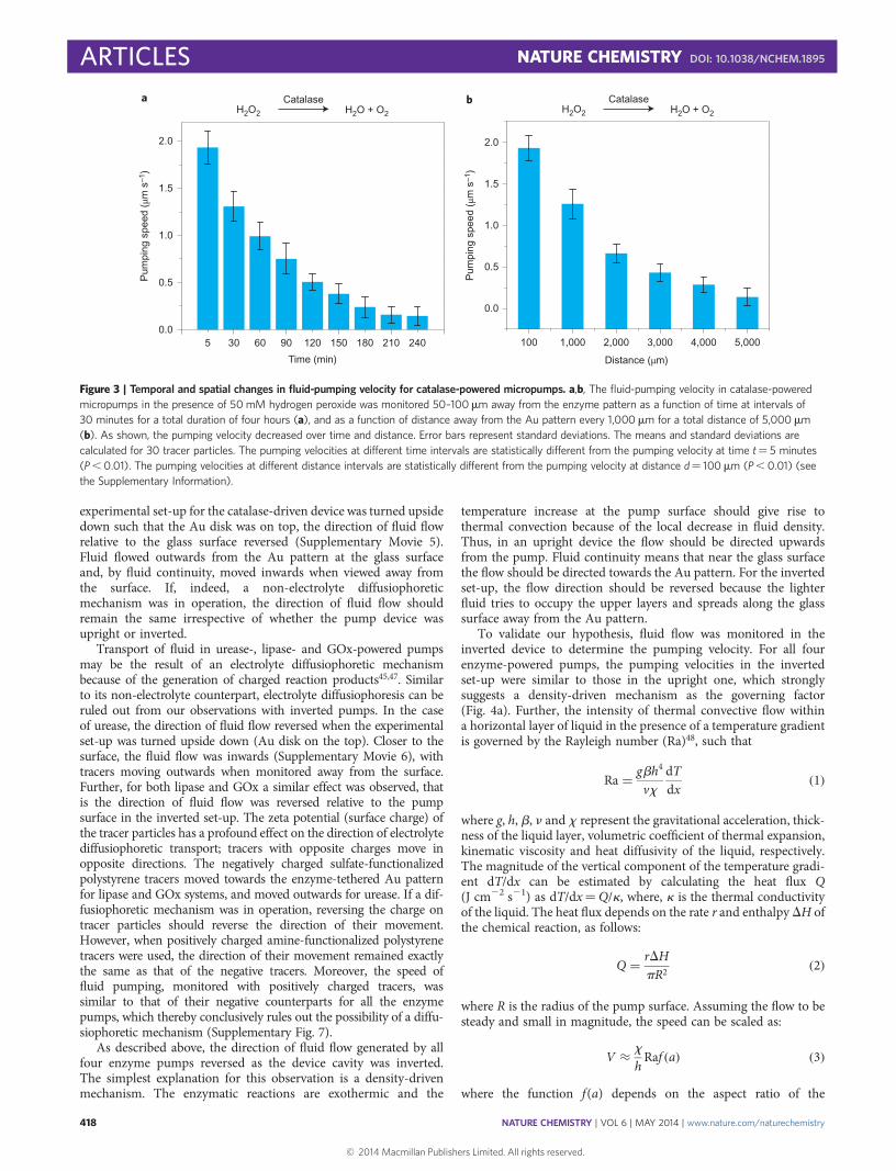
Temporal and spatial variations in pumping. The temporalvelocity profile was investigated for all four enzyme-poweredpumps over both short and long time intervals. In the case ofcatalase, fluid pumping was monitored for a duration of tenminutes, at a distance 50–100 mm away from the enzymepattern and for time intervals of one minute. No significantchange in the velocity of tracer particles was observed at eachof the three different concentrations of hydrogen peroxide(10 mM, 50 mM and 100 mM) within the time frame of tenminutes (Supplementary Figs 2 and 3). Similar time-dependentstudies of pumping speed with urease in 0.75 M urea, GOx in1 M glucose and lipase in 0.5 M 4-nitrophenyl butyrate showedno appreciable change in pumping velocity at short timeintervals (Supplementary Fig. 2). As expected, over longer timescales, the pumping velocity decreased. As the substrate wasconsumed, the reaction rate decreased and thereby slowed thefluid-pumping speed. This was demonstrated with catalase inthe presence of 0.050 M hydrogen peroxide at monitored atregular time intervals of 30 minutes for a duration of fourhours (Fig. 3a). Similar behaviour was observed with urease-powered pumps in the presence of 1 M urea (SupplementaryFig. 4). Significantly, these pumps can be recharged byintroducing fresh substrate solution after the initial substratesolution is exhausted and fluid pumping stops (SupplementaryFig. 5). For both catalase and urease, fluid pumping resumedwith a velocity similar to that observed previously at thatspecific substrate concentration.
The spatial velocity profile was also examined for each of theseenzyme pumps. The fluid-pumping velocity was examined at setdistances moving away from the enzyme-functionalized Aupattern. At shorter distances (50–400 mm), the pumping velocitiesdid not show significant variations for catalase-, urease-, GOx-and lipase-powered pumps (Supplementary Fig. 6). As expected,the pumping velocity decreases at longer distances, as observedfor catalase- (Fig. 3b) and urease-powered (Supplementary Fig. 4)
SAM formation EnzymeAu
Au pattern6 mm
PEG-coated glass surface
Substratefor enzyme
Tracer particles
HS O O O NO+
Stability Biocompatibility Interacting groupAnchoring group
Catalase, urease, lipase, glucose oxidase
Convective flow
Immobilized catalase on surface
Glucose oxidase GlucoseGlucose
H2O2
Triggered pumping
Catalase
a
b
Spacer
SpacerTracer particles
GlucoseH2O2 e
Spacer
Figure 1 | Schematic that shows the enzyme pattern on a surface and triggered fluid pumping by enzymatic micropumps. a, Au was patterned onto a
PEG-coated glass surface using an e-beam evaporator. The patterned surface was functionalized with a quaternary ammonium thiol, which forms a self-
assembled monolayer (SAM) on the Au surface. The negatively charged groups on the enzyme bound selectively to the SAM-functionalized Au patterned
surface via electrostatic assembly, which resulted in an enzyme pattern on the surface. b, Catalase enzyme immobilized on the Au pattern causes fluid
pumping triggered by the presence of both GOx and glucose, which generates hydrogen peroxide in situ.
ARTICLES NATURE CHEMISTRY DOI: 10.1038/NCHEM.1895
NATURE CHEMISTRY | VOL 6 | MAY 2014 | www.nature.com/naturechemistry416
pumps monitored at distance intervals of 1,000 mm, for an overalldistance of 5,000 mm.
Pumping mechanism. Figure 2 suggests that pumping velocity isgenerally proportional to the reaction rate, which in turn iscontrolled by both substrate concentration and inherent catalyticactivity. A detailed understanding of the mechanism will allow usto a priori predict the limits of reactive sensing and detection forspecific analyte–pump combinations. It is possible to rule outseveral alternative mechanisms. Pumping that arises from phoreticmechanisms37,38, such as diffusiophoresis39, osmophoresis40 and
self-electrophoresis41, has been demonstrated in the past forsurface-anchored catalytic particles18–24,27. Symmetry breaking byanchoring catalysts to solid surfaces can lead to chemicalgradients because of the asymmetric production or depletion ofsolute molecules (charged or uncharged)38,42–44. Directionalmovement of tracers in the catalase-powered pump can arise froma non-electrolyte diffusiophoretic mechanism because of agradient caused by the conversion of hydrogen peroxide (tworeactant molecules) into water and oxygen (three productmolecules)45,46. However, such a mechanism can be ruled outfrom our observations with an inverted pump set-up. When the
12.60 115.0 414.0 613.5
Reaction rate (μM s–1)
0
1
2
3
4
5
0.001 0.010 0.050 0.100
[Hydrogen peroxide] (M)P
umpi
ng s
peed
(μm
s–1
)
44.83 91.25 101.8 102.6 102.8 102.90.0
0.2
0.4
0.6
0.8
1.00.001 0.010 0.100 0.250 0.500 0.750
[Urea] (M)
0.0
0.1
0.2
0.3
0.4
0.5
0.6
0.70.001 0.010 0.100 0.500
[4-nitrophenyl butyrate] (M)
0.02937 0.2276 0.7004 0.88410.0
0.2
0.4
0.6
0.8
1.00.001 0.010 0.100 1.000
[Glucose] (M)
Pum
ping
spe
ed (μm
s–1
)P
umpi
ng s
peed
(μm
s–1
)
Pum
ping
spe
ed (μm
s–1
)
Reaction rate (μM s–1)
Reaction rate (μM s–1) Reaction rate (μM s–1)
ba
dc
0.01706 0.02311 0.02400 0.02404
H2O2
CatalaseH2O + O2
Glucoseoxidase
Gluconic acid + H2O2β-D-glucose + O2NO2
OO O OH
NO2
HOLipase
+
(NH2)2COUrease
NH4+ + HCO3
–
Figure 2 | Fluid pumping velocity in an enzyme-powered micropump as a function of substrate concentration and reaction rate. a, Pumping velocity in a
catalase-powered micropump increases in the presence of its substrate in a reaction-rate-dependent fashion, at substrate concentrations that ranged from
0.001 M to 0.1 M hydrogen peroxide. b, Pumping velocity in a urease-powered micropump increases on increasing the substrate concentration from 0.001 M
to 0.75 M urea. c, Pumping velocity in a lipase-powered micropump shows a concentration-dependent increase at substrate concentrations from 0.001 M to
0.5 M 4-nitrophenyl butyrate. d, Pumping velocity in a GOx-powered micropump increases in a substrate concentration- and reaction-rate-dependent manner
from 0.001 M to 1 M glucose. The reaction-rate calculations are based on kcat and KM values for enzymes in solution. Error bars represent standard
deviations. The means and standard deviations are calculated for 30 tracer particles. The pumping velocities at different substrate concentrations are
statistically different (P , 0.01) (see the Supplementary Information).
experimental set-up for the catalase-driven device was turned upsidedown such that the Au disk was on top, the direction of fluid flowrelative to the glass surface reversed (Supplementary Movie 5).Fluid flowed outwards from the Au pattern at the glass surfaceand, by fluid continuity, moved inwards when viewed away fromthe surface. If, indeed, a non-electrolyte diffusiophoreticmechanism was in operation, the direction of fluid flow shouldremain the same irrespective of whether the pump device wasupright or inverted.
Transport of fluid in urease-, lipase- and GOx-powered pumpsmay be the result of an electrolyte diffusiophoretic mechanismbecause of the generation of charged reaction products45,47. Similarto its non-electrolyte counterpart, electrolyte diffusiophoresis can beruled out from our observations with inverted pumps. In the caseof urease, the direction of fluid flow reversed when the experimentalset-up was turned upside down (Au disk on the top). Closer to thesurface, the fluid flow was inwards (Supplementary Movie 6), withtracers moving outwards when monitored away from the surface.Further, for both lipase and GOx a similar effect was observed, thatis the direction of fluid flow was reversed relative to the pumpsurface in the inverted set-up. The zeta potential (surface charge) ofthe tracer particles has a profound effect on the direction of electrolytediffusiophoretic transport; tracers with opposite charges move inopposite directions. The negatively charged sulfate-functionalizedpolystyrene tracers moved towards the enzyme-tethered Au patternfor lipase and GOx systems, and moved outwards for urease. If a dif-fusiophoretic mechanism was in operation, reversing the charge ontracer particles should reverse the direction of their movement.However, when positively charged amine-functionalized polystyrenetracers were used, the direction of their movement remained exactlythe same as that of the negative tracers. Moreover, the speed offluid pumping, monitored with positively charged tracers, wassimilar to that of their negative counterparts for all the enzymepumps, which thereby conclusively rules out the possibility of a diffu-siophoretic mechanism (Supplementary Fig. 7).
As described above, the direction of fluid flow generated by allfour enzyme pumps reversed as the device cavity was inverted.The simplest explanation for this observation is a density-drivenmechanism. The enzymatic reactions are exothermic and the
temperature increase at the pump surface should give rise tothermal convection because of the local decrease in fluid density.Thus, in an upright device the flow should be directed upwardsfrom the pump. Fluid continuity means that near the glass surfacethe flow should be directed towards the Au pattern. For the invertedset-up, the flow direction should be reversed because the lighterfluid tries to occupy the upper layers and spreads along the glasssurface away from the Au pattern.
To validate our hypothesis, fluid flow was monitored in theinverted device to determine the pumping velocity. For all fourenzyme-powered pumps, the pumping velocities in the invertedset-up were similar to those in the upright one, which stronglysuggests a density-driven mechanism as the governing factor(Fig. 4a). Further, the intensity of thermal convective flow withina horizontal layer of liquid in the presence of a temperature gradientis governed by the Rayleigh number (Ra)48, such that
Ra = gbh4
vxdTdx
(1)
where g, h, b, n and x represent the gravitational acceleration, thick-ness of the liquid layer, volumetric coefficient of thermal expansion,kinematic viscosity and heat diffusivity of the liquid, respectively.The magnitude of the vertical component of the temperature gradi-ent dT/dx can be estimated by calculating the heat flux Q(J cm22 s21) as dT/dx¼Q/k, where, k is the thermal conductivityof the liquid. The heat flux depends on the rate r and enthalpy DH ofthe chemical reaction, as follows:
Q = rDHpR2
(2)
where R is the radius of the pump surface. Assuming the flow to besteady and small in magnitude, the speed can be scaled as:
V ≈ x
hRaf (a) (3)
where the function f(a) depends on the aspect ratio of the
0.0
0.5
1.0
1.5
2.0
100 1,000 2,000 3,000 4,000 5,000
Distance (µm)
Pum
ping
spe
ed (µm
s–1
)
b
0.0
0.5
1.0
1.5
2.0
Pum
ping
spe
ed (µm
s–1
)
5 60 120 180 240
a
30 90 150 210
Time (min)
H2O2
CatalaseH2O + O2 H2O2
CatalaseH2O + O2
Figure 3 | Temporal and spatial changes in fluid-pumping velocity for catalase-powered micropumps. a,b, The fluid-pumping velocity in catalase-powered
micropumps in the presence of 50 mM hydrogen peroxide was monitored 50–100mm away from the enzyme pattern as a function of time at intervals of
30 minutes for a total duration of four hours (a), and as a function of distance away from the Au pattern every 1,000 mm for a total distance of 5,000 mm
(b). As shown, the pumping velocity decreased over time and distance. Error bars represent standard deviations. The means and standard deviations are
calculated for 30 tracer particles. The pumping velocities at different time intervals are statistically different from the pumping velocity at time t¼ 5 minutes
(P , 0.01). The pumping velocities at different distance intervals are statistically different from the pumping velocity at distance d¼ 100 mm (P , 0.01) (see
the Supplementary Information).
ARTICLES NATURE CHEMISTRY DOI: 10.1038/NCHEM.1895
NATURE CHEMISTRY | VOL 6 | MAY 2014 | www.nature.com/naturechemistry418
micropump, a¼ R/h. The flow, therefore, can be characterized by aspeed given by:
V � gbh3rDHnkpR2
f a( ) (4)
At small Ra the function f(a) can be found by solving twouncoupled boundary-value problems: first, to derive the tempera-ture of the fluid by solving the Laplace equation with the pre-scribed heat flux at the reactive patch and constant temperatureat the upper plate; second, the fluid velocity can be found viathe linearized Navier–Stokes–Boussinesq equation. To reiterate,within this linear model, f(a) only changes its sign when thegravity is inverted.
Numerical calculations within this approach showed thatf(a) grows from zero up to a value of 1023, with saturatingbeyond R . 3h. Therefore, for R . 3h, any increase in the layerthickness h should result in an increase in the flow speed pro-portional to h3. For smaller a, the prefactor f(a) slightly diminishesthis effect. For example, for the experimental set-up with a¼ 2.3(R¼ 3 mm, h¼ 1.3 mm), the velocity grows by a factor of 6.6when the layer thickness is doubled. For three different enzymes,the speed increased approximately by a factor of 6.8, which confirmsour theoretical proposition (Fig. 4b). Further, assuming thatthe values of the reaction rate (r¼ 1027 mol s21), enthalpy(DH¼ 100 kJ mol21) and height of the cavity (h¼ 1 mm) are ofthe same order of magnitude for all the enzymes, the speed wasdetermined as �1 mm s21, in good agreement with the experimen-tal results. Interestingly, even though Ra for our system is fairly high(�10), the smaller magnitude of f(a) helps in keeping the flow speedlinear in Ra.
In the case of urease, the observed effect is opposite to the expectedone. Although the enzyme catalytic reaction is exothermic, the fluid ispumped outwards in the upright device. We hypothesized that asthe products of urea hydrolysis are all ionic (NH4
þ and HCO32),
these solvated ions can increase the density of the fluid near theenzyme pattern. This local increase in density causes the fluid tospread along the glass surface, which results in a density-driven con-vective flow that directs the fluid away from the pattern. In theinverted set-up, the denser fluid generated on the top of the devicesettles down to lower layers in the cavity, and by fluid continuity
drives the fluid flow inwards near the glass surface. Therefore, inthis case the fluid density can be written as:
r = r0(1 − b(T − T0) + bC(C − C0)) (5)
where r is the final fluid density, T is the absolute temperature, C isthe concentration of reaction products, r0, T0 and C0 are the referencevalues of these three characteristics, and bC is the solute’s coefficientof expansion. For bC . 0 the fluid density grows as the concentrationof products increases. Therefore, for urease the situation is more com-plicated and double-diffusive convection sets against the competingimpacts of the reaction on the flow density and hence on the flow.To verify our hypothesis, the fluid flow was examined in twodifferent systems.
The movement of tracer particles was monitored for the ureasepump in a vertical device set-up (Supplementary Fig. 8). The fluidflowed downwards when viewed both below and above theenzyme-patterned surface, which indicates an overall downwardsflow at the enzyme-patterned surface in the vertical set-up(Supplementary Movie 7). Again, by fluid continuity the fluidflowed upwards away from the surface. The reaction-generated pro-ducts, being denser than the reactants, settled to the bottom layers ofthe device and thereby drove the fluid-flow downwards. The mech-anism proposed for the urease-powered micropump can also beestablished by monitoring the fluid flow using a sink-reservoirmodel (see Supplementary Information).
Similar experiments that used vertical set-ups were performed withcatalase- and lipase-powered micropumps (Supplementary Fig. 8).In both of these cases, the fluid flow was upwards when viewedbelow the Au pattern close to the surface, against gravity(Supplementary Movie 8). This upwards fluid movement also sup-ports the mechanism proposed previously: convective flows resultfrom a thermal gradient. The increase in temperature at the pumpsurface caused by these enzyme catalytic reactions decreases thelocal fluid density for catalase and lipase, and thereby drives thefluid flows upwards. The effect of temperature on solute–particle inter-action may also play a role in the observed pumping49.
Substrate-triggered release of molecules. The ability of enzyme-powered micropumps to respond to an external stimulus (forexample, substrate) and produce a change in the surrounding
Catalase Lipase Urease GOx0
1
2
3
4 Upright pump set-up
Inverted pump set-up
100 mM hydrogen peroxide
100 mM PNB500 mM urea
10 mM β-D-glucose
Pum
ping
spe
ed (μm
s–1
)
Catalase Lipase Urease0
1
2
3
4
5
6
Single spacer (h)
Double spacer (2h)
Pum
ping
spe
ed (μm
s–1
)
10 mMhydrogen peroxide
100 mM PNB10 mM urea
ba
Figure 4 | Fluid pumping in enzyme micropumps generated by density-driven flows. a, The fluid-pumping velocity monitored in the upright and inverted
pump set-ups showed no significant difference for any of the four enzyme micropumps. Error bars represent standard deviations. The means and standard
deviations are calculated for 30 tracer particles. The pumping velocities monitored in the upright and inverted pump set-ups are not statistically different
(P . 0.01). b, The fluid-pumping velocity monitored in the double-spacer (two × height of chamber, h) set-up showed an approximately seven-fold increase
as compared with the single-spacer (h) set-up for three enzyme micropumps. Error bars represent standard deviations. The means and standard deviations
are calculated for 30 tracer particles. The pumping velocities monitored in the single- and double-spacer set-ups are statistically different (P , 0.01) (see the
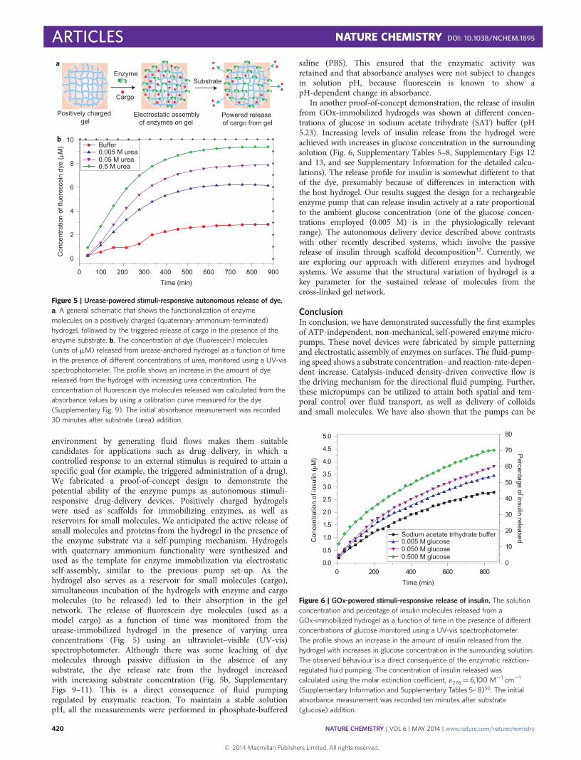
environment by generating fluid flows makes them suitablecandidates for applications such as drug delivery, in which acontrolled response to an external stimulus is required to attain aspecific goal (for example, the triggered administration of a drug).We fabricated a proof-of-concept design to demonstrate thepotential ability of the enzyme pumps as autonomous stimuli-responsive drug-delivery devices. Positively charged hydrogelswere used as scaffolds for immobilizing enzymes, as well asreservoirs for small molecules. We anticipated the active release ofsmall molecules and proteins from the hydrogel in the presence ofthe enzyme substrate via a self-pumping mechanism. Hydrogelswith quaternary ammonium functionality were synthesized andused as the template for enzyme immobilization via electrostaticself-assembly, similar to the previous pump set-up. As thehydrogel also serves as a reservoir for small molecules (cargo),simultaneous incubation of the hydrogels with enzyme and cargomolecules (to be released) led to their absorption in the gelnetwork. The release of fluorescein dye molecules (used as amodel cargo) as a function of time was monitored from theurease-immobilized hydrogel in the presence of varying ureaconcentrations (Fig. 5) using an ultraviolet–visible (UV-vis)spectrophotometer. Although there was some leaching of dyemolecules through passive diffusion in the absence of anysubstrate, the dye release rate from the hydrogel increasedwith increasing substrate concentration (Fig. 5b, SupplementaryFigs 9–11). This is a direct consequence of fluid pumpingregulated by enzymatic reaction. To maintain a stable solutionpH, all the measurements were performed in phosphate-buffered
saline (PBS). This ensured that the enzymatic activity wasretained and that absorbance analyses were not subject to changesin solution pH, because fluorescein is known to show apH-dependent change in absorbance.
In another proof-of-concept demonstration, the release of insulinfrom GOx-immobilized hydrogels was shown at different concen-trations of glucose in sodium acetate trihydrate (SAT) buffer (pH5.23). Increasing levels of insulin release from the hydrogel wereachieved with increases in glucose concentration in the surroundingsolution (Fig. 6, Supplementary Tables 5–8, Supplementary Figs 12and 13, and see Supplementary Information for the detailed calcu-lations). The release profile for insulin is somewhat different to thatof the dye, presumably because of differences in interaction withthe host hydrogel. Our results suggest the design for a rechargeableenzyme pump that can release insulin actively at a rate proportionalto the ambient glucose concentration (one of the glucose concen-trations employed (0.005 M) is in the physiologically relevantrange). The autonomous delivery device described above contrastswith other recently described systems, which involve the passiverelease of insulin through scaffold decomposition32. Currently, weare exploring our approach with different enzymes and hydrogelsystems. We assume that the structural variation of hydrogel is akey parameter for the sustained release of molecules from thecross-linked gel network.
ConclusionIn conclusion, we have demonstrated successfully the first examplesof ATP-independent, non-mechanical, self-powered enzyme micro-pumps. These novel devices were fabricated by simple patterningand electrostatic assembly of enzymes on surfaces. The fluid-pump-ing speed shows a substrate concentration- and reaction-rate-depen-dent increase. Catalysis-induced density-driven convective flow isthe driving mechanism for the directional fluid pumping. Further,these micropumps can be utilized to attain both spatial and tem-poral control over fluid transport, as well as delivery of colloidsand small molecules. We have also shown that the pumps can be
100 200 300 400 500 600 700 800 900
0
2
4
6
8
10
Time (min)
Con
cent
ratio
n of
fluo
resc
ein
dye
(μM
) Buffer 0.005 M urea0.05 M urea0.5 M urea
0
Enzyme
Cargo
Positively charged gel
Substrate
Electrostatic assembly of enzymes on gel
Powered release of cargo from gel
a
b
Figure 5 | Urease-powered stimuli-responsive autonomous release of dye.
a, A general schematic that shows the functionalization of enzyme
molecules on a positively charged (quaternary-ammonium-terminated)
hydrogel, followed by the triggered release of cargo in the presence of the
enzyme substrate. b, The concentration of dye (fluorescein) molecules
(units of mM) released from urease-anchored hydrogel as a function of time
in the presence of different concentrations of urea, monitored using a UV-vis
spectrophotometer. The profile shows an increase in the amount of dye
released from the hydrogel with increasing urea concentration. The
concentration of fluorescein dye molecules released was calculated from the
absorbance values by using a calibration curve measured for the dye
(Supplementary Fig. 9). The initial absorbance measurement was recorded
30 minutes after substrate (urea) addition.
0 200 400 600 8000.0
0.5
1.0
1.5
2.0
2.5
3.0
3.5
4.0
4.5
5.0
Sodium acetate trihydrate buffer 0.005 M glucose 0.050 M glucose 0.500 M glucose
Time (min)
Con
cent
ratio
n of
insu
lin (μM
)
0
10
20
30
40
50
60
70
80
Percentage of insulin released
Figure 6 | GOx-powered stimuli-responsive release of insulin. The solution
concentration and percentage of insulin molecules released from a
GOx-immobilized hydrogel as a function of time in the presence of different
concentrations of glucose monitored using a UV-vis spectrophotometer.
The profile shows an increase in the amount of insulin released from the
hydrogel with increases in glucose concentration in the surrounding solution.
The observed behaviour is a direct consequence of the enzymatic reaction-
regulated fluid pumping. The concentration of insulin released was
calculated using the molar extinction coefficient, 1276¼ 6,100 M21 cm21
(Supplementary Information and Supplementary Tables 5– 8)50. The initial
absorbance measurement was recorded ten minutes after substrate
(glucose) addition.
ARTICLES NATURE CHEMISTRY DOI: 10.1038/NCHEM.1895
NATURE CHEMISTRY | VOL 6 | MAY 2014 | www.nature.com/naturechemistry420
triggered by the presence of specific analytes. In principle, theanalyte can be a toxic substance that will be drawn towardsthe pump and be consumed as substrate, and thereby reduce itsambient concentration (for example, a phosphate-based nerveagent as a substrate for a phosphatase pump). Currently, work isin progress to pattern pumps that involve multienzyme cascadesto enable regulation and microfluidic logic. Finally, we describea proof-of-concept device that acts as a self-regulated, stimuli-responsive, active-delivery vehicle.
The ability of immobilized enzymes to pump fluids and particlesautonomously with velocities that are dictated by the concentrationof a specific analyte, either a second enzyme or a chemical, mayenable the development of smart micro- and nanoscale devicesthat contain sophisticated levels of control over the direction andvelocity of fluid and particle transport. From a technological stand-point, this work provides a novel intrinsic energy source for fluidmovement that will enhance microfluidic device design and over-come a critical barrier in the field in which pressure-drivenpumps are used to move fluids. Further, these self-poweredpumps can, in principle, remain viable and be capable of ‘turningon’ even after prolonged storage.
MethodsMicropump design, enzyme immobilization and particle tracking. An electronic-beam (e-beam) evaporator was used to produce the Au pattern on a PEG-coatedglass surface (MicroSurfaces). The e-beam evaporated a thickness of 90 nm of Au onthe PEG-functionalized surface, with a 10 nm adhesion layer of Cr. The radius of theAu pattern was 3 mm. The surface was cleaned thoroughly with isopropanolfollowed by acetone and dried by flowing nitrogen. Previously synthesizedquaternary ammonium thiol was used for SAM formation on the Au surface. Theligand was dissolved in methanol and the surface was incubated in this overnightat room temperature under an inert atmosphere. Later, the surface was washedseveral times with methanol followed by PBS buffer, and dried under an inertatmosphere. The SAM-modified surface was incubated in an enzyme solution for4–5 hours. The negatively charged enzymes bound selectively to the thiol-functionalized Au-patterned surface via electrostatic assembly. The enzyme-functionalized surface was thoroughly washed with PBS to remove any unboundenzyme molecules from the PEG-coated glass surface. The enzyme-patternedsurface was covered with a secure-seal hybridization chamber (Electron MicroscopySciences) with dimensions of 20 mm diameter and 1.3 mm height.
To monitor the fluid flow, in all our experiments functionalized polystyrenemicrospheres (Polysciences Inc.), 2 mm in size, were introduced as tracers suspendedin a buffered solution of substrate. Videos were captured using two differentoptical set-ups. One set-up comprised an upright optical microscope (OlympusBX60M) with a halogen lamp (12 V maximum, 100 W). Excitation light was focusedinto the sample through a 50× objective (LMPlanFLN 50× /0.5 BD 1/0/FN26.5,Olympus). Emission light was collected by the objective, passed through interferencefilters and finally detected by a high-sensitivity CCD (charge-coupled device)camera at 30 frames per second. Videos were recorded using this CCD cameraattached to the optical microscope. The other system also included an optical set-up,which comprised an inverted microscope (Zeiss Axiovert 200 MAT) with a halogenlamp (12 V maximum, 100 W). Excitation light was focused into the samplethrough a 20× objective (EC Epiplan-NEOFLUAR 50× /0.55 HD DIC 1/0, Zeiss)or 50× objective (LD EC Epiplan-NEOFLUAR 20× /0.5 HD DIC 422472-9960,Zeiss). Emission light was collected by the objective, passed through interferencefilters and finally detected by a high-sensitivity Flea 3 CCD camera (FL3-U3-32S2C-CS, Point Grey), which has a resolution of 2,080 × 1,552 pixels at 30 frames persecond. This camera was attached to the optical microscope and videos wererecorded. To measure fluid-pumping velocity in each experiment, 30 tracer particleswere tracked for a 25 second time interval using PhysVis software (Kenyon College).
Preparation of enzyme-functionalized hydrogels. For the preparation of enzyme-functionalized, dye-loaded hydrogels, small pieces of hydrogel (2 mm3) were cutand soaked overnight in a mixture of urease (2 mg ml21, 3 ml) and fluoresceindye (1 ml saturated) solution in PBS. The solution was kept in the refrigeratorovernight and allowed to come to room temperature before the experimentswere performed.
For the preparation of enzyme-functionalized, insulin-loaded hydrogels, smallpieces of hydrogel (2 mm3) were cut and soaked overnight in a mixture of GOx(2 mg ml21, 3 ml) and insulin (2 mg ml21, 3 ml) solution in SAT buffer (pH 5.23,adjusted with 0.1 M HCl). The solution was kept at 4 8C overnight, and broughtto room temperature before the experiments were performed.
Release of fluorescein dye from enzyme-functionalized hydrogels monitored withUV-vis spectroscopy. Hydrogel pieces were washed 3–4 times with fresh buffer (PBS
or SAT) to remove any excess enzyme and guest molecules. The gel pieces weretransferred to a UV-vis cell and buffer or substrate solution (urea or glucose) ofvarying concentrations was added to promote the release of the cargo. A BeckmanDU-800 Spectrophotometer with a six-cell sampler was used for the measurementsin kinetics and time mode, with the analytical wavelength set to 488 nm forfluorescein dye (maximum absorbance wavelength of fluorescein in PBS) and276 nm for insulin50 (maximum absorbance wavelength of insulin in SAT). Bothexperiments were carried out at 25 8C using 250 nm as the background wavelength.Measurements were set to be taken at periods of 30 or 60 minutes for a totalduration of �15 hours. Initial measurements were taken after 15–30 minutes for thedye-release experiment and after 10–15 minutes for the insulin release one. Dyerelease from the urease-immobilized hydrogels was analysed in 0 M, 0.005 M, 0.05 Mand 0.5 M urea solutions in PBS. Insulin release from GOx-immobilized hydrogelswas analysed in 0 M, 0.05 M, 0.25 M and 0.5 M glucose solutions in O2-saturatedSAT. Ultraviolet absorbance was plotted as a function of time at each of theseconcentrations, which gives a direct correlation between substrate concentrationand the amount of dye or insulin molecules released from the gel (SupplementaryTables 5–8, and Supplementary Fig. 9).
Syntheses. Detailed information on the synthesis of quaternary ammonium thiollinker, the selective attachment of enzyme molecules to the SAM-modified Au patternand the synthesis of hydrogel are provided in the Supplementary Information.
Received 8 August 2013; accepted 11 February 2014;published online 30 March 2014
References1. Sengupta, S., Ibele, M. E. & Sen, A. Fantastic voyage: designing self-powered
nanorobots. Angew. Chem. Int. Ed. 51, 8434–8445 (2012).2. Patra, D. et al. Intelligent, self-powered, drug delivery systems. Nanoscale
5, 1273–1283 (2013).3. Wang, J. Can man-made nanomachines compete with nature biomotors?
ACS Nano 3, 4–9 (2009).4. Sanchez, S. & Pumera, M. Nanorobots: the ultimate wireless self-propelled
sensing and actuating devices. Chem. Asian J. 4, 1402–1410 (2009).5. Hong, Y., Velegol, D., Chaturvedi, N. & Sen, A. Biomimetic behavior of synthetic
particles: from microscopic randomness to macroscopic control. Phys. Chem.Chem. Phys. 12, 1423–1425 (2010).
6. Mei, Y., Solovev, A. A., Sanchez, S. & Schmidt, O. G. Rolled-up nanotechon polymers: from basic perception to self-propelled catalytic microengines.Chem. Soc. Rev. 40, 2109–2119 (2011).
7. Mirkovic, T., Zacharia, N. S., Scholes, G. D. & Ozin, G. A. Nanolocomotion—catalytic nanomotors and nanorotors. Small 6, 159–167 (2010).
8. Paxton, W. F., Sen, A. & Mallouk, T. E. Motility of catalytic nanoparticlesthrough self-generated forces. Chem Eur. J. 11, 6462–6470 (2005).
9. Pumera, M. Nanomaterials meet microfluidics. Chem. Commun. 47,5671–5680 (2011).
10. Mallouk, T. E. & Sen, A. Powering nanorobots. Sci. Am. 300, 72–77 (2009).11. Laser, D. J. & Santiago, J. G. A review of micropumps. J. Micromech. Microeng.
14, R35–R64 (2004).12. Nisar, A., Afzulpurkar, N., Mahaisavariya, B. & Tuantranont, A. MEMS-based
micropumps in drug delivery and biomedical applications. Sens. Actuat. B Chem.130, 917–942 (2008).
13. Dash, A. K. & Cudworth II, G. C. Therapeutic applications of implantabledrug delivery systems. J. Pharmacol. Toxicol. Methods 40, 1–12 (1998).
14. Jakeway, S. C., de Mello, A. J. & Russell, E. L. Miniaturized total analysis systemsfor biological analysis. Fresenius J. Anal. Chem. 366, 525–539 (2000).
15. van der Schoot, B., Jeanneret, S., van den Berg, A. & de Rooij, F. A. A siliconintegrated miniature chemical analysis system. Sens. Actuat. B Chem.6, 57–60 (1992).
16. Khandurina, J. et al. Integrated system for rapid PCR-based DNA analysisin microfluidic devices. Anal. Chem. 72, 2995–3000 (2000).
17. Woolley, A. T. et al. Functional integration of PCR amplification andcapillary electrophoresis in a microfabricated DNA analysis device. Anal. Chem.68, 4081–4086 (1996).
18. Zhang, H. et al. Self-powered microscale pumps based on analyte-initiateddepolymerization reactions. Angew. Chem. Int. Ed. 51, 2400–2404 (2012).
19. Kline, T. R. et al. Catalytic micropumps: microscopic convective fluid flowand pattern formation. J. Am. Chem. Soc. 127, 17150–17151 (2005).
20. Ibele, M. E., Wang, Y., Kline, T. R., Mallouk, T. E. & Sen, A. Hydrazine fuelsfor bimetallic catalytic microfluidic pumping. J. Am. Chem. Soc. 129,7762–7763 (2007).
21. Jun, I. K. & Hess, H. A. A biomimetic, self-pumping membrane. Adv. Mater.22, 4823–4825 (2010).
22. Hong, Y., Diaz, M., Cordova-Figueroa, U. M. & Sen, A. Light-driven titanium-dioxide-based reversible microfireworks and micromotor/micropumpsystems. Adv. Funct. Mater. 20, 1568–1576 (2010).
23. Paxton, W. F. et al. Catalytically induced electrokinetics for motors andmicropumps. J. Am. Chem. Soc. 128, 14881–14888 (2006).
24. Solovev, A. A., Sanchez, S., Mei, Y. & Schmidt, O. G. Tunable catalytictubular micro-pumps operating at low concentrations of hydrogen peroxide.Phys. Chem. Chem. Phys. 13, 10131–10135 (2011).
25. Zhang, L. et al. Measurements and modeling of two-phase flow inmicrochannels with nearly constant heat flux boundary conditions.J. Microelectromech. Syst. 11, 12–19 (2002).
26. Hogg, T. & Freitas, R. A. Chemical power for microscopic robots incapillaries. Nanomedicine: Nanotech. Biol. Med. 6, 298–317 (2010).
27. Yadav, V., Zhang, H., Pavlick, R. A. & Sen, A. Triggered ‘on/off’ micropumpsand colloidal photodiode. J. Am. Chem. Soc. 134, 15688–15691 (2012).
28. Andersson, H., van der Wijngaart, W., Nilsson, P., Enoksson, P. & Stemme, G.A valve-less diffuser micropump for microfluidic analytical systems. Sens.Actuat. B Chem. 72, 259–265 (2001).
29. Sengupta, S. et al. Enzyme molecules as nanomotors. J. Am. Chem. Soc.135, 1406–1414 (2013).
30. Muddana, H. S., Sengupta, S., Mallouk, T. E., Sen, A. & Butler, P. J.Substrate catalysis enhances single-enzyme diffusion. J. Am. Chem. Soc.132, 2110–2111 (2010).
31. Yu, H., Jo, K., Kounovsky, K. L., de Pablo, J. J. & Schwartz, D. C. Molecularpropulsion: chemical sensing and chemotaxis of DNA driven by RNApolymerase. J. Am. Chem. Soc. 131, 5722–5723 (2009).
32. Gu, Z. et al. Glucose-responsive microgels integrated with enzyme nanocapsulesfor closed-loop insulin delivery. ACS Nano 7, 8, 6758–6766 (2013).
33. Miranda, O. R. et al. Enzyme-amplified array sensing of proteins in solutionand in biofluids. J. Am. Chem. Soc. 132, 5285–5289 (2010).
34. Gaetani, G. et al. Predominant role of catalase in the disposal of hydrogenperoxide within human erythrocytes. Blood 87, 1595–1599 (1996).
35. Svendsen, A. Lipase protein engineering. Biochim. Biophys. Acta 1543,223–228 (2000).
36. Raba, J. & Mottola, H. A. Glucose oxidase as an analytical reagent. Crit. Rev.Anal. Chem. 25, 1–42 (1995).
37. Golestanian, R., Liverpool, T. B. & Ajdari, A. Designing phoretic micro-and nano-swimmers. New J. Phys. 9, 126 (2007).
38. Golestanian, R., Liverpool, T. B. & Ajdari, A. Propulsion of a molecularmachine by asymmetric distribution of reaction products. Phys. Rev. Lett.94, 220801 (2005).
39. Anderson, J. L. & Prieve, D. C. Diffusiophoresis: migration of colloidalparticles in gradients of solute concentration. Separ. Purif. Method 13,67–103 (1984).
40. Pavlick, R. A., Sengupta, S., McFadden, T., Zhang, H. & Sen, A. Apolymerization-powered motor. Angew. Chem. Int. Ed. 50, 9374–9377 (2011).
41. Moran, J. L. & Posner, J. D. Electrokinetic locomotion by reaction inducedcharge auto-electrophoresis. J. Fluid Mech. 680, 31–66 (2011).
42. Howse, J. R. et al. Self-motile colloidal particles: from directed propulsionto random walk. Phys. Rev. Lett. 99, 048102 (2007).
43. Cordova-Figueroa, U. M. & Brady, J. F. Osmotic propulsion: the osmoticmotor. Phys. Rev. Lett. 100, 158303 (2008).
44. Ke, H., Ye, S., Carroll, R. L. & Showalter, K. Motion analysis of self-propelledPt2silica particles in hydrogen peroxide solutions. J. Phys. Chem. A 114,5462–5467 (2010).
45. Anderson, J. L. Colloid transport by interfacial forces. Ann. Rev. Fluid Mech.21, 61–99 (1989).
46. Anderson, J. L., Lowell, M. E. & Prieve, D. C. Motion of a particle generatedby chemical gradients. Part 1. Non-electrolytes. J. Fluid Mech. 117,107–121 (1982).
47. Prieve, D. C., Anderson, J. L., Ebel, J. L. & Lowell, M. E. Motion of a particlegenerated by chemical gradients. Part 2. Electrolytes. J. Fluid Mech. 148,247–269 (1984).
48. Strutt, J. W. On convection currents in a horizontal layer of fluid, when thehigher temperature is on the underside. Phil. Mag. 32, 529–546 (1916).
49. Zhao, G. & Pumera, M. Macroscopic self-propelled objects. Chem. Asian J.7, 1994–2002 (2012).
50. Gammeltoft, S. Receptor binding of biosynthetic human insulin on isolatedpig hepatocytes. Diabetes Care 4, 2, 235–237 (1981).
AcknowledgementsWe gratefully acknowledge financial support by the Penn State Materials Research Scienceand Engineering Centers under National Sciences Foundation (NSF) grant DMR-0820404and, in part, by the Defense Threat Reduction Agency (HDTRA1-13-1-0039). Thispublication was supported by the Pennsylvania State University Materials ResearchInstitute Nanofabrication Lab and the SNF Cooperative Agreement No. ECS-0335765. Thispublication is also based on work supported by Award No. RUP1-7078-PE-12 of the USCivilian Research & Development Foundation (CRDF Global) and by the NSF underCooperative Agreement No. OISE-9531011 (joint grant with the Ural Branch of theRussian Academy of Sciences). I.O-R. acknowledges a NSF Fellowship (DGE-1255832).
Author contributionsS.S., D.P., T.E.M. and A.S. designed the research. S.S., D.P., I.O-R. and A.A. performed theresearch. S.S., D.P. and I.O-R. contributed new reagents and analytical tools. S.S., I.O-R.,K.K.D., S.Sh., U.C-F., T.E.M. and A.S. analysed the data. S.S., D.P., I.O-R and A.S. wrotethe manuscript.
Additional informationSupplementary information is available in the online version of the paper. Reprints andpermissions information is available online at www.nature.com/reprints. Correspondence andrequests for materials should be addressed to T.E.M. and A.S.
Competing financial interestsThe authors declare no competing financial interests.
ARTICLES NATURE CHEMISTRY DOI: 10.1038/NCHEM.1895
NATURE CHEMISTRY | VOL 6 | MAY 2014 | www.nature.com/naturechemistry422