Engineering Insights 2006 Self-Testable, Self-Adaptable and Error-Resilient System Design – Tim Cheng Electrical and Computer Engineering coping with increasing variability and reliability concerns
Transcript
Engineering Insights 2006
Self-Testable, Self-Adaptable and Error-Resilient System Design –
Tim ChengElectrical and Computer Engineering
coping with increasing variability and reliability concerns
Engineering Insights 2006
• Decreasing design window• Less tolerance for design revisions
• Decreasing design window• Less tolerance for design revisions
• Exponentially more transistors• Increasing complexity in system
context
• Exponentially more transistors• Increasing complexity in system
context
Time-to-Money Heterogeneity
• Coupling cap• Signal integrity• Inductance• Leakage
•• Coupling capCoupling cap•• Signal integritySignal integrity•• InductanceInductance•• LeakageLeakage
• Greater diversity of on-chip elements: processors, SW, RF, memory, analog, high-speed bus
•• Greater diversity of onGreater diversity of on--chip chip elements: elements: processors, SW, RF, processors, SW, RF, memory, analog, highmemory, analog, high--speed busspeed bus
Drivers of SystemDrivers of System--onon--aa--Chip/SystemChip/System--inin--aa--Package Design & Test TechnologiesPackage Design & Test Technologies
Com
plex
ityNanoScale
Effects
Engineering Insights 2006
Challenges Facing the Next Decade in Integrated System Design
• Managing and exploiting design partitioning and trade-offs for heterogeneous systems – HW, SW, analog, RF, MEMS, optical, etc..
• Power and energy• Verification and test• Reliability and robustness • Implementation fabrics beyond silicon
Engineering Insights 2006
Increasing Failure Sources and Failure Rates
40
50
60
70
80
90
100
110
Tem
pera
ture
(C)
On-Die Temperature variations
SEU
random defects
parametric variations
soft errors
design errors
Engineering Insights 2006
Harder to Design Reliable System-Chips• First-silicon success rate has been dropping
– <30% for complex ASIC/[email protected]– Pre-silicon logic bugs have been increasing at 3X-4X/generation
for Intel’s processors
• Yield has been dropping for volume production– IBM’s 8-core Cell-Processor chips: ~10-20% yield
• “Better than worst-case” design resulting in failures w/o defects– Increase in variation of process parameters with scaling– Worst-case design getting way too conservative
• One-time-factory production testing will be too costly and insufficient for failure screening
Engineering Insights 2006
New Design and Test Paradigm: Reliable Systems With Unreliable Components
• Systems must be designed to cope with failures• Efficient silicon debug is a must
– Design for debugging would become necessary• Must have embedded self-test for error detection
– For both testing in manufacturing line and in-the-field– Both on-line and off-line testing
• Must be re-configurable and adaptable for error recovery– Using spares to replace defective parts– Using redundancy to mask errors– Using self-tuning to compensate variations
Engineering Insights 2006
Some of Our Research Results• Embedded Software-Based Self-Test for SoC
– Reuse of embedded processors and on-chip resources for self-test and diagnosis
• Test, Characterization and Diagnosis for High Speed Serial IO Interfaces
• Silicon Debug for Timing Failures• Formal Equivalence Checking between System
Specification and RTL Code
Engineering Insights 2006
Embedded-Software-Based Self-Test For Programmable Systems
Test and diagnosis are applications of a programmable SOC!!Test and diagnosis are applications of a programmable SOC!!
Reuse of on-chip programmable components for testProcessor/DSP/FPGA cores for on-chip test generation, measurement, response analysis and even diagnosis
Self-test a processor using its instruction set for high fault coverageUse the tested processor/DSP to test buses, interfaces and other components, including analog and mixed-signal components
Engineering Insights 2006 Embedded SW-Based Self-Testing for Programmable System Chips
performance; more robust to process, temperature and voltage variations…
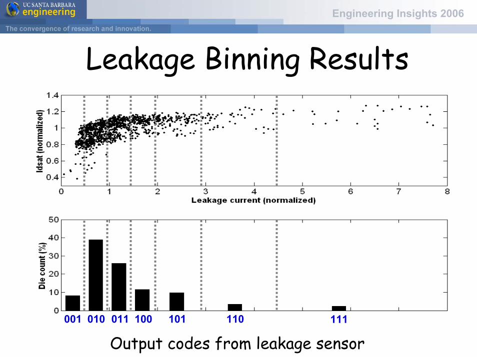
• Dynamic circuits– Using programmable keeper and on-chip leakage
sensors for tuning performance and robustness
Engineering Insights 2006
Dynamic Circuit Using Static Keeper
clk
. . .RS0 RS7
D0 D7
RS1
D1
LBL0
LBL1
N0
Keeper upsizing degrades average performance
Conventional Static Keeper
Engineering Insights 2006
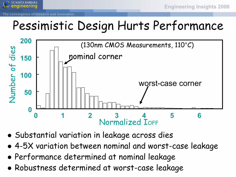
Pessimistic Design Hurts Performance
worst-case corner
(130nm CMOS Measurements, 110°C)
0
50
100
150
200
Normalized IOFF
Num
ber
of d
ies
0 1 2 3 4 5 6
nominal corner
Substantial variation in leakage across dies4-5X variation between nominal and worst-case leakagePerformance determined at nominal leakageRobustness determined at worst-case leakage
Engineering Insights 2006
Programmable Keeper for Dynamic Ckts3-bit programmable keeper
clk
. . .RS0 RS7
D0 D7
RS1
D1
LBL0
LBL1
N0
b[2:0]
W 2W 4Ws s s
Opportunistic speedup via keeper downsizingRef: C. Kim and K Roy, Purdue
Engineering Insights 2006
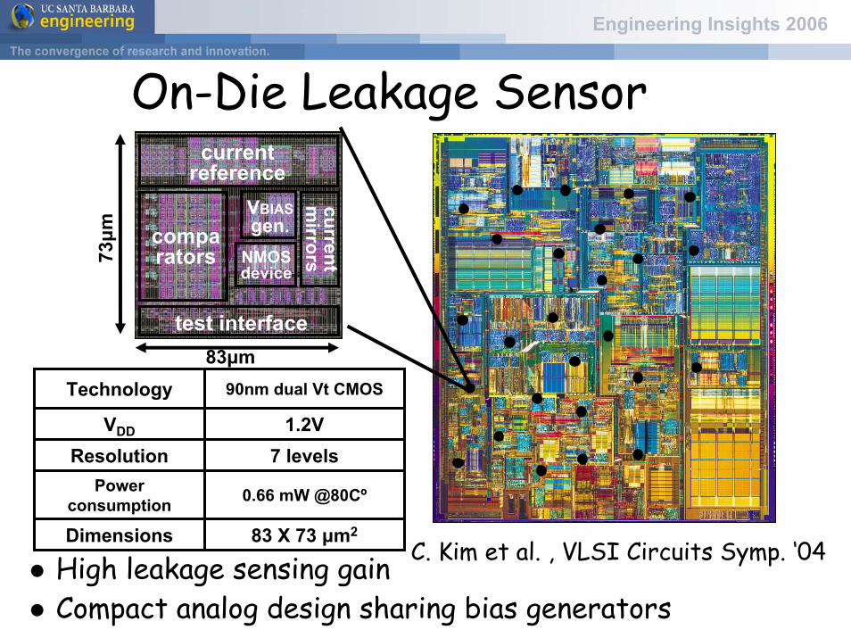
On-Die Leakage Sensor
C. Kim et al. , VLSI Circuits Symp. ‘04
83μm
73μm
current reference
comparators
currentm
irrors
VBIASgen.
NMOS device
test interface
High leakage sensing gain Compact analog design sharing bias generators
Digital Logic - Exploring Redundancy and Reconfiguration Tradeoffs
• Redundancy– Suitable for soft/transient/marginality errors– Different forms:
• Hardware redundancy • Time redundancy • Information redundancy
• Reconfiguration– Suitable for hard errors (e.g. defects)
• Design methodology and tools for area, power, performance and reliability tradeoffs?
Engineering Insights 2006
SummaryQuality can't be added, it has to be designed in. Cost-effective embedded self-test will replace existing manufacturing test methodologies for heterogeneous SoC/SiPPost-silicon tuning/calibration/reconfiguration is becoming promising, and necessary, for Si nano systems


![DS92LV242x 10-MHz to 75-MHz, 24-Bit Channel …2018-3-23 · DI[7:0] CI2 CI3 CLKIN PDB Serializer Deserializer CI1 Graphic Processor Channel Link II 1 Pair / AC Coupled DS92LV2421](https://static.documents.pub/doc/80x56/5b65c3a67f8b9a2a5c8c0251/ds92lv242x-10-mhz-to-75-mhz-24-bit-channel-2018-3-23di70-ci2-ci3-clkin.jpg)


