Self-Transfer Assistive Device for Hip and Knee Replacement Patients Bita Kasra, Lars Maxfield, Niklas Menke, Sina Tautz Advisor: Dr. Michael Sracic Milwaukee School of Engineering – Senior Design Project 2015/16 Abstract The self-transfer assistive device allows hip and knee replacement patients to independently transfer from a sitting to standing position (or “self-transfer”) in the rehabilitation period directly after operation. These patients experience great difficulty self-transferring during this period and rely on the help of others and the use of cumbersome equipment to get out of beds and chairs. The proposed self-transfer assistive device assists patients in standing up by providing a lifting force to the under-forearms with two symmetric lifting linkages. Each linkage is powered by a torsional spring which is charged during self-transferring to the sitting position. The device guides patients safely and slowly along a lifting path which prevents them from entering post-operatively restricted positions. Adjustability in the device guarantees compatibility with different patient heights and weights. By using the device, patients can reduce both the time and resources required for recovery periods when they are still dependent on others. Safety features based on ASTM fitness equipment standards ensure the device operates at a satisfactory level and is accepted by the medical community.
Transcript
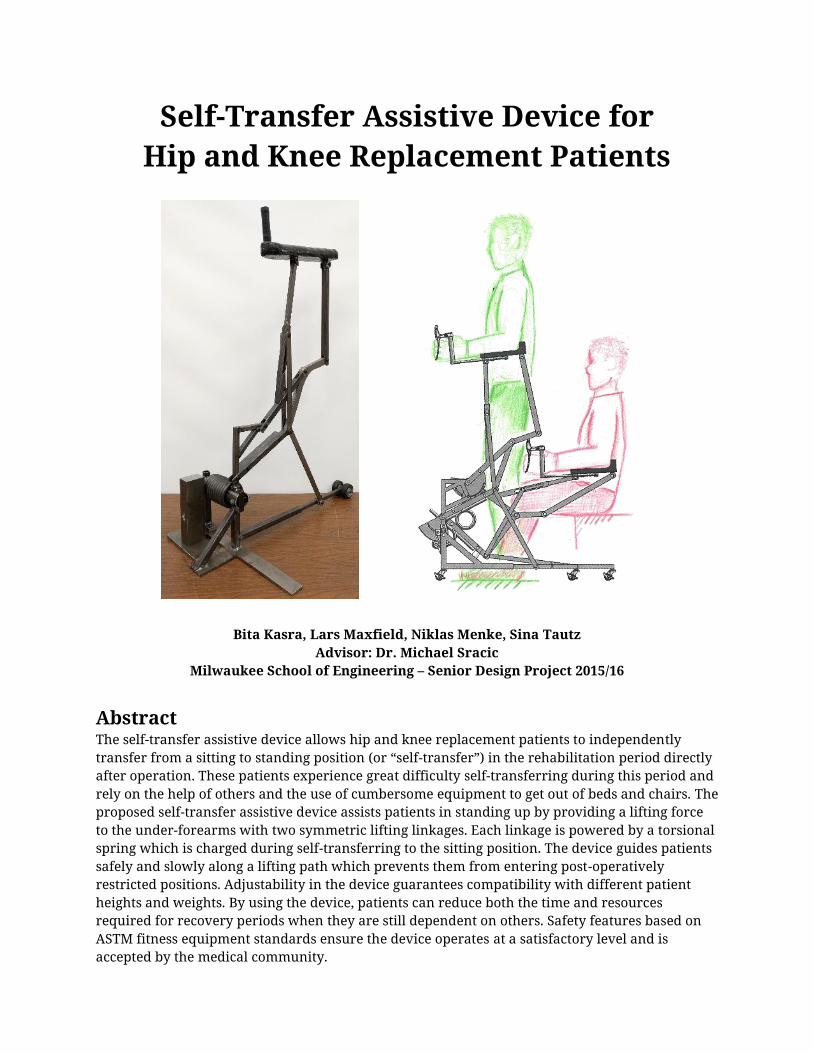
Self-Transfer Assistive Device for Hip and Knee Replacement Patients
Bita Kasra, Lars Maxfield, Niklas Menke, Sina Tautz Advisor: Dr. Michael Sracic
Milwaukee School of Engineering – Senior Design Project 2015/16
Abstract The self-transfer assistive device allows hip and knee replacement patients to independently transfer from a sitting to standing position (or “self-transfer”) in the rehabilitation period directly after operation. These patients experience great difficulty self-transferring during this period and rely on the help of others and the use of cumbersome equipment to get out of beds and chairs. The proposed self-transfer assistive device assists patients in standing up by providing a lifting force to the under-forearms with two symmetric lifting linkages. Each linkage is powered by a torsional spring which is charged during self-transferring to the sitting position. The device guides patients safely and slowly along a lifting path which prevents them from entering post-operatively restricted positions. Adjustability in the device guarantees compatibility with different patient heights and weights. By using the device, patients can reduce both the time and resources required for recovery periods when they are still dependent on others. Safety features based on ASTM fitness equipment standards ensure the device operates at a satisfactory level and is accepted by the medical community.
1
Introduction
1.1. Recognition of Need Recent advances in medical implants allow patients to receive full knee and hip replacements. Although the long term outcomes of such operations are often highly beneficial, one of the most troublesome limitations for patients directly after operation is the ability to transfer between seated and standing positions (referred to as “self-transferring”) [1]. These patients are in a weakened state from the operation such that their general lower body strength is poor, and are therefore dependent on nurses, caretakers, and/or devices during rehabilitation [2]. Devices which are currently used for assistance—such as walkers and crutches—do not fulfill the special needs of hip and knee replacement patients [2]. A device must be developed which assists patients in self-transferring, thus increasing their independence and eliminating the need for supervision.
1.2. Existing Solutions There are a range of devices on the market today that allow individuals to self-transfer; however, these existing solutions are not specifically designed for hip and knee replacement patients. Current devices often require an additional caretaker, and are intended to fully lift individuals and keep them upright in the standing position. Additionally, these devices are cumbersome and rely on external power sources. Hip and knee replacement patients have difficulties in self-transferring, while standing itself does not pose a direct challenge. For these reasons, medical institutions instead use simpler and cheaper methods such as walkers, crutches, and canes for hip and knee replacement patients [1].
These popular devices, which are not specifically designed for hip and knee replacement patients, still require a considerable amount of physical strength when used for self-transferring. Furthermore, the healthy counterpart of the replaced joint is significantly overloaded as the patient cannot yet put the regular load on their replaced joint. A solution is necessary which addresses the needs of hip and knee replacement patients and solves the major disadvantages of crutches and walkers while still maintaining the advantages which make those devices so popular.
Design Approach
2.1. Design Selection and Specifications The recognition of hip and knee replacement patients’ needs and the use of a formal design process led to the proposal of the self-transfer assistive device. The first step of the design selection process was an analysis of the essential functions necessary for a self-transferring device. After identifying the key functional elements of the device, multiple solutions to each function were collected and organized to generate a variety of possible design approaches. All design approaches were then quantitatively evaluated to determine the most favorable solution.
The design process also resulted in the establishment of specifications for the favorable solution, the most significant of which are successfully met by the final design. These significant design specifications state that the device:
Primarily lifts the patient by pushing underneath the forearms and elbow; provides secondary lifting by hoisting the body around the back.
Prevents the patient from moving into postoperatively restricted positions. Supports a patient weight range of 50–100 kg (110–220 lbs.) and height range of 1.50–1.90
m (4’11”–6’3”). Is driven by either a pulley, mechanical spring, or a compressed air spring system.
2
Stores the lifting energy using springs which are “charged” by the weight of the patient when sitting down.
Features extendible base supports to prevent the device from tipping backwards. Provides a means of braking the device at any position with hand levers. Has a maximum width of 0.81 m (32 in.) and height of 2.03 m (80 in.). Has a maximum weight of 20 kg (44 lbs.).
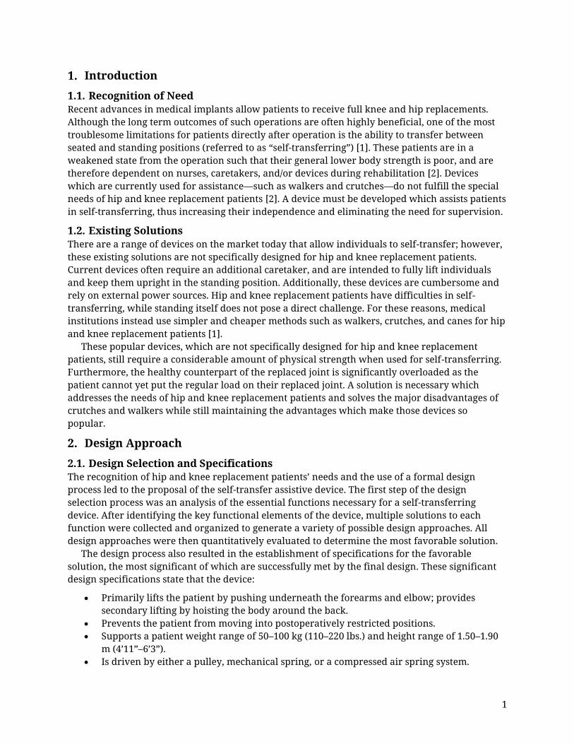
2.2. Lifting Method and Curve The development and analysis of the final device design relied on the identification of the most comfortable assistive lifting method. Research and experiments involving various arm positions and force application areas showed that the most comfortable arm position for self-transferring is a shoulder/elbow angle of 0°/90° [3] (depicted in Figure 2 (left)) with a lifting force applied to the under-forearms. This position ensured the most comfortable self-transfer assistance.
Along with the lifting method, the curve along which the lifting force is delivered was a critical basis for the final design. Experiments were conducted with different user heights to find the lifting path(s) which prevent movement into post-operatively restricted positions (e.g., hip bending of more than 90° [2]). A 0°/90° shoulder/elbow arm angle was maintained throughout the experiments to ensure a constant under-forearm force application. These experiments produced two major results:
1. It is possible to provide assistance for self-transferring with the optimal arm position and force application while preventing movement into post-operatively restricted positions.
2. The lifting path that the shorter patient must follow is simply a portion of the taller patient’s lifting path.
Figure 1. (Left) Shoulder/ elbow positions for force applications from [3]; (right) experimentally determined lifting path
3
Based on these results, patients of different heights can use the same universal lifting path, with variation only in the “amount” of the curve that is used. The final design uses this universal lifting path; however, the experiments showed that the required vertical position of this path varies with patient height. If a shorter patient uses a design geared towards taller patients, they could be lifted up too high and thus increasing the possibility of injuries. To meet the height compatibility specification, the final design provides adjustability for patients with different heights.
2.3. Linkage Design To achieve the lifting curve and force application method, a linkage assembly was designed. The location of the lifting linkage (referred to as the “spatial footprint”) is a significant constraint in the linkage design. To meet the requirements of compatibility with various sitting surfaces and furniture, as well observe dimensional and portability limitations, the spatial footprint of the lifting linkage (and the final design in general) is limited to the area as shown in Figure 2 (left).
The required linkage was developed using dimensional synthesis to meet the following linkage requirements:
An “arm linkage” (see Figure 2 (right)) that follows the defined lifting curve and maintains horizontality, meeting the lifting method criteria.
A single degree of freedom mechanism which requires a single drive, reducing complexity and cost.
Dimensional synthesis achieved the desired output motion and determined the required input motion and linkage lengths. Figure 2 (left) shows the geometry of the designed eight-bar linkage which achieves the lifting method and spatial footprint criteria. The arm linkage (marked red in Figure 2 (left)) supports the under-forearm loading from the patient. The frame points of the mechanism are located in front of the patient and the spatial footprint of the mechanism during the entire lifting curve does not exceed the defined area.
Figure 2. (Left) Allowable spatial footprint for the device; (right) final eight-bar linkage geometry
4
2.4. Static Loading on Patient Body The analysis of the joint moments was based on a quasi-static approach and then validated through research. Research shows that the mechanical loading on the lower limb joints is equivalent to a static condition (i.e., inertial loads are negligible) if the self-transferring movement lasts longer than 2.5 seconds [4]. The same research also proves that joint moments are at their minimum when the self-transfer movement lasts 3.78 seconds [4]. This is important to note as minimizing joint moments can prevent dislocations and further injuries.
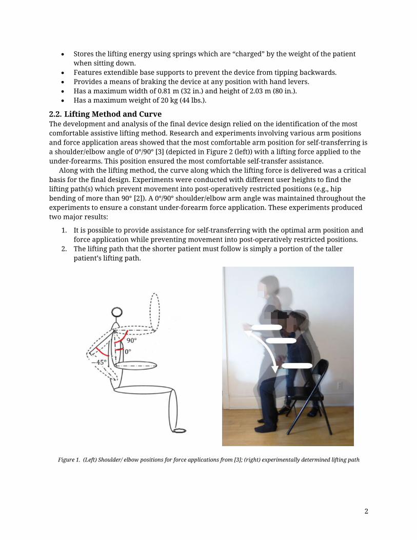
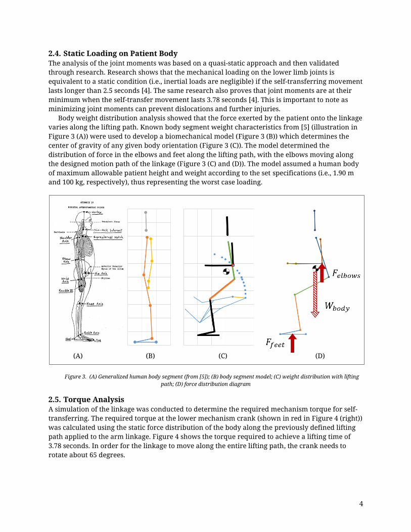
Body weight distribution analysis showed that the force exerted by the patient onto the linkage varies along the lifting path. Known body segment weight characteristics from [5] (illustration in Figure 3 (A)) were used to develop a biomechanical model (Figure 3 (B)) which determines the center of gravity of any given body orientation (Figure 3 (C)). The model determined the distribution of force in the elbows and feet along the lifting path, with the elbows moving along the designed motion path of the linkage (Figure 3 (C) and (D)). The model assumed a human body of maximum allowable patient height and weight according to the set specifications (i.e., 1.90 m and 100 kg, respectively), thus representing the worst case loading.
Figure 3. (A) Generalized human body segment (from [5]); (B) body segment model; (C) weight distribution with lifting path; (D) force distribution diagram
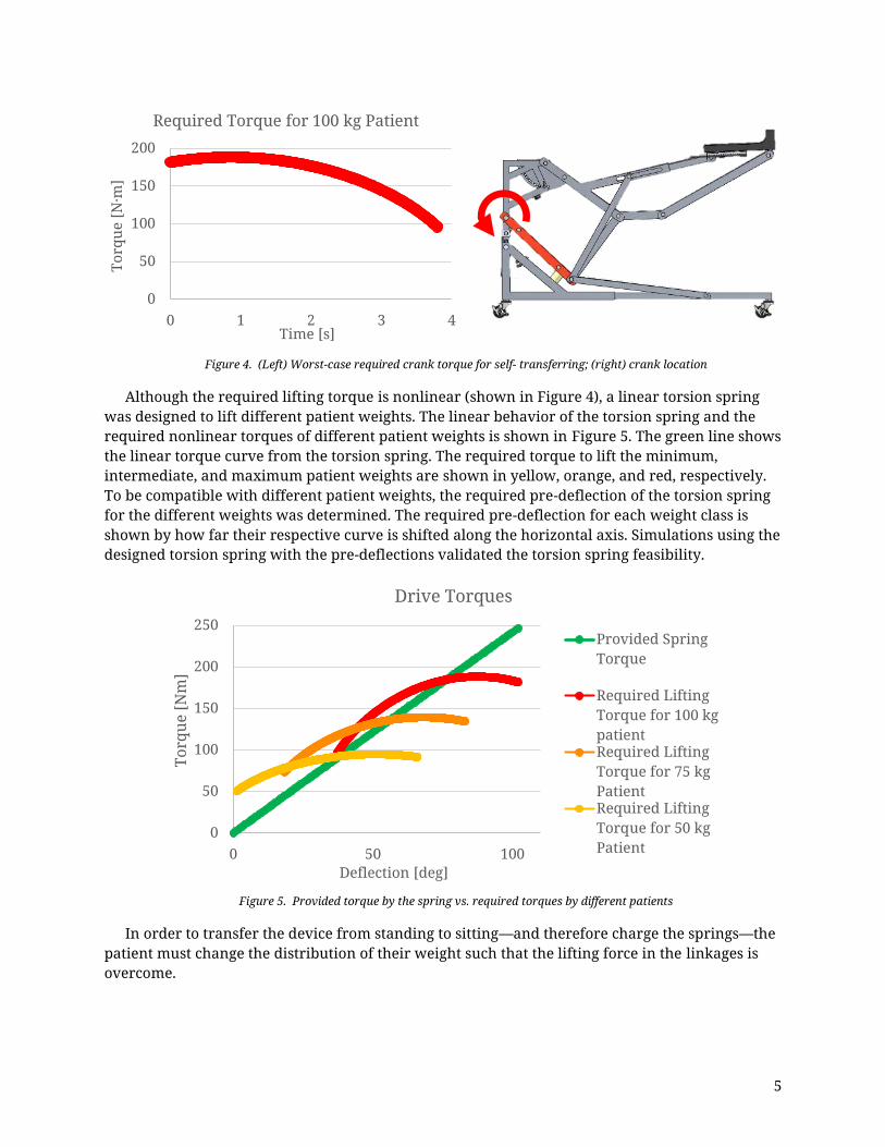
2.5. Torque Analysis A simulation of the linkage was conducted to determine the required mechanism torque for self-transferring. The required torque at the lower mechanism crank (shown in red in Figure 4 (right)) was calculated using the static force distribution of the body along the previously defined lifting path applied to the arm linkage. Figure 4 shows the torque required to achieve a lifting time of 3.78 seconds. In order for the linkage to move along the entire lifting path, the crank needs to rotate about 65 degrees.
Although the required lifting torque is nonlinear (shown in Figure 4), a linear torsion spring was designed to lift different patient weights. The linear behavior of the torsion spring and the required nonlinear torques of different patient weights is shown in Figure 5. The green line shows the linear torque curve from the torsion spring. The required torque to lift the minimum, intermediate, and maximum patient weights are shown in yellow, orange, and red, respectively. To be compatible with different patient weights, the required pre-deflection of the torsion spring for the different weights was determined. The required pre-deflection for each weight class is shown by how far their respective curve is shifted along the horizontal axis. Simulations using the designed torsion spring with the pre-deflections validated the torsion spring feasibility.
Figure 5. Provided torque by the spring vs. required torques by different patients
In order to transfer the device from standing to sitting—and therefore charge the springs—the patient must change the distribution of their weight such that the lifting force in the linkages is overcome.
0
50
100
150
200
0 1 2 3 4
Torq
ue [N
·m]
Time [s]
Required Torque for 100 kg Patient
0
50
100
150
200
250
0 50 100
Torq
ue [N
m]
Deflection [deg]
Drive Torques
Provided SpringTorque
Required LiftingTorque for 100 kgpatientRequired LiftingTorque for 75 kgPatientRequired LiftingTorque for 50 kgPatient
6
Design Description
3.1. Form and Function The basic function of the final design to transfer a patient from sitting to standing is as follows: The patient positions themselves upright at the edge of the sitting surface, moves the device such that their forearms and elbows rest on the two armrests, and secures the back-hoist around their body. With feet shoulder-width apart, forearms horizontal, and upper-arms vertical, the patient grips the brake levers to unlock the device and engage the self-transferring sequence. A pair of torsional springs—charged earlier by the patient while transferring from standing to sitting—deliver a vertical lifting force to each of the patient’s under-forearms through symmetric eight-bar mechanisms. The linkages lift the patient along a curve which safely transfers them to a fully standing position.
Figure 6 shows the completed design and its four main subassemblies. The first main subassembly is the device frame (highlighted in red). The second and third subassemblies are the twin lifting linkages (highlighted in green). The fourth subassembly is the device drive and energy storage (highlighted in blue).
Figure 6. Self-transfer assistive device and designated subassemblies
The components are mainly constructed with square aluminum tubing or solid bar, with the tubing used for the linkages, frame, and structural parts of the drive. Figure 7 shows the first subassembly, the frame, which acts as the “base” of the device and connects the three other subassemblies. The linkages are attached to the upper frame to ensure height adjustability for different patient heights. Each linkage features drives a retractable rear caster which is part of the lower frame. In the sitting position, the rear casters extend rearwards to prevent tipping; in the standing position, they retract into the frame to reduce the footprint of the device. Together with the front casters the device can be easily moved within medical and residential areas while
7
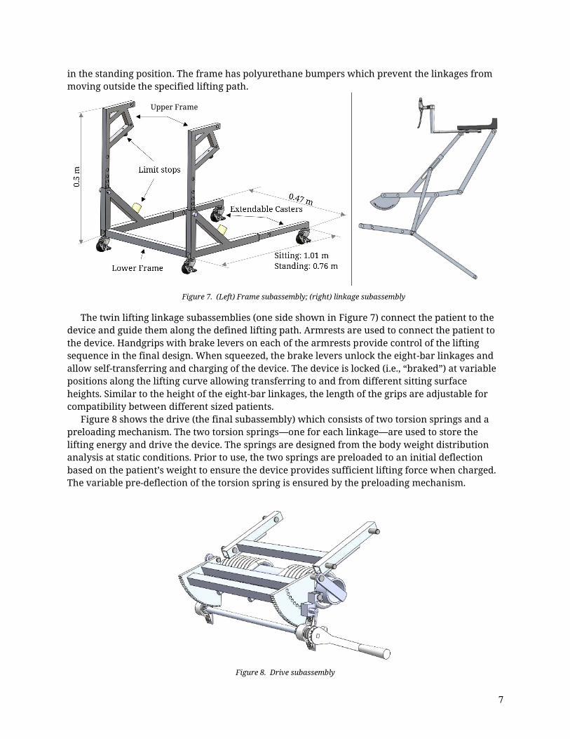
in the standing position. The frame has polyurethane bumpers which prevent the linkages from moving outside the specified lifting path.
The twin lifting linkage subassemblies (one side shown in Figure 7) connect the patient to the device and guide them along the defined lifting path. Armrests are used to connect the patient to the device. Handgrips with brake levers on each of the armrests provide control of the lifting sequence in the final design. When squeezed, the brake levers unlock the eight-bar linkages and allow self-transferring and charging of the device. The device is locked (i.e., “braked”) at variable positions along the lifting curve allowing transferring to and from different sitting surface heights. Similar to the height of the eight-bar linkages, the length of the grips are adjustable for compatibility between different sized patients.
Figure 8 shows the drive (the final subassembly) which consists of two torsion springs and a preloading mechanism. The two torsion springs—one for each linkage—are used to store the lifting energy and drive the device. The springs are designed from the body weight distribution analysis at static conditions. Prior to use, the two springs are preloaded to an initial deflection based on the patient’s weight to ensure the device provides sufficient lifting force when charged. The variable pre-deflection of the torsion spring is ensured by the preloading mechanism.
Figure 8. Drive subassembly
Upper Frame
8
3.2. Safety Features The self-transfer assistive device must be safe for usage by hip and knee replacement patients, and therefore certain safety standards should be followed to ensure market acceptability. The device is designed for rehabilitation of hip and knee replacement patients when their lower body strength is decreased. Since these patients are mobilized by the device, and self-transferring can be seen as a physical activity, ASTM standards on fitness equipment (F2276-10 and F2571-15) can be utilized. These standards should be used in conjunction with other standards to prevent further risk of injuries and ensure proper use of the device.
The device is designed for indoor usage according to certain elements of ASTM F2276-10, which suits the indoor usage of the device within hospitals and homes. To avoid deformations of the device, the frame and linkages were simulated with FEA modeling under worst-case patient loading. The parts of the device are tested using the maximum patient weight of 100 kg. This weight is the required minimum loading for ASTM F2276-10. The FEA simulation of the ASTM F2571-15 testing procedure showed that all parts of the linkage and the frame withstand the applied loading and are considered to be safe for usage.
To ensure a safe and controlled movement of the device, brakes are implemented. In the initial position, the brakes are automatically locked with retention pins. Pulling the brake lever pulls the pin out of the brake plate and unlocks the device. After releasing the brake levers the pin retracts automatically under the force of a compression spring back in the locking position. The same type of pin is used for the adjustment of the pre-deflection in the preloader mechanism. This pin locks the preloading mechanism in position for the usage of the device. The retention pins were chosen for the safety control according to the ASTM F2276-10, which specifies adjustment and locking means. The retention pins also ensure that the locking mechanism cannot be disengaged unless intended per ASTM F2571-15.
The complete design consisting of the frame, linkages, and the drive introduce many corners and edges which pose a safety hazard for patients. Corners and edges must be radiused or chamfered according to the ASTM F2276-10. During the production of the self-transfer assistive device, tests according to the ASTM F2571-15 will ensure the smoothness of all corners and edges. Additionally, a means to close off exposed tube ends must be implemented to ensure safety according to ASTM F2571-15.
The movement of the linkages, together with the frame and drive, feature pinch points and crush areas. For commercial use these pinch points are labeled with safety logos to warn the user about the possible danger. These logos will be designed according to the ASTM F1749-15. To meet the more preferred standard on pinch point safety, guards must be implemented instead of safety labeling. All pinch points and clearances smaller than 60 mm must be guarded according to ASTM F2276-10.
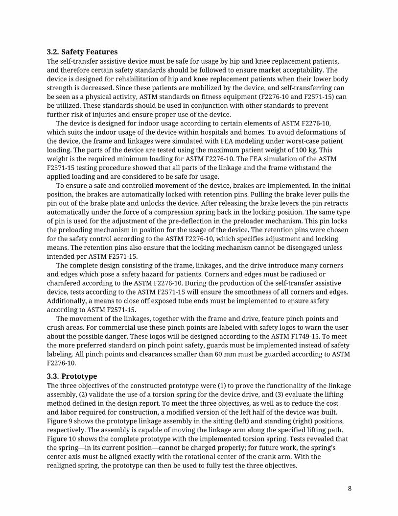
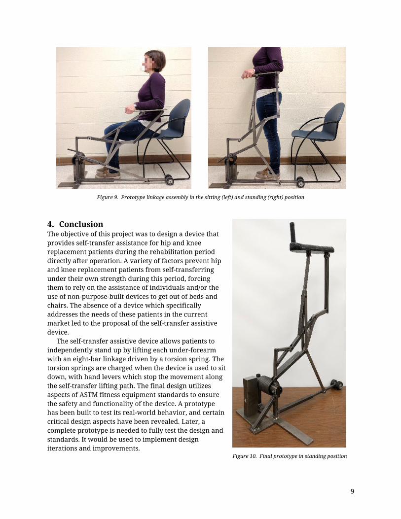
3.3. Prototype The three objectives of the constructed prototype were (1) to prove the functionality of the linkage assembly, (2) validate the use of a torsion spring for the device drive, and (3) evaluate the lifting method defined in the design report. To meet the three objectives, as well as to reduce the cost and labor required for construction, a modified version of the left half of the device was built. Figure 9 shows the prototype linkage assembly in the sitting (left) and standing (right) positions, respectively. The assembly is capable of moving the linkage arm along the specified lifting path. Figure 10 shows the complete prototype with the implemented torsion spring. Tests revealed that the spring—in its current position—cannot be charged properly; for future work, the spring’s center axis must be aligned exactly with the rotational center of the crank arm. With the realigned spring, the prototype can then be used to fully test the three objectives.
9
Figure 9. Prototype linkage assembly in the sitting (left) and standing (right) position
Conclusion The objective of this project was to design a device that provides self-transfer assistance for hip and knee replacement patients during the rehabilitation period directly after operation. A variety of factors prevent hip and knee replacement patients from self-transferring under their own strength during this period, forcing them to rely on the assistance of individuals and/or the use of non-purpose-built devices to get out of beds and chairs. The absence of a device which specifically addresses the needs of these patients in the current market led to the proposal of the self-transfer assistive device.
The self-transfer assistive device allows patients to independently stand up by lifting each under-forearm with an eight-bar linkage driven by a torsion spring. The torsion springs are charged when the device is used to sit down, with hand levers which stop the movement along the self-transfer lifting path. The final design utilizes aspects of ASTM fitness equipment standards to ensure the safety and functionality of the device. A prototype has been built to test its real-world behavior, and certain critical design aspects have been revealed. Later, a complete prototype is needed to fully test the design and standards. It would be used to implement design iterations and improvements.
Figure 10. Final prototype in standing position
10
Acknowledgements The authors would like to express their gratitude to Dr. Michael Sracic for his support and encouragement throughout the project. Appreciation is also extended to ASTM International for their student project grant which partially financed materials for the prototype. Finally, the authors would like to thank Dr. Vincent Prantil, Roger Hajny, Dr. John Pakkala, and Dr. William Farrow for their assistance during the project. ♣ References
[1] Indiana University Health, "Precautions for Total Hip Replacement Patients Only," 2016. [Online]. Available: http://iuhealth.org/images/uploads/Activity_Guidelines.pdf.
[3] M. Farooq and A. A. Khan, "Effects of shoulder rotation combined with elbow flexion on discomfort and EMG activity of ECRB muscle," Internation Journal of Industrial Ergonomics, vol. 44, p. 882–891, 2014.
[4] S. Yoshioka, A. Nagano, D. C. Hay and S. Fukashiro, "The minimum required muscle force for a sit-to-stand task," Journal of Biomechanics, vol. 45, pp. 699-705, 2012.
[5] P. Vint, "Center of Mass (Center of Gravity) of the Human Body," Arizona State University, Phoenix, 2015.