Self-Powered Gyroscope Ball Using a Triboelectric Mechanism
Qiongfeng Shi, Han Wu, Hao Wang, Hanxiang Wu, and Chengkuo Lee*
DOI: 10.1002/aenm.201701300
the versatile aspects of the healthcare monitoring, motion information of body segments, that is, biomechanical parameter monitoring, is one indispensible aspect as useful and opportune knowledge of physical and mental status can be obtained for rehabilitation or diagnostics purpose.[11,12] For example, it can be benefited for the detection of human activity pattern (sitting, walking, or resting), the monitoring and prevention of elderly people fall, the training of hemiparetic patients for limb rehabilitation, etc.[13–15] Nowadays, the motion monitoring system is commonly based on inertial sensor module including multiaxis accelerometer and gyroscope. Commercially available microelectromechanical systems (MEMS) inertial sensor modules have been widely used for acceleration and rotation sensing in healthcare and amusement applications.[16–21] Although MEMS inertial sensors have been commercialized and used
in diversified applications, selfpowered accelerometers using piezoelectric and triboelectric mechanisms have been investigated and considered as novel selfsustained sensors for batteryless applications in internetofthings (IoT), healthcare, and harsh environment monitoring.[22–26]
Among these reported selfpowered accelerometers, devices based on flexible polymer with simple fabrication process and cost effectiveness have been widely investigated. A piezoelectric polyvinylidene fluoride (PVDF) polymer based cantilevertype accelerometer was proposed for oneaxis lowfrequency acceleration detection.[22] A triboelectric and electromagnetic hybrid energy harvester with magnet as movable mass was demonstrated for zaxis acceleration measurement.[23] A popular device configuration for acceleration sensing is symmetric structure, for example, sphericalshaped triboelectric nanogenerator (TENG) was presented for acceleration sensing as well as vibration and water wave energy harvesting.[24,25] The symmetric spherical structure has great potential to enable multiaxis acceleration sensing, however, only oneaxis acceleration measurement was demonstrated. In order to realize the detection of multiaxis acceleration, a 3D acceleration sensor was developed with the structure of three tubeshaped TENGs integrated together along x, y, and z direction.[26] But the detection of threeaxis acceleration is actually achieved by three individual devices rather than one single device, which greatly increases the device size and complexity. Moreover, selfpowered gyroscope has not been reported yet.
Healthcare monitoring systems can provide important health state informa-tion by monitoring the biomechanical parameter or motion of body segments. Triboelectric nanogenerators (TENGs) as self-powered motion sensors have been developed rapidly to convert external mechanical change into electrical signal. However, research effort on using TENGs for multiaxis acceleration sensing is very limited. Moreover, TENG has not been demonstrated for rota-tion sensing to date. Herein, for the first time, a 3D symmetric triboelectric nanogenerator-based gyroscope ball (T-ball) with dual capability of energy harvesting and self-powered sensing is proposed for motion monitoring including multiaxis acceleration and rotation. The T-ball can harvest energy under versatile scenarios and function as self-powered 3D accelerometer with sensitivity of 6.08, 5.87, and 3.62 V g−1 . Furthermore, the T-ball can serve as a self-powered gyroscope for rotation sensing with sensitivity of 3.5 mV so−1. It shows good performance in hand motion recognition and human activity state monitoring applications. The proposed T-ball as a self-powered gyro-scope for advanced motion sensing can pave the way to a self-powered, more accurate, and more complete motion monitoring system.
Q. Shi, H. Wu, Dr. H. Wang, H. Wu, Prof. C. LeeDepartment of Electrical and Computer EngineeringNational University of Singapore4 Engineering Drive 3, Singapore 117576, SingaporeE-mail: [email protected]. Shi, H. Wu, Dr. H. Wang, Prof. C. LeeCenter for Sensors and MEMSNational University of Singapore4 Engineering Drive 3, Singapore 117576, SingaporeQ. Shi, H. Wu, Dr. H. Wang, Prof. C. LeeNational University of Singapore Suzhou Research Institute (NUSRI)Suzhou Industrial Park, Suzhou 215123, ChinaH. WuDepartment of Electronics Engineering and Computer SciencePeking UniversityBeijing 100871, China
Energy Harvesting
1. Introduction
Healthcare monitoring system is playing a more and more important role in our daily life to provide useful health information for disease prevention and treatment.[1–3] A wide variety of sensors have been demonstrated to monitor physiological signs and biomechanical parameters for healthcare monitoring, such as tactile sensor, respiration rate sensor, heart rate sensor, blood pressure sensor, eyeball motion sensor, brain activity sensor and various implantable biomedical sensors, etc.[4–10] Among
In general, selfpowered sensing design or dualpurpose design with energy harvesting and sensing capability is a promising research field to enable longterm and smart motion monitoring system. Herein, a triboelectric nanogenerator based gyroscope ball (Tball) with 3D symmetricity is proposed for selfpowered advanced motion sensing and multimode energy harvesting. The proposed Tball is able to harvest energy from diversified scenarios, such as multiple and random directional vibration, spinning, rotation, rolling, finger tapping/touching, etc. Furthermore, it can function as a selfpowered 3D accelerometer and gyroscope for advanced motion sensing including threeaxis acceleration and rotation. It exhibits good performance in hand motion recognition, showing great potential in amusement, virtual reality, and game control applications. With the excellent sensing capability, the Tball is demonstrated as a selfpowered exercise sensor for human activity monitoring, which can provide useful and realtime information to healthcare motion monitoring system.
2. Design, Theoretical Consideration, and Operation Mechanism
Generally speaking, gyroscope is a sensor that can detect the rotation rate or angular velocity of an object. A traditional gyroscope with 3D symmetric structure of a suspending massive rotor inside three gimbals is shown in Figure S1a (Supporting Information). Besides, MEMS gyroscopes with vibratory mechanical elements to sense the angular velocity have also been proposed and investigated for rotation measurement.[18–21] The basic device configuration of these MEMS gyroscopes includes a suspended proof mass, spring beams, driving electrodes, and sensing electrodes. The operation mechanism is that when the proof mass is driven to vibrate at resonance by electrostatic or electromagnetic force from the driving electrodes, an angular rotation will induce Coriolis force at the driving frequency which can be detected by the sensing electrodes. These MEMS gyroscopes require a vibrating proof mass and actuators to drive it in the resonant state, which causes significant power consumption from external power supply. Toward selfpowered sensing ability, piezoelectric and triboelectric mechanisms provide a promising solution.[22–30] Furthermore, triboelectric mechanism exhibits great merits of high output performance, cost effectiveness, simple device configuration, easy scalability, and a wide range of material selection.[31,32] TENG based on triboelectrification and electrostatic induction between two different materials was first proposed in 2012, and since then has received tremendous research effort in diversified energy harvesting and selfpowered sensing applications.[33–41]
Therefore, by leveraging the advantages of symmetric structure and the merits of triboelectric mechanism, a 3D symmetric Tball for multimode energy harvesting and selfpowered advanced motion sensing is proposed. A conceptual illustration of the Tball integrated with signal processing and communication integrated circuit (IC) is depicted in Figure S1b (Supporting Information) for dual purpose of energy harvesting and wireless selfpowered motion monitoring. The detail device configuration of the Tball with tilted view and crosssectional view is shown in Figure 1a,b. The enlarged view of the layerbylayer
structure is illustrated in Figure 1c. The proposed Tball is constituted of a 3D printing ballshaped frame, four inner Al electrodes covered by polytetrafluoroethylene (PTFE) thin film, four outer Al electrodes covered by polydimethylsiloxane (PDMS), and multiple steel balls encapsulated inside. The outer electrodes are fabricated on the outer surface of Tball to further enhance the energy harvesting capability. The dimension of the Tball is 65 mm in diameter. The multiple small steel balls with diameter of 6.3 mm serve as movable mass and triboelectric layer. The four inner electrodes are denoted as Ex+, Ey+, Ex−, and Ey−, while the four outer electrodes are denoted as E1, E2, E3, and E4 (Figure 1a). Then the facetoface Ex+ and Ex− are connected as the positive and negative input of Ex, while Ey+ and Ey− are connected as the positive and negative input of Ey for energy harvesting and motion sensing. On the other hand, the four outer electrodes are working under single electrode mode for energy harvesting. Figure 1d,e shows the photograph of the Tball before and after the assembling, respectively.
Due to the 3D symmetric ballshaped design, the Tball has the ability to harvest energy from diversified sources and the potential for complex and advanced motion sensing. Although complex motion may exhibit randomdirection movement and rotation, it can always be considered as the integration of linear movement in x, y, and zaxis and rotation. Accordingly, the movement of steel balls inside the Tball can be divided into three major categories—moving along one direction with the inplane (xy plane) vibration, moving along zaxis with outofplane (vertical) vibration, and spinning around the inner surface of the Tball. The operation mechanism of the Tball activated by inplane vibration is depicted in Figure 1f by side view. After contacting with each other, steel balls become positively charged and PTFE becomes negatively charged because of the difference in electron affiliation. When the steel balls move to the left side, electric potential difference appears on the two opposite electrodes and then drives electrons flow from the right electrode to the left electrode until new balance is achieved. Then when the steel balls move from the left side to the middle part and further to the right side, electrons are forced to flow in the opposite direction. Figure 1g presents the schematic illustration of the wire connection and current waveform from Ex when the Tball is vibrating in x direction. Only inner electrodes and the PTFE thin film are shown in the schematic diagram to clearly indicate the wire connection. When the Tball is solely vibrating along x or y direction, there will be only one output in the corresponding direction since there is no electric potential difference in the other direction. But when the Tball is vibrating with a certain angle θ with respect to xaxis (0° < θ < 90°), there will be two outputs from both Ex and Ey. Thus, the Tball has the capability to harvest energy from inplane vibration source in random and multiple directions. For outofplane vibration, the operation mechanism is demon strated in Figure S2a (Supporting Information). The electric potential difference on all the four inner electrodes is the same in vertical vibration, thus in this case the four inner electrodes are connected in single electrode mode. It should be noted that the inner electrodes are connected in single electrode mode only in vertical vibration motion, otherwise they are connected as Ex and Ey. When the Tball vibrates downward, the steel balls depart from the bottom surface of the Tball, driving electrons flow from the Al electrode to ground to balance
the electric potential difference. Then when the Tball vibrates upward, the steel balls contact with the bottom surface of the Tball again and electrons are driven to flow back. Schematic illustration of the wire connection and current waveform of vertical vibration is shown in Figure S2b (Supporting Information).
The operation mechanism of the Tball when it is activated by spinning motion is depicted in Figure 1h by top view. When the Tball is spinning clockwise in x–y plane around a circle with its own orientation maintaining the same, the steel balls then undergo circular movement around the inner surface.
Adv. Energy Mater. 2017, 1701300
Figure 1. Device configuration and operation mechanism of the T-ball. a) Schematic diagram showing the T-ball device structure. Ex+, Ey+, Ex−, and Ey− are inner electrodes on the inner surface and E1, E2, E3, and E4 are outer electrodes on the outer surface. b) Cross-sectional view of the T-ball. c) Enlarged view of the device structure layer. d) Photograph of the T-ball before assembling. e) Photograph of the T-ball after assembling. f) Operation mechanism of the T-ball under in-plane vibration along x-axis. Only inner electrodes and PTFE film are shown. g) Wire connection (only inner electrodes and PTFE film are shown) and output current waveform corresponding to different stages of the in-plane vibration. h) Operation mechanism under spinning motion. i) Wire connection and output current waveform corresponding to different stages of the spinning motion.
Thus, electric potential difference is induced on all the four inner electrons (Ex+, Ey+, Ex−, and Ey−) in a consecutive way. The generated electric potential difference then drives electrons flow between the corresponding inner electrodes and thereby current is generated. The clockwise circular movement of the steel balls results in Ex current waveform with one quarter phase shift in front of Ey current waveform, since the steel balls move in the direction of Ex+, Ey+, Ex−, and Ey−. Figure 1i shows the wire connection and current waveform from Ex and Ey when the Tball is spinning clockwise. If the Tball is spinning in an anticlockwise direction, the current waveform of Ey will then be one quarter faster in phase.
The Tball not only can harvest energy from versatile vibration and rotation sources, it can also harvest the human tapping and touching energy. The operation mechanism of the Tball for finger tapping energy harvesting is illustrated in Figure S2c,d (Supporting Information). The four outer electrodes are connected in single electrode mode to harvest the energy more effectively. When an active object such as human finger contacts with the PDMS surface, triboelectrification arises between the human skin and the PDMS surface. Most common active objects like human skin, metal surface, and fabric materials is more positive in the triboelectric series compared to PDMS, thus PDMS surface turns into negatively charged and the human finger becomes positively charged. After the triboelectrification, when the human finger is approaching the PDMS surface, electric potential difference drives electrons flow from ground to the Al electrode. Then when the human finger is moving away from the PDMS surface, electrons is driven to flow back to ground.
3. Results and Discussion
3.1. Characterization and Optimization of the T-Ball
After the fabrication of electrodes and dielectric layers, multiple steel balls as movable mass and triboelectric layer need to be put inside the Tball. The size and the number of the steel balls to be included is a key parameter which has significant impact on the output performance. Thus, the Tball is first characterized and optimized in terms of the size and the number of steel balls. The Tball is tested under the setup shown in Figure 2a, where it is periodically vibrated along xaxis with frequency of 3.2 Hz and displacement amplitude of 3 cm. The output voltage and current from Ex is measured and plotted in Figure 3b,c when the number of different diameter steel balls (6.3, 8.0, and 9.5 mm) increases. Figure 3d,e shows the output voltage and current waveform with different number of 6.3 mm steel balls. It can be seen that the output voltage and current first increases with the number of steel balls and then saturates at certain level for all three types of steel balls. The larger diameter steel balls show faster output increment rate due to the faster increment of effective contact area. The analytical model of contact area and simulation of potential distribution can be found in Figure S3 (Supporting Information). The output voltage and current of three different diameter steel balls saturates at the same level but with different number of 12 (9.5 mm), 17 (8.0 mm), and 25 (6.3 mm). Due to the ballshaped curve surface of the Tball,
extra steel balls beyond that only stack on the previous steel balls during vibration, without actually contributing to the effective contact area. Thus, the output voltage and current saturates at the number of 12, 17, and 25 for steel balls of 9.5, 8.0, and 6.3 mm, respectively. From the analytical model results, it can be observed that the effective contact area is dominated by the shadow area of the steel balls. For the Tball, 6.3 mm steel balls with number of 25 are adopted as the optimized condition for energy harvesting and sensing measurements unless specified.
3.2. Multimode Energy Harvesting Capability
Due to the high symmetricity, the Tball can harvest energy under a wide variety of circumstances. As discussed before, the steel balls movements inside the Tball can be divided into inplane vibration, outofplane vibration, and circular spinning. In reality, various ambient motions acted on the Tball can cause these movements of the steel balls. Ambient vibrations are common energy sources that can be found from machine movement, vehicle engine, water wave, various human motion, etc. Normally, these vibrations exhibit multiple and random directions. In order to demonstrate its capability of multimode energy harvesting, the Tball is tested under different circumstances as illustrated in Figure 3. Both the output voltage and current performance from Ex and Ey are measured for all the circumstances. As shown in Figure 3a–c, the Tball is first tested under inplane vibration along 30°, 60°, and 45° with respect to xaxis. When the Tball is vibrating with angle of 30°, output from Ex is larger than that from Ey since the vibration component in x direction is larger than in y direction. Similarly for vibration angle of 60°, output from Ey is larger than that from Ex. With vibration angle of 45°, output from Ex and Ey shows the same level. Besides the inplane vibration, the Tball is then tested under outofplane vibration as demonstrated in Figure 3d–f with acceleration of 3 and 5 g. The acceleration is measured by a commercial accelerometer (ADXL325, Analog Devices) assembled on the Tball. For the vertical vibration, electrodes Ex+ and Ey+ are connected as single electrode to measure the output voltage and current. When the acceleration level increases, the output voltage and current also increases. The above results show that the Tball has the capability to harvest both inplane and outofplane vibration energy from multiple and irregular directions.
Similar to vibration motion, spinning or rotating motion is also common in the ambient environment, for example, rotating wheels, moving fans, operating washing machine, swerving, etc. Figure 3g–i presents the results when the Tball is spinning with diameter of 1, 3, and 5 cm while its axis orientation maintains the same. When the spinning diameter increases from 1 to 5 cm, output voltage and current increases from 8 to 32 V and from 0.15 to 0.35 µA, respectively. When the steel balls undergo circular movement, the centripetal force is
c2f mrω=
(1)
where fc is the centripetal force required to maintain the circular movement, m is the object mass, r is the radius of curvature, and ω is angular velocity. When the spinning diameter
increases, higher centripetal force is required to sustain the circular movement. In order to achieve higher centripetal force, the steel balls need to move to higher position on the inner surface of the Tball, resulting in larger contact area and higher output. The systematic analysis of steel balls’ position inside the Tball during spinning is shown in Table S1 and Figure S4 (Supporting Information). The testing results of rotating are depicted in Figure 3j–l when the Tball is rotating along its zaxis vertically and horizontally. Output from horizontal rotation is higher than that from vertical rotation due to the larger contact area of steel balls on the boatshaped electrodes when the Tball is rotated with its zaxis placed horizontally. Rolling can be treated as a special case of rotation without fixed rotation axis. The testing results of the Tball when it is rolling
slowly and fast on a table are illustrated in Figure 3m–o. Higher output is generated with fast rolling. The detail characterization of the Tball under inplane vibration and spinning is shown in Figure S5 (Supporting Information). The photograph of the testing setup is shown in Figure S6 (Supporting Information). Energy harvesting results from outer electrode and output power are shown in Figure S7 (Supporting information).
3.3. Self-Powered Advanced Motion Sensor
Apart from the multimode energy harvesting capability, the 3D symmetric Tball is ideally suitable for selfpowered advanced motion sensing. When operating as selfpowered sensor, the
Adv. Energy Mater. 2017, 1701300
Figure 2. Characterization and optimization of the T-ball. a) Schematic illustration showing the testing setup of the x-axis vibration. b) The relationship of the output voltage and the number of steel balls with different size. c) The relationship of the output current and the number of steel balls with different size. d) Output voltage waveform with different number of 6.3 mm steel balls. e) Output current waveform with different number of 6.3 mm steel balls.
Figure 3. Multimode energy harvesting capability of the T-ball. a–c) Schematic illustration, output voltage and current of the T-ball when it is vibrating in-plane along 30°, 60°, and 45° with respect to x-axis. d–f) Schematic illustration, output voltage and current of the T-ball when it is vibrating in out-of-plane direction with acceleration of 3 and 5 g. g–i) Schematic illustration, output voltage and current of the T-ball when it is spinning with diameter of 1, 3, and 5 cm. j–l) Schematic illustration, output voltage and current of the T-ball when it is rotating vertically and horizontally. m–o) Schematic illustration, output voltage and current of the T-ball when it is rolling slowly and fast.
outer electrodes of the Tball are grounded to minimize the electrostatic interference. Conventional TENGs normally can only achieve oneaxis acceleration sensing, but the proposed Tball is able to function as a selfpowered 3D accelerometer. As shown in Figure 4a, acceleration with different magnitude is applied on the Tball in x, y, and zaxis direction. The output voltage from Ex and Ey is measured when x and yaxis acceleration is applied, while the output voltage from single electrode Ex+ and Ey+ is measured with zaxis acceleration is applied. Figure 4b–d presents the relationship of output voltage and x, y, and z acceleration when different number of 6.3 mm steel ball is encapsulated inside. When the Tball is vibrating in x direction, voltage from Ex first increases significantly with xaxis acceleration but then gradually saturates as shown in Figure 4b. This can be attributed to the large increment of contact area with small acceleration, but only small increment of contact area is achieved with large acceleration. Larger number of steel balls shows higher output. The linear range and sensitivity for xaxis acceleration sensing with 25 steel balls is 4.87 g and 6.08 V g−1. It can be observed that voltage from Ey is almost 0 since no electric potential difference is generated on electrode Ey+ and Ey− when the Tball is vibrating along x direction. The small voltage from Ey with increasing x acceleration is caused by the fabrication error and alignment error, that is, the four electrodes are not perfectly symmetric and the alignment of the vibration is not exactly in x direction. Measurement results are similar to yaxis acceleration, where the linear sensing range and sensitivity with 25 steel balls is 5.06 g and 5.87 V g−1. For zaxis acceleration, voltage is generated from both Ex+ and Ey+
when the steel balls start to vibrate. When z acceleration is less than 1 g, almost no output voltage is observed from Ex+ and Ey+, because the acceleration is not able to separate the steel balls from the bottom surface of the Tball. When z acceleration further increases, output voltage increases with sensitivity (25 steel balls) of 3.62 V g−1. The Tball as a 3D accelerometer exhibits better or comparable sensitivity than the previously reported TENGbased accelerometers,[23,24,26] showing great capability for various applications in motion sensing.
The Tball can be used for selfpowered human gesture or hand motion recognition. Figure 4e shows the Tball held by a human hand for moving direction monitoring. A commercial accelerometer (ADXL325, Analog Devices) is assembled on a small breadboard and attached on top of the Tball to measure the actual acceleration. Output voltage from Ex and Ey is connected to oscilloscope for waveform recording when the Tball is moving left, right, forward, and backward. After each movement, the Tball always moves back to the original position, waiting for the next movement. Figure 4f illustrates acceleration from commercial accelerometer as well as the output voltage waveform from Ex and Ey. When moving left, Vx first shows a positive peak and then several vibrating peaks while Vy shows no signal since acceleration is in x direction. When moving right, Vx first shows a negative peak and then several vibrating peaks while Vy also shows no signal. The difference in the output voltage waveform is because when the Tball is moving to the left side, the steel balls are first swung to electrode Ex+ and then vibrates, thus a positive peak is generated at the beginning. When the Tball is moving to the right side,
Adv. Energy Mater. 2017, 1701300
Figure 4. Self-powered 3D accelerometer and hand motion recognition. a) Schematic illustration of the wire connection and applied acceleration in x, y, z direction. Only inner electrodes and PTFE film are shown in the schematic illustration. b) The output voltage from Ex and Ey with different x-axis acceleration. c) The output voltage from Ex and Ey with different y-axis acceleration. d) The output voltage from Ex and Ey with different z-axis accelera-tion. e) Photograph of the T-ball for different moving direction sensing. f) The acceleration level and the output voltage waveform from the T-ball when it moves left, right, forward, and backward. Red arrows in the graph indicate the first generated peak.
the steel balls are first swung to electrode Ex− and thus a negative peak is generated at the beginning. The same phenomenon happens when the Tball is moving forward and backward except that the acceleration is in the ydirection.
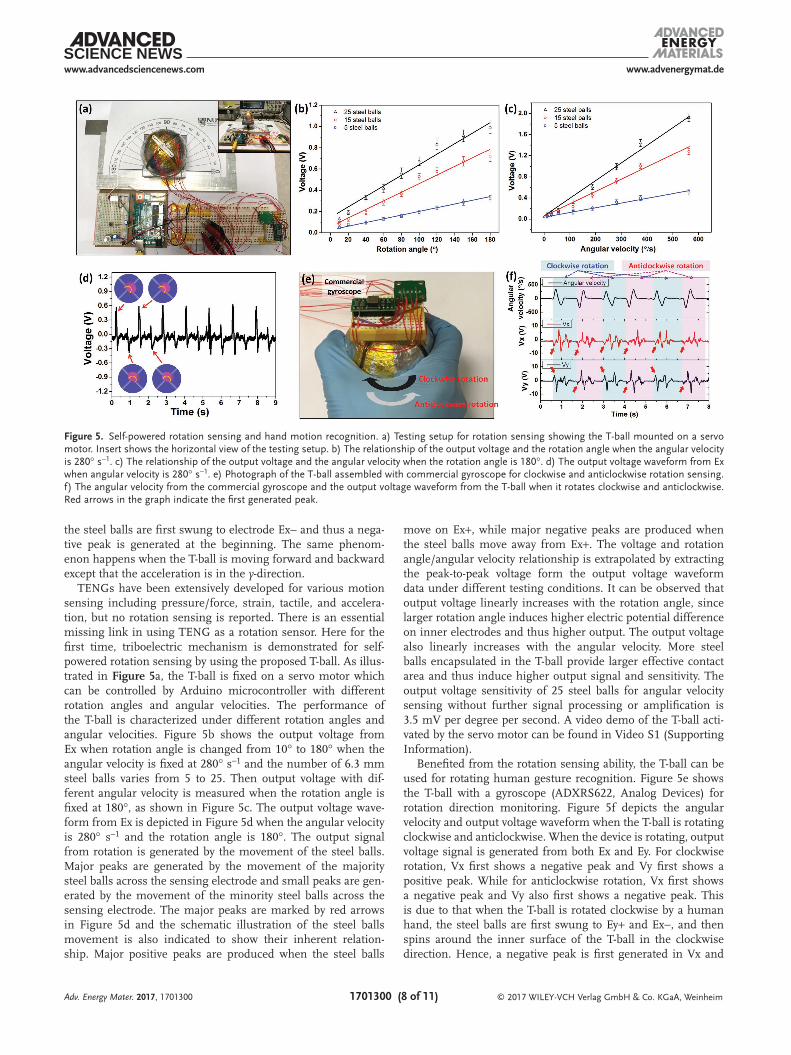
TENGs have been extensively developed for various motion sensing including pressure/force, strain, tactile, and acceleration, but no rotation sensing is reported. There is an essential missing link in using TENG as a rotation sensor. Here for the first time, triboelectric mechanism is demonstrated for selfpowered rotation sensing by using the proposed Tball. As illustrated in Figure 5a, the Tball is fixed on a servo motor which can be controlled by Arduino microcontroller with different rotation angles and angular velocities. The performance of the Tball is characterized under different rotation angles and angular velocities. Figure 5b shows the output voltage from Ex when rotation angle is changed from 10° to 180° when the angular velocity is fixed at 280° s−1 and the number of 6.3 mm steel balls varies from 5 to 25. Then output voltage with different angular velocity is measured when the rotation angle is fixed at 180°, as shown in Figure 5c. The output voltage waveform from Ex is depicted in Figure 5d when the angular velocity is 280° s−1 and the rotation angle is 180°. The output signal from rotation is generated by the movement of the steel balls. Major peaks are generated by the movement of the majority steel balls across the sensing electrode and small peaks are generated by the movement of the minority steel balls across the sensing electrode. The major peaks are marked by red arrows in Figure 5d and the schematic illustration of the steel balls movement is also indicated to show their inherent relationship. Major positive peaks are produced when the steel balls
move on Ex+, while major negative peaks are produced when the steel balls move away from Ex+. The voltage and rotation angle/angular velocity relationship is extrapolated by extracting the peaktopeak voltage form the output voltage waveform data under different testing conditions. It can be observed that output voltage linearly increases with the rotation angle, since larger rotation angle induces higher electric potential difference on inner electrodes and thus higher output. The output voltage also linearly increases with the angular velocity. More steel balls encapsulated in the Tball provide larger effective contact area and thus induce higher output signal and sensitivity. The output voltage sensitivity of 25 steel balls for angular velocity sensing without further signal processing or amplification is 3.5 mV per degree per second. A video demo of the Tball activated by the servo motor can be found in Video S1 (Supporting Information).
Benefited from the rotation sensing ability, the Tball can be used for rotating human gesture recognition. Figure 5e shows the Tball with a gyroscope (ADXRS622, Analog Devices) for rotation direction monitoring. Figure 5f depicts the angular velocity and output voltage waveform when the Tball is rotating clockwise and anticlockwise. When the device is rotating, output voltage signal is generated from both Ex and Ey. For clockwise rotation, Vx first shows a negative peak and Vy first shows a positive peak. While for anticlockwise rotation, Vx first shows a negative peak and Vy also first shows a negative peak. This is due to that when the Tball is rotated clockwise by a human hand, the steel balls are first swung to Ey+ and Ex−, and then spins around the inner surface of the Tball in the clockwise direction. Hence, a negative peak is first generated in Vx and
Figure 5. Self-powered rotation sensing and hand motion recognition. a) Testing setup for rotation sensing showing the T-ball mounted on a servo motor. Insert shows the horizontal view of the testing setup. b) The relationship of the output voltage and the rotation angle when the angular velocity is 280° s−1. c) The relationship of the output voltage and the angular velocity when the rotation angle is 180°. d) The output voltage waveform from Ex when angular velocity is 280° s−1. e) Photograph of the T-ball assembled with commercial gyroscope for clockwise and anticlockwise rotation sensing. f) The angular velocity from the commercial gyroscope and the output voltage waveform from the T-ball when it rotates clockwise and anticlockwise. Red arrows in the graph indicate the first generated peak.
a positive peak is first generated in Vy. Then when the Tball is rotated anticlockwise, the steel balls are first swung to Ey− and Ex−, thus a negative peak is first generated in Vx and a negative peak is first generated in Vy. The detail schematic illustration of first peak generation mechanism for different moving and rotation directions is depicted in Figure S8 (Supporting Information). When the Tball is operated under different moving and rotation direction, different waveforms of Vx and Vy can be identified by a signal processing circuit and can serve as controlling signal for motion recognition system. The Tball shows great potential for the applications in smart controlling system, virtual reality, game control, etc. A video demo of the Tball for different moving and rotation direction sensing can be found in Video S2 (Supporting Information).
Monitoring our daily activity state or exercise level is important in healthcare monitoring system for rehabilitation or diagnostics. The Tball as a selfpowered exercise sensor can be mounted on human hand for different exercise state sensing, as shown in Figure 6a. The xdirection of the Tball is aligned with the moving direction of the human. When standing, walking slowly, walking fast, or running, the output voltage from Ex is plotted in Figure 6b along with the corresponding acceleration level. Due to the increment of acceleration, the output voltage of the Tball also increases. Other than just judging from the output voltage waveform, frequency domain analysis can also be performed to determine which exercise the tester is undergoing, as depicted in Figure S6 (Supporting Information). No
significant output peak in frequency domain can be observed when the tester is standing still, while a small peak with amplitude of 0.17 at 0.80 Hz appears when the tester is walking slowly. When the tester is walking fast, the peak amplitude increases to 0.62 and frequency increases to 1.00 Hz. For running, amplitude and frequency further increase to 1.00 and 1.35 Hz, respectively. The amplitude in the frequency domain is normalized to the amplitude when the tester is running. Based on the frequency domain analysis results, different types of exercise can be easily determined from the output signal of the Tball. A video demo of the Tball mounted on human hand as an exercise sensor can be found in Video S3 (Supporting Information). The Tball can also function as a dropping sensor to measure the free dropping distance. Figure 6c,d shows the output voltage of the Tball when it is dropped from dropping distance of 5 to 25 cm. The output voltage increases with the dropping distance since higher dropping distance induces higher backward acceleration on the Tball. Figure 6e depicts the output voltage of the Tball after 10 000 cycles of vibration, showing the robustness of the Tball for longterm applications. The device performance under extreme environmental conditions such as high temperature and high humidity is very important for many sensing applications. To demonstrate the sensing stability of the Tball, its performance is measured and compared in underwater environment with different temperature, as shown in Figure 6f. The output voltage performance of the Tball in air and in water with different temperature is
Figure 6. Self-powered human exercise sensor and stability test. a) Schematic illustration of different type of exercises with the T-ball mounted on hand. b) The acceleration level and the output voltage from the T-ball when the tester is standing, walking slowly, walking fast, and running. c) The output voltage from the T-ball when it is dropped to ground from different height distance. d) The relationship between the output voltage and the dropping distance. e) The output voltage after 10 000 cycles of vibration showing the robustness of the T-ball. f) Photograph of the T-ball for underwater test. g) Output voltage waveform of the T-ball in air and in water with different temperature. h) Output voltage performance comparison of the T-ball in air and in water with different temperature.
depicted in Figure 6g,h. From the results, it can be seen that the performance of the Tball is almost constant in underwater environment with temperature increases from 30 to 90 °C, compared to the performance in air. Its ability to operate in high temperature, high humidity, and underwater environment promotes a wide range of extended applications such as underwater sensor and water wave energy harvester.
4. Conclusion
In this study, a 3D symmetric Tball is proposed for multimode energy harvesting and selfpowered advanced motion (multiaxis acceleration and rotation) sensing. A selfpowered gyroscope for rotation sensing based on triboelectric mechanism is demonstrated using the Tball for the first time. The proposed Tball can harvest energy under versatile circumstances, such as multiple and random directional vibration, spinning, rotation, rolling, finger tapping/touching, etc. It is highly adaptable and practicable to harvest energy from various types of ambient energy source. Besides, the symmetric structure enables the Tball for selfpowered 3D acceleration sensing with x, y, and z direction sensitivity of 6.08, 5.87, and 3.62 V g−1 without signal processing by IC circuit. Moreover, the Tball can work as a selfpowered gyroscope for rotation sensing and hand motion recognition with the angular velocity sensitivity of 3.5 mV so−1, which shows great potential in smart control system, virtual reality, and game control applications. In addition, the Tball mounted on human hand exhibits good performance as a selfpowered exercise sensor, which provides useful realtime information for the healthcare monitoring system. Looking forward, the proposed Tball can be a key component paving the way to eventually realize a selfpowered, more complete, and more accurate motion monitoring system.
5. Experimental SectionFabrication of the T-Ball: Two hemispherical frames were first
fabricated by 3D printing with the material of Vero clear. The next steps were carried out on both frames. Al foil pieces were then attached on both the inner surface and the outer surface of the frames as electrodes. After that, PTFE thin film was attached on top of the inner Al electrodes. Kapton tape was utilized to enhance the attachment of the PTFE thin film on the hemispherical frame. PDMS solution with mass ratio of 10:1 (elastomer base to curing agent) was mixed and coated on the outer surface of the frame and then cured for 2 h at 60 °C. Next, multiple steel balls were put inside of one hemispherical structure as movable mass to create triboelectrification and electrostatic induction. Finally, the two hemispherical structures were aligned with each other and sealed as a complete T-ball.
Characterization of the T-Ball: Voltage measurement was conducted by connecting the output signal to a DSO-X3034A oscilloscope (Agilent) with a high impedance probe of 100 MΩ. Current measurement was conducted by connecting the output signal to a low noise SR570 current pre-amplifier (Stanford Research Systems). For measuring the acceleration magnitude, a commercial accelerometer ADXL325 (Analog Devices) was assembled with the T-ball. Angular velocity was measured by attaching a commercial gyroscope ADXRS622 (Analog Devices) on top of the T-ball. To generate rotation motion with controllable rotation angle and angular velocity, a servo motor connected to a programmable Arduino UNO was used.
Supporting InformationSupporting Information is available from the Wiley Online Library or from the author.
AcknowledgementsThis work was supported by grants from the National Research Foundation (NRF) Competitive Research Programme (CRP) project “Self-Powered Body Sensor Network for Disease Management and Prevention Oriented Healthcare” (R-263-000-A27-281), NRF CRP project “Peripheral Nerve Prostheses: A Paradigm Shift in Restoring Dexterous Limb Function” (R-719-000-001-281), Ministry of Education (MOE) Faculty Research Committee (FRC) Grant (R-263-000-B56-112) “Thermoelectric Power Generator (TEG) Based Self-Powered ECG Plaster – System Integration (Part 3),” and National Natural Science Foundation of China under Grant No. 61474078 at NUS (Suzhou) Research Institute, Suzhou, China.
Conflict of InterestThe authors declare no conflict of interest.
Keywordstriboelectric nanogenerators, gyroscope, balls, self-powered systems, energy harvesting
Received: May 12, 2017Revised: June 11, 2017
Published online:
[1] A. Darwish, A. E. Hassanien, Sensors 2011, 11, 5561.[2] Y. Zang, F. Zhang, C.-A. Di, D. Zhu, Mater. Horiz. 2015, 2, 140.[3] H. Alemdar, C. Ersoy, Comput. Networks 2010, 54, 2688.[4] B. C.-K. Tee, A. Chortos, A. Berndt, A. K. Nguyen, A. Tom,
A. McGuire, Z. C. Lin, K. Tien, W.-G. Bae, H. Wang, Science 2015, 350, 313.
[6] Z. Li, Z. L. Wang, Adv. Mater. 2011, 23, 84.[7] X. Wang, Y. Gu, Z. Xiong, Z. Cui, T. Zhang, Adv. Mater. 2014, 26, 1336.[8] S. Lee, R. Hinchet, Y. Lee, Y. Yang, Z. H. Lin, G. Ardila, L. Montès,
M. Mouis, Z. L. Wang, Adv. Funct. Mater. 2014, 24, 1163.[9] J. Viventi, D.-H. Kim, L. Vigeland, E. S. Frechette, J. A. Blanco,
Y.-S. Kim, A. E. Avrin, V. R. Tiruvadi, S.-W. Hwang, A. C. Vanleer, Nat. Neurosci. 2011, 14, 1599.
[10] E. Meng, R. Sheybani, Lab Chip 2014, 14, 3233.[11] H. Sveistrup, J. NeuroEng. Rehabil. 2004, 1, 10.[12] R. Baker, J. NeuroEng. Rehabil. 2006, 3, 4.[13] D. M. Karantonis, M. R. Narayanan, M. Mathie, N. H. Lovell,
B. G. Celler, IEEE Trans. Inf. Technol. Biomed. 2006, 10, 156.[14] T. Shany, S. J. Redmond, M. R. Narayanan, N. H. Lovell, IEEE Sens. J.
2012, 12, 658.[15] P. Maciejasz, J. Eschweiler, K. Gerlach-Hahn, A. Jansen-Troy,
S. Leonhardt, J. NeuroEng. Rehabil. 2014, 11, 3.[16] M.-H. Tsai, Y.-C. Liu, W. Fang, J. Microelectromech. Syst. 2012, 21,
1329.[17] R. Xu, S. Zhou, W. J. Li, IEEE Sens. J. 2012, 12, 1166.[18] F. Ayazi, K. Najafi, J. Microelectromech. Syst. 2001, 10, 169.
[19] K. Liu, W. Zhang, W. Chen, K. Li, F. Dai, F. Cui, X. Wu, G. Ma, Q. Xiao, J. Micromech. Microeng. 2009, 19, 113001.
[20] H. Xie, G. K. Fedder, J. Aerospace Eng. 2003, 16, 65.[21] STMicroelectronics, MEMS and Sensors: iNEMO-Inertial Modules,
http://www.st.com/content/st_com/en/products/mems-and-sen-sors/inemo-inertial-modules.html?querycriteria=productId=SC1448 (accessed: May 2017).
[22] R. Schulze, T. Gessner, M. Heinrich, M. Schueller, R. Forke, D. Billep, M. Sborikas, M. Wegener, presented at 2012 Int. Symp. Applications of Ferroelectrics, held jointly with 2012 European Conf. Applications of Polar Dielectrics and 2012 Int. Symp. Piezoresponse Force Microscopy and Nanoscale Phenomena in Polar Materials, Aveiro, Portugal, 9–13 July, 2012.
[23] R. K. Gupta, Q. Shi, L. Dhakar, T. Wang, C. H. Heng, C. Lee, Sci. Rep. 2017, 7, 41396.
[24] H. Zhang, Y. Yang, Y. Su, J. Chen, K. Adams, S. Lee, C. Hu, Z. L. Wang, Adv. Funct. Mater. 2014, 24, 1401.
[25] X. Wang, S. Niu, Y. Yin, F. Yi, Z. You, Z. L. Wang, Adv. Energy Mater. 2015, 5, 1501467.
[26] Y. K. Pang, X. H. Li, M. X. Chen, C. B. Han, C. Zhang, Z. L. Wang, ACS Appl. Mater. Interfaces 2015, 7, 19076.
[27] L. Persano, C. Dagdeviren, Y. Su, Y. Zhang, S. Girardo, D. Pisignano, Y. Huang, J. A. Rogers, Nat. Commun. 2013, 4, 1633.
[28] Q. Shi, T. Wang, T. Kobayashi, C. Lee, Appl. Phys. Lett. 2016, 108, 193902.
[29] Q. Shi, T. Wang, C. Lee, Sci. Rep. 2016, 6, 24946.[30] K. I. Park, J. H. Son, G. T. Hwang, C. K. Jeong, J. Ryu, M. Koo,
I. Choi, S. H. Lee, M. Byun, Z. L. Wang, Adv. Mater. 2014, 26, 2514.
[31] F.-R. Fan, L. Lin, G. Zhu, W. Wu, R. Zhang, Z. L. Wang, Nano Lett. 2012, 12, 3109.
[32] K. Y. Lee, M. K. Gupta, S.-W. Kim, Nano Energy 2015, 14, 139.[33] F.-R. Fan, Z.-Q. Tian, Z. L. Wang, Nano Energy 2012, 1, 328.[34] H. Wang, Z. Xiang, P. Giorgia, X. Mu, Y. Yang, Z. L. Wang, C. Lee,
Nano Energy 2016, 23, 80.[35] K. Zhao, Z. L. Wang, Y. Yang, ACS Nano 2016, 10, 9044.[36] X. Wang, Y. Yang, Nano Energy 2017, 32, 36.[37] Q. Shi, H. Wang, T. Wang, C. Lee, Nano Energy 2016, 30, 450.[38] X. Cao, Y. Jie, N. Wang, Z. L. Wang, Adv. Energy Mater. 2016, 6,
1600665.[39] H. Zhu, N. Wang, Y. Xu, S. Chen, M. Willander, X. Cao, Z. L. Wang,
Adv. Funct. Mater. 2016, 26, 3029.[40] L. Dhakar, P. Pitchappa, F. E. H. Tay, C. Lee, Nano Energy 2016, 19,
532.[41] Q. Zheng, B. Shi, F. Fan, X. Wang, L. Yan, W. Yuan, S. Wang, H. Liu,