2 SEMESTER III SL. No. COURSE CODE COURSE TITLE L T P C THEORY 1. MA6351 Transforms and Partial Differential Equations 3 1 0 4 2. EE6352 Electrical Engineering and Instrumentation 3 1 0 4 3. EC6301 Object Oriented Programming and Data Structures 3 0 0 3 4. EC6302 Digital Electronics 3 0 0 3 5. EC6303 Signals and Systems 3 1 0 4 6. EC6304 Electronic Circuits- I 3 1 0 4 PRACTICAL 7. EC6311 Analog and Digital Circuits Laboratory 0 0 3 2 8. EC6312 OOPS and Data Structures Laboratory 0 0 3 2 TOTAL 18 4 6 26 SEMESTER IV SL. No. COURSE CODE COURSE TITLE L T P C THEORY 1. MA6451 Probability and Random Processes 3 1 0 4 2. EC6401 Electronic Circuits II 3 0 0 3 3. EC6402 Communication Theory 3 0 0 3 4. EC6403 Electromagnetic Fields 3 1 0 4 5. EC6404 Linear Integrated Circuits 3 0 0 3 6. EC6405 Control System Engineering 3 0 0 3 PRACTICAL 7. EC6411 Circuit and Simulation Integrated Laboratory 0 0 3 2 8. EC6412 Linear Integrated Circuit Laboratory 0 0 3 2 9. EE6461 Electrical Engineering and Control System Laborator y 0 0 3 2 TOTAL 18 2 9 26
Transcript
2
SEMESTER III
SL. No.
COURSE CODE
COURSE TITLE L T P C
THEORY
1. MA6351 Transforms and Partial Differential Equations
3 1 0 4
2. EE6352 Electrical Engineering and Instrumentation 3 1 0 4
3. EC6301 Object Oriented Programming and Data Structures
3 0 0 3
4. EC6302 Digital Electronics
3 0 0 3
5. EC6303 Signals and Systems
3 1 0 4
6. EC6304 Electronic Circuits- I
3 1 0 4
PRACTICAL
7. EC6311 Analog and Digital Circuits Laboratory 0 0 3 2
8. EC6312 OOPS and Data Structures Laboratory 0 0 3 2
TOTAL 18 4 6 26
SEMESTER IV
SL. No.
COURSE CODE
COURSE TITLE L T P C
THEORY
1. MA6451 Probability and Random Processes 3 1 0 4
8. EC6412 Linear Integrated Circuit Laboratory 0 0 3 2
9. EE6461 Electrical Engineering and Control System Laboratory
0 0 3 2
TOTAL 18 2 9 26
32
MA6351 TRANSFORMS AND PARTIAL DIFFERENTIAL EQUATIONS L T P C 3 1 0 4 OBJECTIVES:
To introduce Fourier series analysis which is central to many applications in engineering apart from its use in solving boundary value problems.
To acquaint the student with Fourier transform techniques used in wide variety of situations.
To introduce the effective mathematical tools for the solutions of partial differential equations that model several physical processes and to develop Z transform techniques for discrete time systems.
UNIT I PARTIAL DIFFERENTIAL EQUATIONS 9+3 Formation of partial differential equations – Singular integrals -- Solutions of standard types of first order partial differential equations - Lagrange‟s linear equation -- Linear partial differential equations of second and higher order with constant coefficients of both homogeneous and non-homogeneous types.
UNIT II FOURIER SERIES 9+3 Dirichlet‟s conditions – General Fourier series – Odd and even functions – Half range sine series – Half range cosine series – Complex form of Fourier series – Parseval‟s identity – Harmonic analysis.
UNIT III APPLICATIONS OF PARTIAL DIFFERENTIAL EQUATIONS 9+3 Classification of PDE – Method of separation of variables - Solutions of one dimensional wave equation – One dimensional equation of heat conduction – Steady state solution of two dimensional equation of heat conduction (excluding insulated edges).
UNIT IV FOURIER TRANSFORMS 9+3 Statement of Fourier integral theorem – Fourier transform pair – Fourier sine and cosine transforms – Properties – Transforms of simple functions – Convolution theorem – Parseval‟s identity.
UNIT V Z - TRANSFORMS AND DIFFERENCE EQUATIONS 9+3 Z- transforms - Elementary properties – Inverse Z - transform (using partial fraction and residues) – Convolution theorem - Formation of difference equations – Solution of difference equations using Z - transform.
TOTAL (L:45+T:15): 60 PERIODS OUTCOMES:
The understanding of the mathematical principles on transforms and partial differential equations would provide them the ability to formulate and solve some of the physical problems of engineering.
TEXT BOOKS: 1. Veerarajan. T., "Transforms and Partial Differential Equations", Second reprint, Tata Mc Graw Hill
Education Pvt. Ltd., New Delhi, 2012. 2. Grewal. B.S., "Higher Engineering Mathematics", 42nd Edition, Khanna Publishers, Delhi, 2012. 3. Narayanan.S., Manicavachagom Pillay.T.K and Ramanaiah.G "Advanced Mathematics for
Engineering Students" Vol. II & III, S.Viswanathan Publishers Pvt Ltd. 1998.
REFERENCES: 1. Bali.N.P and Manish Goyal, "A Textbook of Engineering Mathematics", 7th Edition, Laxmi
Publications Pvt Ltd , 2007. 2. Ramana.B.V., "Higher Engineering Mathematics", Tata Mc-Graw Hill Publishing Company Limited,
New Delhi, 2008. 3. Glyn James, "Advanced Modern Engineering Mathematics", 3rd Edition, Pearson Education, 2007. 4. Erwin Kreyszig, "Advanced Engineering Mathematics", 8th Edition, Wiley India, 2007.
33
5. Ray Wylie. C and Barrett.L.C, "Advanced Engineering Mathematics" Sixth Edition, Tata Mc Graw Hill Education Pvt Ltd, New Delhi, 2012.
6. Datta.K.B., "Mathematical Methods of Science and Engineering", Cengage Learning India Pvt Ltd, Delhi, 2013.
EE6352 ELECTRICAL ENGINEERING AND INSTRUMENTATION L T P C
3 1 0 4
OBJECTIVES:
To introduce three phase supply and power measurement.
To understand concepts in electrical generators, motors and transformers.
To introduce power generation, transmission and distribution concepts.
To learn basic measurement concepts.
To learn the concepts of electronic measurements.
To learn about importance of digital instruments in measurements UNIT I DC MACHINES 9 Three phase circuits, a review. Construction of DC machines – Theory of operation of DC generators – Characteristics of DC generators- Operating principle of DC motors – Types of DC motors and their characteristics – Speed control of DC motors- Applications. UNIT II TRANSFORMER 9 Introduction – Single phase transformer construction and principle of operation – EMF equation of transformer-Transformer no–load phasor diagram –– Transformer on–load phasor diagram –– Equivalent circuit of transformer – Regulation of transformer –Transformer losses and efficiency-All day efficiency –auto transformers. UNIT III INDUCTION MACHINES AND SYNCHRONOUS MACHINES 9 Principle of operation of three-phase induction motors – Construction –Types – Equivalent circuit –Construction of single-phase induction motors – Types of single phase induction motors – Double revolving field theory – starting methods - Principles of alternator – Construction details – Types – Equation of induced EMF – Voltage regulation. Methods of starting of synchronous motors – Torque equation – V curves – Synchronous motors.
UNIT IV BASICS OF MEASUREMENT AND INSTRUMENTATION 9 Static and Dynamic Characteristics of Measurement – Errors in Measurement - Classification of Transducers – Variable resistive – Strainguage, thermistor RTD – transducer - Variable Capacitive Transducer – Capacitor Microphone - Piezo Electric Transducer – Variable Inductive transducer – LVDT, RVDT
UNIT V ANALOG AND DIGITAL INSTRUMENTS 9 DVM, DMM – Storage Oscilloscope. Comparison of Analog and Digital Modes of operation, Application of measurement system, Errors. Measurement of R, L and C, Wheatstone, Kelvin, Maxwell, Anderson, Schering and Wien bridges Measurement of Inductance, Capacitance, Effective resistance at high frequency, Q-Meter. TOTAL (L:45+T:15): 60 PERIODS
34
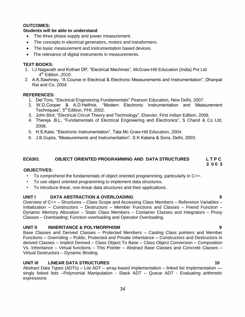
OUTCOMES: Students will be able to understand
The three phase supply and power measurement.
The concepts in electrical generators, motors and transformers.
The basic measurement and instrumentation based devices.
The relevance of digital instruments in measurements. TEXT BOOKS: 1. I.J Nagarath and Kothari DP, “Electrical Machines”, McGraw-Hill Education (India) Pvt Ltd
4th Edition ,2010 2. A.K.Sawhney, “A Course in Electrical & Electronic Measurements and Instrumentation”, Dhanpat
Rai and Co, 2004. REFERENCES:
1. Del Toro, “Electrical Engineering Fundamentals” Pearson Education, New Delhi, 2007. 2. W.D.Cooper & A.D.Helfrick, “Modern Electronic Instrumentation and Measurement
Techniques”, 5th Edition, PHI, 2002. 3. John Bird, “Electrical Circuit Theory and Technology”, Elsevier, First Indian Edition, 2006. 4. Thereja .B.L, “Fundamentals of Electrical Engineering and Electronics”, S Chand & Co Ltd,
2008.
5. H.S.Kalsi, “Electronic Instrumentation”, Tata Mc Graw-Hill Education, 2004.
6. J.B.Gupta, “Measurements and Instrumentation”, S K Kataria & Sons, Delhi, 2003.
EC6301 OBJECT ORIENTED PROGRAMMING AND DATA STRUCTURES L T P C 3 0 0 3
OBJECTIVES:
• To comprehend the fundamentals of object oriented programming, particularly in C++.
• To use object oriented programming to implement data structures.
• To introduce linear, non-linear data structures and their applications.
UNIT I DATA ABSTRACTION & OVERLOADING 9 Overview of C++ – Structures – Class Scope and Accessing Class Members – Reference Variables – Initialization – Constructors – Destructors – Member Functions and Classes – Friend Function – Dynamic Memory Allocation – Static Class Members – Container Classes and Integrators – Proxy Classes – Overloading: Function overloading and Operator Overloading. UNIT II INHERITANCE & POLYMORPHISM 9 Base Classes and Derived Classes – Protected Members – Casting Class pointers and Member Functions – Overriding – Public, Protected and Private Inheritance – Constructors and Destructors in derived Classes – Implicit Derived – Class Object To Base – Class Object Conversion – Composition Vs. Inheritance – Virtual functions – This Pointer – Abstract Base Classes and Concrete Classes – Virtual Destructors – Dynamic Binding. UNIT III LINEAR DATA STRUCTURES 10 Abstract Data Types (ADTs) – List ADT – array-based implementation – linked list implementation –– singly linked lists –Polynomial Manipulation - Stack ADT – Queue ADT - Evaluating arithmetic expressions
35
UNIT IV NON-LINEAR DATA STRUCTURES 9 Trees – Binary Trees – Binary tree representation and traversals – Application of trees: Set representation and Union-Find operations – Graph and its representations – Graph Traversals – Representation of Graphs – Breadth-first search – Depth-first search - Connected components.
UNIT V SORTING and SEARCHING 8 Sorting algorithms: Insertion sort - Quick sort - Merge sort - Searching: Linear search –Binary Search
TOTAL: 45 PERIODS
OUTCOMES: Upon completion of the course, students will be able to:
Explain the concepts of Object oriented programming.
Write simple applications using C++. Discuss the different methods of organizing large amount of data.
TEXT BOOKS: 1. Deitel and Deitel, “C++, How To Program”, Fifth Edition, Pearson Education, 2005. 2. Mark Allen Weiss, “Data Structures and Algorithm Analysis in C++”, Third Edition, Addison-
Wesley, 2007.
REFERENCES: 1. Bhushan Trivedi, “Programming with ANSI C++, A Step-By-Step approach”, Oxford University
Press, 2010. 2. Goodrich, Michael T., Roberto Tamassia, David Mount, “Data Structures and Algorithms in
C++”, 7th Edition, Wiley. 2004. 3. Thomas H. Cormen, Charles E. Leiserson, Ronald L. Rivest and Clifford Stein, "Introduction to
Algorithms", Second Edition, Mc Graw Hill, 2002. 4. Bjarne Stroustrup, “The C++ Programming Language”, 3rd Edition, Pearson Education, 2007. 5. Ellis Horowitz, Sartaj Sahni and Dinesh Mehta, “Fundamentals of Data Structures in C++”,
Galgotia Publications, 2007.
EC6302 DIGITAL ELECTRONICS L T P C 3 0 0 3
OBJECTIVES:
To introduce basic postulates of Boolean algebra and shows the correlation between Boolean expressions
To introduce the methods for simplifying Boolean expressions
To outline the formal procedures for the analysis and design of combinational circuits
and sequential circuits
To introduce the concept of memories and programmable logic devices.
To illustrate the concept of synchronous and asynchronous sequential circuits UNIT I MINIMIZATION TECHNIQUES AND LOGIC GATES 9 Minimization Techniques: Boolean postulates and laws – De-Morgan‟s Theorem - Principle of Duality - Boolean expression - Minimization of Boolean expressions –– Minterm – Maxterm - Sum of Products (SOP) – Product of Sums (POS) – Karnaugh map Minimization – Don‟t care conditions – Quine - Mc Cluskey method of minimization.
36
Logic Gates: AND, OR, NOT, NAND, NOR, Exclusive–OR and Exclusive–NOR Implementations of Logic Functions using gates, NAND–NOR implementations – Multi level gate implementations- Multi output gate implementations. TTL and CMOS Logic and their characteristics – Tristate gates
UNIT III SEQUENTIAL CIRCUITS 9 Latches, Flip-flops - SR, JK, D, T, and Master-Slave – Characteristic table and equation –Application table – Edge triggering – Level Triggering – Realization of one flip flop using other flip flops – serial adder/subtractor- Asynchronous Ripple or serial counter – Asynchronous Up/Down counter - Synchronous counters – Synchronous Up/Down counters – Programmable counters – Design of Synchronous counters: state diagram- State table –State minimization –State assignment - Excitation table and maps-Circuit implementation - Modulo–n counter, Registers – shift registers - Universal shift registers – Shift register counters – Ring counter – Shift counters - Sequence generators.
UNIT IV MEMORY DEVICES 9 Classification of memories – ROM - ROM organization - PROM – EPROM – EEPROM –EAPROM, RAM – RAM organization – Write operation – Read operation – Memory cycle - Timing wave forms – Memory decoding – memory expansion – Static RAM Cell- Bipolar RAM cell – MOSFET RAM cell – Dynamic RAM cell –Programmable Logic Devices – Programmable Logic Array (PLA) - Programmable Array Logic (PAL) – Field Programmable Gate Arrays (FPGA) - Implementation of combinational logic circuits using ROM, PLA, PAL
UNIT V SYNCHRONOUS AND ASYNCHRONOUS SEQUENTIAL CIRCUITS 9 Synchronous Sequential Circuits: General Model – Classification – Design – Use of Algorithmic State Machine – Analysis of Synchronous Sequential Circuits
Asynchronous Sequential Circuits: Design of fundamental mode and pulse mode circuits – Incompletely specified State Machines – Problems in Asynchronous Circuits – Design of Hazard Free Switching circuits. Design of Combinational and Sequential circuits using VERILOG.
TOTAL: 45 PERIODS
OUTCOMES: Students will be able to:
Analyze different methods used for simplification of Boolean expressions.
Design and implement Combinational circuits.
Design and implement synchronous and asynchronous sequential circuits.
Write simple HDL codes for the circuits.
TEXT BOOK: 1. M. Morris Mano, “Digital Design”, 4th Edition, Prentice Hall of India Pvt. Ltd., 2008 / Pearson
Education (Singapore) Pvt. Ltd., New Delhi, 2003.
37
REFERENCES: 1. John F.Wakerly, “Digital Design”, Fourth Edition, Pearson/PHI, 2008 2. John.M Yarbrough, “Digital Logic Applications and Design”, Thomson Learning, 2006. 3. Charles H.Roth. “Fundamentals of Logic Design”, 6th Edition, Thomson Learning, 2013. 4. Donald P.Leach and Albert Paul Malvino, “Digital Principles and Applications”, 6th Edition, TMH,
2006. 5. Thomas L. Floyd, “Digital Fundamentals”, 10th Edition, Pearson Education Inc, 2011 6. Donald D.Givone, “Digital Principles and Design”, TMH, 2003.
EC6303 SIGNALS AND SYSTEMS L T P C 3 1 0 4
OBJECTIVES:
To understand the basic properties of signal & systems and the various methods of classification
To learn Laplace Transform &Fourier transform and their properties
To know Z transform & DTFT and their properties
To characterize LTI systems in the Time domain and various Transform domains
UNIT I CLASSIFICATION OF SIGNALS AND SYSTEMS 9 Continuous time signals (CT signals) - Discrete time signals (DT signals) - Step, Ramp, Pulse, Impulse, Sinusoidal, Exponential, Classification of CT and DT signals - Periodic & Aperiodic signals, Deterministic & Random signals, Energy & Power signals - CT systems and DT systems- Classification of systems – Static & Dynamic, Linear & Nonlinear, Time-variant & Time-invariant, Causal & Noncausal, Stable & Unstable.
UNIT II ANALYSIS OF CONTINUOUS TIME SIGNALS 9 Fourier series analysis-spectrum of Continuous Time (CT) signals- Fourier and Laplace Transforms in CT Signal Analysis - Properties.
UNIT III LINEAR TIME INVARIANT- CONTINUOUS TIME SYSTEMS 9 Differential Equation-Block diagram representation-impulse response, convolution integrals-Fourier and Laplace transforms in Analysis of CT systems
UNIT IV ANALYSIS OF DISCRETE TIME SIGNALS 9 Baseband Sampling - DTFT – Properties of DTFT - Z Transform – Properties of Z Transform
UNIT V LINEAR TIME INVARIANT-DISCRETE TIME SYSTEMS 9 Difference Equations-Block diagram representation-Impulse response - Convolution sum- Discrete Fourier and Z Transform Analysis of Recursive & Non-Recursive systems TOTAL (L:45+T:15): 60 PERIODS OUTCOMES: Upon the completion of the course, students will be able to:
Analyze the properties of signals & systems
Apply Laplace transform, Fourier transform, Z transform and DTFT in signal analysis
Analyze continuous time LTI systems using Fourier and Laplace Transforms
Analyze discrete time LTI systems using Z transform and DTFT
38
TEXT BOOK: 1. Allan V.Oppenheim, S.Wilsky and S.H.Nawab, “Signals and Systems”, Pearson, 2007.
REFERENCES: 1. B. P. Lathi, “Principles of Linear Systems and Signals”, Second Edition, Oxford, 2009. 2. R.E.Zeimer, W.H.Tranter and R.D.Fannin, “Signals & Systems - Continuous and Discrete”,
Pearson, 2007. 3. John Alan Stuller, “An Introduction to Signals and Systems”, Thomson, 2007. 4. M.J.Roberts, “Signals & Systems Analysis using Transform Methods & MATLAB”, Tata McGraw
Hill, 2007.
EC6304 ELECTRONIC CIRCUITS – I L T P C
3 1 0 4 OBJECTIVES: The student should be made to
Learn about biasing of BJTs and MOSFETs
Design and construct amplifiers
Construct amplifiers with active loads
Study high frequency response of all amplifiers UNIT I POWER SUPPLIES AND BIASING OF DISCRETE BJT AND MOSFET 9 Rectifiers with filters- DC Load line, operating point, Various biasing methods for BJT-Design-Stability-Bias compensation, Thermal stability, Design of biasing for JFET, Design of biasing for MOSFET UNIT II BJT AMPLIFIERS 9 Small signal Analysis of Common Emitter-AC Load line, Voltage swing limitations, Common collector and common base amplifiers – Differential amplifiers- CMRR- Darlington Amplifier- Bootstrap technique - Cascaded stages - Cascode Amplifier-Large signal Amplifiers – Class A , Class B and Class C Power Amplifiers . UNIT III JFET AND MOSFET AMPLIFIERS 9 Small signal analysis of JFET amplifiers- Small signal Analysis of MOSFET and JFET, Common source amplifier, Voltage swing limitations, Small signal analysis of MOSFET and JFET Source follower and Common Gate amplifiers, - BiMOS Cascode amplifier UNIT IV FREQUENCY ANALYSIS OF BJT AND MOSFET AMPLIFIERS 9 Low frequency and Miller effect, High frequency analysis of CE and MOSFET CS amplifier, Short circuit current gain, cut off frequency – fα and fβ unity gain and Determination of bandwidth of single stage and multistage amplifiers UNIT V IC MOSFET AMPLIFIERS 9 IC Amplifiers- IC biasing Current steering circuit using MOSFET- MOSFET current sources- PMOS and NMOS current sources. Amplifier with active loads - enhancement load, Depletion load and PMOS and NMOS current sources load- CMOS common source and source follower- CMOS differential amplifier- CMRR. TOTAL (L: 45+T: 15): 60 PERIODS
39
OUTCOMES: Upon Completion of the course, the students will be able to: Design circuits with transistor biasing. Design simple amplifier circuits. Analyze the small signal equivalent circuits of transistors. Design and analyze large signal amplifiers. TEXT BOOK: 1. Donald .A. Neamen, Electronic Circuit Analysis and Design –2nd Edition,Tata Mc Graw Hill, 2009.
REFERENCES: 1. Adel .S. Sedra, Kenneth C. Smith, “Micro Electronic Circuits”, 6th Edition, Oxford University Press, 2010. 2. David A., “Bell Electronic Devices and Circuits”, Oxford Higher Education Press, 5th Edition, 2010 3. Behzad Razavi, “Design of Analog CMOS Integrated Circuits”, Tata Mc Graw Hill, 2007. 4. Paul Gray, Hurst, Lewis, Meyer “Analysis and Design of Analog Integrated Circuits”, 4th Edition ,John Willey & Sons 2005 5. Millman.J. and Halkias C.C, “Integrated Electronics”, Mc Graw Hill, 2001. 6. D.Schilling and C.Belove, “Electronic Circuits”, 3rd Edition, Mc Graw Hill, 1989. 7. Robert L. Boylestad and Louis Nasheresky, “Electronic Devices and Circuit Theory”, 10th Edition, Pearson Education / PHI, 2008.
EC6311 ANALOG AND DIGITAL CIRCUITS LABORATORY L T P C
0 0 3 2 OBJECTIVES: The student should be made to:
Study the characteristic of CE,CB and CC Amplifier
Learn the frequency response of CS Amplifiers
Study the Transfer characteristic of differential amplifier
Perform experiment to obtain the bandwidth of single stage and multistage amplifiers
Perform SPICE simulation of Electronic Circuits
LIST OF ANALOG EXPERIMENTS: 1. Half Wave and Full Wave Rectifiers, Filters, Power supplies 2. Frequency Response of CE, CB, CC and CS amplifiers 3. Darlington Amplifier 4. Differential Amplifiers- Transfer characteristic, CMRR Measurement 5. Cascode / Cascade amplifier 6. Class A and Class B Power Amplifiers 7. Determination of bandwidth of single stage and multistage amplifiers 8. Spice Simulation of Common Emitter and Common Source amplifiers
LIST OF DIGITAL EXPERIMENTS 9. Design and implementation of code converters using logic gates
(i) BCD to excess-3 code and vice versa (ii) Binary to gray and vice-versa 10. Design and implementation of 4 bit binary Adder/ Subtractor and BCD adder using IC 7483 11. Design and implementation of Multiplexer and De-multiplexer using logic gates
40
12. Design and implementation of encoder and decoder using logic gates 13. Construction and verification of 4 bit ripple counter and Mod-10 / Mod-12 Ripple counters 14. Design and implementation of 3-bit synchronous up/down counter 15. Implementation of SISO, SIPO, PISO and PIPO shift registers using Flip- flops.
TOTAL: 45 PERIODS
OUTCOMES: At the end of the course, the student should be able to:
Differentiate cascade and cascade amplifier.
Analyze the limitation in bandwidth of single stage and multi stage amplifier
Simulate amplifiers using Spice
Measure CMRR in differential amplifier LAB REQUIREMENTS FOR A BATCH OF 30 STUDENTS, 2 STUDENTS / EXPERIMENT:
Equipments for Analog Lab CRO (30MHz) – 15 Nos. Signal Generator /Function Generators (3 MHz) – 15 Nos Dual Regulated Power Supplies ( 0 – 30V) – 15 Nos. Standalone desktop PCs with SPICE software – 15 Nos. Transistor/FET (BJT-NPN-PNP and NMOS/PMOS) – 50 Nos Components and Accessories Equipments for Digital Lab Dual power supply/ single mode power supply - 15 Nos IC Trainer Kit - 15 Nos Bread Boards - 15 Nos Computer with HDL software - 15 Nos Seven segment display -15 Nos
EC6312 OOPS AND DATA STRUCTURES LABORATORY L T P C 0 0 3 2
OBJECTIVES: The student should be made to:
Learn C++ programming language.
Be exposed to the different data structures
Be familiar with applications using different data structures LIST OF EXPERIMENTS:
1. Basic Programs for C++ Concepts 2. Array implementation of List Abstract Data Type (ADT) 3. Linked list implementation of List ADT 4. Cursor implementation of List ADT 5. Stack ADT - Array and linked list implementations 6. The next two exercises are to be done by implementing the following source files
41
i. Program source files for Stack Application 1 ii. Array implementation of Stack ADT iii. Linked list implementation of Stack ADT iv. Program source files for Stack Application 2 v. An appropriate header file for the Stack ADT should be included in (i) and (iv)
7. Implement any Stack Application using array implementation of Stack ADT (by implementing files (i) and (ii) given above) and then using linked list
8. Implementation of Stack ADT (by using files (i) and implementing file (iii)) 9. Implement another Stack Application using array and linked list implementations of Stack
ADT (by implementing files (iv) and using file (ii), and then by using files (iv) and (iii))
11. Queue ADT – Array and linked list implementations 12. Search Tree ADT - Binary Search Tree 13. Implement an interesting application as separate source files and using any of the
searchable ADT files developed earlier. Replace the ADT file alone with other appropriate ADT files. Compare the performance.
14. Quick Sort TOTAL: 45 PERIODS
REFERENCE: spoken-tutorial.org. OUTCOMES: At the end of the course, the student should be able to:
Design and implement C++ programs for manipulating stacks, queues, linked lists, trees, and graphs.
Apply good programming design methods for program development.
Apply the different data structures for implementing solutions to practical problems.
LAB EQUIPMENT FOR A BATCH OF 30 STUDENTS: Standalone desktops with C++ Compiler - 30 Nos.
(or)
Server with C++ compiler supporting 30 terminals or more.
MA6451 PROBABILITY AND RANDOM PROCESSES L T P C 3 1 0 4 OBJECTIVES: To provide necessary basic concepts in probability and random processes for applications such as random signals, linear systems etc in communication engineering. UNIT I RANDOM VARIABLES 9+3 Discrete and continuous random variables – Moments – Moment generating functions – Binomial, Poisson, Geometric, Uniform, Exponential, Gamma and Normal distributions. UNIT II TWO - DIMENSIONAL RANDOM VARIABLES 9+3 Joint distributions – Marginal and conditional distributions – Covariance – Correlation and Linear regression – Transformation of random variables.
UNIT III RANDOM PROCESSES 9+3 Classification – Stationary process – Markov process - Poisson process – Random telegraph process. UNIT IV CORRELATION AND SPECTRAL DENSITIES 9+3 Auto correlation functions – Cross correlation functions – Properties – Power spectral density – Cross spectral density – Properties.
UNIT V LINEAR SYSTEMS WITH RANDOM INPUTS 9+3 Linear time invariant system – System transfer function – Linear systems with random inputs – Auto correlation and Cross correlation functions of input and output.
TOTAL (L:45+T:15): 60 PERIODS
OUTCOMES:
The students will have an exposure of various distribution functions and help in acquiring skills in handling situations involving more than one variable. Able to analyze the response of random inputs to linear time invariant systems.
TEXT BOOKS: 1. Ibe.O.C., “Fundamentals of Applied Probability and Random Processes", Elsevier, 1st Indian
Reprint, 2007. 2. Peebles. P.Z., "Probability, Random Variables and Random Signal Principles", Tata Mc Graw
Hill, 4th Edition, New Delhi, 2002.
REFERENCES: 1. Yates. R.D. and Goodman. D.J., "Probability and Stochastic Processes", 2nd Edition, Wiley India
Pvt. Ltd., Bangalore, 2012. 2. Stark. H., and Woods. J.W., "Probability and Random Processes with Applications to Signal
Processing", 3rd Edition,Pearson Education, Asia, 2002. 3. Miller. S.L. and Childers. D.G., "Probability and Random Processes with Applications to Signal
Processing and Communications", Academic Press, 2004. 4. Hwei Hsu, "Schaum‟s Outline of Theory and Problems of Probability, Random
Variables and Random Processes", Tata Mc Graw Hill Edition, New Delhi, 2004. 5. Cooper. G.R., Mc Gillem. C.D., "Probabilistic Methods of Signal and System Analysis", 3rd Indian
Edition, Oxford University Press, New Delhi, 2012.
EC6401 ELECTRONIC CIRCUITS II L T P C 3 0 0 3
OBJECTIVES:
To understand the advantages and method of analysis of feedback amplifiers.
To understand the analysis and design of LC and RC oscillators, amplifiers, multivibrators, and time base generators.
UNIT I FEEDBACK AMPLIFIERS 9
General Feedback Structure – Properties of negative feedback – Basic Feedback Topologies –Feedback amplifiers – Series – Shunt, Series – Series, Shunt – Shunt and Shunt – Series Feedback – Determining the Loop Gain – Stability Problem – Nyquist Plot – Effect of feedback on amplifier poles – Frequency Compensation.
43
UNIT II OSCILLATORS 9 Classification, Barkhausen Criterion - Mechanism for start of oscillation and stabilization of amplitude, General form of an Oscillator, Analysis of LC oscillators - Hartley, Colpitts,Clapp, Franklin, Armstrong, Tuned collector oscillators, RC oscillators - phase shift –Wienbridge - Twin-T Oscillators, Frequency range of RC and LC Oscillators, Quartz Crystal Construction, Electrical equivalent circuit of Crystal, Miller and Pierce Crystal oscillators, frequency stability of oscillators. UNIT III TUNED AMPLIFIERS 9 Coil losses, unloaded and loaded Q of tank circuits, small signal tuned amplifiers - Analysis of capacitor coupled single tuned amplifier – double tuned amplifier - effect of cascading single tuned and double tuned amplifiers on bandwidth – Stagger tuned amplifiers – large signal tuned amplifiers – Class C tuned amplifier – Efficiency and applications of Class C tuned amplifier - Stability of tuned amplifiers – Neutralization - Hazeltine neutralization method.
UNIT IV WAVE SHAPING AND MULTIVIBRATOR CIRCUITS 9 RC & RL Integrator and Differentiator circuits – Storage, Delay and Calculation of Transistor Switching Times – Speed-up Capaitor - Diode clippers, Diode comparator - Clampers. Collector coupled and Emitter coupled Astable multivibrator – Monostable multivibrator - Bistable multivibrators - Triggering methods for Bigtable multivibrators - Schmitt trigger circuit
UNIT V BLOCKING OSCILLATORS AND TIMEBASE GENERATORS 9 UJT saw tooth waveform generator, Pulse transformers – equivalent circuit – response - applications, Blocking Oscillator – Free running blocking oscillator - Astable Blocking Oscillators with base timing – Push-pull Astable blocking oscillator with emitter timing, Frequency control using core saturation, Triggered blocking oscillator – Monostable blocking oscillator with base timing – Monostable blocking oscillator with emitter timing, Time base circuits - Voltage-Time base circuit, Current-Time base circuit – Linearization through adjustment of driving waveform.
TOTAL: 45 PERIODS
OUTCOMES: Upon Completion of the course, the students will be able to
Design and analyze feedback amplifiers.
Design LC and RC oscillators, tuned amplifiers, wave shaping circuits, multivibrators, blocking oscillators and time base generators.
Analyze performance of tuned amplifiers. TEXT BOOK: 1. Sedra and Smith, “Micro Electronic Circuits”; Sixth Edition, Oxford University Press, 2011.
REFERENCES:
1. Robert L. Boylestad and Louis Nasheresky, “Electronic Devices and Circuit Theory”, 10th Edition, Pearson Education / PHI, 2008
2. David A. Bell, “Electronic Devices and Circuits”, Fifth Edition, Oxford University Press, 2008.
3. Millman J. and Taub H., “Pulse Digital and Switching Waveforms”, TMH, 2000.
4. Millman and Halkias. C., Integrated Electronics, TMH, 2007.
44
EC6402 COMMUNICATION THEORY L T P C
3 0 0 3
OBJECTIVES:
To introduce the concepts of various analog modulations and their spectral characteristics.
To understand the properties of random process.
To know the effect of noise on communication systems.
To study the limits set by Information Theory.
UNIT I AMPLITUDE MODULATION 9 Generation and detection of AM wave-spectra-DSBSC, Hilbert Transform, Pre-envelope & complex envelope - SSB and VSB –comparison -Superheterodyne Receiver. UNIT II ANGLE MODULATION 9 Phase and frequency modulation-Narrow Band and Wind band FM - Spectrum - FM modulation and demodulation – FM Discriminator- PLL as FM Demodulator - Transmission bandwidth.
UNIT III RANDOM PROCESS 9 Random variables, Central limit Theorem, Random Process, Stationary Processes, Mean, Correlation & Covariance functions, Power Spectral Density, Ergodic Processes, Gaussian Process, Transmission of a Random Process Through a LTI filter.
UNIT IV NOISE CHARACTERIZATION 9 Noise sources and types – Noise figure and noise temperature – Noise in cascaded systems. Narrow band noise – PSD of in-phase and quadrature noise –Noise performance in AM systems – Noise performance in FM systems – Pre-emphasis and de-emphasis – Capture effect, threshold effect.
UNIT V INFORMATION THEORY 9 Entropy - Discrete Memoryless channels - Channel Capacity -Hartley - Shannon law - Source coding theorem - Huffman & Shannon - Fano codes
TOTAL: 45 PERIODS
OUTCOMES: At the end of the course, the students would
Design AM communication systems.
Design Angle modulated communication systems
Apply the concepts of Random Process to the design of Communication systems
Analyze the noise performance of AM and FM systems
TEXT BOOKS:
1. J.G.Proakis, M.Salehi, “Fundamentals of Communication Systems”, Pearson Education 2006.
2. S. Haykin, “Digital Communications”, John Wiley, 2005.
REFERENCES:
1. B.P.Lathi, “Modern Digital and Analog Communication Systems”, 3rd Edition, Oxford University Press, 2007.
3. H P Hsu, Schaum Outline Series - “Analog and Digital Communications” TMH 2006 4. Couch.L., "Modern Communication Systems", Pearson, 2001.
45
EC6403 ELECTROMAGNETIC FIELDS L T P C 3 1 0 4 OBJECTIVES:
To impart knowledge on the basics of static electric and magnetic field and the associated laws.
To give insight into the propagation of EM waves and also to introduce the methods in computational electromagnetics.
To make students have depth understanding of antennas, electronic devices, Waveguides is possible.
UNIT I STATIC ELECTRIC FIELD 9 Vector Algebra, Coordinate Systems, Vector differential operator, Gradient, Divergence, Curl, Divergence theorem, Stokes theorem, Coulombs law, Electric field intensity, Point, Line, Surface and Volume charge distributions, Electric flux density, Gauss law and its applications, Gauss divergence theorem, Absolute Electric potential, Potential difference, Calculation of potential differences for different configurations. Electric dipole, Electrostatic Energy and Energy density.
UNIT II CONDUCTORS AND DIELECTRICS 9 Conductors and dielectrics in Static Electric Field, Current and current density, Continuity equation, Polarization, Boundary conditions, Method of images, Resistance of a conductor, Capacitance, Parallel plate, Coaxial and Spherical capacitors, Boundary conditions for perfect dielectric materials, Poisson‟s equation, Laplace‟s equation, Solution of Laplace equation, Application of Poisson‟s and Laplace‟s equations.
UNIT III STATIC MAGNETIC FIELDS 9 Biot -Savart Law, Magnetic field Intensity, Estimation of Magnetic field Intensity for straight and circular conductors, Ampere‟s Circuital Law, Point form of Ampere‟s Circuital Law, Stokes theorem, Magnetic flux and magnetic flux density, The Scalar and Vector Magnetic potentials, Derivation of Steady magnetic field Laws. UNIT IV MAGNETIC FORCES AND MATERIALS 9 Force on a moving charge, Force on a differential current element, Force between current elements, Force and torque on a closed circuit, The nature of magnetic materials, Magnetization and permeability, Magnetic boundary conditions involving magnetic fields, The magnetic circuit, Potential energy and forces on magnetic materials, Inductance, Basic expressions for self and mutual inductances, Inductance evaluation for solenoid, toroid, coaxial cables and transmission lines, Energy stored in Magnetic fields.
UNIT V TIME VARYING FIELDS AND MAXWELL’S EQUATIONS 9 Fundamental relations for Electrostatic and Magnetostatic fields, Faraday‟s law for Electromagnetic induction, Transformers, Motional Electromotive forces, Differential form of Maxwell‟s equations, Integral form of Maxwell‟s equations, Potential functions, Electromagnetic boundary conditions, Wave equations and their solutions, Poynting‟s theorem, Time harmonic fields, Electromagnetic Spectrum.
TOTAL (L:45+T:15): 60 PERIODS OUTCOMES: Upon completion of the course, the students would be able to
Analyze field potentials due to static changes and static magnetic fields.
Explain how materials affect electric and magnetic fields.
Analyze the relation between the fields under time varying situations.
Discuss the principles of propagation of uniform plane waves.
46
TEXT BOOKS: 1. William H Hayt and Jr John A Buck, “Engineering Electromagnetics” , Tata Mc Graw-Hill
Publishing Company Ltd, New Delhi, 2008 2. Sadiku MH, “Principles of Electromagnetics”, Oxford University Press Inc, New Delhi, 2009 REFERENCES: 1. David K Cheng, “Field and Wave Electromagnetics”, Pearson Education Inc, Delhi, 2004 2. John D Kraus and Daniel A Fleisch, “Electromagnetics with Applications”, Mc Graw Hill Book Co,
2005 3. Karl E Longman and Sava V Savov, “Fundamentals of Electromagnetics”, Prentice Hall of India,
New Delhi, 2006 4. Ashutosh Pramanic, “Electromagnetism”, Prentice Hall of India , New Delhi, 2006
EC6404 LINEAR INTEGRATED CIRCUITS L T P C
3 0 0 3
OBJECTIVES:
To introduce the basic building blocks of linear integrated circuits.
To learn the linear and non-linear applications of operational amplifiers.
To introduce the theory and applications of analog multipliers and PLL.
To learn the theory of ADC and DAC.
To introduce the concepts of waveform generation and introduce some special function ICs.
UNIT I BASICS OF OPERATIONAL AMPLIFIERS 9 Current mirror and current sources, Current sources as active loads, Voltage sources, Voltage References, BJT Differential amplifier with active loads, Basic information about op-amps – Ideal Operational Amplifier - General operational amplifier stages -and internal circuit diagrams of IC 741, DC and AC performance characteristics, slew rate, Open and closed loop configurations.
UNIT II APPLICATIONS OF OPERATIONAL AMPLIFIERS 9 Sign Changer, Scale Changer, Phase Shift Circuits, Voltage Follower, V-to-I and I-to-V converters, adder, subtractor, Instrumentation amplifier, Integrator, Differentiator, Logarithmic amplifier, Antilogarithmic amplifier, Comparators, Schmitt trigger, Precision rectifier, peak detector, clipper and clamper, Low-pass, high-pass and band-pass Butterworth filters. UNIT III ANALOG MULTIPLIER AND PLL 9 Analog Multiplier using Emitter Coupled Transistor Pair - Gilbert Multiplier cell – Variable transconductance technique, analog multiplier ICs and their applications, Operation of the basic PLL, Closed loop analysis, Voltage controlled oscillator, Monolithic PLL IC 565, application of PLL for AM detection, FM detection, FSK modulation and demodulation and Frequency synthesizing.
UNIT IV ANALOG TO DIGITAL AND DIGITAL TO ANALOG CONVERTERS 9 Analog and Digital Data Conversions, D/A converter – specifications - weighted resistor type, R-2R Ladder type, Voltage Mode and Current-Mode R 2R Ladder types - switches for D/A converters, high speed sample-and-hold circuits, A/D Converters – specifications - Flash type - Successive Approximation type - Single Slope type – Dual Slope type - A/D Converter using Voltage-to-Time Conversion - Over-sampling A/D Converters.
47
UNIT V WAVEFORM GENERATORS AND SPECIAL FUNCTION ICS 9 Sine-wave generators, Multivibrators and Triangular wave generator, Saw-tooth wave generator,
ICL8038 function generator, Timer IC 555, IC Voltage regulators – Three terminal fixed and adjustable
voltage regulators - IC 723 general purpose regulator - Monolithic switching regulator, Switched
capacitor filter IC MF10, Frequency to Voltage and Voltage to Frequency converters, Audio Power
amplifier, Video Amplifier, Isolation Amplifier, Opto-couplers and fibre optic IC.
TOTAL: 45 PERIODS
OUTCOMES: Upon Completion of the course, the students will be able to:
Design linear and non linear applications of op – amps.
Design applications using analog multiplier and PLL.
Design ADC and DAC using op – amps.
Generate waveforms using op – amp circuits.
Analyze special function ICs.
TEXT BOOKS: 1. D.Roy Choudhry, Shail Jain, “Linear Integrated Circuits”, New Age International Pvt. Ltd., 2000.
2. Sergio Franco, “Design with Operational Amplifiers and Analog Integrated Circuits”, 3rd Edition, Tata Mc Graw-Hill, 2007.
REFERENCES: 1. Ramakant A. Gayakwad, “OP-AMP and Linear ICs”, 4th Edition, Prentice Hall / Pearson Education,
2001. 2. Robert F.Coughlin, Frederick F.Driscoll, “Operational Amplifiers and Linear Integrated Circuits”,
Sixth Edition, PHI, 2001. 3. B.S.Sonde, “System design using Integrated Circuits” , 2nd Edition, New Age Pub, 2001 4. Gray and Meyer, “Analysis and Design of Analog Integrated Circuits”, Wiley International, 2005. 5. Michael Jacob, “Applications and Design with Analog Integrated Circuits”, Prentice Hall of India,
1996. 6. William D.Stanley, “Operational Amplifiers with Linear Integrated Circuits”, Pearson Education,
To introduce the elements of control system and their modeling using various Techniques.
To introduce methods for analyzing the time response, the frequency response and the stability of systems
To introduce the state variable analysis method
UNIT I CONTROL SYSTEM MODELING 9 Basic Elements of Control System – Open loop and Closed loop systems - Differential equation - Transfer function, Modeling of Electric systems, Translational and rotational mechanical systems - Block diagram reduction Techniques - Signal flow graph
48
UNIT II TIME RESPONSE ANALYSIS 9 Time response analysis - First Order Systems - Impulse and Step Response analysis of second order systems - Steady state errors – P, PI, PD and PID Compensation, Analysis using MATLAB
UNIT III FREQUENCY RESPONSE ANALYSIS 9 Frequency Response - Bode Plot, Polar Plot, Nyquist Plot - Frequency Domain specifications from the plots - Constant M and N Circles - Nichol‟s Chart - Use of Nichol‟s Chart in Control System Analysis. Series, Parallel, series-parallel Compensators - Lead, Lag, and Lead Lag Compensators, Analysis using MATLAB. UNIT IV STABILITY ANALYSIS 9 Stability, Routh-Hurwitz Criterion, Root Locus Technique, Construction of Root Locus, Stability, Dominant Poles, Application of Root Locus Diagram - Nyquist Stability Criterion - Relative Stability, Analysis using MATLAB
UNIT V STATE VARIABLE ANALYSIS 9 State space representation of Continuous Time systems – State equations – Transfer function from State Variable Representation – Solutions of the state equations - Concepts of Controllability and Observability – State space representation for Discrete time systems. Sampled Data control systems – Sampling Theorem – Sampler & Hold – Open loop & Closed loop sampled data systems.
TOTAL: 45 PERIODS
OUTCOMES: Upon completion of the course, students will be able to:
Perform time domain and frequency domain analysis of control systems required for stability analysis.
Design the compensation technique that can be used to stabilize control systems.
TEXTBOOK: 1. J.Nagrath and M.Gopal, “Control System Engineering”, New Age International Publishers,
5th Edition, 2007.
REFERENCES: 1. Benjamin.C.Kuo, “Automatic control systems”, Prentice Hall of India, 7th Edition,1995. 2. M.Gopal, “Control System – Principles and Design”, Tata McGraw Hill, 2nd Edition, 2002. 3. Schaum‟s Outline Series, “Feed back and Control Systems” Tata Mc Graw-Hill, 2007. 4. John J.D‟Azzo & Constantine H.Houpis, “Linear Control System Analysis and Design‟”, Tata Mc
Graw-Hill, Inc., 1995. 5. Richard C. Dorf and Robert H. Bishop, “Modern Control Systems”, Addison – Wesley, 1999.
49
EC6411 CIRCUITS AND SIMULATION INTEGRATED LABORATORY L T P C 0 0 3 2
OBJECTIVES:
To gain hands on experience in designing electronic circuits.
To learn simulation software used in circuit design.
To learn the fundamental principles of amplifier circuits
To understand Bias in Amplifier circuits
To differentiate feedback amplifiers and oscillators.
To study the characteristic of source follower
To understand the concepts of multivibrators
DESIGN AND ANALYSIS OF THE FOLLOWING CIRCUITS 1. Series and Shunt feedback amplifiers-Frequency response, Input and output impedance
calculation 2. RC Phase shift oscillator and Wien Bridge Oscillator 3. Hartley Oscillator and Colpitts Oscillator 4. Single Tuned Amplifier 5. RC Integrator and Differentiator circuits 6. Astable and Monostable multivibrators 7. Clippers and Clampers 8. Free running Blocking Oscillators
SIMULATION USING SPICE (Using Transistor): 1. Tuned Collector Oscillator 2. Twin -T Oscillator / Wein Bridge Oscillator 3. Double and Stagger tuned Amplifiers 4. Bistable Multivibrator 5. Schmitt Trigger circuit with Predictable hysteresis 6. Monostable multivibrator with emitter timing and base timing 7. Voltage and Current Time base circuits
TOTAL: 45 PERIODS
OUTCOMES: On completion of this lab course, the students will be able to
Analyze various types of feedback amplifiers
Design oscillators, tuned amplifiers, wave-shaping circuits and multivibrators
Design and simulate feedback amplifiers, oscillators, tuned amplifiers, wave-shaping circuits and multivibrators using SPICE Tool.
LAB REQUIREMENT FOR A BATCH OF 30 STUDENTS / 2 STUDENTS PER EXPERIMENT: CRO (Min 30MHz) – 15 Nos. Signal Generator /Function Generators (2 MHz) – 15 Nos Dual Regulated Power Supplies ( 0 – 30V) – 15 Nos. Digital Multimeter – 15 Nos Digital LCR Meter – 2 Nos Standalone desktops PC – 15 Nos. Transistor/FET (BJT-NPN-PNP and NMOS/PMOS) – 50 Nos Components and Accessories: Transistors, Resistors, Capacitors, Inductors, diodes, Zener Diodes, Bread Boards, Transformers.
SPICE Circuit Simulation Software: (any public domain or commercial software)
50
EC6412 LINEAR INTEGRATED CIRCUITS LABORATORY L T P C
0 0 3 2
OBJECTIVES:
To expose the students to linear and integrated circuits
To understand the basics of linear integrated circuits and available ICs
To understand characteristics of operational amplifier.
To apply operational amplifiers in linear and nonlinear applications.
To acquire the basic knowledge of special function IC.
To use PICE software for circuit design
LIST OF EXPERIMENTS: DESIGN AND TESTING OF 1. Inverting, Non inverting and Differential amplifiers. 2. Integrator and Differentiator. 3. Instrumentation amplifier 4. Active low-pass, High-pass and band-pass filters. 5. Astable & Monostable multivibrators and Schmitt Trigger using op-amp. 6. Phase shift and Wien bridge oscillators using op-amp. 7. Astable and monostable multivibrators using NE555 Timer. 8. PLL characteristics and its use as Frequency Multiplier. 9. DC power supply using LM317 and LM723. 10. Study of SMPS.
SIMULATION USING SPICE 1. Simulation of Experiments 3, 4, 5, 6 and 7. 2. D/A and A/D converters (Successive approximation) 3. Analog multiplier 4. CMOS Inverter, NAND and NOR
TOTAL: 45 PERIODS
OUTCOMES: At the end of the course, the student should be able to:
Design oscillators and amplifiers using operational amplifiers.
Design filters using Opamp and perform experiment on frequency response.
Analyse the working of PLL and use PLL as frequency multiplier.
Design DC power supply using ICs.
Analyse the performance of oscillators and multivibrators using SPICE
LAB EQUIPMENT FOR A BATCH OF 30 STUDENTS (2 students per Experiment)
CRO (Min 30MHz) – 15 Nos.
Signal Generator /Function Generators (2 MHz) – 15 Nos
SPICE Circuit Simulation Software: (any public domain or commercial software)
Components and Accessories: - 50 Nos Transistors, Resistors, Capacitors, diodes, Zener diodes, Bread Boards, Transformers, wires, Power transistors, Potentiometer, A/D and D/A convertors, LEDs Note: Op-Amps uA741, LM 301, LM311, LM 324, LM317, LM723, 7805, 7812, 2N3524, 2N3525, 2N3391, AD 633, LM 555, LM 565 may be used.
51
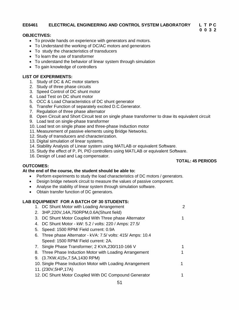
EE6461 ELECTRICAL ENGINEERING AND CONTROL SYSTEM LABORATORY L T P C 0 0 3 2
OBJECTIVES:
To provide hands on experience with generators and motors.
To Understand the working of DC/AC motors and generators
To study the characteristics of transducers
To learn the use of transformer
To understand the behavior of linear system through simulation
To gain knowledge of controllers LIST OF EXPERIMENTS:
1. Study of DC & AC motor starters 2. Study of three phase circuits 3. Speed Control of DC shunt motor 4. Load Test on DC shunt motor 5. OCC & Load Characteristics of DC shunt generator 6. Transfer Function of separately excited D.C.Generator. 7. Regulation of three phase alternator 8. Open Circuit and Short Circuit test on single phase transformer to draw its equivalent circuit 9. Load test on single-phase transformer 10. Load test on single phase and three-phase Induction motor 11. Measurement of passive elements using Bridge Networks. 12. Study of transducers and characterization. 13. Digital simulation of linear systems. 14. Stability Analysis of Linear system using MATLAB or equivalent Software. 15. Study the effect of P, PI, PID controllers using MATLAB or equivalent Software. 16. Design of Lead and Lag compensator.
TOTAL: 45 PERIODS OUTCOMES: At the end of the course, the student should be able to:
Perform experiments to study the load characteristics of DC motors / generators.
Design bridge network circuit to measure the values of passive component.
Analyse the stability of linear system through simulation software.
Obtain transfer function of DC generators.
LAB EQUIPMENT FOR A BATCH OF 30 STUDENTS: 1. DC Shunt Motor with Loading Arrangement 2
2. 3HP,220V,14A,750RPM,0.6A(Shunt field)
3. DC Shunt Motor Coupled With Three phase Alternator 1
4. DC Shunt Motor - kW: 5.2 / volts: 220 / Amps: 27.5/
UNIT II WAVEFORM CODING 9 Prediction filtering and DPCM - Delta Modulation - ADPCM & ADM principles-Linear Predictive Coding
UNIT III BASEBAND TRANSMISSION 9 Properties of Line codes- Power Spectral Density of Unipolar / Polar RZ & NRZ – Bipolar NRZ - Manchester- ISI – Nyquist criterion for distortionless transmission – Pulse shaping – Correlative coding - Mary schemes – Eye pattern - Equalization
51
EE6461 ELECTRICAL ENGINEERING AND CONTROL SYSTEM LABORATORY L T P C 0 0 3 2
OBJECTIVES:
To provide hands on experience with generators and motors.
To Understand the working of DC/AC motors and generators
To study the characteristics of transducers
To learn the use of transformer
To understand the behavior of linear system through simulation
To gain knowledge of controllers LIST OF EXPERIMENTS:
1. Study of DC & AC motor starters 2. Study of three phase circuits 3. Speed Control of DC shunt motor 4. Load Test on DC shunt motor 5. OCC & Load Characteristics of DC shunt generator 6. Transfer Function of separately excited D.C.Generator. 7. Regulation of three phase alternator 8. Open Circuit and Short Circuit test on single phase transformer to draw its equivalent circuit 9. Load test on single-phase transformer 10. Load test on single phase and three-phase Induction motor 11. Measurement of passive elements using Bridge Networks. 12. Study of transducers and characterization. 13. Digital simulation of linear systems. 14. Stability Analysis of Linear system using MATLAB or equivalent Software. 15. Study the effect of P, PI, PID controllers using MATLAB or equivalent Software. 16. Design of Lead and Lag compensator.
TOTAL: 45 PERIODS OUTCOMES: At the end of the course, the student should be able to:
Perform experiments to study the load characteristics of DC motors / generators.
Design bridge network circuit to measure the values of passive component.
Analyse the stability of linear system through simulation software.
Obtain transfer function of DC generators.
LAB EQUIPMENT FOR A BATCH OF 30 STUDENTS: 1. DC Shunt Motor with Loading Arrangement 2
2. 3HP,220V,14A,750RPM,0.6A(Shunt field)
3. DC Shunt Motor Coupled With Three phase Alternator 1
4. DC Shunt Motor - kW: 5.2 / volts: 220 / Amps: 27.5/