94
i Senior Design I Document December 2, 2013 Game Qube Group 33 Stephen Monn Matthew Dworkin Omar Alami University of Central Florida Dr. Samuel Richie Senior Design I

i
Senior Design I Document December 2, 2013
Game Qube
Group 33
Stephen Monn
Matthew Dworkin
Omar Alami
University of Central Florida
Dr. Samuel Richie
Senior Design I

ii
Table of Contents 1.0 Executive Summary 1
2.0 Project Description 3
2.1 Project Motivation 3
2.2 Goals and Objectives 4
2.3 Project Requirements and Specifications 5
3.0 Research Related to Project Definition 6
3.1 Existing Similar Projects and Products 6
3.1.1 Multi-Functional Hexahedron 6
3.1.2 How Not to Engineer: RGB LED Cube 8
3.1.3 Dynamic Animation Cube II 8
3.1.4 Kevin Darrah 8x8x8 RGB LED Cube 9
3.2 Relevant Technologies 11
3.2.1 Pulse Width Modulation (PWM) 11
3.2.2 Serial Peripheral Interface Bus (SPI) 11
3.2.3 Universal asynchronous receiver/transmitter (UART) 12
3.2.4 Persistence of Vision Display 13
3.2.5 Bluetooth 14
3.3 Strategic Components 15
3.3.1 Light Emitting Diodes (LEDs) 15
3.3.1.1 Round 5mm RGB LEDs 16
3.3.1.2 Square RGB LEDs 16
3.3.1.3 Multi-Color Flashing LEDs 17
3.3.1.4 Single Color LEDs 17
3.3.2 Micro-Controllers 18
3.3.2.1 MSP430 18
3.3.2.2 Main Microcontroller 20
3.3.3 Registers 23
3.3.3.1 74HC595 8-bit Shift Register/Latch 23
3.3.3.2 FIFO Registers 24
3.3.4 Integrated Circuits (ICs) 25
3.3.4.1 TLC5940 LED Driver with PWM 25
3.3.4.2 STP16CP05 LED Driver 26
3.3.4.3 AS7C3256A-10TCN SRAM 26
3.3.5 Transistors/Resistors/Capacitors 27
3.3.5.1 High Current NPN Transistor 28
3.3.6 Bluetooth and Controller 28
3.3.7 Power Supply 31
3.4 Possible Architectures and Related Diagrams 35
3.4.1 8-bit Color Encoding Schemes 35
3.4.1.1 RGB Encoding 35
3.4.1.2 HSL and HSV Encoding 36
3.4.2 Volumetric Display Construction 37

iii
3.4.2.1 Common Anode per Layer 37
3.4.2.2 Complete LED Addressing 38
3.4.3 LED Control 39
3.4.3.1 Shift Registers with Latch 40
3.4.3.2 LED Driver with PWM 41
3.4.3.3 Shared Memory Buffer 42
3.4.3.4 RGB Color Division 43
4.0 Project Hardware and Software Design Details 44
4.1 Overall Design Architectures and Related Diagrams 44
4.2 Input Design 45
4.3 LED Cube Design 49
4.3.1 LED Assembly 49
4.3.2 LED Control 51
4.4 Microcontroller Design 53
4.5 Power Design 56
4.6 Housing Design 58
4.7 Software Design 60
4.7.1 Virtual Environment 61
4.7.2 Arduino Software 63
4.7.3 Microcontroller Software 65
4.7.4 Animations and Games 65
5.0 Design Summary of Hardware and Software 68
5.1 Parts List 68
5.2 Hardware Design Summary 69
5.3 Software Design Summary 71
5.4 Design Issues 74
6.0 Project Prototype Construction and Coding 76
6.1 Parts Selection and Acquisition 76
6.2 PCB Vendor and Assembly 76
6.3 Final Coding Plan 77
7.0 Project Prototype Testing 80
7.1 Hardware Test Environment 80
7.2 Hardware Specific Testing 80
7.3 Software Test Environment 82
7.4 Software Specific Testing 82
8.0 Administrative Content 85
8.1 Milestone Discussion 85
8.2 Budget and Finance Discussion 87
9.0 Conclusion 90
Appendices A
Appendix A: Copyright Permissions A

1
1.0 Executive Summary
The Game Qube consists of an LED volume display cube that a person can play simple games on using a Bluetooth controller. Past LED cube project creations have mainly focused on showing pre-defined animations. This project intends to further those ideas so that a user will be able to control what is shown on the cube in the same way that a video game player has control over his character. Other than basic animations, playable game such as Pong and Snake will be implemented.
This project was chosen by a group of three computer engineers at UCF to be a good mix of hardware and software in which the whole group could experience a full engineering development project. Many project ideas were considered, all were somehow linked around some sort of interactive game. LED cube projects are common and have been done by UCF groups in the past; this project looks to stand out by becoming an interactive game system which a user has direct control over. Not only does an LED Cube require significant hardware design but the project will also go beyond traditional LED Cube projects to contain a large software design portion.
The main goal of the project is to allow a player to play a classic game in a brand new way by playing it in a 3D environment on an LED cube. In order to accomplish this, the cube needs to be large enough to house the number of LEDs necessary to replicate the intended game but small enough so that it is portable. Each LED in the display will be able to be one of eight different color combinations. With respect to the system required to make the cube function, it will include a microcontroller, LED control software, and an input device that will act as a controller for the game’s player. Several different control possibilities have been considered including the utilization of a small infrared camera of a Wii Remote to track the positioning of the player’s controller so he/she can point to a specific location in a three dimensional array of LEDs. The first attempt at control will be a simple Bluetooth controller. Finally, the system will be powered by a standard AC wall outlet and the cube will be connected to a control device utilizing LEDs with a common cathode. When completed, the LED cube system should be portable and easy to use for anyone who might want to use it regardless of knowing the internal workings. The final design will encapsulated in an acrylic casing to project the cube which will lay on top of a wood containment holding the electronic components. All that would be needed to play would be an outlet to plug into and the controller.
This project requires knowledge of both hardware and software design. In order to complete the physical LED cube display, the physical structure of the LEDs, the logical control over them, and the interface to the display must be designed from the ground up. The software includes designing unique games that work in a 3D space as well as low level software interfaces for input purposes and a small operating system to choose between the different applications and games.
2
The software design will also involve designing a custom rendering pipeline, as well as the software interface to output to the custom LED display. Other considerations for this project include integration of LCD screens rather than LEDs. Using a physical cube with at least three LCDs and head tracking software could emulate 3D objects using perspective and allow interaction and games to be made. However, the main constraint for this idea is expense of the LCD screens and the need of an external computer to provide the rendering capabilities.
To reach the goals of this project, the team has completed research on all the necessary components. Being a three member group, utilization of time and resources is a major emphasis. Depending on each member’s school and work schedules, some parts will progress faster than others. To ensure completion of all aspects of the project, modularity is a very large part of our design. This goal includes having the hardware, software, and control aspects of the design to be as independent as possible before integration is required. After gathering the basic requirements of each phase’s integration with the others, the development should be able to progress unimpeded for each individual phase. This allows the project to be divided into three development phases with an admin in charge of one. To reach such a goal, the research and communication of each phase must be very thorough, as developing one phase without proper research on its integration could prove detrimental.
The contents of this document will document in detail all the research of all aspects of the project that lead into the projects initial design that should allow the team to successfully begin construction and development of the LED cube.
3
2.0 Project Description
2.1 Project Motivation
Consisting of three computer engineers, the team looked at many options that utilized a good balance of hardware and software design. Rather than trying to find an idea that would allow sponsorship, the main motivation was a project that the team would all enjoy doing. Research for project ideas included looking at past UCF senior design projects, looking at other universities’ senior design projects, and other popular projects online. After discovering the LED cube project on instructables, the project’s interest was drawn. From there the team evaluated the pros and cons of the project, alternative ideas, and ways to separate this project from other similar projects.
Many other ideas involving a cube were considered, such as the LCD cube idea discussed earlier. The LCB cube would allow for full graphical rendering using LCD screens. Rather than being physical 3D screen like the LED Cube, the LCD cube would create the 3D illusion using multiple screens. The minimum needed would be three screens; each would display the perspective of the same scene creating a 3D illusion. TO create this, head tracking would be needed. This project would allow for many sorts of games and effects to display based on movement. While this project was very interesting the constraints proved too great. At least three five inch LCD displays would be needed, which are expensive, along with LCD drivers. To render the scene the project would require a full GPU inside a PC, which would not be a convenient project to demonstrate. The LED cube proved to be the best choice. Not only did it seem to have significant hardware, consisting of 1000 LEDs that need to be wired and configured in a custom designed electrical circuit, but also required high level programming to provide interactive features. The software and input side also allowed the project to become extendable. Depending on time constraints, more animations, games, and software features can be continually added to the project. The input, which would be at a minimum a Bluetooth control, could also be expanded to a more interactive IR movement controller and/or motion controls using accelerometers and gyroscopes.
Although the team decided a project like this would be enjoyable and motivating to work on, other considerations such as financing had to be considered. Without any significant energy or AI features, an LED cube project would most likely need to be self-financed. When considering all project ideas, the budget played a major factor. The goal was to find a project that could be financed with each member paying around $100. Based on rough estimates, the LED cube seemed to fit into this budget. Given all considerations the team was willing to spend some more if the project exceeded this budget. In the end, the LED cube was determined to be the best fit for the team in terms of scope, budget, and preference.

4
2.2 Goals and Objectives
The main goal of the project is to have a fully portable and encased 10x10x10 LED cube display that can be plugged into a wall and utilize a controller to turn on several animations and/or effects along with playing interactive games. The hardware goals include having the 10x10x10 LED array standing straight and stable. Not only did we want the LEDs to be aligned and straight, but the connecting wires should be as discreet as possible. The space between each LED is also very important, as it plays a main factor into viewing depth and LED ghosting. This goal also includes have a good design in which a minimum amount of wires are used in order to reduce space. Another hardware goal is to have as few circuit boards as possible, ideally one integrated circuit that can fit inside the casing and includes the LED cube circuitry, the microcontrollers, and the Bluetooth module. The encasing should be sturdy to carry and protect the cube, along with being transparent to see the cube and cause as little light reflection interference as possible.
The main microcontroller will connect the hardware and software. Our goal for the microcontroller includes a simple interface to control the LED Cube using only input and output pins. This is also true for the Bluetooth module, which will be controlled either only using transmit/receive pins, SPI, or using a Bluetooth adapter. The microcontroller will host all the software, thus the goal for the microcontroller includes support for a good IDE, preferably with C/C++. The goal for the input is develop a working Bluetooth control that can interact with microcontroller easily. This goal will allow the project to be expanded into more complex and interactive ways to control a 3D display.
The project design will be split into three general blocks. The first block is LED cube, which includes the 10x10x10 LED build and the integrated circuit that controls the columns and layers of the cube. The second block is the hardware/software integration which includes the microcontroller and the high level software. The final block is the control, which includes a Bluetooth receiver and any needed circuitry to communicate with the microcontroller. Additionally, other aspects of the design include the power and/or power supply, along with the acrylic and wood housing unit for the cube.
The goal is allow each member to be in charge of each block, allowing each block of the project to develop at each member’s comfortable pace, without impacting the other blocks. The reasoning behind this goal is allowing each member to utilize their skills most efficiently, and to allow the project to be expanded/changed in the future without requiring a complete overhaul. Knowing that the initial design will most likely need to be heavily modified, keeping each block modular allows changes to have a smaller impact. To accomplish this goal, the integration and communication of a block with one another is a high priority. Getting the integration design details correct in the initial design will prove to benefit the overall project during the development phase.
5
2.3 Project Requirements and Specifications
This project consists of a 10x10x10 hardware cube with corresponding circuitry, acrylic casing to cover and protect the cube, and an encased base to the host the electronics. The goal is to have the final product easily moveable and to be usable anywhere near a power outlet. Hardware requirements and specifications include: Hardware requirements include:
● Pixel Resolution: 10 x 10 x 10 = 1000 LEDs ● LED Volume Dimension: 10’’x10’’x10’’ ● Base Dimension: 12’’x12’’x4’’ ● Visible Sides of Cube: Top, All Sides (not Bottom) ● Cube Material: Acrylic, Wood ● LED Color: Multiple colors supported ● LED Refresh Rate: 60Hz ● Microcontroller: minimum 8 pin I/O ports, serial communication, 16MHz
clock speed, 512 KBytes Flash memory, C/C++ software support ● Color Depth: 8bit ● Operating Temperature: 10-30 Degrees Celsius ● Input Voltage: 120V AC at 60Hz (Standard Wall Outlet) ● Input: Bluetooth controller
Software requirements include: ● Developed in C/C++ ● Final code should be less than 512 KBytes ● Games and animations code should hardware and environment
independent ● A accurate and reliable simulation software environment should be
developed to allow for immediate testing and simulating of the games and animations
● Have a minimum of three selectable classic games to play ● Have at least one custom 3D specific game developed ● Have multiple animations selectable, interactive animations as well ● Bluetooth code to support Wii remote control
6
3.0 Research Related to Project Definition
3.1 Existing Similar Projects and Products
The LED cube project is a very popular do-it-yourself project. With the growth of communities like instructables, teams and individuals around the world have taken up fun projects that can be done with minimum resources. The LED cube projects high popularity is due to mix of both hardware and software design, along with being a cool expansion to the average engineers first circuit: powering a single LED. Ranging from 3x3x3 to 16x16x16 and beyond, LED cubes are fun but challenging project that allows a lot of design freedom. Hundreds of different hardware and software designs are possible, yet they all come down to the same basic concepts which are detailed in the initial research section. Several different colored/uncolored, square/round, diffused/undiffused choices are available for LEDs alone. Circuits can utilize endless combinations of multiplexing, shifting, and LED drivers to control the LEDs. Software can range from simple animations to anything you can think of within a 10x10x10 display. Controls can range from none, to accelerometers and controllers. Designs from UCF include several LED cube projects each with its own twist of functionality and design. The Game Qube will attempt to separate itself utilizing the interaction of a user playing a game. A basic template of how an LED cube works and looks can be seen in the very popular Instructables 8x8x8 cube. This standard implementation that includes a single color LED 8x8x8, microcontroller powered cube that plays animations. Different implementations of this standard idea are discussed in the following sections.
3.1.1 Multi-Functional Hexahedron
The Multi-Functional Hexahedron was an LED cube project by UCF Group 5 in Spring/Summer 2013. Their goal was also to provide an interactive LED Cube. Instead of having a controller or interactive games, they implemented features such as accelerometer control and VU meter control. Utilizing RGB LEDs the cube not only plays standard animations but can also be used in accelerometer mode which allows the LEDs to change with the cubes movement. The VU meter mode allows the cube to function as a 3D music visualizer, changing the LEDs based on the changes of music.
The cube would run in three different modes: animation mode, VU mode, and accelerometer mode. In animation mode, animations cycle through various pre-programmed animations. The animations include different effects such as lighting the cube in a diffused manner and quickly cycling through each of the layers. VU mode was a simulation of a music equalizer seen on computers, being implemented on the 3D LED cube. The VU meter was able to read different types of signals received from the input and communicate them to the microcontroller, which would then light the cube in a corresponding pattern. The VU meter was controlled by regular 8mm headphone jack, which could have a smartphone or

7
other audio device play music and show the effects on the cube. In accelerometer mode the LED cube was able to light up and react depending on how it was moved. This included a water feature which had the cube working as if was filled with water and change the lighting of the cube depending on how it was tilted. To allow for this interaction, the housing had to be of a good size and weight.
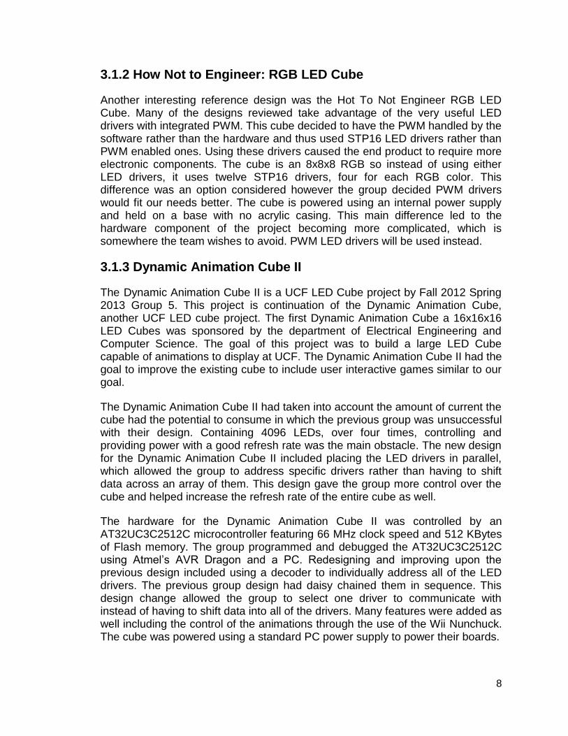
The hardware design included LED drivers and an ATxmega64 microcontroller which used an SPI converter to connect to a PC for programming. To support the various modes, a VU meter chip and +-5g accelerometer chip was used. To power the cube a combination of wall and USB power was used. They had a USB connector mount to the PCB which allowed them to power the cube from a PC or wall wart with a USB port. The final housing was encased in acrylic panels, allowing the protection and viewing of the LED cube and hardware underneath show in Figure 3.1 below.
The software was written in C/C++ using the Atmel Studio 6 development platform for the ATxmega64 programming. While the cube is powered on, it runs in a loop checking which of the three modes to run in. The main function would choose the appropriate mode and switch between them. Overall, the final product looks very nice as shown below in Figure 3.1. The main takeaway from this project was the good presentation which the group would like to emulate with a similar looking presentation for the final project. Acrylic will likely be used as well, but with a larger base made of wood or a similar material.
Figure 3.1: The Multi-Functional Hexahedron
Permission Requested and Pending1
8
3.1.2 How Not to Engineer: RGB LED Cube
Another interesting reference design was the Hot To Not Engineer RGB LED Cube. Many of the designs reviewed take advantage of the very useful LED drivers with integrated PWM. This cube decided to have the PWM handled by the software rather than the hardware and thus used STP16 LED drivers rather than PWM enabled ones. Using these drivers caused the end product to require more electronic components. The cube is an 8x8x8 RGB so instead of using either LED drivers, it uses twelve STP16 drivers, four for each RGB color. This difference was an option considered however the group decided PWM drivers would fit our needs better. The cube is powered using an internal power supply and held on a base with no acrylic casing. This main difference led to the hardware component of the project becoming more complicated, which is somewhere the team wishes to avoid. PWM LED drivers will be used instead.
3.1.3 Dynamic Animation Cube II
The Dynamic Animation Cube II is a UCF LED Cube project by Fall 2012 Spring 2013 Group 5. This project is continuation of the Dynamic Animation Cube, another UCF LED cube project. The first Dynamic Animation Cube a 16x16x16 LED Cubes was sponsored by the department of Electrical Engineering and Computer Science. The goal of this project was to build a large LED Cube capable of animations to display at UCF. The Dynamic Animation Cube II had the goal to improve the existing cube to include user interactive games similar to our goal.
The Dynamic Animation Cube II had taken into account the amount of current the cube had the potential to consume in which the previous group was unsuccessful with their design. Containing 4096 LEDs, over four times, controlling and providing power with a good refresh rate was the main obstacle. The new design for the Dynamic Animation Cube II included placing the LED drivers in parallel, which allowed the group to address specific drivers rather than having to shift data across an array of them. This design gave the group more control over the cube and helped increase the refresh rate of the entire cube as well.
The hardware for the Dynamic Animation Cube II was controlled by an AT32UC3C2512C microcontroller featuring 66 MHz clock speed and 512 KBytes of Flash memory. The group programmed and debugged the AT32UC3C2512C using Atmel’s AVR Dragon and a PC. Redesigning and improving upon the previous design included using a decoder to individually address all of the LED drivers. The previous group design had daisy chained them in sequence. This design change allowed the group to select one driver to communicate with instead of having to shift data into all of the drivers. Many features were added as well including the control of the animations through the use of the Wii Nunchuck. The cube was powered using a standard PC power supply to power their boards.
9
The software used for the cube was written in C utilizing Atmel development tools and software framework. The group had programmed the software to run in a state machine. The states include one state for each of four games, a lobby, an ambient state, and an instance of Conway’s Game of Life. To control the states the user input from a Nunchuck controller was used. The software was configured to have a refresh rate of around 90 Hz. To communicate with the cube, Serial Peripheral Interface was implemented.
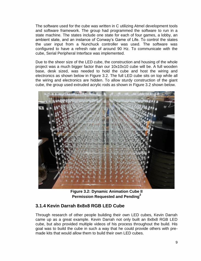
Due to the sheer size of the LED cube, the construction and housing of the whole project was a much bigger factor than our 10x10x10 cube will be. A full wooden base, desk sized, was needed to hold the cube and host the wiring and electronics as shown below in Figure 3.2. The full LED cube sits on top while all the wiring and electronics are hidden. To allow sturdy construction of the giant cube, the group used extruded acrylic rods as shown in Figure 3.2 shown below.
Figure 3.2: Dynamic Animation Cube II
Permission Requested and Pending2
3.1.4 Kevin Darrah 8x8x8 RGB LED Cube
Through research of other people building their own LED cubes, Kevin Darrah came up as a great example. Kevin Darrah not only built an 8x8x8 RGB LED cube, but also provided multiple videos of his process throughout the build. His goal was to build the cube in such a way that he could provide others with pre-made kits that would allow them to build their own LED cubes.
10
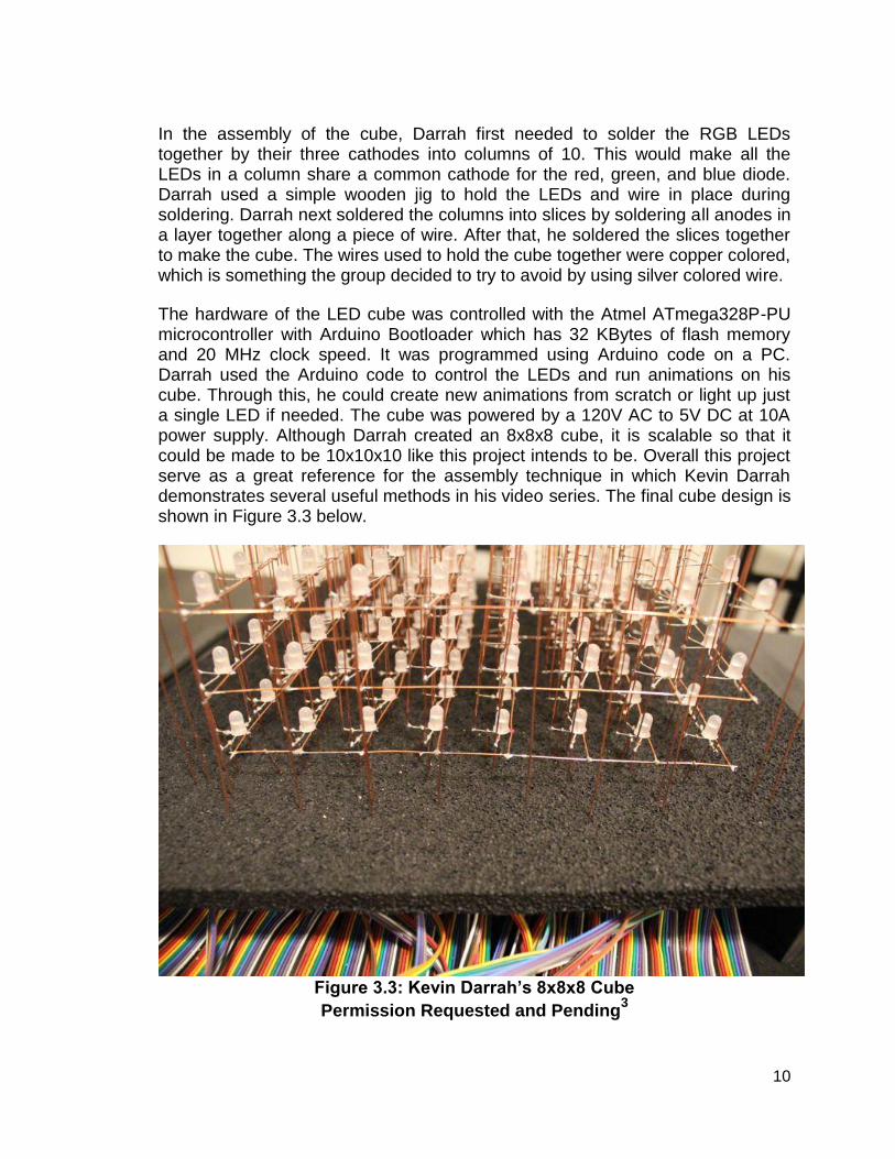
In the assembly of the cube, Darrah first needed to solder the RGB LEDs together by their three cathodes into columns of 10. This would make all the LEDs in a column share a common cathode for the red, green, and blue diode. Darrah used a simple wooden jig to hold the LEDs and wire in place during soldering. Darrah next soldered the columns into slices by soldering all anodes in a layer together along a piece of wire. After that, he soldered the slices together to make the cube. The wires used to hold the cube together were copper colored, which is something the group decided to try to avoid by using silver colored wire.
The hardware of the LED cube was controlled with the Atmel ATmega328P-PU microcontroller with Arduino Bootloader which has 32 KBytes of flash memory and 20 MHz clock speed. It was programmed using Arduino code on a PC. Darrah used the Arduino code to control the LEDs and run animations on his cube. Through this, he could create new animations from scratch or light up just a single LED if needed. The cube was powered by a 120V AC to 5V DC at 10A power supply. Although Darrah created an 8x8x8 cube, it is scalable so that it could be made to be 10x10x10 like this project intends to be. Overall this project serve as a great reference for the assembly technique in which Kevin Darrah demonstrates several useful methods in his video series. The final cube design is shown in Figure 3.3 below.
Figure 3.3: Kevin Darrah’s 8x8x8 Cube
Permission Requested and Pending3
11
3.2 Relevant Technologies
3.2.1 Pulse Width Modulation (PWM)
One of the major difficulties this project involves is how to adjust the brightness of each LED. The brightness of each LED is determined by current passing through it. The direct approach would be to vary the resistance or voltage of the circuit to get a current resulting in the desired brightness. However, this is very impractical for this project since we will need the brightness to be able to be controlled and varied over time. A better solution to the problem for this project is a method called Pulse Width Modulation.
The basic concept of Pulse Width Modulation involves providing a constant current to the LED, and then pulsing the current through time to create the illusion of a lower brightness. For example, if the LED is pulsed with a constant current so that there is only current flowing at an average of half the time, then the LED will only appear to be half as bright as if there was the same current level flowing at all time. Of course, this pulsing of the current must occur at a very high frequency or else the blinking will become noticeable to the human eye, effectively ruining the illusion of a lower brightness and instead provide a simple blinking effect. The Duty Cycle of the pulse is defined as the percentage of time there is current flowing through the LED. By varying the Duty Cycle on the LED, we can effectively vary how bright the LED will be.
In summary, the reason this technology is utilized in the final overall design is it provides a way of adjusting the brightness of an LED without having to modulate the circuit’s resistance or input voltage, which would require a significantly more complex circuit design.
3.2.2 Serial Peripheral Interface Bus (SPI)
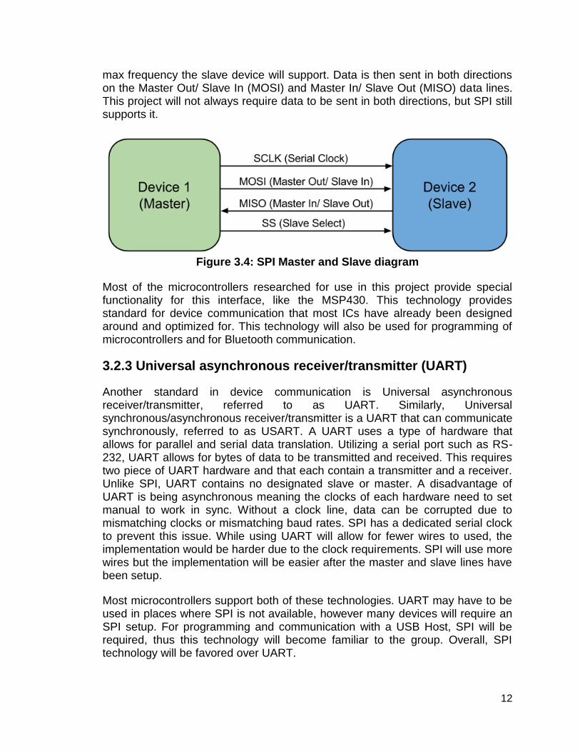
This project includes many different kinds of devices doing their own individual tasks in order to split down the work into manageable pieces. Because there will be several unique devices like this, this project will involve the need for these devices to communicate with each other. One of the standards in device communication for problems such as this is the Serial Peripheral Interface, also referred to as SPI.
The Serial Peripheral Interface was first developed by Motorola and is a synchronous serial communication between a master device and a slave device. The interface is also commonly known as the Four Wire Serial Bus, since it uses mainly just four wires. The wires, or connections, are the Serial Clock, Master Out/ Slave In, Master In/ Slave Out, and Slave Select. Multiple Slave Select lines on the master also allow for communication between more than one slave devices as shown in Figure 3.4 below. The communication process starts with the master setting the Serial Clock to have a frequency less than or equal to the
12
max frequency the slave device will support. Data is then sent in both directions on the Master Out/ Slave In (MOSI) and Master In/ Slave Out (MISO) data lines. This project will not always require data to be sent in both directions, but SPI still supports it.
Figure 3.4: SPI Master and Slave diagram
Most of the microcontrollers researched for use in this project provide special functionality for this interface, like the MSP430. This technology provides standard for device communication that most ICs have already been designed around and optimized for. This technology will also be used for programming of microcontrollers and for Bluetooth communication.
3.2.3 Universal asynchronous receiver/transmitter (UART)
Another standard in device communication is Universal asynchronous receiver/transmitter, referred to as UART. Similarly, Universal synchronous/asynchronous receiver/transmitter is a UART that can communicate synchronously, referred to as USART. A UART uses a type of hardware that allows for parallel and serial data translation. Utilizing a serial port such as RS-232, UART allows for bytes of data to be transmitted and received. This requires two piece of UART hardware and that each contain a transmitter and a receiver. Unlike SPI, UART contains no designated slave or master. A disadvantage of UART is being asynchronous meaning the clocks of each hardware need to set manual to work in sync. Without a clock line, data can be corrupted due to mismatching clocks or mismatching baud rates. SPI has a dedicated serial clock to prevent this issue. While using UART will allow for fewer wires to used, the implementation would be harder due to the clock requirements. SPI will use more wires but the implementation will be easier after the master and slave lines have been setup.
Most microcontrollers support both of these technologies. UART may have to be used in places where SPI is not available, however many devices will require an SPI setup. For programming and communication with a USB Host, SPI will be required, thus this technology will become familiar to the group. Overall, SPI technology will be favored over UART.

13
3.2.4 Persistence of Vision Display
One of the specifications of this project is a cube display with pixel dimensions of 10x10x10. This brings many challenges, but perhaps one of the biggest is how to wire up all one-thousand LEDs so that they can be individually controlled. This is not even mentioning the fact the RGB LEDs will require 3 lines to appropriately control the color. The straight forward approach would be to connect individual wires to each LED. However, this approach is not very practical since that many wires will become very messy and reduce the visibility of LEDs towards the back of the cube that may be blocked by wires. This would also require the states of all LEDs to be controlled directly by the I/O of some micro controller. To reduce this overwhelming load of LED control, the phenomenon of Persistence of Vision can be used. Not only will the visibility be affected by physical LEDs and wires, but the reflection and ghosting of the LEDs onto each other will also affect the visibility.
Persistence of Vision directly refers to the way in which the human eye works. The human eye can easily recognize an object blinking if it’s at a small frequency (around 5-10Hz). However when the blinking is sped up to much higher frequency, the human eye cannot keep up, and the perceived image is a constant sort of mixture of the on and off state. The reason for this mostly lies in the phenomenon that images stick around on the human retina for a few fractions of a second before the image is lost. So when something flickers off for periods of time smaller than this decay, the image never appears, to the human eye, to have flickered at all.
Despite all the good, there is also a very important factor that should not be overlooked when determining the number of LEDs to be on at any given time. Although there are many benefits from multiplexing the LEDs, like a reduction in needed I/O, overall brightness of the LEDs will be reduced. If an LED is only on one tenth of the time, it will appear to be ten times less bright. This is not an unsolvable problem though, as the current can simply be increased until that one tenth brightness is suitable for the display. The problem however, comes into play when this current starts to break the max current allowed by the LED driver. By multiplexing the cube into layers of ten, the max current (in terms of the appearance of brightness) is effectively cut down by a factor of ten. Many options are available to adjust the brightness of the LEDs
Overall, the advantage of this technology is that we can cut the control load down by a factor of ten if we only light up one tenth of the cube at a time. By cycling through and lighting up all ten sections individually, but at a very high frequency, the human eye will perceive the entire cube to be on at the same time. Now the load of all the control is split up over time, which makes the problem much easier to tackle. This also allows for a reduction in the total amount of wires needed, since all ten sections can be tied together with a separate control piece sending power to only one of the sections.
14
3.2.5 Bluetooth
One of the challenges of creating this playable LED cube is in determining how it will be controlled. Options considered included wired controllers, wireless controllers, built-in arcade style controls, motion controls, and camera viewing controls. The team wanted to have the user be able to control the cube wirelessly, where the input device communicates directly with the microcontroller. The team decided that the best way to solve this problem was to utilize Bluetooth in the design.
The basic idea of Bluetooth is that data can be transferred wirelessly between devices within a certain range through the use of wave radio technology. The range can reach up to 100 meters depending on the specific device. The range desired is at least five feet away from the cube in all directions. Each device needs to have its own Bluetooth chip in order for communication between them to occur. For the purposes of this project, the input device that will be attempted to use, a Nintendo Wii remote, already has built-in Bluetooth capabilities. Other Bluetooth enabled devices such as mice, keyboards, and other generic game controllers can be used in the future.
Many Bluetooth forms were considered for this project. Simple Bluetooth modules were the first to be considered. In choosing a Bluetooth chip to use with the microcontroller, it is necessary to understand what is compatible with the Bluetooth type found in a Wii remote. Wii remotes use the HID profile (Human Interface Device) of Bluetooth, which allows for user input and is common in many input devices such as controllers and keyboards. Therefore, if the project utilizes Bluetooth chips it would need the microcontroller’s Bluetooth chip to support the HID profile in order to receive signals from the Wii remote.
Many microcontrollers have hardware that allows for simple Bluetooth connections; however this will not be sufficient for the needs of the project. Also this would add another constraint in picking the microcontroller which would not be necessary. The final consideration for establishing Bluetooth connections was using a Bluetooth dongle and a USB host. A USB Bluetooth dongle can be used to connect Bluetooth devices to the USB host. The USB host will allow the dongle to communicate an active Bluetooth connection to the microcontroller. A USB host module would use SPI to communicate with the microcontroller, and the Bluetooth module would communicate with the Bluetooth controller through the USB host.
Many choices are available to utilize Bluetooth technology, each with pros and cons. In the end, this technology is very desirable to include in the final design because it will allow the user’s input device and the microcontroller to communicate with the input wirelessly and easily without the use of connecting wires.

15
3.3 Strategic Components
3.3.1 Light Emitting Diodes (LEDs)
The volumetric display described in the specifications of this project will obviously require some sort of light technology to create images. The most obvious solution to this is to use Light Emitting Diodes, since they consume much less power than other lighting technologies. By definition, they are just as the name indicates (a diode which emits light when a current is passed through it.) However, one possible downside is the cost, since the project specifications will require around one-thousand individual LEDs.
One important design aspect of all LEDs is clarity. Most LEDs are simply clear to allow light to pass through without being disrupted or scattered. However, for an LED providing multiple colors by combining a red, green and blue LED, it may be desirable to have the light scattered a bit in order to mix the three base colors in single noticeable color. Because of this, LEDs typically come in a clear or diffused design. The diffused design looks a little cloudy, but scatters and mixes light better, whereas the clear design simply lets the light pass straight through. The difference can be seen in Figure 3.5 below.
Figure 3.5: Clear (left) vs. Diffused RGB (right) Light Emitted Diodes
It is important to make sure that, when ordering any LEDs that they are rated at the current level we need and can provide the brightness level outlined in the projects specifications.

16
3.3.1.1 Round 5mm RGB LEDs
One of the more common shapes of LEDs is the round design as shown above in Figure 3.5. The advantage of this is that it provides a decent and consistent viewing angle from nearly all directions except the bottom view. However, for this project, a viewing angle from the bottom is not needed due to overall construction of the display mounted on a solid base. An RGB LED like this also provides capability to provide a full range of colors by mixing the light from a red, blue and green LED. Being able to provide multiple colors is also one of the specifications for this project.
Because this type of LED is actually composed of three separate LEDs in one, there are four leads sticking out at the base, instead of the typical two. The longest lead is a common anode or a common cathode. The remaining three leads consist of the anode/cathode of the individual red, green and blue colors. Providing different brightness’s to each of the color leads allow for the creating of a wide array of colors. The additional leads also account for why the LED is mostly only found with a 5mm diameter and not a 3mm diameter, which is also common among round LEDs. The additional leads require more space to fit, so a 3mm can almost never be found. In summary, this type of LED provides multiple colors that can be controlled by logic devices and provides a viewing angle well suited for a volumetric display that can be walked around as outlined in the projects specifications.
3.3.1.2 Square RGB LEDs
Another common design for RGB LEDs is a square shape which looks very different than the round LEDs. The base of the each square LED is square with a round dome on the top. Although the top is round, just like any other round LED, the sides are squarer and not designed to emit light as much as the top. These LEDs are most useful for projects with some sort of two dimensional display since they can be easily tiled together in a grid pattern. The square design also fits very nicely into the RGB design discussed in the round 5mm RGB LED section, in that the four leads can easily fit into one of the four corners. It is important to note that the leads on these LEDs are much shorter than the leads found on the round LEDs. This is an important factor to consider when designing the wiring of the large volumetric display. A lot of additional wire would need to be used to make up for the short leads reach. However, these LEDs are also very friendly to the prototyping environment, as their shape can be easily popped into place on a breadboard.
This type of LED provides multiple colors that can be controlled by logic devices just like the round RGB LED, but the viewing angle is not quite as good from the sides. The small, spaced out leads on the LED would also make it hard to construct a large cube design. Because of these reasons, this type of LED is not the best choice for this project.

17
3.3.1.3 Multi-Color Flashing LEDs
One of the requirements specified for this project is to be able to display multiple colors at any given location in the volumetric display. In order to do this, LEDs with multiple color possibilities need to be used. One option that meets this requirement is a round LED that flashes between the primary colors of red, green and blue. The main difference is the ability to flash multiple colors at once, rather than one RGB color. Unlike the round 5mm RGB LED option discussed above, this LED only has two leads and the colors are changed in a flashing pattern. These LEDs can be found in both a fast flashing design and a slow flashing design. This however, causes a problem when it comes to the controlling of the colors displayed.
The only way to really control the color would be to design a logic device that ran in sync with the flashing of the LED. The logic device would then use PWM to change the brightness of the LED. If the logic device uses a higher duty cycle when the LED is currently on red and then drops the duty cycle when the LED is any other color, the LED would appear to be only red. Through this technique a wide array of colors could be created. The downside to this is the major challenge of getting the logic device in sync and then staying in sync with the LEDs flashing. Each LED may have a slightly different flashing pattern and just the slightest variant can cause the illusion to fail entirely. However, with only two leads, the wiring of the actual cube would be much simpler, as well as less I/O pins will ultimately be needed.
Despite the easier wiring, the control over apparent color of the LED is just much too difficult to try and implement. This is especially so in this project since the final design will need one thousand LEDs to all be perfectly controlled and in sync.
3.3.1.4 Single Color LEDs
The most common LEDs are probably the simple one color round LED which look nearly identical to the round RGB LEDs. They can be found in both 3mm diameter and 5mm diameter. These simple diodes have only two leads (one cathode and one anode). The beneficial part of this simple design is that it does not require as much I/O to control as one of the RGB LEDs mentioned earlier, however there are a few things lost as a result of this simplification.
It’s important to note that in order to meet the color requirements outlined in the specifications for this project, multiple single color LEDs would need to exist at a single spot in order to generate a range of different color possibilities. While this is not impossible to do it is very impractical, since it would result in a very bulky display design. There would also be a problem in getting the colors to mesh together since they are not together in any sort of diffused enclosure. Having to use multiple single color LEDs in one spot would also negate the benefit gained

18
from the simple to lead interface. There would now be two leads per color desired to mix.
Despite the initial conceived simplicity, these simple LEDs do provide any practical way to display multiple colors even when trying to group them together, thus failing to meet the specifications for this project.
3.3.2 Micro-Controllers
For this project, there are many specifications that require complex logic computation and I/O control at high speeds. In order to meet the specifications, several microcontrollers should be implemented into the design. This includes microcontrollers for both the logic involved in running the volumetric display and running more complex computations for game logic and artificial intelligence. Important things to keep in mind while choosing an appropriate microcontroller are the power requirements, I/O capabilities and processing speed. It’s also important to keep in mind the fact that these devices will mostly like need to communicate with each other. Separate microcontrollers will be used for the LED logic circuit and main microcontroller board.
3.3.2.1 MSP430
For some of the less complicated computing and logic tasks in this project, a less powerful microcontroller can be utilized. This would allow for less power consumption compared to using a more powerful microcontroller for the smaller remedial tasks. A smaller microcontroller also usually means a smaller price tag which will lower the overall costs involved in this project. The MSP430 line of microcontrollers by Texas Instruments can accomplish just this. TI provides a convenient and affordable way to quickly use and program a simple microcontroller with the MSP430 Launchpad. This microcontroller is one the group is very familiar with and comfortable utilizing.
In particular, the logic and LED control of the volumetric display can benefit greatly from this small device. The MSP430 value line utilizes very low power consumption while running and also supports a sleep state that allows the chip to consume virtually no power when the chip is not in use. It’s because of this sleep state that the gains in power consumption will really be evident since the logic for the display will only need to be computed in small bursts at a time.
There are many different variations on the MSP430, but they all stem from the same 16 bit RISC type architecture. Factors that vary include ram size, flash size and number of I/O ports. These variations can be seen in Figure 3.6 below. All configurations will use the general software but the hardware will support different number of pins, different amount of memory, and different clock speeds.

19
Model RAM (kB) Flash (kB) Clock (MHz)
I/O Pins
MSP430g2553 0.5 16 16 24
MSP430g2203 0.25 2 16 24
MSP430g2303 0.25 4 16 24
MSP430f5529 8 128 25 63
Figure 3.6: MSP430 Model Differences
A few things to keep in mind while selecting between the different MSP430 varieties include amount of RAM, clock frequency and number of I/O pins. A large amount of RAM is required especially if the MSP430 will need to store the states of all LEDs in memory. The minimum amount of RAM in the case of this project would be 1000 bytes, or one byte per LED. The clock rate should also be closely looked at. A faster clock rate means the serial data transmission to the LED drivers can be performed at a faster rate. It’s also important to note the limitations of the LED drivers, since for example the TLC5940 has a max serial data input of 30 MHz. This means that the clock frequency of the chosen MSP430 should not exceed this maximum. Finally, the number of I/O ports is important when dealing with control over lots of devices. For example, any sort of external memory buffer will need I/O pins for the address and the data making a 16kB memory IC require a total of 22 pins. Then additionally even more pins would be required to control the LED Drivers, thus to be safe more pins would be good to have.
Another factor to consider with the MSP430 is the development tools that can easily be found for it and easily used. The group has experience using these tools which can help in the development. Texas Instruments provides an inexpensive development board called the Launchpad, which is aimed at helping small projects, get off the ground and running is a very short amount of time. There are also several free compilers and integrated development environments available to aid in programming these particular micro controllers (and also others like it). A compiler can be found in both assembly and C. The C compiler is a huge benefit due to a much higher level logic concept programming capability (more similar to human concepts of logic and not just a broken down set of instructions). TI Code Composer Studio allows for immediate and convenient C programming to the microcontroller. The MSP430 also has a very large and helpful support ecosystem, with resources to utilize if any questions should arise while trying to integrate the microcontroller into this project. In conclusion, the MSP430 provides a cheap, low power consumption and easy way to control some of the smaller logic aspects of this project. In particular, the MSP430f5529 covers all the needs of the project in terms of RAM, clock frequency and amount of I/O.

20
3.3.2.2 Main Microcontroller
The main microcontroller decision was very important for this project as it brings the hardware LED cube, the Bluetooth input, and the software together. The main factors into deciding on a microcontroller included the available memory, the input/output pins, and the speed. One of the goals for this project includes being able to play multiple animations and games. To allow the cube to play multiple animations and choose between several games, along with supporting a Bluetooth control, our microcontroller choice must support enough flash memory to store all the code.
Based on the research of other LED cube projects, most projects with 64 kilobytes of memory are able to store sufficient memory for several basic animations. Some projects like the Multi-Functional Hexahedron seemed to run into memory restrictions when adding additional features. To support all the animations this project plans to run on the cube, the decision was made to have at least 128 kilobytes of memory for animations alone. Based on our initial software design and emulation in our virtual cube environment, the code size to make an animation can be very efficient and redundant. Code size for games however, requires a lot more code to support AI and game logic. Thus the memory requirements for supporting full games and input control were estimated to be at least 256 kilobytes, giving a total memory estimation of 384 kilobytes. To be safe, all memory estimations were very generous, and because the most common next available increment from 384 kilobytes was 512, 512 kilobytes was deemed to the best available option. A large contributing factor to the memory requirements was the fact that most microcontroller specifications are only available at certain logic increments, while 384 kilobytes is available, it is much less common than 256 and 512. This trend also meant that microcontrollers with a low clock speed and low pin count also had relatively low memory. In the end, after evaluation each microcontroller requirement, the logical increment that fit our requirements the best was chosen.
The input and output requirements included the main output pins to the LED cube, and the input pins from the Bluetooth control if a UART design is chosen. Initial design deemed our output format from the microcontroller would be 10 bits per clock cycle, 1 bit per pin. For a possible Bluetooth module, 1 transmit pin and 1 receive pin are required along with power and ground. For Bluetooth using SPI and independent power, four SPI pins will be needed. This made the initial estimation to be 14 output pins assuming the microcontroller will only power the Bluetooth module directly at most, forcing the cube to get power directly from the power supply.
The clock cycle and bit size ended up being less important than were expected. Similar projects used 32-64 Mhz speeds for their microcontrollers, which based on the our hardware would be more than enough as our cube is believed to a refresh rate of about 16 Mhz. Based on the microcontrollers logical increments, any microcontroller with 256 kilobytes will usually have a clock cycle speed of at

21
least 32 Mhz. The bit size was heavily tied to the type of architecture the processor was. The group has experience using the TI MSP430, a 16-bit architecture, and although the team is comfortable and familiar developing with it, the team would also like to have experience using other hardware and tools. The manufacturer of the microcontroller is the main factor in the development tools that will be used for the project software. The MSP430 uses TI’s Code Composer, which the group has experience using and will be using to program our MSP430 controllers for the LED cube logic circuit. Thus, other manufacturers besides TI were favored for the main microcontroller decision. Some of the most prominent manufactures include Atmel, Cypress, and Microchip Technology. The main requirement when evaluating different manufacturers included the development environment. A goal for this project was to be able to directly program our microcontroller using a C/C++ IDE. Atmel microcontrollers seemed to be a very popular choice among our projects due to their C/C++ compiler, community support, and architecture choices. Atmel produces microcontrollers from two main architectures, ARM and AVR. Because the final software will be written in C/C++ the architecture was not a very important factor. Instead, each of these architectures was evaluated in their ability to store memory and save space. AVR architecture comes in both 8-bit and 32-bit, yet the 8-bit microcontrollers are only available with up to 384 KBytes of memory. ARM architecture is comes in 32-bit and 64-bit. The benefit of having fewer bits per instruction directly contributes to the how much space the code takes in memory, but at a cost of performance. For our purpose, the performance of a simple 8-bit processor would be sufficient; however the memory options are sparse.
Ultimately the decision came down to comparing the available options of Atmel microcontrollers of both AVR and ARM. Atmel produces the device family of 32-bit AVR UC3 with up to 512 KBytes of flash memory, 48-144 pins, and up to 66 MHz. These specifications meet all of the initial requirements and led to the first candidate, the AT32UC3B0512. Atmel’s ARM choices included the ARM Cortex family and the ARM7TDMI. Although both of these are 32-bit, ARM features Thumb and Thumb2 instruction sets to save space. The thumb is a 16-bit instruction set based on ARM32, allowing certain processors to run in this mode and save code size, but also results in reduced functionality at times. Thumb2 is variable length instruction set that came execute both 16 and 32-bit size instructions, allowing the best of both worlds of Thumb and ARM32. The ARM7 line of processors features Thumb mode along with ARM32, while ARM Cortex is available with Thumb2. Due to performance speed not being as important as the memory requirement, the ARM7 line seemed to be more appropriate due to reduced code size. After further research, the ARM Cortex line being more current has a stronger support community and easier development environment. Many of the ARM7 processors still require assembly code for initialization unless directly implemented by the IDE. This lead to the two ARM candidates for our microcontroller choice: AT91SAM7S512, an ARM7, and ATSAM3S8B, an ARM Cortex-M3. The features of all three initial microcontrollers’ possibilities are shown in Figure 3.7 below.

22
Model Family Architecture Flash (kB)
Clock I/O Pins
AT32UC3B0512 AVR UC3 32-bit AVR 512 64 60
AT91SAM7S512 ARM7 ARM32/Thumb 512 64 55
ATSAM3S8B Cortex-M3
Thumb2 512 64 64
Figure 3.7: Atmel Microcontroller Candidates
The final factor in choosing a microcontroller was the programming interface. To program the microcontroller it needs to be mounted on a board with the pins mapped and a serial port programmer that can connect to USB. Research led to the determination that AVR microcontrollers allowed the most freedom for programming. A very popular utility to program AVR microcontrollers is the AVRDude software. It allows for easy downloading of programs to the AVR ROM using in-system programming. The options for ARM microcontrollers are much smaller and require more expensive programmers. To utilize AVRDude, a compatible microcontroller and ISP programmer is all that is needed. Based on this information, an Atmel AVR microcontroller was favored. Based on the AVRDude supported microcontrollers, the AT32UC3A0512 was the only 512kB choice. The AT32UC3B0512 is not directly supported by AVRDude, but shares nearly identical specifications as the B0512. The main differences include the AT32UC3A0512 having 144 pins rather than 64 pins, meaning it still fits the requirements of our microcontroller. While it contains a lot more pins than are necessary, this microcontroller allows the project to complete the required tasks and be easily programmed.
The final board containing the microcontroller would require the pins to be mapped on a printed circuit board. This would lead to having the testing of the LED cube being delayed until the LED cube, LED logic circuit, and microcontroller board were all built. To allow the software and Bluetooth to begin development and testing, more convenient development tools will be used while the final design is being built. Development boards that replicate our microcontroller design will be used for initial software testing. Boards like this available include Arduino, Raspberry Pi, and Beagleboard. Beagleboards and Raspberry Pi both include very powerful hardware with features such as GPU hardware and HDMI output which extend outside the scope of our project. Arduino on the other hand, has many embedded microcontroller options. Arduino boards are open hardware embedded microcontroller boards with input/output pins mapped along with easily programmable interfaces of micro/mini USB. The boards are programmed using the Arduino IDE in C/C++ and include a large community of support. A popular choice for smaller cubes is the Arduino Uno; an ATmega328 powered, 32 kilobytes flash processor, which falls short of our initial requirements. This led to the team to the Arduino Due. The Arduino Due is

23
powered by an Atmel SAM3X8E ARM Cortex-M3 CPU. Comparing this to the initial microcontroller choices, it is a very strong match and almost identical to the ATSAM3S8B. The Due implementation of the SAM3X8E has 54 input/output and an 84 MHz clock versus the ATSAM3S8B’s 64 input/output and 64 MHz clock, both being more than enough. Other features of the Due included micro and mini USB port for programming and a power jack.
Overall, the Arduino Due, is almost an exact match to the project’s microcontroller design. The Arduino Due has 512 kilobytes memory and an integrated USB host to allow for a USB Bluetooth dongle. Thus, the Arduino Due proves to a very useful development tool to use while designing and building our microcontroller. A main theme that the team wanted to implement was to keep the project modular, allowing the hardware cube, microcontroller generated software, and Bluetooth input to be developed independently. The Arduino Due allows the team to immediately start developing the software with the help of the virtual environment software the team is utilizing.
The AT32UC3A0512 will be used as the project’s main microcontroller. The board to host this microcontroller will be a separate board to allow the project to remain modular. The board will map the necessary pins to both the LED circuit and the Bluetooth host. The AT32UC3A0512 fits all of the initial microcontroller requirements: memory, input/output, speed, and C/C++ development environment, making it a good choice as the main microcontroller.
3.3.3 Registers
This project will involve many different types of logic devices and small logic circuits. One of the necessities that come out of designing such circuits and interfaces is a way to remember certain logic states. A register allows for small memory storage that is useful in many logic circuits. This will help tremendously in this project for many aspects such as keeping track of any large buffers that may be used for the volumetric display.
There are many different types of registers with different interfaces, despite the fact that they are all just simple memory storage devices. Things to consider when picking out what types of registers to use are how many I/O pins are required to control it, how much memory can be stored and the read/write rate.
3.3.3.1 74HC595 8-bit Shift Register/Latch
A more common type of register is what is known as a shift register. This type of register works by writing a series of bits serially, but then allows access to all stored bits at once, once they are written. The main advantage of a design like this is the reduction of necessary I/O pins to control the memory values. The memory write is simply time shared bit by bit. This could be very useful in the control of the volumetric display, as it can act as a way to gain more I/O capability. The volumetric display will require a lot of data to be sent to the

24
display all at once. However, it is important to note that the max currents for the output of these registers may not be high enough to power an LED directly, but this can be worked around by having the register effect a transistor instead of the LED directly.
One additional feature that can be very useful for shift registers is the use of a latch. This comes in handy when the output of the registers should not change until all of the new bits have been shifted into place. An additional I/O pin is used to latch the new output bits, whose values will remain unchanged until the pin is triggered again. Specifically, the chip being described here is the 74HC595. This design is shown in Figure 3.8 below.
Figure 3.8: Shift Register with Latch Diagram
The use for this particular type of register for this project is to enhance I/O capabilities in a micro controller. However the current limits on the output make it very hard to utilize for powering display elements. There are better options discussed later in the research.
3.3.3.2 FIFO Registers
Another common type of register is what’s known as a FIFO register (First In First Out). This is very much like the shift register, in that bits get shifted into memory. However, unlike the shift register, the bits are not then output all at once. Instead, the bits get output serially just like they were input. The advantage to this is that there is a greater reduction in the number of pins to output data. Because of this, small FIFO register chips can hold a large amount of data without getting ridiculous in how many pins there are. These registers also differ,
25
in that the data may be input and output in quantities more than just a bit. For example, the input and output could be whole bytes.
What makes these registers desirable for this project is their ability to hold lots of data that can be accessed with minimal I/O. Particularly, the volumetric display will most likely require a large amount of data, which holds the state of each element of the display, to be stored in a buffer. This can also be used as a way for large chunks of data to be communicated between two different microcontrollers with little synchronization needed between the them.
Overall, although it would come in handy for buffer storage between devices, they are not completely necessary. The RAM found in the micro controllers themselves can easily be used as buffer storage instead, which would reduce overall cost.
3.3.4 Integrated Circuits (ICs)
A lot of the requirements needed to meet the specifications of this project will involve complex circuits. To help remove the weight of designing every little element down to transistors, resistors, capacitors, diodes, etc., Integrated Circuits can be utilized.
Integrated Circuits will reduce a rather complex circuit into a simple chip with stress and use specifications outlined in a data sheet. Some of the advantages of using chips like these are a reduction in the overall cost, simplification in the final assembly of the project and reduction in the size of the final circuit layout. With lots of IC to search through, it should be relatively easy to find helpful chips with specifications that meet this project’s needs.
3.3.4.1 TLC5940 LED Driver with PWM
One of the problems that come from designing the volumetric display in this project is the control of the LEDs. This can be implemented simply by attaching each of the LEDs anodes to a transistor with a high enough current rating to support the power required to obtain a desired brightness. However, this is very impractical since the number of LEDs required will be at least one thousand. A shift register, like the one explored in research above, could help with this, but it definitely will not be able to provide enough current to the LEDs. Another IC that solves all these dilemmas is the TLC5940 LED Driver.
This chip allows for up to 16 outputs rated at an impressive max current level, which will provide the LEDs with more than enough power. One of the things that make this chip a little more unique is the fact that it actually does not provide the power directly, but rather acts as a switch to each output, connecting it to ground. This means that if LEDs are hooked up to this chip, then they must be attached by their anodes. The chip also utilizes PWM to control brightness of each output and internal memory to remember the states of each output. The memory is input

26
serially, which reduces the amount of I/O required to interface with the chip. Finally, the chip provides support for something known as dot correction. Dot correction is another brightness control feature that can limit the current passing through specified LEDs in case some LEDs end up being naturally brighter than others. This allows for all LEDs to be kept at the same relative brightness level, despite any manufacturing discontinuities.
In summary, this chip is capable of supporting more than enough current to power individual LEDs, and has lots of features to help with maintaining appropriate brightness in each LED. All of this and it comes in a small and inexpensive package.
3.3.4.2 STP16CP05 LED Driver
Another useful Integrated Circuit for driving the LEDs in the volumetric display is the STP16CP05. This chip behaves much like the TLC5940 described above, but lacks the PWM brightness control. The advantages of this include the ability to implement PWM manually for full control over brightness. Also, the chip only needs one bit per LED which simplifies and speeds up the communication between the controlling devices for the chip.
An important thing to note about this chip, however, is the fact that it is not as common as the TLC5940 described above. This also means that the prices for these chips are slightly higher despite the fact that they are not as complex. When picking out components for use in this project, aspects like price are very important to keep an eye on; especially since the quantity of the LED drivers for this project will be fairly high. This is due to the fact that the volumetric display specifications require a large amount of LEDs to be controlled at once.
In summary, this chip is very useful for providing control for the LEDs and enough power to run them. However, because they do not directly handle brightness, the project can benefit in price by utilizing the more common Integrated Circuit described earlier in the research, which handles many more aspects needed for this project.
3.3.4.3 AS7C3256A-10TCN SRAM
An important part to the design of the LED control is to keep it separate from the main processor. In order to do this a system needs to be put in place for the main processor to interface with the LED control board. The direct way is to link up the two processors and have them communicate data back and forth. Some of the difficulties involved with this, however, include the fact that the two processors may not be running at the same clock speed. This becomes a very difficult balancing act in which one processor may need to slow down in order to send data at a rate that the other processor can comprehend. To avoid this slowdown, a better approach to the interface between the two devices would be to use a shared memory buffer. When the main processor wants to send data to the LED

27
controller, it would simply write out its data to a memory buffer where it is stored for the LED controller to read later at its own pace. This asynchronous interface design would allow for the most optimal data transfer.
For a memory buffer, a simple SRAM (static random access memory) will work very well. A chip like this works in two different modes. The first mode is a data write mode. There are a certain amount of pins for providing a word of data. This number of pins depends on the chips word size but is typically one byte or 8 bits. There are then several other pins for specifying the address of where this byte should be stored. The number of address pins is equal to the logarithm, base 2, of the total number of words that can be stored. For example, a 16k word memory chip would have 14 address lines. To store a word, the main processor only has to provide the word and then set the address of where the word should be stored. The second mode of the chip is data read mode. This mode works almost exactly like data write mode, except the word pins are output instead of input. So to recall a word from memory, the LED control simply has to provide the address and then read the word.
A few things to keep in mind when choosing the appropriate memory chip is access speed, operating voltage and memory size. The memory access speed of the chip needs to be just as fast as the fastest processor in running at. If the access speed is slower, then one of the processors may have to slow itself down in order to use the memory buffer interface. Another concern is operating voltage. Most SRAM chips operate at 5V, but this may not be compatible for microcontrollers that run at a different voltage such as 3.3V. If there is a voltage difference between the two devices one of the devices could end up being damaged due to an I/O input voltage higher than what it is rated for. After some research online, the AS7C3256A-10TCN SRAM chip was selected. It has an access time of 10ns, which equates to a usage frequency of 100MHz. The word size of this chip is one byte and it has a total storage space of 32,000 words. Based on all this chip’s attributes it has plenty of data and meets all the specifications for this project.
3.3.5 Transistors/Resistors/Capacitors
This project will of course, not be able to be designed without using some of the basic building blocks found in modern circuitry. Resistors will be needed to keep control over currents running to different parts of the final design. Transistors will be used to route power and perform simple logic. Capacitors will be used to decouple some of the ICs from each other. Decoupling refers to the issue that the power supply will most likely be slow in adjusting to provide a constant voltage. Because a lot of the IC chips often change output, and thus powering requirements, a capacitor can be placed at the power input of the chip to act as a temporary source of power while the power supply catches up to the demands.
28
3.3.5.1 High Current NPN Transistor
One important thing to consider when choosing transistors for switching power between the pieces of the display is that they need support a high current load. As discussed further down in the power supply section of research, the LED display will need to be able to support at least, 1.5A. This means that there will be a worst case of about 1.5A running through the transistors that route power to specified sections of the display. Transistors that a rated at this kind of current level, often have a small heat sink on them and look a little different from the standard transistor. The NTE2566 High-current Silicon NPN Transistor, as shown on Figure 3.15, can be used for this purpose.
3.3.6 Bluetooth and Controller
In order for communication between the user’s remote and the microcontroller to happen, both devices need to be Bluetooth compatible. The first option considered was to use a Bluetooth module to add Bluetooth functionality to our microcontroller. Since the Wii remote already has built-in Bluetooth, all that is left is to connect a Bluetooth chip manually to the microcontroller we chose. To accomplish this, a Bluetooth module such as RN-42 HID Bluetooth module would need to be attached to the microcontroller. A viable option is the RN-42 model because it operates on 3.3V which is the voltage that the microcontroller the team chose runs on. The module can be powered by simply connecting 3.3V and GND to the RN-42.
To connect the RN-42 to the microcontroller, the correct transmit and receive pins would need to be mapped to each other. During the initial development phase, the Arduino can be used to test the software functionality quickly. The Arduino’s 3.3V pin needs to be connected to the RN-42’s VDD pin to provide it power. Then the Arduino’s GND needs to be attached to the RN-42’s GND. Finally, the Arduino’s RX and TX need to connect to the RN-42’s UART_TX and UART_RX, respectively.
Once the RN-42 is connected to the microcontroller, the microcontroller will need to be programmed so it knows what to do with the LEDs when certain buttons are pressed on the Wii remote. For example, if the user presses ‘A’ on the remote, the LEDs could change color if that is what needs to happen. This will allow the user to have control over the game being emulated on the LED cube.
Another option is to utilize USB Hosting, allowing a USB dongle to be used for Bluetooth. This option can be implemented both in the final design with the AT32 microcontroller and the Arduino Due for testing the final design. Using this method would allow the group to test the Bluetooth software by taking advantage of the Arduino’s on Micro A USB port and the Arduino USBHost software. To use a USB device with a microcontroller, a USB Host must handle the connection. This functionality is built-in to the Arduino Due, thus allowing the board to appear as a USB host, enabling it to communicate with peripherals like USB mice and

29
keyboards using a Bluetooth dongle. While the USBHost library only directly supports mice and keyboards, the software can be configured to communicate with other Bluetooth devices. Using the USBHost would simplify the device by allowing a Bluetooth USB dongle to be directly plugged into the Micro A USB port of the Arduino. With appropriate software written for a controller like the Wii remote, the USBHost can work as a reference for the final microcontroller Bluetooth. For the microcontroller separate hardware is needed to support USB hosting.
To utilize an AVR microcontroller and use a USB Bluetooth dongle, a USB host must be used. While the Arduino has USB host built-in, the microcontroller that will be used does not. The USB Host Shield Mini can serve as the USB host for the Bluetooth dongle. This would perform the same function as the Arduino’s on Micro A USB port and Arduino USBHost software but instead utilizing an AVR microcontroller and AVRDude, which is a utility for programming AVR microcontrollers. This option will allow the same code made for testing in the Arduino environment to be easily used in the project’s final design. In the end, the AVR microcontroller with a USB host option was decided on since it allows for a constant connection with a Bluetooth device while a Bluetooth module does not host connections, only transfers Bluetooth signals.
In order to control the game being shown on the LED cube, a controller that could communicate with our microcontroller is required. Using Bluetooth, many types of controllers can be implemented, including mice, keyboards, or game controllers. The first option was wired controllers such as standard USB keyboard. While wired controllers would allow for an easier design, the controller choices would be limited, and the range a player can stand would be limited. Without using wireless Bluetooth, the LED cube would be limited by a wire. This would not allow players to take advantage of the 3D display and move around for the best view. The best option for a controller would a wireless controller using Bluetooth. By taking advantage of the USB Host Shield Mini, a controller and the AVR microcontroller can communicate with each other through the use of a Bluetooth dongle. For a wireless keyboard, the amount of input would be endless; however the usability of holding a keyboard would be low. The arrow keys on the keyboard would be used for movement in the emulated game and certain keys could be mapped to game commands. The advantages of using a keyboard for control are user familiarity and better compatibility with programming software. The disadvantage, however, was that the user would need to be sitting in front of the keyboard which would limit the experience. An option that would allow the user to sit or stand to use the cube would be better.
Another option that was taken into consideration was to create a custom-built controller from scratch that would be made fully compatible with the LED cube. This option would allow for a large amount of creativity in designing our own controller, but would ultimately lead to many unnecessary issues. While creating our own controller would be a great experience and could add new possibilities to

30
the project, the amount of time it would take to make it work is too great and valuable time would be taken away from the other components of the project.
The third option that was looked at was using a pre-built controller and taking advantage of its built-in functionality to control the cube. Many Bluetooth controllers exist such as the PS3 remote, the Wii Remote, Xbox 360 remote and other generic Bluetooth remotes. The Sony PS3 remote, also known as the DualShock 3 features an ergonomic game controller form. The controller features two analog sticks, a D-pad, six generic buttons, and four triggers. The controller can be connected using both a USB cable and through Bluetooth. Other features include “Sixaxis” which means the sensing of rotation and translation of the remote in all three dimensional axes. The controller also has rumble and haptic feedback. A large constraint of the PS3 is the need to charge the controller through USB.
The Microsoft Xbox 360 controller features nearly the same form as the PS3 controller. The Xbox 360 controller has slightly different form factor for grip. The button layout is nearly identical, with the main difference being the placement of the D-pad. The controller is available in both a USB wired version and a radio wireless version. The main constraint of this controller is the lack of Bluetooth availability.
The Nintendo Wii Remote, also known as the Wiimote, features a completely different form factor than the Xbox 360 and PS3 remotes. The Wiimote is shaped like a standard TV remote. The Wiimote remote also features a possible Nunchuck extension which plugs directly into the Wiimote and features an analog stick and two buttons. The Wiimote has no analog sticks and one D-pad. Additionally, the Wiimote has 6 generic buttons and a trigger button. Similar to the PS3 remote, the Wiimote features motion controls. The Wiimote contains an accelerometer and an Infrared sensor. Motion controls be a very cool feature to add to our input, thus a PS3 or Wiimote would be good choices. Another useful feature of the remote is the ability to use the control both vertically like a TV remote or horizontally. This will allow the project to either hard code both possibilities of control, or utilize the motion sensors to actively switch between controller modes. The Wiimote only allows for wireless using Bluetooth. Unlike the PS3 controller, the Wiimote is powered using two AA batteries, not needing to be charged.
Many other generic Bluetooth controllers are available; however the very popular game controllers are favored because of the large community support and documentation. The PS3 and Wiimote are very popular choices for hobbyist projects. The last option for a controller was Android. The project could be controlled using a Bluetooth Android phone and custom app. This would allow endless possibilities and custom features built just for our project. Most android phones also feature accelerometers and gyroscopes for motion controllers. While Android would allow for all features to be used, most work would be required to program an app to support the project’s needs. Another constraint for Android

31
would be the requirement of the user to have an Android phone to use our LED Cube, while a traditional controller will belong to the Cube.
Through research, the group determined that using a Nintendo Wii remote would be best due to its simple design and built-in Bluetooth capabilities. The Wiimote has the best balance and simple usability for an average user, along with plenty of buttons. Other remotes such as the PS3 remote could be supported in the future.
The final decision was to use a Nintendo Wii remote for the cube controller and a Bluetooth dongle for cube’s Bluetooth. This will allow for simple usability plus the option for the user to sit or stand while controlling the cube. Our goal is to utilize the built-in Bluetooth functionality of the Wii remote in order to send input signals to the microcontroller which will change the LEDs on the cube.
3.3.7 Power Supply
Power is required for the LED Cube, the microcontroller board, and the Bluetooth module.
The power required for the LED cube can be calculated by the sum of the individual components, but ultimately depends on the design of the display. The chosen design for the display will require one tenth of the LEDs of the display to be on at one time. Since there are 1000 LEDs in the cube, and each LED consists of a red, blue and green LED, the total amount of LEDs to keep on at one time is three hundred. The current to run through each LED has to be carefully chosen, since the LEDs overall brightness will be reduced due to the multiplexed design. In small trial tests, a current of about 2mA multiplexed over time provides a relatively decent brightness. As an extra safety measure, this value should be doubled to give some room to increase the brightness, if so desired, later on. Assuming the worst case scenario, the power supply needs to be able to support providing current to all LEDs that could potentially be on, even though they will most likely not all be on all the time. This math then brings the total to 1.2 amps. Again, as another safety measure, this value can then be rounded up to about 1.5 amps to account for any logic circuits, ICs, or unexpected power surges. The voltage provided to the display does not matter as much, since the resistance value of the circuit can always be adjusted to achieve the same desired current. However, some ICs may require a specific voltage to run correctly without putting any stress on the chip. For example, the MSP430, discussed earlier in the research, would be very handy to use for the display and requires a voltage no greater than 3.3V. The LED drivers, discussed earlier in the research, will also adequately run on 3.3V. The only voltage requirement for the LED display then, is a voltage of at least 3.3V. If a higher voltage is input, a simple voltage divider can be used to adjust to the smaller 3.3V.

32
The AT32UC3A0512 and Arduino Due that will used to for testing both run at 3.3V and the maximum voltage that the input/output pins can tolerate is 3.3V. This is a very important detail to take into account when transferring data between each phase of the project because providing higher voltages than 3.3V to an input/output pin could damage the Arduino. The AT32UC3A0512 on the other hand has 5V tolerant I/O pins. The Arduino board can be powered using Micro USB, AC/DC power supply jack, or through the VIN/GND pins. If powered from a DC power jack the board requires 7-12V and 7-12V if using the VIN pin. The best options are either using a wall-wart to the 2.1mm jack or using a power supply to the VCC/GND pins. The AT32UC3A0512 will have to be powered from the VDDIN/GND pins with 3.0V - 3.6V.
During development the Arduino Due will work as both the microcontroller board and the USB host, our final design contains these parts separately. Thus, while we can supply the Arduino Due with one power source, the final design will require the USB host to have power supplied separately. One of our requirements for the power was a single power line from a wall to the cube. To use a power jack to the Arduino would require powering both the Bluetooth and LED cube from the Arduino output voltage pins. The Arduino has a 5V pin that outputs a regulated 5V from the regulator on the board and a 3.3V pin that outputs a regulated 3.3V. The regulator also provides the power supply to the SAM3X microcontroller. Although the Arduino could power the cube with 5V and the Bluetooth with 3.3V, if would not be able to power them both fully and does not have a large enough output current from the 5V pin (800mA). Thus having the entire cube powered by the Arduino from the power jack would not be a good option. The AT32UC3A0512 would obviously not allow powering the LED Cube either. The AT32UC3A0512 does allow for output voltage as well, but only through VDDOUT, which outputs 1.85V, which would not be enough to power the Bluetooth module. Thus the final design will require separate lines to the microcontroller and Bluetooth.
A separate power supply that connects to a wall-wart would be able to power both the microcontroller and the LED cube circuitry. The Bluetooth module will run at 3.3V like the microcontroller so that the receive/transfer pins work without voltage modification, allowing the Arduino to power the Bluetooth through the 3.3V output pin. The AT32 will not be able to power the Bluetooth. This leaves the power supply with only three sources to power, the LED Cube which requires 5V and the microcontroller which requires 3-3.6V, and the Bluetooth module which requires 3.3V. However, because the microcontroller will also be providing I/O signals to both the Bluetooth and LED circuit, the I/O pins must be powered. The powering scheme for the AT32 is shown below in Figure 3.9.

33
Figure 3.9: AT32UC3A0512 Power Pins
Permission Requested and Pending4
Thus the final power considerations for the microcontroller include one single 3.3V line to the VDDIN and VDDIO pins, along with GND. Other power pins include VDDANA and ADVREF which are used for analog power which won't be used. Another option is using a dual power supply of 1.8V and 3.3V.
Given the power requirements of the project a single wall wart AC adapter would not work well. The best option would be a PC power supply, ATX or Micro ATX. PC power supplies provide several voltage options that could be used to provide power to our project. Both ATX and Micro ATX provide more than enough voltage and current for all our needs, so a Micro ATX would be preferred to save space. The power requirements are at least 3.3V for the Cube, 3.3V for the microcontroller, and 3.3V for the Bluetooth module. An ATX power supply is made up of several different power connectors including a main ATX power connector, Molex, and SATA. The main ATX connector provides all the options needed, and because it also controls the power status of the power supply, it will be the only connector needed. Depending on the power supply, the connector can be 24 pin or 20 pin. The wires in the 24/20 pin connector include +3.3V, +5V, +12V, -5V, -12V and several ground connections, as shown in Figure 3.10 below. To use these for the project, the wires can be cut and connected directly to where needed. The PS On green wire needs to be connected to ground before any output voltage is provided. This allows the Cube to use either 3.3V or 5V

34
independent of the other components. The Arduino has a recommended voltage of 7-12V. This means the +12V would work; however being at the maximum recommended is risky. Several options are available to combat this. To drop the 12V line, a voltage regulator or a rectifier diode can be used. Another option is instead of using the ATX ground wire, use a negative voltage wire. The possibilities include: +8.3V (+3.3V and -5V as ground), +10V (5V and -5V as ground), +15.3V (+3.3V and -12V as ground), +17V (+12V and -5V as ground), or +24V (+12V and -12V as ground). The best options to power the Arduino would either the 8.3V or the 10V configuration. The AT32UC3A0512 and Bluetooth module will be simply powered by a 3.3V line.
Figure 3.10: 20 Pin ATX Connector Wiring Diagram
Printed with permission from Instructables5
The main concern with using an ATX power supply is the stability of the output. Many ATX supplies need a minimum amount of load current to regulate properly, meaning some ATX power supplies may provide more or less voltage than expected. The acquired power supply should be tested thoroughly using voltage meter to test the output during several load current values. Best case scenario is a good ATX power supply that provides stable output under all load conditions. To be safe some sort of load current should be connected at all times. Part of the housing unit of the project will be either a power LED or power LED button. A large enough LED may be able to provide a load the ATX needs; otherwise some sort of dummy load would be needed to connect to one of the 5V wires. Decoupling capacitors may also be used for stable voltage. An ATX power supply gives the option of powering the Cube with 3.3V or 5V, the microcontroller with 3.3v, and the Bluetooth module with 3.3V from the power supply. A micro ATX can be used to take up little space in the casing, along with being conveniently plugged in straight to the wall.
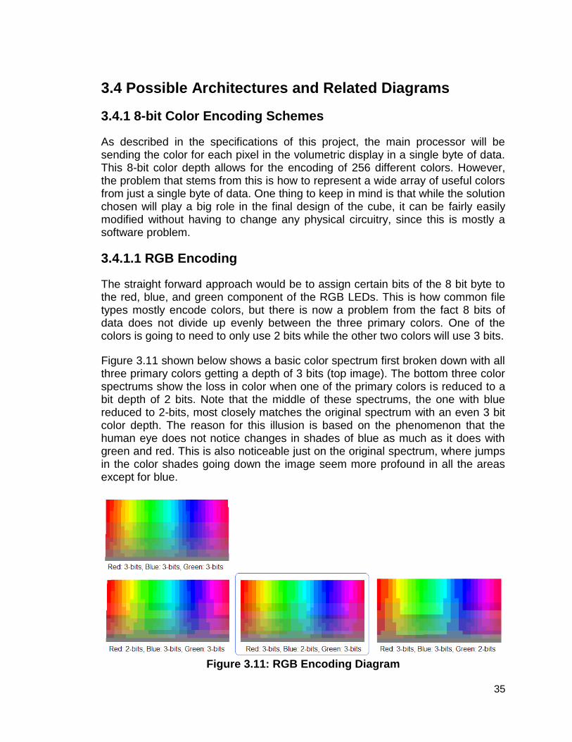
35
3.4 Possible Architectures and Related Diagrams
3.4.1 8-bit Color Encoding Schemes
As described in the specifications of this project, the main processor will be sending the color for each pixel in the volumetric display in a single byte of data. This 8-bit color depth allows for the encoding of 256 different colors. However, the problem that stems from this is how to represent a wide array of useful colors from just a single byte of data. One thing to keep in mind is that while the solution chosen will play a big role in the final design of the cube, it can be fairly easily modified without having to change any physical circuitry, since this is mostly a software problem.
3.4.1.1 RGB Encoding
The straight forward approach would be to assign certain bits of the 8 bit byte to the red, blue, and green component of the RGB LEDs. This is how common file types mostly encode colors, but there is now a problem from the fact 8 bits of data does not divide up evenly between the three primary colors. One of the colors is going to need to only use 2 bits while the other two colors will use 3 bits.
Figure 3.11 shown below shows a basic color spectrum first broken down with all three primary colors getting a depth of 3 bits (top image). The bottom three color spectrums show the loss in color when one of the primary colors is reduced to a bit depth of 2 bits. Note that the middle of these spectrums, the one with blue reduced to 2-bits, most closely matches the original spectrum with an even 3 bit color depth. The reason for this illusion is based on the phenomenon that the human eye does not notice changes in shades of blue as much as it does with green and red. This is also noticeable just on the original spectrum, where jumps in the color shades going down the image seem more profound in all the areas except for blue.
Figure 3.11: RGB Encoding Diagram

36
In the end, this means that the best RGB color encoding would be 2 bits blue, 3 bits red, and 3 bits green. This is exactly the same encoding process for the BMP file format when the color depth is set to only 256 colors (or one byte).
3.4.1.2 HSL and HSV Encoding
Another approach to encoding the colors for use in the display would be a hue, saturation, lightness encoding (or hue, saturation, value). Both of these are only slight variations of each other, in terms of the underlying math, but both result in a more polar representation of colors (like a wheel) as opposed to a grid like representation. The advantages to using this encoding over a straightforward RGB encoding stems from the fact that the LEDs being used may not be able to display darker colors or washed out colors as much as the general color spectrum. Only colors that look the best on the display should be encoded in the byte, otherwise some of the bits are essentially wasted.
Figure 3.12 shown below shows a basic encoding with 3 bits for hue, 3 bits for lightness, and 2 bits for saturation. However, this direct approach has several flaws. There are a lot of repeated colors, since no matter the hue value, if saturation is turned down all the way, all the colors will appear a shade of gray. Also, a lightness value of 0 will always result in a black and a value of 1 will always result in a white. The next color encoding, moving down from the top of the figure below, shows a better range of colors by varying saturation from only 20 percent to 100 percent and lightness from only 10 percent to 90 percent. Then, to get an all-white or all black representation of color from this, only requires two colors to be hardcoded to black or white. The color encoding showed at the bottom shows how a better spectrum of colors can be gained by reducing the bits for saturation and increasing the bits for hue. These colors may be more likely to be utilized when designing the software.
Figure 3.12: HSL Encoding Diagram

37
A downside to mention for this color encoding scheme, is the fact that it takes more processing to compute. In the end, each byte will have to be decoded into value for the primary colors, red, blue and green. RGB encoding means that the data is already in this format, where as HSL or HSV will require fairly advanced math to convert to RGB values. This may prove to be too costly when developing the logical control for the volumetric display.
3.4.2 Volumetric Display Construction
Of course one of the biggest decisions to be made when designing the display, it’s how it will be constructed. Some designs may take less time to solder together, but may also not be as structurally sound. One important thing to keep in mind for a volumetric display is the fact that there should not be too many wires in the way that might obstruct the view of the other LEDs behind them.
3.4.2.1 Common Anode per Layer
One of the more clever ways of constructing the display involves tying all the anodes of a layer together. The benefit of this design goes beyond the benefits of multiplexing. It also adds a reduction in the total amount of wires. All LEDs in a column can now share wires, instead of wires feeding to every single LED. This makes the cube appear more transparent with less to block the view of LEDs in the back. Since there are going to be 10 layers in the cube, this means the amount of wires needed is reduced by a factor of 10.
A reduction in the number of wires also allows for a much easier method of setting the LED states. Instead of addressing all one thousand LEDs individually, the hardware can simply provide only voltage to a desired layer and then ground the column the LED sits in. This allows for LEDs to be turned on from two different factors (ground, VCC) which reduces overall LED addressing overhead by the hardware. The layers simply need to be multiplexed with their appropriate column LED states at a high speed to give the illusion that all layers are being powered at the same time. This relies on the phenomenon known as persistence of vision, discussed earlier in this paper. The construction of the common anodes is shown in Figure 3.13 below.
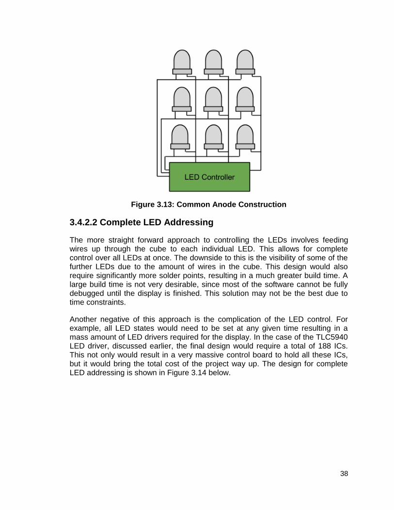
38
Figure 3.13: Common Anode Construction
3.4.2.2 Complete LED Addressing
The more straight forward approach to controlling the LEDs involves feeding wires up through the cube to each individual LED. This allows for complete control over all LEDs at once. The downside to this is the visibility of some of the further LEDs due to the amount of wires in the cube. This design would also require significantly more solder points, resulting in a much greater build time. A large build time is not very desirable, since most of the software cannot be fully debugged until the display is finished. This solution may not be the best due to time constraints.
Another negative of this approach is the complication of the LED control. For example, all LED states would need to be set at any given time resulting in a mass amount of LED drivers required for the display. In the case of the TLC5940 LED driver, discussed earlier, the final design would require a total of 188 ICs. This not only would result in a very massive control board to hold all these ICs, but it would bring the total cost of the project way up. The design for complete LED addressing is shown in Figure 3.14 below.

39
Figure 3.14: Complete LED Addressing
3.4.3 LED Control
One of the biggest tasks that need to be accomplished for this project is how to control the volumetric display and get it to show the desired images. There will be about three thousand different LEDs when factoring in RGB to control which can easily get out of hand if not controlled in a very refined manner. This brings up many different options for possible architectures in the logic control of the display, but they all at least have a few things in common.
First of all, as described above in the construction of the display, all LEDs in a layer will be connected by a common anode and all LEDs in a column will share common cathodes. This design means that only 300 LEDs will be controlled at any one time. This reduces the necessary states to keep in the LED driving component to 300 as well. This also will require high current transistors to be controlled to route the current through the correct layer at the correct time.
As part of the specifications of this project, the LED display will also need to be completely independent from the processing in the main processor. This means that a simple communication interface will need to be created where the main processor essentially writes out a buffer of data representing what the display should look like. Because of this, the control for the LED display will need to be able to store this buffer in memory so it can be used later when multiplexing through the different layers of the cube. While this requires a little more initial hardware, in the end the team believes this design decision will not only causes debugging to be easier but also allow the development of the project to become smoother.
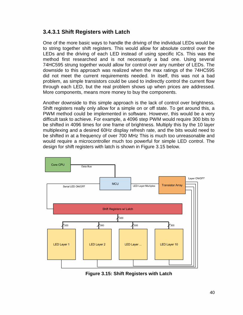
40
3.4.3.1 Shift Registers with Latch
One of the more basic ways to handle the driving of the individual LEDs would be to string together shift registers. This would allow for absolute control over the LEDs and the driving of each LED instead of using specific ICs. This was the method first researched and is not necessarily a bad one. Using several 74HC595 strung together would allow for control over any number of LEDs. The downside to this approach was realized when the max ratings of the 74HC595 did not meet the current requirements needed. In itself, this was not a bad problem, as simple transistors could be used to indirectly control the current flow through each LED, but the real problem shows up when prices are addressed. More components, means more money to buy the components.
Another downside to this simple approach is the lack of control over brightness. Shift registers really only allow for a simple on or off state. To get around this, a PWM method could be implemented in software. However, this would be a very difficult task to achieve. For example, a 4096 step PWM would require 300 bits to be shifted in 4096 times for one frame of brightness. Multiply this by the 10 layer multiplexing and a desired 60Hz display refresh rate, and the bits would need to be shifted in at a frequency of over 700 MHz This is much too unreasonable and would require a microcontroller much too powerful for simple LED control. The design for shift registers with latch is shown in Figure 3.15 below.
Figure 3.15: Shift Registers with Latch

41
When compared to the LED drivers discussed earlier in the research, it costs much less to buy the driver than the many parts of the simpler options. This is even despite the fact that the LED drivers also include more advanced features like PWM. Because of this, ICs made specifically for driving LEDs were chosen to be used in the final design instead.
3.4.3.2 LED Driver with PWM
By utilizing the TLC5940 LED driver discussed previously, the problems that arose from using shift registers can be solved much more effectively. The main benefit is being a more effective control over brightness with PWM. Instead of shifting in the 300 LED states 4096 times in a brightness cycle, only 12 bits per LED are needed to be shifted in once during the same time frame. These 12 bits represents the duty cycle from 0 to 4095 and the LED driver then implements the PWM from this data. This then reduces the data shifting frequency from over 700 MHz, as calculated before, to a much more reasonable 2.16 MHz However, to control the LED drivers themselves, additional control lines will be needed from the microcontroller. In the case of the TLC5940, this means 5 additional I/O pins are needed, but the cost is not that great compared to the benefit that is gained, thus this technology will be very useful in the final design. The design for an LED driver with PWM is shown in Figure 3.16 below.
Figure 3.16: LED Driver with PWM

42
3.4.3.3 Shared Memory Buffer
One option for keeping track of the communicated buffer of data from the main processor and the display is to simply have the main processor interface with another microcontroller. The microcontroller would then store the data in RAM where it can recall it when it's needed. The only concerns for this approach is that the micro controller would have to stop with its LED control processes to briefly pay attention to the communication with the main processor. There is also the concern that the microcontroller may not have enough RAM to even store the entire data buffer. This may also not be the best option given the concern that the main processor may be running at a much faster clock speed, forcing it to slow down when communicating data to the display microcontroller.
Another option for allowing the main processor to communicate the display data buffer to the LED control would be a shared memory access approach. The main concept for this is that the main processor would write the data buffer to a separate memory location and then the LED controlling logic device would read the data as it’s needed. The benefit from this would be that the LED control and main processor would never need to directly communicate and therefore work completely independent from each other. A FIFO register could even be used in order to reduce the amount of I/O pins needed for reading and writing. The design for a shared memory buffer is shown in Figure 3.17 below.
Figure 3.17: Shared Memory Buffer

43
One conflict that could arise from this, however, is when the LED logic tries to read the memory at the same time the main processor tries to write. Data can only be written or read at any one time, not both. To solve this problem, two memory devices would have to be used. One memory buffer would be dedicated for the LED logic to read from and the other for the main processor to write to. Once data has been completely written to one buffer, the buffers switch ownership between the main processor and LED control. So now the LED control would be reading from the newly updated data buffer provided by the main processor while the main processor writes the most recent data into the other.
3.4.3.4 RGB Color Division
One more clever approach to designing the architecture of the LED control is the concept of keeping the different colors in the RGB LEDs hardware separate. The first obvious benefit is being able to shift data to the LED drivers more efficiently. Instead of just one serial data line there would be three, allowing for three bits of data to be sent per clock cycle. This would effectively triple the maximum possible refresh rate the microcontroller can handle, since less time is wasted communicating data to the LED Drivers. Another advantage of this method is the ability to correct any sort of color errors on a hardware level. For example, if the blue diode in each LED is significantly dimmer than the other two, a simple resistor change can adjust the current running through all blue diodes, since they’re already conveniently grouped together. This will come in handy if high currents are needed to achieve the desired brightness levels, since software color correction becomes less reliable and predictable with higher currents. The design for RGB color division is shown in Figure 3.18 below.
Figure 3.18: RGB Color Hardware Separation

44
4.0 Project Hardware and Software Design Details
4.1 Overall Design Architectures and Related Diagrams
The overall block diagram in Figure 4.1 shows the three main components of the hardware and the components of the software detailed in the following sections.
Figure 4.1: Overall Block Diagram

45
4.2 Input Design
The research for choosing an appropriate input interface included possible controllers and Bluetooth device. The goal for the design was to have direct communication with a remote and the LED Cube. The final design of the input includes a Nintendo Wii remote (Wiimote) as the controller along with a USB Bluetooth dongle connected into a USB Host Mini Shield.
In order for the controller to work, seven buttons would be the minimum. Six buttons would be used for the positive and negative directions of each of the axes. As shown in Figure 4.2 below, the D-pad will be used for the x and y axis. Another button would be used to pause or initiate a menu at any time. This can be either the plus or minus button, or both. Ideally, more buttons would be desired to add more features to the animations, games, and user interface. The A button would serve as a general action button, along with the possibility of using the minus button and the B button under the controller not shown in the diagram. The z depth, seen as the straight away distance from the player’s eye position, will be adjusted with the 1 and 2 buttons. The home button will take the game to the home menu at any time.
Possible choices for the controller include any generic Bluetooth remote, mice and keyboard, to full game controllers such as the PS3 remote or Wii remote. The PS3 controller has a more traditional game controller shape and more buttons, while the Wiimote has a traditional TV remote shape and less buttons. Other useful features in the Wiimote include a 3 axis accelerometer, rumble motor, an infrared camera, and a speaker. These additional features that aren’t available on standard remotes such as keyboard allows for future expansion of features. Adding rumble feedback and sound effects during gameplay can add a lot of value. It also has an expansion port where additional devices including 3 axis Gyro and remote joystick can be connected. The Wii remote was chosen due its convenient size and ability to use vertically or horizontally. The Wii remote also contains more than enough buttons to provide all the desired features, but also keeps the interface simple for any average user to pick and use. The default controller interface will be the horizontal configuration shown at the bottom of Figure 4.2. This configuration acts as a more natural two handed control, along with a better way to quickly change between all three axes.

46
Figure 4.2: Wii Remote Input Buttons
For development, the Arduino not only allows for convenient programming through a dedicated Micro USB programming port, but it also contains a native USB port that directly communicates with the SAM3X processor. The USBHost allows the Arduino board to serve as a USB host for the processor and even includes direct software support for most mice and keyboards. Having this immediate functionality will allow inputs to quickly tested in the software. While this USBHost library doesn’t directly support other controls, by simply serving as a USB host for the processor, software can be written to support other Bluetooth

47
devices. To support the Wii remote, external libraries or software will need to be developed and applied to allow inputs to be read via Bluetooth. Until this is developed, the USBHost library will allow software to be tested with keyboard input almost immediately.
To use the any USB host for Bluetooth input, a Bluetooth dongle will be needed. Specifically, a Micro A USB Bluetooth dongle for the Arduino. The USB Host Shield Mini uses a standard USB port. Most USB dongles are available in standard USB or Micro B USB in certain cases. It is possible to use a Micro A USB port with a Micro B USB device, however not the other way around. While is possible to use a Micro USB Bluetooth dongle for the Arduino, an adapter would be the best choice. This would allow the same Bluetooth dongle to be used with the final design and during development with the Arduino. Having a USB Female to Micro USB male adapter would allow for easy use of all standard USB devices and USB Bluetooth dongles.
The final design of the input will emulate the same design as the Arduino Due. The design will use a USB host shield that will be attached to an AVR microcontroller. The USB host shield will take in a USB Bluetooth dongle that will provide the Bluetooth signal necessary to communicate with the input device for the cube. In order to program the AVR microcontroller, AVRDude has been chosen as a useful utility that will accomplish what is needed. Through this tool, all Bluetooth code needed to handle the Wiimote input signals needs to held on the AVR microcontroller.
The initial design of the input should allow for several input choices. Having several choices will allow the design to be flexible for cases in which certain controls or other peripheral devices fail to perform correctly. The best choice to achieve this design includes using a USB host and a Bluetooth dongle. Using this configuration, any standard USB device can be used as an input. Using a USB Bluetooth dongle and a Nintendo Wii Remote, users will be able to directly control the LEDs on the cube.
To control the LED cube with a Wiimote a connection between the USB Bluetooth dongle and Wiimote must be initialized. Before this is possible, a successful USB host connection must be made with the USB Host Shield Mini. The USB Host Shield Mini was design to use the Arduino Mini board right away, however can be used as a general MAX3421E breakout board. The MAX3421E works was a USB host controller using SPI. To connect the Shield to our microcontroller the SPI pins must be mapped together, the pin mapping for the Shield is shown below in Figure 4.3. VIN and GND pins will be used for the power and the four SPI pins will connect to the four corresponding pins on the microcontroller.
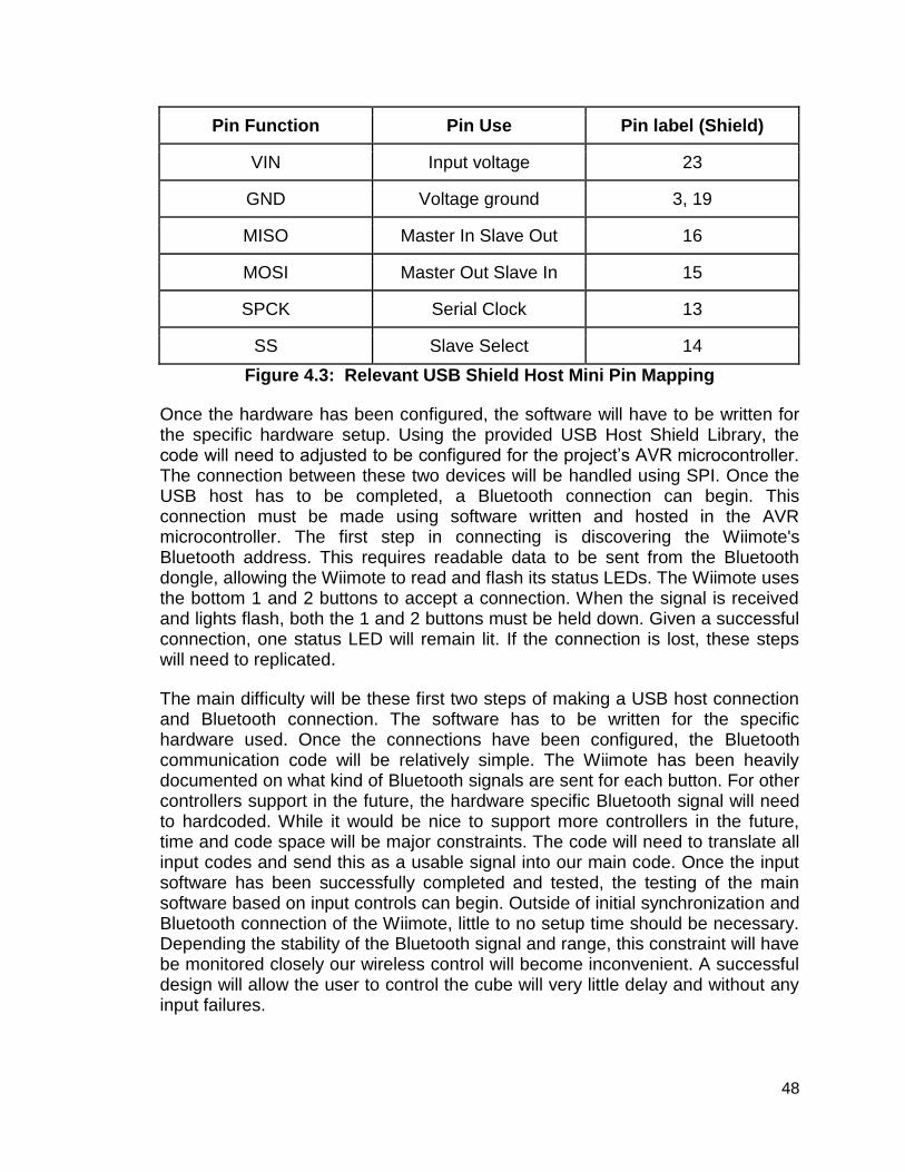
48
Pin Function Pin Use Pin label (Shield)
VIN Input voltage 23
GND Voltage ground 3, 19
MISO Master In Slave Out 16
MOSI Master Out Slave In 15
SPCK Serial Clock 13
SS Slave Select 14
Figure 4.3: Relevant USB Shield Host Mini Pin Mapping
Once the hardware has been configured, the software will have to be written for the specific hardware setup. Using the provided USB Host Shield Library, the code will need to adjusted to be configured for the project’s AVR microcontroller. The connection between these two devices will be handled using SPI. Once the USB host has to be completed, a Bluetooth connection can begin. This connection must be made using software written and hosted in the AVR microcontroller. The first step in connecting is discovering the Wiimote's Bluetooth address. This requires readable data to be sent from the Bluetooth dongle, allowing the Wiimote to read and flash its status LEDs. The Wiimote uses the bottom 1 and 2 buttons to accept a connection. When the signal is received and lights flash, both the 1 and 2 buttons must be held down. Given a successful connection, one status LED will remain lit. If the connection is lost, these steps will need to replicated.
The main difficulty will be these first two steps of making a USB host connection and Bluetooth connection. The software has to be written for the specific hardware used. Once the connections have been configured, the Bluetooth communication code will be relatively simple. The Wiimote has been heavily documented on what kind of Bluetooth signals are sent for each button. For other controllers support in the future, the hardware specific Bluetooth signal will need to hardcoded. While it would be nice to support more controllers in the future, time and code space will be major constraints. The code will need to translate all input codes and send this as a usable signal into our main code. Once the input software has been successfully completed and tested, the testing of the main software based on input controls can begin. Outside of initial synchronization and Bluetooth connection of the Wiimote, little to no setup time should be necessary. Depending the stability of the Bluetooth signal and range, this constraint will have be monitored closely our wireless control will become inconvenient. A successful design will allow the user to control the cube will very little delay and without any input failures.

49
4.3 LED Cube Design
The LED Cube will be composed of 5mm RGB LEDs arranged in a common anode per layer design. There will be a total of 300 leads, which will be routed from the cube to a PCB board via ribbon cables. The PCB board will contain all the logic and power for the display, including the LED drivers. The microcontrollers to be used in the LED logic will be the MSP430. A single 10 pin connector will also be on the PCB board for the main processor to interface and write to the display. The final array of LEDs will be encased in acrylic and stand on top of the base of the final project.
4.3.1 LED Assembly
The assembly of the cube will involve a three step process similar to the same process described by Kevin Darrah in his 8x8x8 cube. The first step is to solder the RGB LEDs into columns of 10 LEDs. A column consists of LEDs soldered together by their three cathodes. This makes all LEDs in a column share a common cathode for both the red, green and blue diode. A simple rig, made out of wood, will be constructed to hold the LEDs and wire in place while they are soldered together. The rig is constructed perfectly so that there is exactly 10 inches between the first and last LED, shown in Figure 4.4 below.
Figure 4.4: Column Soldering Rig

50
The second step in the LED cube assembly involves soldering the columns into sheets or slices. This is done by soldering all anodes in a layer together along a piece of wire. A separate rig will be constructed to hold the wire straight and provide markings to ensure spacing between the columns is precise, shown in Figure 4.5 below.
Figure 4.5: Sheet Soldering Rig
The final step in the assembly of the LED cube will involve soldering the sheets together into the final cube. To accomplish this, a solid wood base will have holes drilled into at precisely measured positions. This will act as a sort of rig and ensure that the sheets remain straight when being soldered together. The cathodes of the LED columns will fit through the holes to hold the sheets in place. Each sheet will then be soldered together with a single wire along the side for each layer. This now will ensure that all anodes in a layer are tied together. Once all the sheets have been soldered together into the final cube, the cathode and anode leads will be tied to ribbon cables which will allow for easy hook up to a control board with sockets for the cables. The assembled cube is shown in Figure 4.6 below.
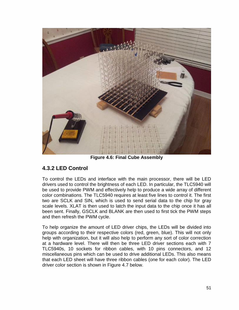
51
Figure 4.6: Final Cube Assembly
4.3.2 LED Control
To control the LEDs and interface with the main processor, there will be LED drivers used to control the brightness of each LED. In particular, the TLC5940 will be used to provide PWM and effectively help to produce a wide array of different color combinations. The TLC5940 requires at least five lines to control it. The first two are SCLK and SIN, which is used to send serial data to the chip for gray scale levels. XLAT is then used to latch the input data to the chip once it has all been sent. Finally, GSCLK and BLANK are then used to first tick the PWM steps and then refresh the PWM cycle.
To help organize the amount of LED driver chips, the LEDs will be divided into groups according to their respective colors (red, green, blue). This will not only help with organization, but it will also help to perform any sort of color correction at a hardware level. There will then be three LED driver sections each with 7 TLC5940s, 10 sockets for ribbon cables, with 10 pins connectors, and 12 miscellaneous pins which can be used to drive additional LEDs. This also means that each LED sheet will have three ribbon cables (one for each color). The LED driver color section is shown in Figure 4.7 below.

52
Figure 4.7: LED Driver Color Section
Since the LEDs are not all going to be on at the same time, a microcontroller is needed to handle the multiplexing of the individual layers. To do this, the MSP430F5529 is implemented in the design since it has a clock frequency of 25MHz, closely matching the TLC5940 max serial data transfer speed of 30MHz. This microcontroller is also selected due to its high amount of I/O pins. To select the columns to light, the microcontroller interfaces with the three color LED driver sections. To select a layer, the microcontroller interfaces with an array of transistors which selectively provide power to only one layer at a time. Finally, in order to receive video data from the main processor, a separate shared memory buffer is used. This allows an asynchronous data transfer to occur between the two devices even if the main processor is running at speeds much faster than the LED control microcontroller. The LED control design is shown in Figure 4.8 below.
Figure 4.8: LED Control
53
The video data stored in the external RAM memory chip will be stored in the format of one byte per LED to denote color. The reason for this is to improve the amount of time it takes for the main processor to output a frame. The separate modular approach for the LED control will also help improve video output times for the main processor. For example, if the main processor was to control the TLC5940 LED drivers directly, it would take a considerably more amount of time to output all desired LED states. All LED data would need to be shifted in with 12 bits per color. That’s 26 bits per LED for one thousand LEDs. If only one bit can be shifted in at a time it would take 26000 clock cycles. Encoding each LED into a byte and allowing a byte to be output in a single clock cycle, it only takes 1000 clock cycles to output video data. This speeds up the data transfer by a factor of 26.
4.4 Microcontroller Design
The microcontroller board will be based on the Arduino Due board. The Arduino Due is part of the Arduino line of single-board microcontrollers. The Arduino’s feature open-source hardware board designed around 8-bit Atmel AVR or 32-bit Atmel ARM. The Arduino Due is based on the Atmel SAM3X8E ARM Cortex-M3 CPU. The ARM Cortex-M3 executes the Thumb2 instruction set for optimal performance and code size, including hardware division, single cycle multiply, and bit-field manipulation. The Cortex-M3 is able to deliver up to 240 system interrupts with individual priorities. The Arduino Due has 54 digital input/output pins. These pins 12 that can used as PWM outputs, 12 analog inputs, 4 UARTs (which will be used for transmit/receive with Bluetooth), and an 84 MHz clock. Connections for the board include an USB OTG capable connection, 2 digital to analog, 2 TWI, a 2.1mm power jack, an SPI header, a JTAG header, a reset button and an erase flash button. This allows programming of all the software to be done using the micro USB programming port on the board.
The important factors of this board when integrating it with the LED cube and Bluetooth include the pin connections and the power. The microcontroller has an operating voltage of 3.3V but the board must be supplied with 7-12V to be stable. The board contains a voltage regulator to manage any spikes and fluctuations of the provided voltage. The microcontroller will be powered by the power supply to VIN/GND pins of 7-12V. For programming the board will be powered by the micro USB connection. The microcontroller will also power any Bluetooth module using the 3.3V output pin. Each of the 54 digital pins on the Due can be used as an input or output, using software functions.
Each pin operates at 3.3 volts such as the microcontroller and the possible Bluetooth module. Pins 14 and 15 (TX3 and RX3) will be used as the serial receive and transmit with any Bluetooth module used. The Bluetooth module will also connect to one of the four GND pins and to the 3.3V pin. Other pins may be necessary to use depending on the Bluetooth module specific settings that may require pins from the Arduino or a breakout board. The relevant pins that will be

54
used are shown in Figure 4.9 below. For a Bluetooth dongle, the USB will be used rather than these pins. Our final design will include a USB host, thus for testing with the Arduino Due, a Bluetooth dongle will also be used.
Pin Function Pin Use Pin label (Due)
VIN Input voltage VIN
GND Voltage ground GND
3.3V Bluetooth power 3.3V
TX3 Bluetooth transmit 14
RX3 Bluetooth receive 15
Digital I/O LED Cube output data 22-53
Figure 4.9: Relevant Arduino Due Pin Mappings
The Arduino microcontroller has 512 kilobytes flash made up of 2 blocks of 256 kilobytes for storing code. The available SRAM is 96 KB in two contiguous banks of 64 KB and 32 KB. All the available memory (Flash, RAM and ROM) can be accessed directly as a flat addressing space. The Arduino has an erase button onboard that will erase the Flash memory of the SAM3X which will remove the currently loaded Arduino sketch from the memory.
The Arduino serves as a good reference for the requirements needed to design the microcontroller portion of the project. Given the selection of the AT32UC3A0512 microcontroller, the board design must allow the microcontroller to communicate with a USB host and the LED circuit. This will allow the microcontroller board to still remain modular. The first component of the design will be mapping the needed pins. Pins needed include the power pins, GPIO for the LED circuit and SPI for programming and Bluetooth.
The pin labels on the AT32UC3A0512 are shown below in Figure 4.10. Each GPIO controller controls 32 I/O lines. The 32-bit GPER signal controls how each I/O line is assigned. Each bit corresponds to the same number pin the I/O line, a bit of 0 assigns the I/O pin to the peripheral signal, a bit of 1 assigns the I/O pin to the drive of the GPIO control. The GPIO units are split into PA, PB, PC, and PX. Two SPI units are available for use in the PX GPIO. To simplify the design, no more than two I/O lines will be used. Each I/O line has up to 32 usable pins, more than enough to communicate with Bluetooth through SPI and for the LED output. Ten I/O pins will be assigned was output for the LED circuit and four will be assigned for SPI.
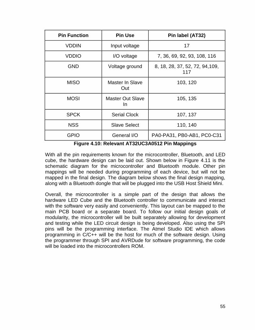
55
Pin Function Pin Use Pin label (AT32)
VDDIN Input voltage 17
VDDIO I/O voltage 7, 36, 69, 92, 93, 108, 116
GND Voltage ground 8, 18, 28, 37, 52, 72, 94,109, 117
MISO Master In Slave Out
103, 120
MOSI Master Out Slave In
105, 135
SPCK Serial Clock 107, 137
NSS Slave Select 110, 140
GPIO General I/O PA0-PA31, PB0-AB1, PC0-C31
Figure 4.10: Relevant AT32UC3A0512 Pin Mappings
With all the pin requirements known for the microcontroller, Bluetooth, and LED cube, the hardware design can be laid out. Shown below in Figure 4.11 is the schematic diagram for the microcontroller and Bluetooth module. Other pin mappings will be needed during programming of each device, but will not be mapped in the final design. The diagram below shows the final design mapping, along with a Bluetooth dongle that will be plugged into the USB Host Shield Mini.
Overall, the microcontroller is a simple part of the design that allows the hardware LED Cube and the Bluetooth controller to communicate and interact with the software very easily and conveniently. This layout can be mapped to the main PCB board or a separate board. To follow our initial design goals of modularity, the microcontroller will be built separately allowing for development and testing while the LED circuit design is being developed. Also using the SPI pins will be the programming interface. The Atmel Studio IDE which allows programming in C/C++ will be the host for much of the software design. Using the programmer through SPI and AVRDude for software programming, the code will be loaded into the microcontrollers ROM.

56
Figure 4.11: Microcontroller Design
4.5 Power Design
One of the main goals of the project was to make a modular design in which the three main hardware components would be as independent as possible. The three main components include the LED logic circuit, the main microcontroller, and the Bluetooth module. The main goal for the power supply was the ability to plug the final product straight into the wall. To complete both of these goals, each component needs to be powered separately. The best way to achieve is to use an ATX PC power supply. The group has immediate access to an ATX power supply for testing. In the future an upgrade to a Micro-ATX power supply would be possible. A Micro-ATX offers the same features in a smaller package, which could be useful if space in the base of the project becomes an issue. An ATX PC power supply is able to supply various voltage amounts to several sources, along with plenty of current. Each component would be responsible for implementing any needed voltage regulators and/or coupling capacitors to guard against voltage fluctuation. This will allow the power supply to be easily connected and disconnected to each part of the project. To use an ATX power supply, the voltage requirements for each component of the project must be matched to voltage provided from the power supply. The power requirement for each component of the project is shown below in Figure 4.12.
The power supply used in the initial design is the Kingwin KWI-350WS, a 350 watt ATX power supply. The voltage specifications of this power supply are shown below in Figure 4.13.

57
Component Power Requirements Power Supply Line
LED Circuit 3.3 V, 1.5 A +3.3V, GND
AT32UC3A0512 3.3 V +3.3V, GND
USB Host Shield Mini 3.3 V +3.3V, GND
Power Switch - PS On, GND
Figure 4.12: Power Requirements
DC Output +3.3V +5V +12V -12V -5V +5VSB
28A 35A 16A 0.8A 0.5A 2A
Figure 4.13: KWI-350WS Specifications
Not only does the main ATX power cable have three +3.3V lines available to use, but also provides several other options in case any more power is needed. The LED cube requires a significant amount of current to power all the LEDs depending on how many are on at a given time. This power supply provides more than enough current in the 3.3V line, 28 A. Being as the power supply is built for use by a PC, all wires are connected into various connectors. To use the power supply in our design, the wires must be cut from the connectors and wired to the circuits. The main 20-pin ATX connector alone contains all the wires needed. Not only does it have three +3.3V lines and the corresponding ground, but it also has PS On line to turn on the power supply.
Many ATX power supplies require a significant load to be connected on a line to turn on the power supply, initial testing of the KWI-350WS power supply shows this will not be a needed. This means once the switch is pressed on the back, the power supply will turn on and start the cube. To make the project a more convenient package, a power button will be integrated similarly to a PC. To allow the power supply to turn on at the press of a custom power switch the PS On line and a ground must be connected to a switch. Normally when the main ATX connector is plugged into a socket, the PS On switch is connected allowing for the power supply to turn on. When activated, along with the power supply being plugged into the wall and main switch flipped on, the power supply will power all components and the project can run.
The final power design inside the final housing of the cube can be seen in Figure 4.14 in section 4.6. Overall, three +3.3V lines with a ground line for each are connected to the three components, and one PS On with ground is connected to a switch.

58
4.6 Housing Design
The housing has two main parts: the electronics housing and LED housing. The electronics housing is the base of the project which holds the electronics inside and holds the LEDs above. The inside of the electronics housing can be seen below in Figure 4.14. All electronics including the LED circuit, microcontroller, USB Host, power supply, and power button are inside. The base will be 14’ x 14’ x 4’.
Figure 4.14: Electronics Housing Diagram
The base will be a rectangular prism made with wood. Three sides and the bottom will completely solid and fixed. The top will contain cutouts to wire the LEDs. The back side will be removable to access the electronics inside, however

59
the final design will have the circuits screwed in place, so any modifications will require the bottom to be removed. To avoid this, complete final functionality should be verified before affixing the circuits. The back side will also contain cutouts at the power supply in order to plug in the power cable, access the power switch, and allow the PSU fan to ventilate. Different materials and different types of wood are being considered for optimal functionality, weight, and presentation.
The second component of the housing is the LED encasing, shown below in Figure 4.15. To protect the LEDs, five acrylic sheets will be used. Two acrylic sheets will be 12’ x 10’, two will be 10’ x10’, and the final top sheet will be 12’ x12’. Different acrylic widths are being considered for optimal view, protection, and ease to cut. Most likely the width will be 5mm or less. To cut the acrylic many options are available including sharp cutting blades, handsaws, or saw blades. After cutting the edges must be smoothed down and chemically attached to each other, then embedded into the top of the base. Together, both parts should offer the project good protection and good presentation.
Figure 4.15: Electronics Housing Diagram
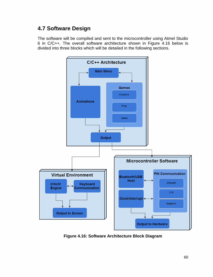
60
4.7 Software Design
The software will be compiled and sent to the microcontroller using Atmel Studio 6 in C/C++. The overall software architecture shown in Figure 4.16 below is divided into three blocks which will be detailed in the following sections.
Figure 4.16: Software Architecture Block Diagram

61
For testing with the Arduino Due the software will be sent as an Arduino sketch using the Arduino IDE in C/C++. Initial design and implementation of the code will be developed and ran in Microsoft Visual C++ 2010. The reasoning behind this is due to the virtual environment the group will use as simulation is implemented in Visual C++. Atmel Studio is also very similar to the Visual C++ IDE. With the exceptions of certain unsupported functions the code should be completely portable from the virtual environment in Visual C++ to the LED Cube in Atmel Studio 6 and the Arduino IDE.
The basic architecture of the software design is creating a 1000 byte output with the color for each LED. This will all be implemented in common C/C++ code that will create an array of data. Using this virtual environment, software will build the simulated cube and display the data. The Arduino IDE will do the same thing, however instead of initializing the virtual cube, the hardware pins/output, clock and interrupt cycles, and Bluetooth input must be managed. The AT32 microcontroller must also implement the USB host software.
4.7.1 Virtual Environment
As part of the theme of modularity, a virtual representation of the LED Cube was needed. A virtual cube would allow the software to be developed immediately with an accurate simulation environment. As long as the final output of the code is the same, the virtual environment and the physical LED cube should ultimately function the same if both are built correctly. The virtual environment allows for immediate testing and compiling of the code which will allow the software phase of the project to evolve immediately. To create the virtual environment the team will utilize the Irrlicht Engine. The Irrlicht Engine is a cross-platform high performance real-time 3D engine written in C++ in the forms of downloadable libraries. It features a powerful high level API for creating complete 3D and 2D applications, for our purpose a 3D LED cube.
Utilizing Visual Studio IDE for using the Irrlicht Engine is very simply implemented. The basics of the engine include the VideoDriver, the GUIEnvironment, and the SceneManager. The engine is available are free to download SDK. To use the engine the code must include the header file <irrlicht.h>. With this header the group was able to build the Virtual Environment.
The first function the environment uses is the createDevice() function. The IrrlichtDevice is created by it, which is the root object for doing anything with the engine. createDevice() has parameters that control the software renderer, window size, color bit size, and more. CInputReceiver() is the function used to control input from the mouse and keyboard. Using these two functions the virtual environment shell that acts as simulation for the LED cube and Bluetooth controller has been created. From here the rest of the virtual environment will be built.
62
The virtual environment is made up of main and CVirtualEnvironment that interface with Irrlicht engine directly. To create our custom virtual environment, CVirtualEnvironment was created. This is the main virtual environment file for our simulated LED cube. This class utilizes the Irrlicht functions to draw to the screen, a version of this class will need to be recreated to interface with the actual LED cube and the Bluetooth input device. Along with main and Irrlicht library, CVirtualEnvironment ends the extent of simulation based code. The rest of the classes should nearly independent of the output method. The CSceneManager class is the main class to keep track of different objects in our program to draw and move, this class will used in the final Arduino software. Referencing the software block diagram, this class could be considered part of the C/C++ software that will build objects and draw them based on the animation/game logic. This class is the main software focus, adding and testing functions to efficiently create objects to draw to the cube. Given the final design of the games and animation, most objects should be directly implemented in this class in some way. More complicated games/animation object would most likely need a combination of several objects or specific to their class.
Classes in this block will interface with the virtual environment or the Arduino environment with little changes necessary. Main in our virtual environment will utilize CVirtualEnvironment to draw to the screen. Main will utilize the rest of the classes such as CSceneManager and future game classes to complete the tasks required for the project software.
The virtual environment works by using the built in scene manager of the Irrlicht Engine. This is different than the teams implemented scene manager, which extends this to make more objects specific to our games/animations such a star as seen in the next figure. The engine support main basic models. To make an LED Cube simulation, 1000 cubes is all that is needed from the Irrlicht Engine. Other functions of engine include setting and moving the camera, and complete keyboard and mouse input controls. Using simple nested for loops, 1000 Cubes are drawn using the scene manager with each having the position set. Drawing of objects such as cubes contains support for many familiar graphical options including diffuse, ambient, and specular colors. A simple transparent texture is used for default cubes to simulate an LED off. From here, any drawn cubes will turn on by setting the color to a buffer. The buffer will be 1000 bytes, each corresponding to RGB value of one LED/cube. This allows for an 8-bit color to be displayed, 3 bits for red, 3 bits for green, and 2 bits for blue, a palette of 256 colors. This buffer code is set to be close to what the output from the Arduino to the hardware cube will be. Thus any code that leads to generation of a 1000 byte buffer, could easily ported to the final software. A scene with 1000 cube objects configured to display a large cube outline and star is shown in Figure 4.17 shown below.

63
Figure 4.17: Virtual Environment with a cube and star drawn to the screen
Overall, the virtual environment software requires little effort compared to the time it will save in testing the software in the final hardware. Not only will it facilitate in testing the games and animations, Wiimote controls using a Bluetooth dongle connected to a PC can be used to test the input controls and button configuration. This would require very little effort because all that is needed to use a Wiimote with a PC is the correct drivers. The final design will require a lot of effort before it is ready to test the input configuration. Additionally, the virtual environment will allow the games and animations software to begin development immediately without the hardware completed.
4.7.2 Arduino Software
The Arduino Software can be used to verify the functionality of the microcontroller component of the final design. This code will not be used in the final design but portions implemented will be portable to the final code. The code should use the same concept as the virtual environment software. All C/C++ software developed that leads to an output buffer of 1000 bytes should be portable between each block. The difference will lie in the lower level software that handles the hardware specific pins and timers. The virtual environment

64
requires initialization and utilization of functions in the Irrlicht engine. The Arduino environment will require initialization of the pins and timers. The LED drivers will configure any color depth options and brightness options. The Arduino software will implement a similar system as main from the virtual environment. After hardware specific initializations, a basic menu will be implemented to choose different modes including games and animations. Main will take the output from these classes and configure it for correct output and also relay the Bluetooth input. From there, the Arduino specific code only needs to handle Bluetooth input as the animations and games will be coded hardware independent in C/C++ leading to the 1000 byte buffer output. This will allow for portability to the final design.
Arduino software uses sketches that output to the hardware and are stored in the flash memory. The first thing that will run in the main file will be the setup() function that will run only once at the beginning. Setup() will be used it to initialize variables, pin modes, and name any used external library classes. The pinMode() function will be used to set up the output pins to the hardware cube. Ten digital output pins will most likely be used send the buffer data to the cube. The setup of these pins will follow the format of pinMode(pinNumber, OUTPUT). Serial communication will be configured by setting the serial baud rate, bits per second, by using Serial.begin(speed). Bluetooth input may use the serial communication features including Serial.read() if an external Bluetooth chip is used. If a Bluetooth adapter is used to connect straight to Arduino’s Micro USB the Arduino USBHost() library will be used to configured input commands. The inputs will be used in the main loop to relay controls to the animations and games software.
To sync the output with the cube refresh rate implemented in the LED circuit, the output should be sent after the same certain period of time. This will be achieved using the Arduino software timers. The Arduino timer is implemented directly in the hardware as a clock. Several timers are available at either 8-bit or 16-bit. They can be used by setting special registers in the software. The timer frequency that is desired can be configured using the CPU frequency and maximum timer counter value (256 for 8bit, 65536 for 16bit timer). The next step is determining what frequency to set the timer by dividing the clock speed by a prescaler. The timer will be configured to generate an automatic interrupt from our code after the desired time and send the output to the hardware, acting as a software refresh rate that will make that of the hardware.
After setting up the output pins, input communication, and timers, the code will then be able to move to loop(). From here the code will run the main menu, animation, and games. The extent of Arduino specific code should remain in the main class which will control hardware input and output and the main menu. Additional software for testing of the Bluetooth controller may also be implemented. The animations and games should require very little to none Arduino functions.

65
4.7.3 Microcontroller Software
The microcontroller software for the AT32UC3A0512 will be very similar to the Arduino software used during testing. Specific code for the hardware must be initialized, along with USB host software. Both the Arduino and AT32 should be able to use nearly identical Bluetooth software for the Wii remote. The main difference in software will be the USB host will be completely different. By using the Arduino, the Wii remote specific Bluetooth software can be verified and tested on both sources, helping to isolate Bluetooth bugs away from USB hosting bugs. The previous software written for the animations and games should be independent of the AT32. The AT32 must initialize the SPI interface between the microcontroller and the USB Host Shield. The AT32 must also initialize the general output pins to the LED cube. The GPIO lines must be set and configured for correct input or output. After the hardware specific code, it should be nearly identical to the Arduino software. The loop and starting of a basic menu will be implemented to choose different modes including games and animations. Main will take the output from these classes and configure it for correct output and also relay the Bluetooth input. From there, the microcontroller specific code only needs to handle Bluetooth input as the animations and games will be coded hardware independent in C/C++ leading to the 1000 byte buffer.
4.7.4 Animations and Games
The animations and games software should be hardware and output independent. Regardless if whether the virtual environment or hardware LED cube is configured fully, this code can be developed. The main requirement is the ability for these classes is to provide the current output buffer at any time. The virtual environment will draw continuously as draw calls are made from the virtual environment software. The microcontroller software will interrupt the code and request the current output. For both cases, functions to immediately return the current output buffer will need to implemented. C/C++ will be used due to the immediate support of the hardware being used but other high level languages may also accomplish the same goal.
Animations have endless possibilities of combinations of different shapes and colors and length. The first priority is to develop of a set of consistent transition animations for changing modes of the LED Cube. With no real text feedback, the cube must use a consistent set of animations and transitions to allow the user to understand what is happening. Text output could be a possible animation. Using enough LEDs, readable text can be written and scrolled through on one face of the cube. Because readable text does not take advantage of the 3D aspect of this project, visual animations will be favored when possible. Using a face of the cube, each letter can be programmed in the code and strings can be input to display output messages. The main use of text output will in the menu selections. Initial basic transition animations can include toggling each layer on from the bottom to the top leaving each on until all layers are on, simulating a loading
66
screen. Interactive animations will also be implemented. Rather than a full game that takes in user input, basic animations with effects can also utilize user controls. Animations that can shift direction and color on the fly as the user provides input will be added. A combination of loading screen animations and text output could lead to a very clear and consistent user interface. Several animations can be stored along with the games to show the color effects possible by the cube. A good set of basic animations can lead to a good infrastructure of code to reuse for the more complex games.
Games will be limited to those that can implemented in relatively low resolution. This includes many classic games such as Snake, Pong, and Tetris. The games will be developed to bring a 3D aspect to them. A snake would not only navigate towards pellets to eat in the normal 2D plane, but also be able to move up each layer. Rather than having each of the four 2D walls like in traditional snake, each of the six faces will act as walls. Each face will act as the final plane the snake can legally be in. Going beyond any of the face layers will cause the death of the snake and end of the game. After the end of each game play through, a menu to replay or go back to the game menu will be used. That menu will allow the choosing of all the games along with the ability to return to the main menu. Pong will consist of 2 paddles on the face on two sides of the cube that would move in 2 axes rather than the one axis. The paddles can be on each of the four sides, or possibility the top and bottom as well. If using the sides as the paddles home, the player can shift their position to get either a side view of the scene or straight view of the scene. The paddles will be able to set at different sizes for different difficulties such as 2x2 or 3x3. The ball will be either a single LED or a cube of multiple LEDs and as long as it collides with one of the paddles LEDs then it will bounce back to the other side. The other four sides not used for the paddles home will act as walls the ball can bounce off of. Pong and Snake offer a very realistic playing scheme for the LED cube. More complex games such as Tetris bring new challenges.
Tetris would allow the filling of each y axis layer with 3D Tetris objects before clearing the layer. These games must tailored to the hardware and customized to create the best look on the cube. The nature of Tetris causes the screen to fill out and leave gaps in the screen depending on user play. This may prove difficult to implement due to the depth of the cube and ghosting. For example, filling the 2nd y layer of the cube and the entire 1st layer of the cube except one point would be very hard to see. All LEDs surrounding the empty point would be lit up, causing the empty LED to look lit. To fix this, along with other games, new rules and conventions will need to be made. 3D Tetris may be implemented in order to prevent empty spots in a layer.
Other games that will be harder to implement such as 3D Checkers and 3D Asteroids will be attempted. Custom games that make sense in a 3D environment would be ideal and could take advantage of display effects the best. All games will contain the software needed to have the game logic to run, and the code that will take the objects that need to drawn and convert it to the standard

67
buffer output format. Games will have a minimum input requirement of 6 directional buttons for the x, y, and z movements.
With a smooth and consistent set of menu animations and transition animations, the usability of the cube could be very high despite the limited pixels. Together with a good set of animations and games, the software can allow the LED cube to become a fun and interactive environment.

68
5.0 Design Summary of Hardware and Software
The 10x10x10 LED Cube includes both hardware and software design. The hardware design begins with the physical construction and soldering of the 1000 LEDs. Controlling that includes the logic design made using a custom circuit. The main microcontroller will serve as the host of the software and mediate between the output and the input. The software design includes designing a successful simulation environment and designing animations and games to function in a 3D display.
5.1 Parts List
The initial parts chosen by the group based on initial research are shown in Figure 5.1 below. The category and part chosen is shown with the source of the purchase and price. Most parts were purchased online. Many of electronic components such as the LEDs were cheapest on EBay but required long shipping times. More detailed information on parts selection is available in section 6.1 and budget and shipping is available in the section 8.2. Many of the parts have already been purchased, while other parts are still being researched or searched for.
Category: Part Chosen Source Price
LEDs: 5mm RGB LEDs x1000 Ebay.com $60
Main Microcontroller: AT32UC3A0512 Atmel.com 0
LED Cables: 10pin Ribbon Cable Ebay.com $15
LED Cables: Standard Wire Skycraft $15
LED Cables: Ribbon Cable Sockets x20
Ebay.com $10
Logic Circuit:28pin DIP IC Sockets x5 Ebay.com $5
LED Drivers: TLC5940NT x20 Ebay.com $17.50
LED Microcontroller: MSP430F5529 Texas Instruments
0
Logic Circuit: Resistors/Capacitors --- 0
SRAM 256K 3.3V: AS7C3256A-10TCN Mouser.com $1.50
Bluetooth Input: Bluetooth dongle Amazon.com $1
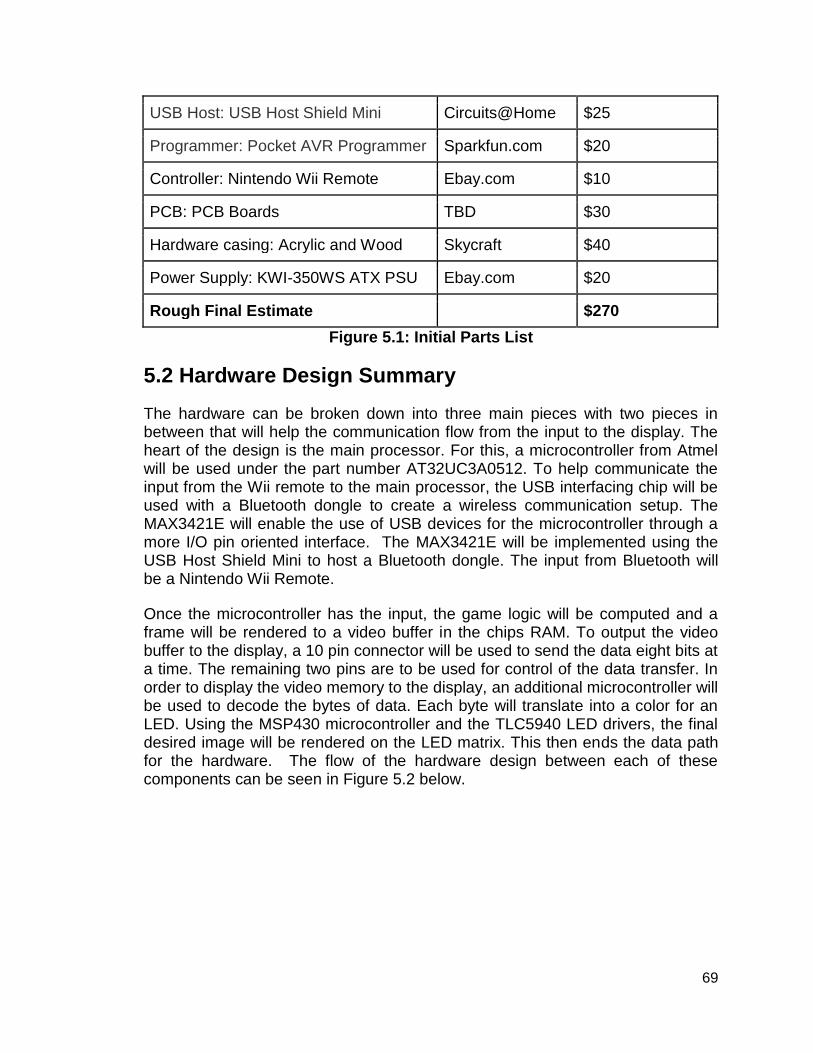
69
USB Host: USB Host Shield Mini Circuits@Home $25
Programmer: Pocket AVR Programmer Sparkfun.com $20
Controller: Nintendo Wii Remote Ebay.com $10
PCB: PCB Boards TBD $30
Hardware casing: Acrylic and Wood Skycraft $40
Power Supply: KWI-350WS ATX PSU Ebay.com $20
Rough Final Estimate $270
Figure 5.1: Initial Parts List
5.2 Hardware Design Summary
The hardware can be broken down into three main pieces with two pieces in between that will help the communication flow from the input to the display. The heart of the design is the main processor. For this, a microcontroller from Atmel will be used under the part number AT32UC3A0512. To help communicate the input from the Wii remote to the main processor, the USB interfacing chip will be used with a Bluetooth dongle to create a wireless communication setup. The MAX3421E will enable the use of USB devices for the microcontroller through a more I/O pin oriented interface. The MAX3421E will be implemented using the USB Host Shield Mini to host a Bluetooth dongle. The input from Bluetooth will be a Nintendo Wii Remote.
Once the microcontroller has the input, the game logic will be computed and a frame will be rendered to a video buffer in the chips RAM. To output the video buffer to the display, a 10 pin connector will be used to send the data eight bits at a time. The remaining two pins are to be used for control of the data transfer. In order to display the video memory to the display, an additional microcontroller will be used to decode the bytes of data. Each byte will translate into a color for an LED. Using the MSP430 microcontroller and the TLC5940 LED drivers, the final desired image will be rendered on the LED matrix. This then ends the data path for the hardware. The flow of the hardware design between each of these components can be seen in Figure 5.2 below.

70
Figure 5.2: Hardware Design Flow
The overall construction of the cube will involve soldering together all one thousand LEDs in a common anode per layer design and include over 4000 solder points with over 500 feet of wire. Due to time constraints, construction of the cube will begin very early in the design process, since it is so vital to the debugging of the additional hardware.
A clear Plexiglas/acrylic enclosure will be made for the display to protect it from being damaged and wire shorting. This display of LEDs will then be mounted on a box base which will house the additional hardware components. Inside will include the microcontroller board, the USB Host and Bluetooth dongle, the LED circuit, and the power supply. The end result should expose no internals and only have a power cord, power button, and indicator LEDs visible. The power cord will connect directly to the power supply and when turned on will not activate the cube. Like a PC, the power supply will not start when the switch is turned on but instead be wired to turn on with a push button on the front of the LED cube. Finally, the Wii remote will be the last component of the hardware. Figure 5.3 below shows a conceptual rendering of the final product.

71
Figure 5.3: Conceptual Rendering
5.3 Software Design Summary
The LED Cube software will be hosted in the AT32UC3A0512’s flash memory. The software will be no more than 512 KBytes in size. The basic software design is shown in Figure 5.4 below.
Before the main menu can ran from the flowchart a lot of software design will be needed to completed. This includes the software needed to have a stable USB host connection with the USB Host Shield mini and software to have a stable Bluetooth connection with the Bluetooth dongle. This code will be part of the set up and be hardware specific. The USB host code will interface with the MAX3421E using SPI. The Bluetooth code will interface with the Host Controller Interface in Bluetooth dongle to communicate with the Wii remote.

72
Figure 5.4: Software Design Flowchart
The software will run on the AT32UC3A0512 and must begin with the setup() function. Here the software will initiate any global variables and configure the board for the input and output. The output will be configured for the 10 digital output pins connected to the LED circuit. The input will be configured to have a USB host Bluetooth connection. To allow support for other devices rather than mice and keyboard, the software design must include Wii remote support.

73
Depending on how the Nintendo Wii Remote sends Bluetooth signals, the software must be able to decipher each input and incorporate it into useable actions in the software. The input connection will be constantly running and if for any reason, Bluetooth connection is lost, the cube will automatically pause. A button will be reserved at all times to pause a game or animation. This input will be only valid during playing of animations or games. Another button will be reserved for returning home, or to the main menu, at any time. To implement this in the software, when the button is detected, the current game or animation must be terminated. All animation and game classes must support immediate termination, which will free any allocated memory and stop running. The movement controls using the four directions of the D-Pad will be used in the menu navigation and animations/games interaction. To allow for 3D movement in the games, two more buttons will be used for one of the axis’s movements. The mapping of the button should be chosen to be nature and easy for a user to easily pick up one.
The main menu will have at least two choices, animations or games. From there, another menu will let the user choose the specific animation or game to play. The animations and games will be coded using a fundamental CSceneManger class that will support drawing of simple objects like cubes. The class will also keep track of the xyz position of the object and allowing movement. The main function of this class is converting the object into the correct format for output, a 1000 byte buffer. This 1000 byte buffer will contain the color of each 1000 LEDs in an RGB 8bit color encoding. Each bit will be sent one by one per clock cycle, until the 1000 bytes are received by the cube to draw. Additional two bits will be needed as output for communication synchronization between the microcontroller and LED cube. All games and animations class will keep track of all current objects drawn on the scene, from there the scene manger must combine all objects into one useable output buffer. After a predetermined amount of time, the microcontroller timer will request an output from main to CSceneManger which must return the current output buffer. Collisions of objects must be checked for in the games class. Given the scene objects, the animations and games will utilize nested for loops for repeat draw calls and create visual effects. The scene manager will also delete the objects when needed. Animations will include all types of basic and complex visual effects, including interactive animations. Games will include classic games in a 3D environment such as Pong, and Snake, along with custom made games that are built for 3D movement. More complex games with adjusted rules and conventions for 3D will be developed. Games will be developed for single player originally, incorporating AI, with the option of supporting multiplayer depending on the hardware capabilities.
Overall the software should allow for the LED cube to show its complete 3D surface and color effects, along with providing an interactive and fun experience for the user utilizing animations familiar games.

74
5.4 Design Issues
In terms of the LED assembly, there were several issues that needed to be kept in mind. The first and biggest issue was determining which method to drive the LEDs. This was a delicate balancing act of raw conceptual control and price effectiveness. The immediate design chosen with simple shift register provided a complete and raw way to control the LEDs. In effect, it would have been like designing the logic inside the IC LED drivers, but allowing for complete control over changing any aspect of the architecture. The downside to this, however, was in keeping the design cost effective. All the little components add up as well as take up a lot of space, which would in turn raise PCB board costs. The challenge now, was to find an LED driver chip that was compact and price effective, but also was capable of providing the amount of control that was desired for this project. Through many hours of research and datasheet reading, the TLC5940 LED driver was finally decided upon over the initial raw control concept.
Another issue that needed to be overcome was the actual construction of the LEDs into a cube matrix. There are plenty of examples of the methods that other people to be found online, but this does not necessarily make for the best solution. For example, the final assembly was decided to be carried out very similarly to Kevin Darrah’s method (discussed in the research section), but the wires would be spaced out evenly so that the density of wires in any one location, from any perspective of the cube, would look fairly consistent. The base of the assembly also strays from most of the assembly methods discovered in research. Instead of using a piece of foam to simply push the cathodes through, a solid piece of wood would be used. Holes would be precisely measure and drilled into the wood to ensure correct spacing and the cathodes would then be tacked in place once to ensure their positions will not move up and down within the holes.
The main issues for the microcontroller were finding a microcontroller that would not only support a large enough memory, but still support convenient programming. Most microcontrollers for projects like this do not use as much software and thus require less memory. Our project was estimated to need 512 kilobytes to be safe. This requirement caused the choices of microcontrollers to go down significantly. As certain specifications of a microcontroller go up, the rest of specifications follow suit. Thus while our memory requirements were high, our pin requirements and clock speed were low. The issue was that microcontrollers with 512 kilobytes of memory also had a large clock speed and a lot more pins than needed. Our final microcontroller selection has 144 pins, much more than we needed. This caused issues in the design in which many pins had to mapped and found on the hardware. Contributing to this was the programming issues. Each microcontroller needs to programmed specifically for the specific hardware. Arm microcontrollers had fewer choices for programming; many required an expensive programmer/debugger device that costs more than our budget

75
allowed. AVR microcontrollers provided much more programming choices, but again the memory requirements caused little choices. The most popular and convenient AVR programmer AVRDude only supported one AVR microcontroller with 512 kilobytes, which was the microcontroller we had to select. Finding the correct hardware programmer for the AVRDude and the microcontroller proved to be another issues. While the programming is done using a relatively simple SPI method, a programmer that converts SPI to usable USB was needed. Many hardware programmers would power the microcontroller as programming, but many provided 5V of power, instead of the 3.3V needed for the AT32 chosen, which would fry the chip. Once all compatible hardware was chosen and verified to work together correctly, the microcontroller design was much simpler.
The main issue for the Bluetooth was software wise. The Wiimote and USB Host Shield Mini using a Bluetooth dongle were verified to work together well, however the software for our microcontroller needed to written hardware specific. Libraries that allow for Wiimote control of microcontrollers such as Arduino have already been written, but for the AT32 microcontroller chosen the group has to write the software. Once SPI between the shield and microcontroller was set up correctly, the AT32 microcontroller and USB host controller MAX3421E needed to communicate together using written software. Given a successful USB host connection, the Bluetooth software for the Wiimote input would be able to be developed without too much hassle.
The high level software has begun development with very few issues. Most of the software is hardware independent and can be implemented using high level programming the group is very comfortable with. The main issue with the software design is initializing the pins for the hardware and keep the components communicating in sync with proper timers. Overall the group was able to identify the main design issues and focus on overcoming them first, allowing for smooth development in the next phase of the project.

76
6.0 Project Prototype Construction and Coding
6.1 Parts Selections and Acquisition
The LED driver TLC5940 was selected based on its relatively inexpensive price and inclusion of PWM for brightness control. This makes the whole LED control circuit much more compact in size, which will result in a smaller cost for PCB design. The TLC5940 was found fairly cheaply priced on EBay, especially when purchasing in the large amount we needed (around 21 chips). The microcontroller for the LED control was selected more out of convenience, due to the fact that free samples of the MSP430 could be acquired from Texas Instruments under a student account on their website. The MSP430 line offers a wide selection of specifications for the microcontroller, so one was simply chosen that met the projects specifications. Texas Instruments website really helped to tune into the MSP430 with exactly the specifications needed.
The microcontroller was selected based on being the best fit on requirements and programmer. The microcontroller was ordered from Atmel as a pair of samples, one for prototyping and one for the final design. Atmel allows for three free samples. A compatible programmer from SparkFun was chosen over full programmer/debugger parts based on the large cost of these debuggers. The USB Host Shield Mini was chosen based on voltage compatibility and simplicity and purchased from the manufacturer’s website. Parts with offered more features than needed were best avoided; however this was not always possible. The microcontroller had a lot more pins than needed and a lot higher clock speed; however this could be avoided in order to get a large flash memory.
For a lot of the less research intensive aspects of the project, but still vital, the question of where to acquire these materials still lingers. In order to keep cost down, the first place to go to when in need of such supplies would be a surplus store. A store known as Skycraft, which sells surplus supplies for many areas of electrical and mechanical engineering will be utilized. For example, wire is sold there at a very reasonable price and the variety offered allows for the exact type of wire needed to be adequately selected. Going to other mainstream stores for such materials is also an option, but will most likely result in a higher overall cost, since they do not have the best prices. However, some things may still need to be purchased at such places, due to the fact that an item is not guaranteed to be found in a surplus store.
6.2 PCB Vendor and Assembly
Upon completion of the circuit design and PCB layout, the final PCB board must be ordered from a vendor. To allow the LED circuit to be simplified and allow the microcontroller section to be separate, two PCB boards must be made. Initial testing and developing will be done using breadboards when possible. To test the AT32 microcontroller a prototype board will be needed due to its LQFP

77
packaging. It also has 144 pins which will difficult to manage. The PCB boards will be designed and completed using Eagle PCB Design Software. Once testing is complete the PCB boards can be ordered and assembled. Many websites allow for uploading Eagle files of PCB and ordered. They usually require an accompany Gerber file which incorporates more than the PCB schematic. The Gerber files include copper layers, solder masks, and drill holes. Drill holes will be used to attach the final boards to the case. When choosing the PCB vendor the most important factors are price and quality. Early completion of verified designs will be necessary as shipping may take a few weeks. Since our design will contain two boards, it may be smarter and cheaper to design the boards on the same PCB, and cut away the separate designs. This will allow the two boards to stay separate, yet have only one PCB board ordered. This technique will require the design of the board to contain each space to separate the two designs successfully. Many PCB vendors have student deals that the team should take advantage of. One PCB vendor being considered includes Advanced Circuits whom offer a 60 square inch board for $33 for students, which will come to around $50 total with shipping. Other manufacturers such as OSH Park run using batch orders in which they order from a PCB vendor multiple PCB designs in bulk allowing them to sell to their customers cheaper.
Once the PCB boards have been acquired simple soldering will be done by the group. Any advanced soldering may require help from some of the many resources available at UCF. Once the functionality of the PCB boards have been verified and fully tested they can be mounted into the final casing.
6.3 Final Coding Plan
The code will be kept in a shared Dropbox, Google Drive, or online repository for sync between all team members. To begin coding of the final animations and games, the virtual environment will be the first priority. Setting up a successful virtual environment will allow the team to code the final animations and games while the LED cube is being assembled. Once the infrastructure of the virtual environment is deemed to an accurate and reliable simulation of the hardware LED cube, the coding of hardware independent animations and games in C/C++ can begin. The virtual environment will be developed in Microsoft Visual C++ 2010, as the Irrlicht Engine utilizes many of its tools. Upon completion of the virtual environment, the animations and games should be IDE and hardware independent, with as few external dependencies as possible. This will allow for the animation and game files to be easily included in either the virtual environment or the microcontroller software with little to no modification. The final code will be developed and programmed to the microcontroller using Atmel Studio 6. Atmel Studio 6 is very similar to Visual C++ 2010, so the transition should be easy. The animations and games can be developed in any C++ editor, however because of the virtual environment; they will be developed in Visual C++ for convenience and immediate testing in the virtual cube.

78
The MSP430 code will be written in C using TI Code Composer Studio. Initial prototyping with the TLC5940 LED drivers proves that several methods will work in interfacing with these chips. The TLC5940 requires several inputs to control the LEDs properly. Firstly, the LED driver needs the clock for PWM to be input manually to the chip. There are several ways of going about this, however. The first involves also taking care of the serial data transmission. So the software would first check to see what the LED states should be and then begin a loop where in each iteration the PWM clock it ticked and one bit of data is also sent serially to the chip. This occurs until there is not more data and then the PWM clocked is ticked again and again by itself until there have been 4096 ticks. Once the full PWM cycle has been finished, the serial data is then latched, PWM data is blanked and the process starts all over again for the next frame. This method was proven successful in a small scale test with the TLC5940, but has several downfalls. The first downfall is that the software must waste time to tick the PWM clock manually, which means that the final PWM speed will be less than the actual microcontroller clock speed. The other downfall is that no more than 4096 bits can be sent during a single frame without complicating the code to undesirable levels. However, there are several methods to optimize this code.
Another coding method for the LED control would be to use the built in hardware timers to control the PWM clock. This means that the PWM clock can now run at exactly the same frequency as the microcontroller or even slower, if the microcontroller needs more time to send the serial data. An interrupt is then programmed to be run every time the timer ticks 4096 times, or the full PWM cycle completes. When the interrupt is triggered, the PWM cycle is reset and the next frames data is then serially sent to the LED drivers. To assist in the serial data transfer, the hardware SPI capabilities of the MSP430 are used to send the data at a rate almost matching the microcontrollers own clock speed. The reason this could not be achieved before was because to tick an I/O port manually like a clock, it takes several clock cycles for the microcontroller to first set the pin high and then set the pin low. Without using hardware SPI, it is not guaranteed that the data transfer will always occur at a rate other than the core clock frequency. Through this interrupt method, the low voltage state can also then be utilized only to return to full power when the interrupt is triggered again. This allows the chip to go into sort of a sleep state when the data transfer is complete and only the PWM clock output is needed. This will save the LED control from consuming as much power as the method mentioned earlier.
The animations and games software will follow the architecture of utilizing the CSceneManager to draw common objects and animations. This class will create the objects in RGB format for each individual cube/led. This class will create, delete, and move the position of the object based on the calls from the animation and game logic. A strong and reliable scene manager will be developed first, following simple animations which will lead to more complex animations. Simple games will be developed next, followed by custom games that make use of a 3D display. Future features, such as more complex controls can then be integrated time permitting. Adding support for additional controllers or even more advanced

79
controls using the Wiimote are being considered. Utilizing the motion controls of the Wiimote such as the accelerometer and gyroscope sensor would only be added if convenient and useful value is actually added. A constraint of this would be the memory space available. This includes possibility including simple functions such as rumble and sound from the Wii remote, or even utilizing the IR camera on the Wii remote for motion controls.
Both the final microcontroller and Arduino will serve the same purpose. The Arduino code will be used a testing source for the hardware cube and expose any bugs specific to the microcontroller board. The final design will not use the Arduino Due. Once the Bluetooth and microcontroller have been acquired and setup, initial Arduino code will be developed and tested. Fitting into the theme of modularity, code for the Bluetooth controls utilizing transmit/receive microcontroller functions can be immediately developed before the LED Cube and animation/game software are finished. The USB Host will require SPI code to be written. This code includes all timing and pin initializations to have the Bluetooth communication working, along with taking in the Bluetooth inputs and translating that into usable functions for the animations and games to use. The Arduino Bluetooth and USB hosting code will be developed all in the Arduino IDE and utilize the Arduino’s included libraries. The microcontroller code will be following a similar pattern. The microcontroller code will be developed in Atmel Studio 6. Both the Arduino and microcontroller hardware specific code will most likely be the smallest in term of size; however they will be crucial in correct functionality.
To program the Arduino, a simple USB connection is all that is needed. In order to program the AT32 microcontroller a software and hardware programmer are needed. The software program will be a plugin for the Atmel Studio 6 that will allow the IDE to program our specific microcontroller. This plugin is the AVRDude which directly supports the AT32UC3A0512. AVRDude requires configuration using the specific part to program and the hardware programmer it will use through a USB connection. The hardware programmer will an In-System Programmer that interfaces with the microcontroller using SPI connections. Atmel provides more advanced programmers such as the Atmel AVR Dragon but they cost much more and contain additional features than that is required. The ISP device will connect to the microcontroller’s SPI pins, convert that into a usable USB signal, and from their AVRDude can program the microcontroller using the Atmel Studio 6 IDE.
Successful coding of environment independent code should allow for a very smooth integration phase. After each individual phase has completed testing, integration and regression testing can be completed before the final code is complete.

80
7.0 Project Prototype Testing
7.1 Hardware Test Environment
The hardware testing environment will consist of a laptop computer, microcontroller development boards, oscilloscope, multimeter and breadboard with a surplus of electrical components (wires, resistors, etc.). Using this equipment, prototyping designs and small scale testing phases can be completed and tested to ensure specifications are met for the project as well as ICs and electrical components. This will be important in order to make sure the final design will not be stressed and unstable.
7.2 Hardware Specific Testing
LED cube design will be split into three phases.
The first phase will consist of a breadboard prototype test to get the MSP430 microcontroller to interface correctly with the TLC5940 LED drivers, shown in Figure 7.1 below. This will involve getting the control pins established and the overall control implementation working. An oscilloscope should be used to measure how fast the data transfers are occurring and what limits are there, if any, if the design is scaled. Important factors such as current draw from the LEDs at the desired brightness, timing checks for serial data communication and achievable PWM frequency/ refresh rates.
Figure 7.1: MSP430 and TLC5940 Testing Environment

81
Construction of the LED matrix will also involve small testing steps to ensure that the LEDs are behaving as expected. This is done so that bad LEDs can be caught early on and events like having to replace an LED in a hard to reach place, can be avoided. Once 100 LEDs are soldered together in a grid before the final cube assembly, the LEDs will be placed under a stress environment where they will be run at a moderate 10 mA for at least three hours’ time. This will ensure the LEDs are dependable for long hours of continuous operation. Again, catching any LEDs that do not meet the requirements, helps to avoid a much more difficult situation later on. The LED time stress testing is shown in Figure 7.2 below.
Figure 7.2: LED Time Stress Testing Environment
The second phase will consist of a completely constructed LED cube and all logic devices mapped out on a breadboard. At least one layer of the cube should be able to be completely controlled by the logic with brightness, refresh rates and power requirements fully calculated.
The third phase will consist of appropriate multiplexing of all ten layers as well as a proven interfacing technique between the main processor and control devices in the LED display. This is the last buffer phase before designing the PCB board for the final permanent LED control layout.
There will also be a final phase in which the final construction, including the final enclosure, will be tested for any sorts of stress in the electrical components or bugs in the interfacing of the final package.

82
To help with the testing of the LED control, there will be several tools used to program and debug the small microcontroller. Texas Instruments provides a line of development tools specifically centered around the MSP430. Known as the Launchpad, this development tool will aid in the programming and debugging. Along with the Launchpad, Texas Instruments provides a free software development environment known as Code Composer Studio. The Launchpad and Code Composer Studio together, provide a vital environmental that can help with the software development and provide features like stepping through the program with interrupts as well as monitoring factors like register values along the way.
7.3 Software Test Environment
The software testing will take place in two environments. The first environment is the custom built simulation virtual environment detailed earlier. Not only will it serve as an immediate simulation of the cube software, it will be the host for the preliminary testing of the software. Once it is setup, the high level software that generates the animations and games will have a platform to be viewed and tested. The second environment is the actual hardware cube. This will be the final testing environment. To test this, the final hardware board will be used along with the Arduino Due, to isolate bugs. Successfully testing of the first environment should lead to the software game and animation logic to be finalized. The second environment testing should lead to microcontroller software and hardware logic to be finalized.
As mentioned earlier, for the LED control, Code Composer Studio will be used to develop the software for the LED control. Code Composer Studio allows for code to be written for any variety of the MSP430 in both assembly and the C programming language. Either of these programming options also provides powerful debugging tools.
7.4 Software Specific Testing
The software contains four main components: general C/C++ code, microcontroller initialization and setup, Bluetooth communication, and USB hosting. The general C/C++ will host the logic for the games and animations using standard high level programming. The main source of this phase of testing will be the virtual environment.
Given the completion of the virtual environment, animations and games can then be tested. Basic C++ code testing will be run to check for memory leaks for all allocated memory. Testing of unexpected inputs should be tested during all phases. If a cancel animation button is implemented, only that button should cause any changes in the animation. Testing of a random and excessive input will be run. Multiple repeated inputs will be tested. Negative testing by sending in invalid and unprogrammed input key codes will be run. Given invalid inputs, the

83
software should handle and ignore them. Inputs will be used during all modes of the software; this input testing is very important. This phase of testing should be the easiest and most familiar to the group as it is isolated in high level programming. The testing of hardware specific code will prove to be the most difficult
The successful testing of the animations can be easily tested and verified by running the code and viewing the virtual cube. The software should output at a rate similar to that of the hardware LED cube will refresh at. Initial tests will include making sure with this refresh rate, the animations look smooth and correct. Animations that are very complex or use several color combinations may be hard to view. A large constraint of the virtual environment simulation is the clarity. The virtual environment provides an ideal world situation in which each LED lights up and doesn’t interfere with the surroundings. The actual hardware cube will have to deal with the LED effect ghosting, in which surrounding LEDs will reflect some of the light. This can also be used as a benefit, in which after effects or trails can be seen. Physical constraints such as the actual blocking from the LEDs and wires will play a large role in visibility. Software testing in this area will be primarily done in the actual cube environment. The virtual environment testing has the main purpose of testing the logic of the cube. The hardware cube environment will be used to see the actual implementation of this cube and how it looks. Based on the visual feedback, adjustments will need to be made.
The testing of the games will follow the same path as the animations. While the main point of emphasis for the animations testing will be visual feedback, the games will need to focus more on the logic and input. Animations will use up more of cube and more lights at once, causing visual adjustments to be made, while the games will be relatively more simple visually. Input for the games needs to be exact. Negative testing of unexpected inputs along with inputs between refresh phases will be heavily tested.
The next component will be the microcontroller code. This can be tested without the full hardware connections initially. Further testing will be needed after full integration. The setup of the output pins can be tested with a prototype board and single LEDs. The SPI interface will be tested early as it will be used for programming of the microcontroller.
The Arduino Due will be a large part of testing the Bluetooth and USB host code. The USB host code will be developed first. Both the Arduino Due and USB Host Shield Mini include a basic USB host library that can be used. This code will most likely be heavily hardware dependent for the Arduino and AT32, thus the Arduino hosting code will be used primarily to test the Bluetooth connection code, which should be mostly hardware independent. Given successful USB hosting of the Arduino and AT32, the Bluetooth code can be tested on each platform. Any bugs found on the AT32 input configuration can be narrowed down to either the USB

84
host code or Bluetooth code, depending on if the same bug is present in the Arduino.
With the completion of testing of each software component, integration testing of all code working together will be completed. This will be completed by integrating the USB Bluetooth and the microcontroller and having the Wii remote perform basic inputs. The final integration will be with the hardware cube.

85
8.0 Administrative Content
8.1 Milestones
The project milestones for Senior Design 1 and 2 are shown below in Figure 8.1. The milestones are divided into separate phases for a certain period of time. Each phase is divided into separate categories with an assigned admin to lead the development of that section and to make sure the group reaches the milestone successfully. Presently, almost all initial research has been made and purchases have begun. Initial designs have been prepared, which aligns with the schedule in the milestone diagram.

86

87
Figure 8.1: Project Milestones divided into milestone groupings
8.2 Budget and Finance Discussion
The team decided to find project that the team that would be enjoyable to complete rather than trying to find an idea that would allow sponsorship. The LED cube was a project the team was motivated to complete and came at a reasonable cost. The goal was to find a project that could be self-financed with each member paying around $100, although the team was willing to exceed this. Based on rough estimates and purchases so far, the LED cube seemed to fit into this budget. Research on almost all components has been complemented fit the budget. The main concern with the budget is the housing unit. The acrylic casing could end up being a larger cost than anticipated, however early research in local surplus stores shows possible purchases that would fit the project budget.

88
All purchases will be made by the team members, mostly online, and recipes will be saved to add to the final budget and divided upon completion of the project. Additional purchases for the project include development tools used to build and complete the project. This includes the wood and soldering iron used to build the cube. Breadboards and wires were also purchased for testing of the electronics. The Arduino Due was purchased as development tool. These tools are all very useful tools for the project and for the group members in the future. Each of these tools will be used and kept by the group member who purchases them and will not be factored into the budget. The items to be bought and the total prices are shown in Figure 8.2 below.
Item/Part Quantity Estimated Cost
Purchase Price
Total
1000 5mm RGB LEDs 1 - $60.60 $60.60
AT32UC3A0512 1 - - 0
10pin Ribbon Cable 16 - $0.99 $15.84
Wire 500Ft - $.03/Ft $15
Ribbon Cable Socket x20 2 - $4.99 $9.98
28pin DIP IC Sockets 5 - $0.99 $4.95
TLC5940NT x20 1 - $17.50 $17.50
MSP430g2553 2 - 0 0
SRAM AS7C3256A-10TCN 1 $1.50 $1.50
Resistors/Capacitors - - - 0
Nintendo Wii Remote 1 $10 - $10
Bluetooth Dongle 1 $1 - $1
Pocket AVR Programmer 1 $20 - $20
USB Host Shield Mini 1 $25 - $25
PCB Boards 1 $30 - $30
Acrylic and Housing 1 $40 - $40
KWI-350WS PSU 1 $20 - $20
Shipping - - $27.51 $27.51

89
Estimates Total $146
Current Total $152.87
Estimated Grand Total $298.88
Figure 8.2: Budget Analysis
Based on the current purchases and future estimates the project is currently almost exactly on budget.

90
9.0 Conclusion
The goal for Senior Design I was to complete thorough research and create a full initial design allowing for full development to begin. Given the initial design, actual development would inevitably require design decisions to be changed and adjusted. In order to reach this goal, research on past similar projects was used to learn from. All types of technologies used and considered were researched on and discussed. Upon gathering all necessary information, design decisions began to be made. The initial design requirements played a major role in the design direction. Many of the initial design requirements were changed and adjusted, while others proved to be a benefit. Choosing to make the design modular has allowed the team members to have more freedom in their own design decisions and allow the development of each part to progress independently.
At this point the 1000 LED cube array has been assembled, allowing for focus to shift to the PCB boards. The virtual environment software has been completed and configured to Wiimote input, allowing for game and animation software to be developed. Based on the milestones set, the design is currently well on pace. Many challenges were faced, as this project required research of nearly all components. Being three computer engineers, the hardware required more effort than the software. Overall the initial design has been completed successfully allowing for final design development to begin.

A
Appendices
Appendix A: Copyright Permissions
1. Figure 3.1: The Multi-Functional Hexahedron
Image featured on eecs.ucf.edu: http://www.eecs.ucf.edu/seniordesign/sp2013su2013/g05/ Permission Requested and Pending
2. Figure 3.2: Dynamic Animation Cube II Image featured on eecs.ucf.edu: http://www.eecs.ucf.edu/seniordesign/fa2012sp2013/g05/media.html Permission Requested and Pending
3. Figure 3.3: Kevin Darrah’s 8x8x8 Cube
Image featured on KevinDarrah.com: http://www.kevindarrah.com/?page_id=1450
Permission Requested and Pending
4. Figure 3.9: AT32UC3A0512 Power Pins
Image featured on Atmel.com: http://www.atmel.com/Images/doc32058.pdf Permission Requested and Pending
5. Figure 3.10: 20 Pin ATX Connector Wiring Diagram
Image featured on Instructables.com: http://www.instructables.com/id/Power-Supply-For-Arduino-power-and-breadboard/?ALLSTEPS Permission via Instructables.com, Attribution Non-commercial Share Alike:


