Controllers Sensors Analysers Samplers Flow Level Pressure Web App Remote control Data logging Accessories Sensors and Controllers for digital sensor, plug & play system set up 8 50Series Plug & Play multi-parametric control instrument for analogue and digital sensors 12 42Series Process control instrument pH/ORP | Conductivity | Inductive conductivity | Dissolved oxygen Chlorine and other oxidants | Turbidity & Suspended Solids | Ammonia, Nitrate, Chloride, Potassium ( I.S.E. Electrodes ) 14 S4xx Sensors Electrochemical, amperometric and optical Utilizing I.S.E. and Optical Oxygen sensors in unique control algorithm 34 OxySmart Hardware and software system for the complete management of small WWTP Basic Controllers dedicated to pH/redox and conductivity panel mounting and DIN Rail version 36 25Series pH / redox - Conductivity control instrument Complete portable system to measure Oxygen Uptake Rate in biomass 38 S250 O.U.R. Test
Transcript
Controllers
SensorsA
nalysersSam
plers
FlowLevel
PressureW
eb A
pp
Remote
controlD
atalog
ging
Accessories
Sensors andControllers
for digital sensor, plug & play system set up850Series Plug & Play multi-parametric control instrument
for analogue and digital sensors1242Series Process control instrument
pH/ORP | Conductivity | Inductive conductivity | Dissolved oxygenChlorine and other oxidants | Turbidity & Suspended Solids |
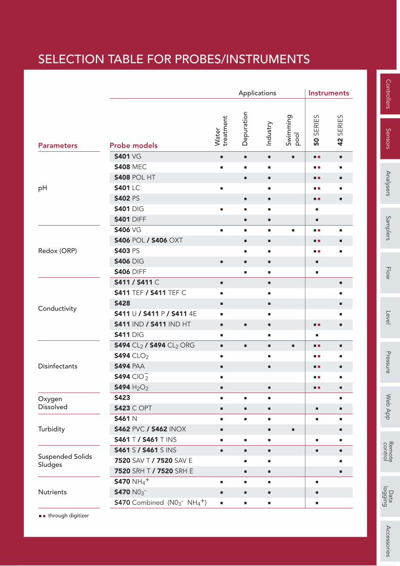
<<S411 / S411 C<<S411 TEF / S411 TEF C<<S428<<S411 U / S411 P / S411 4E
< <<S411 IND / S411 IND HT<<S411 DIG
< < <<S494 CL2 / S494 CL2 ORG<<S494 CLO2
<<S494 PAA<S494 ClO−
2
<<S494 H2O2
< <<S423< <<S423 C OPT< <<S461 N
< <<S462 PVC / S462 INOX< <<S461 T / S461 T INS< <<S461 S / S461 S INS< <7520 SAV T / 7520 SAV E< <7520 SRH T / 7520 SRH E< <<S470 NH4+
< <<S470 N03-
< <<S470 Combined (N03- NH4+)
Disinfectants
Turbidity
Suspended SolidsSludges
Nutrients
<< through digitizer
Wat
er
trea
tmen
t
Dep
urat
ion
Ind
ustr
y
Swim
min
gp
ool
<< <
<< <
<< <
<< <
<
<
<< <
<< <
<< <
<
<
<
<
<
<
<< <
<
<< <
<< <
<< <
<< <
<< <
<
< <
< <
<
< <
< <
<
<
<
<
<
50 S
ERIE
S
42 S
ERIE
S
Applications Instruments
<<S401 LC << <
Controllers
SensorsA
nalysersSam
plers
FlowLevel
PressureW
eb A
pp
Remote
controlD
atalog
ging
Accessories
8
PLUG & PLAY MULTIPARAMETRIC INSTRUMENT
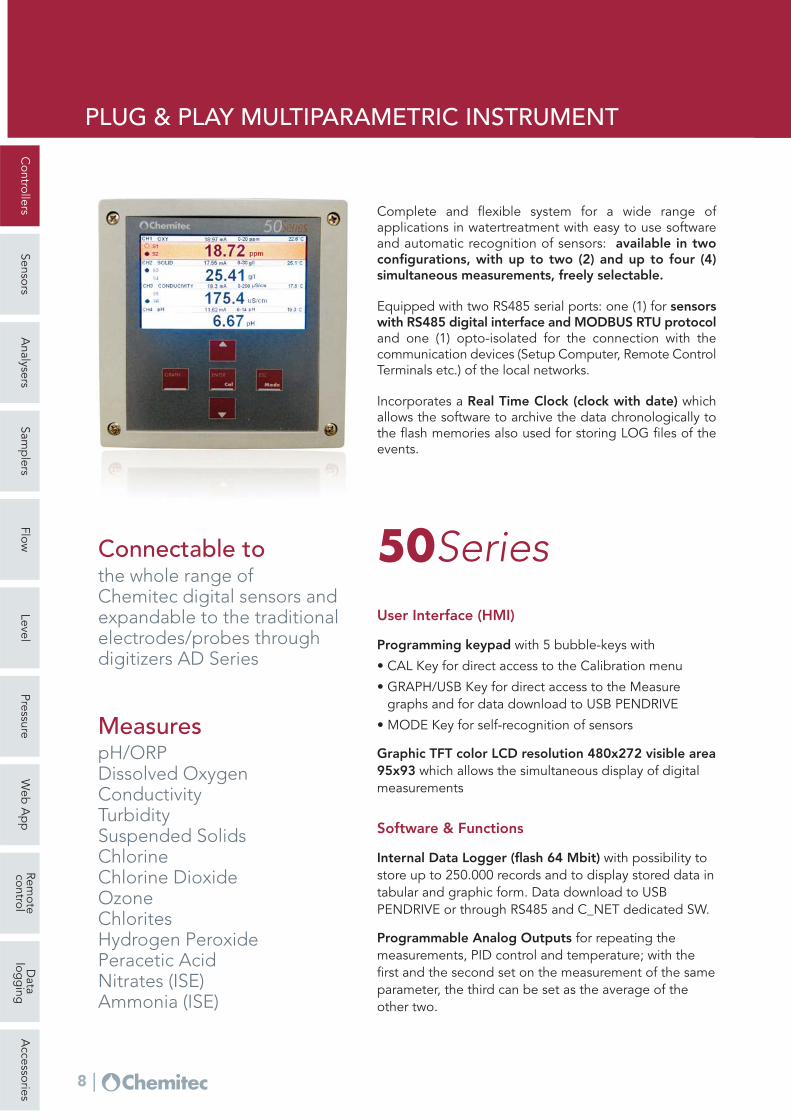
Complete and flexible system for a wide range ofapplications in watertreatment with easy to use softwareand automatic recognition of sensors: available in twoconfigurations, with up to two (2) and up to four (4)simultaneous measurements, freely selectable.
Equipped with two RS485 serial ports: one (1) for sensorswith RS485 digital interface and MODBUS RTU protocoland one (1) opto-isolated for the connection with thecommunication devices (Setup Computer, Remote ControlTerminals etc.) of the local networks.
Incorporates a Real Time Clock (clock with date) whichallows the software to archive the data chronologically tothe flash memories also used for storing LOG files of theevents.
User Interface (HMI)
Programming keypad with 5 bubble-keys with
• CAL Key for direct access to the Calibration menu
• GRAPH/USB Key for direct access to the Measuregraphs and for data download to USB PENDRIVE
• MODE Key for self-recognition of sensors
Graphic TFT color LCD resolution 480x272 visible area95x93 which allows the simultaneous display of digitalmeasurements
Software & Functions
Internal Data Logger (flash 64 Mbit) with possibility tostore up to 250.000 records and to display stored data intabular and graphic form. Data download to USBPENDRIVE or through RS485 and C_NET dedicated SW.
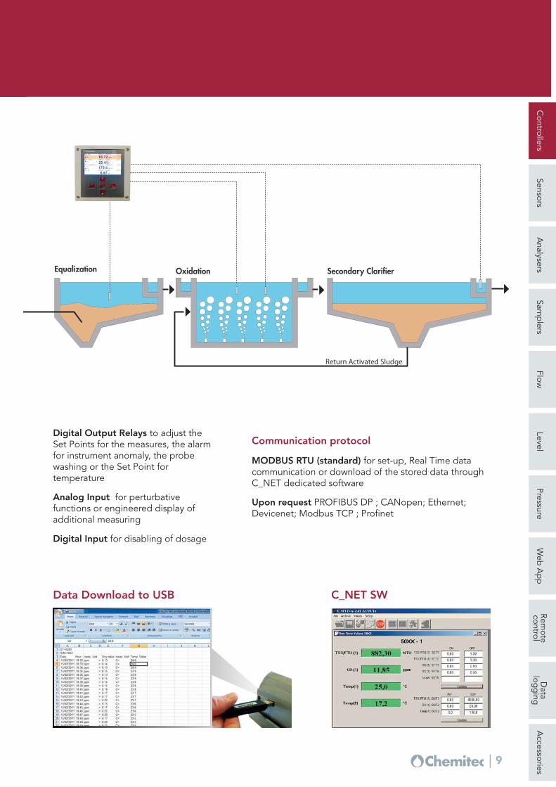
Programmable Analog Outputs for repeating themeasurements, PID control and temperature; with thefirst and the second set on the measurement of the sameparameter, the third can be set as the average of theother two.
50SeriesConnectable tothe whole range ofChemitec digital sensors and expandable to the traditionalelectrodes/probes throughdigitizers AD Series
5 bubble-keys [6] [5] single keys and [GRAPH/USB] [ESC/MODE][ENTER/CAL] keys with double functions available
Keypad
Internal Flash 64Mbit Memory up to 250,000 records with arecording interval of 15 sec up to 120 minutes
Data Logger
Circular (F.I.F.O.) or FillingRecording method
In tabular and graphic form, with indication of maximum, minimumand average values of the selected period. Zoom function.
Display of stored data
Settable functions P [Proportional] ; PI [Proportional – Integral] andPID [Proportional – Integral – Derivative]
PID Control
Four (4) programmable ; 0/4 ÷ 20 mA ; Galvanic separation ; 1KVOptoisolator ; Maximum load 500 Ohm ; Output limits userprogrammable between measuring ranges
Analog Outputs
Six (6) ; Switching Relays usable as NO ; Maximum resistive load3A at 230Vac
Digital Outputs
Working range setting (Hysteresis/direction) ; pause/working time setting 000 ÷ 999 Seconds ; PID Control ; Pulse Frequency orPWM
Set Point (4)
Alarm: Instrument failure, min/max value, set point delay,permanence time (live check) ; Delay time ; Set Point disabling (incase of alarm): Enable/Disable Wash: Programmable interval (minimum 15 minuts) and durationbetween 00:00 ÷ 24:00 hh:mm; during the washing phase, all digitaland analog outputs are frozen
Alarm/Wash (2)
NAMUR ; 2.4 mA [with range 4 ÷ 20 mA ]Alarm output
On analog or digital outputActivation
0 ÷ 500%Proportional range
Integral and/or derivative 0:00 ÷ 5:00 minTime
Controllers
SensorsA
nalysersSam
plers
FlowLevel
PressureW
eb A
pp
Remote
controlD
atalog
ging
Accessories
11
Hardware features, software features and functions 50Series
To disable dosing or activate wash cycleDigital Inputs (2)
RS485 programmable for set-up and Real Time data acquisition fromremote or download stored data (using dedicated SW)
Developed by Chemitec for industrial applications, it isequipped with an output for proportional control, controlfunctions of the probe conditions and other variousoutputs. The user has full control of the programming.
User Interface (HMI)
Programming keypad with 5 bubble-keys for calibrationand instrument configuration with:– GRAPH key to display the stored data in tabular and
graphic form.
Monochromatic display 128 x 64 pixel with graphicicons to display the status of the digital output, therecording data, the wash cycle and the alarm. Scrollingoutput values.
Software & Functions
Manual controls thanks to the intuitive programmingmenu it is very easy to start and control the dosingsystem.
Data Logger of Circular (F.I.F.O.) or Filling type on aninternal flash memory with a recording interval of 1 to 99min. (about 16000 records).
RS485 Serial Port for set-up and remote real timeacquisition or for downloading the stored data on aportable or desktop PC (using dedicated software),through MODBUS RTU communication protocol.
USB Port to download measurement data directly on aremovable PEN DRIVE memory (on request).
Analog Input for perturbative functions (interactionsbetween two parameters).
Digital Input for disabling of dosage or comand forwashing from remote.
Temperature compensation through PT100 sensor with3 or 4 wires, or PT 1000
Hardware features, software features and functions 42Series
Two (2) programmable ; 4÷20mA galvanically isolated ; Outputlimits user programmable between measuring ranges
Analog Outputs
Four (4) ; Switching Relays usable as NO ; Maximum resistive load3A at 230Vac
Digital Outputs
Two (2) for each of the two measures ; working range setting(Hysteresis/direction) ; pause/working time setting 000 ÷ 999Seconds ; PID Control ; Pulse Frequency or PWM
Set Point On – Off
One (1) programmable for: minimum/maximum value, set point delay, permanence time (live check) ; delay time 00:00 ÷ 59:99 mm:ss at minimum steps of 15 sec ; permanencetime 00:00 ÷ 99:99 hh:mm ; Set Point disabling in case of alarm:Enable/Disable
Alarm or Set Point forTemperature
programmable for measureOutput 1
programmable for measure / Temperature / PID ControlOutput 2
144 x 144 x 122.5 mm with a mounting depth of 122.5 mmDimensions (L x H x P)
IP 66Mechanical protection
1 KgWeight
PanelMounting
ABS BlackHousing material
96 x 96 x 115.5 mm with a mounting depth of 130 mmDimensions (L x H x P)
IP 54Mechanical protection
0.7 KgWeight
One (1) to program the interval (minimum 15 minuts) and theduration from 00:00 ÷ 24:00 hh:mm; during the washing phase,the digital and analog outputs and the temperature are frozen
Automatic sensorwashing or Set Point forTemperature
Controllers
SensorsA
nalysersSam
plers
FlowLevel
PressureW
eb A
pp
Remote
controlD
atalog
ging
Accessories
14
ELECTRODES FOR PH AND ORP MEASUREMENT
120 mm
Ø 12
S401VG
S406VG
S408MEC
S406OXT
S408POL Plus
S401LC
120 mm
Ø 12
120 mm
Ø 12120 m
m
Ø 12
120 mm
Ø 12
S402PS
S403PS
S406POL
General features
The electrodes listed below are all of thecombined type (Measurement+Reference),without maintenance, and are classified bytheir construction features, which makes themadaptable to multiple applications.
Models and Applications
S401VGCombined pH electrode for general use
S406VGCombined ORP electrode for general use
S408MECCombined pH electrode for high temperatureliquids and/or installations under pressure
S408POL PlusCombined pH electrode for harsh chemicalapplications
S406POLCombined ORP electrode for harsh chemicalapplications
S406OXTCombined ORP electrode for high temperatureliquids and/or installations under pressure
S401LCCombined pH electrode for waters with lowelectrical conductivity
S402PS pH electrode for applications involving liquidswith a high suspended solids content
S403PS ORP electrode for applications involving liquidswith a high suspended solids content
Digitizer for pH and ORP electrodes
The AD Series Chemitec digitizers convert thesignals of the common pH and ORP electrodesinto serial signal with standard Modbus RTUprotocol, allowing the connection to the50Series plug & play multiparametric instrument
Pg 13.5 Pg 13.5 Pg 13.5 Pg 13.5 standard Ø 12Connection to process
5 mt 5 mt 5 mt 5 mt integral 5 mt Cable
Technical specifications Electrodes for pH measurement
0 ÷ 60°C
6 bar
S406VG
±1000 mVMeasuring range
Models
Operating temperature
Maximum pressure
50 μS/cmMin. liquid conductivity
GlassBody material
GELElectrolyte
single open hole
Junction
“S7”screwCable connection
Pg 13.5Connection to process
5 mt
-10 ÷ 60°C
6 bar
S406POL
±2000 mV
2 μS/cm
Glass
Polysolve
single open hole
“S7”screw
Pg 13.5
5 mt
0 ÷ 80°C
0.2 bar
S403PS
±1000 mV
5 μS/cm
Glass
KCl - KNO3
single annularceramic
fixed
standard Ø 12
integral 5 mt Cable
Technical specifications Electrodes for ORP measurement
0 ÷ 130°C
16 bar
S406OXT
±2000 mV
50 μS/cm
Glass
GEL
3 ceramicdiaphragm
“S7”screw
Pg 13.5
5 mt
Controllers
SensorsA
nalysersSam
plers
FlowLevel
PressureW
eb A
pp
Remote
controlD
atalog
ging
Accessories
16
Models
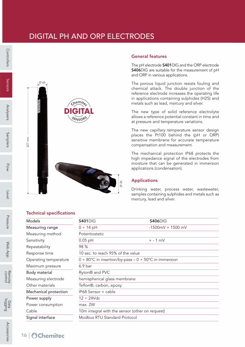
DIGITAL PH AND ORP ELECTRODES
General features
The pH electrode S401DIG and the ORP electrodeS406DIG are suitable for the measurement of pHand ORP in various applications.
The porous liquid junction resists fouling andchemical attack. The double junction of thereference electrode increases the operating lifein applications containing sulphides (H2S) andmetals such as lead, mercury and silver.
The new type of solid reference electrolyteallows a reference potential constant in time andat pressure and temperature variations.
The new capillary temperature sensor designplaces the Pt100 behind the (pH or ORP)sensitive membrane for accurate temperaturecompensation and measurement.
The mechanical protection IP68 protects thehigh impedance signal of the electrodes frommoisture that can be generated in immersionapplications (condensation).
Applications
Drinking water, process water, wastewater,samples containing sulphides and metals such asmercury, lead and silver.
0 ÷ 14 pH -1500mV + 1500 mVMeasuring range
PotentiostaticMeasuring method
0.05 pH + - 1 mVSensitivity
98 %Repeatability
10 sec. to reach 95% of the valueResponse time
0 ÷ 80°C in insertion/by-pass – 0 ÷ 50°C in immersionOperating temperature
6.9 bar Maximum pressure
Ryton® and PVCBody material
hemispherical glass membraneMeasuring electrode
IP68 Sensor + cableMechanical protection
12 ÷ 24Vdc Power supply
max. 2WPower consumption
10m integral with the sensor (other on request)Cable
Teflon®, carbon, epoxyOther materials
Modbus RTU Standard Protocol Signal interface
S401DIG S406DIG
Technical specifications
Ø 3
6
227
mm
Ø 44
DIGITALSENSORS
Chemitec
Controllers
SensorsA
nalysersSam
plers
FlowLevel
PressureW
eb A
pp
Remote
controlD
atalog
ging
Accessories
17
Models
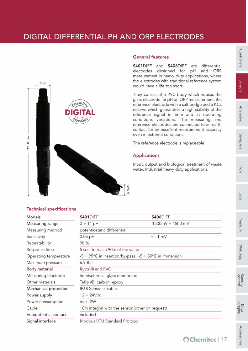
DIGITAL DIFFERENTIAL PH AND ORP ELECTRODES
General features
S401DIFF and S406DIFF are differentialelectrodes designed for pH and ORPmeasurement in heavy duty applications, wherethe electrodes with traditional reference systemwould have a life too short.
They consist of a PVC body which houses theglass electrode for pH or ORP measurement, thereference electrode with a salt bridge and a KCLreserve which guarantees a high stability of thereference signal in time and at operatingconditions variations. The measuring andreference electrodes are connected to an earthcontact for an excellent measurement accuracyeven in extreme conditions.
The reference electrode is replaceable.
Applications
Input, output and biological treatment of wastewater. Industrial heavy duty applications.
0 ÷ 14 pH -1500mV + 1500 mVMeasuring range
potentiostatic differentialMeasuring method
0.05 pH + - 1 mVSensitivity
98 %Repeatability
5 sec. to reach 90% of the valueResponse time
-5 ÷ 95°C in insertion/by-pass ; -5 ÷ 50°C in immersionOperating temperature
6.9 BarMaximum pressure
Ryton® and PVCBody material
hemispherical glass membraneMeasuring electrode
IP68 Sensor + cableMechanical protection
12 ÷ 24Vdc Power supply
max. 2WPower consumption
10m integral with the sensor (other on request)Cable
Teflon®, carbon, epoxyOther materials
includedEquipotential contact
Modbus RTU Standard Protocol Signal interface
S401DIFF S406DIFF
Technical specifications
¾ G
AS
319.
50 m
m
Ø 44
DIGITALSENSORS
Chemitec
Controllers
SensorsA
nalysersSam
plers
FlowLevel
PressureW
eb A
pp
Remote
controlD
atalog
ging
Accessories
18
1S411TEF C
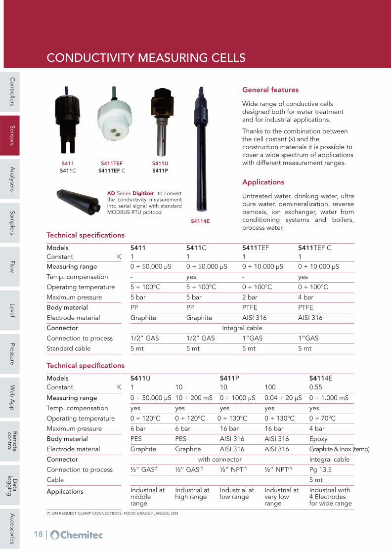
CONDUCTIVITY MEASURING CELLS
General features
Wide range of conductive cellsdesigned both for water treatmentand for industrial applications.
Thanks to the combination betweenthe cell costant (k) and theconstruction materials it is possible tocover a wide spectrum of applicationswith different measurement ranges.
Applications
Untreated water, drinking water, ultrapure water, demineralization, reverseosmosis, ion exchanger, water fromconditioning systems and boilers,process water.
0 ÷ 120°C
6 bar
S411U1
PES
Graphite
with connector
½” GAS(*)
0 ÷ 130°C
16 bar
S411P10
AISI 316
AISI 316
½” NPT(*)
0 ÷ 70°C
4 bar
S4114E
0 ÷ 120°C
6 bar
10
PES
Graphite
½” GAS(*)
0 ÷ 130°C
16 bar
100
AISI 316
AISI 316
½” NPT(*)
0.55
Epoxy
Graphite & Inox (temp)
Integral cable
Pg 13.5
5 mt
Industrial atmiddle range
Industrial athigh range
Industrial atlow range
Industrial atvery low range
Industrial with 4 Electrodes for wide range
0 ÷ 50.000 μS 10 ÷ 200 mS 0 ÷ 1000 μS 0.04 ÷ 20 μS 0 ÷ 1.000 mS
yes yes yes yes yes
5 ÷ 100°C
5 bar
S411Models
Operating temperature
Maximum pressure
1Constant K
PPBody material
GraphiteElectrode material
Integral cableConnector
1/2” GASConnection to process
5 mt
5 ÷ 100°C
5 bar
S411C1
PP
Graphite
1/2” GAS
5 mt
0 ÷ 100°C
2 bar
S411TEF1
PTFE
AISI 316
1”GAS
5 mt
0 ÷ 100°C
4 bar
PTFE
AISI 316
1”GAS
5 mt
-Temp. compensation yes - yes
Standard cable
Technical specifications
0 ÷ 50.000 μSMeasuring range
Models
Operating temperature
Maximum pressure
Constant K
Body material
Electrode material
Connector
Connection to process
Temp. compensation
Cable
Applications
(*) ON REQUEST CLAMP CONNECTIONS, FOOD GRADE FLANGES, DIN
Technical specifications
Measuring range
0 ÷ 50.000 μS 0 ÷ 10.000 μS 0 ÷ 10.000 μS
S411S411C
S411TEFS411TEF C
S411US411P
S4114E
AD Series Digitizer to convertthe conductivity measurementinto serial signal with standardMODBUS RTU protocol
Controllers
SensorsA
nalysersSam
plers
FlowLevel
PressureW
eb A
pp
Remote
controlD
atalog
ging
Accessories
19
Operating pressure
INDUCTIVE CONDUCTIVITY MEASURING CELLS
S411INDThe inductive sensor has been engineered toproduce a low cost sensor, without sacrificingperformance or quality. The result has beenobtained by moulding the sensor usingpolypropylene reinforced with fibreglass. Thesensor provides all of the benefits that the methodof inductive conductivity measurement provides.
Applications
Polluted surface waters, process monitoring,means very contaminated or aggressive, influ-ential water of treatment plants and wastewater.
Models
S411INDsensor only
S411IND Tfor immersion
S411IND Efor insertion with T-fitting
S411IND INSfor direct insertion on flat wall
Digitizer for inductive measuring cells
The AD Series Chemitec digitizers convert theconductivity measurement into serial signal withstandard Modbus RTU protocol
General features
The conductivity measuring system usinginductive sensors has many advantages overother conventional methods. The absence ofelectrodes in contact with the fluid to bemeasured makes the system recalibration andmaintenance virtually useless over long periodsof time. The S411IND sensors have a greattolerance with respect to the coatingphenomena, probably the most commonproblem encountered when measuring withconventional electrodes.
- 5 to 60°C (not freezing)
Sensore
PVC with Viton® seals
Glass-reinforced polypropylene
Mechanical construction
Material
Contact materials
Operating temperature
1000 uS … 1000 mSMeasuring range
Temperature sensor Pt1000 with 2 wiresTemp. compensation
Standard 5 metersCable
600 or 1200 mmImmersion length
Standard bracket or optional flange Mounting
0.5" BSP maleConnection
IP68Protection grade
Vacuum to 6.5 bar (100 psi)
Technical specifications S411IND
Serie AD
S411IND ES411IND
S411IND T
S411IND T INS
Controllers
SensorsA
nalysersSam
plers
FlowLevel
PressureW
eb A
pp
Remote
controlD
atalog
ging
Accessories
20
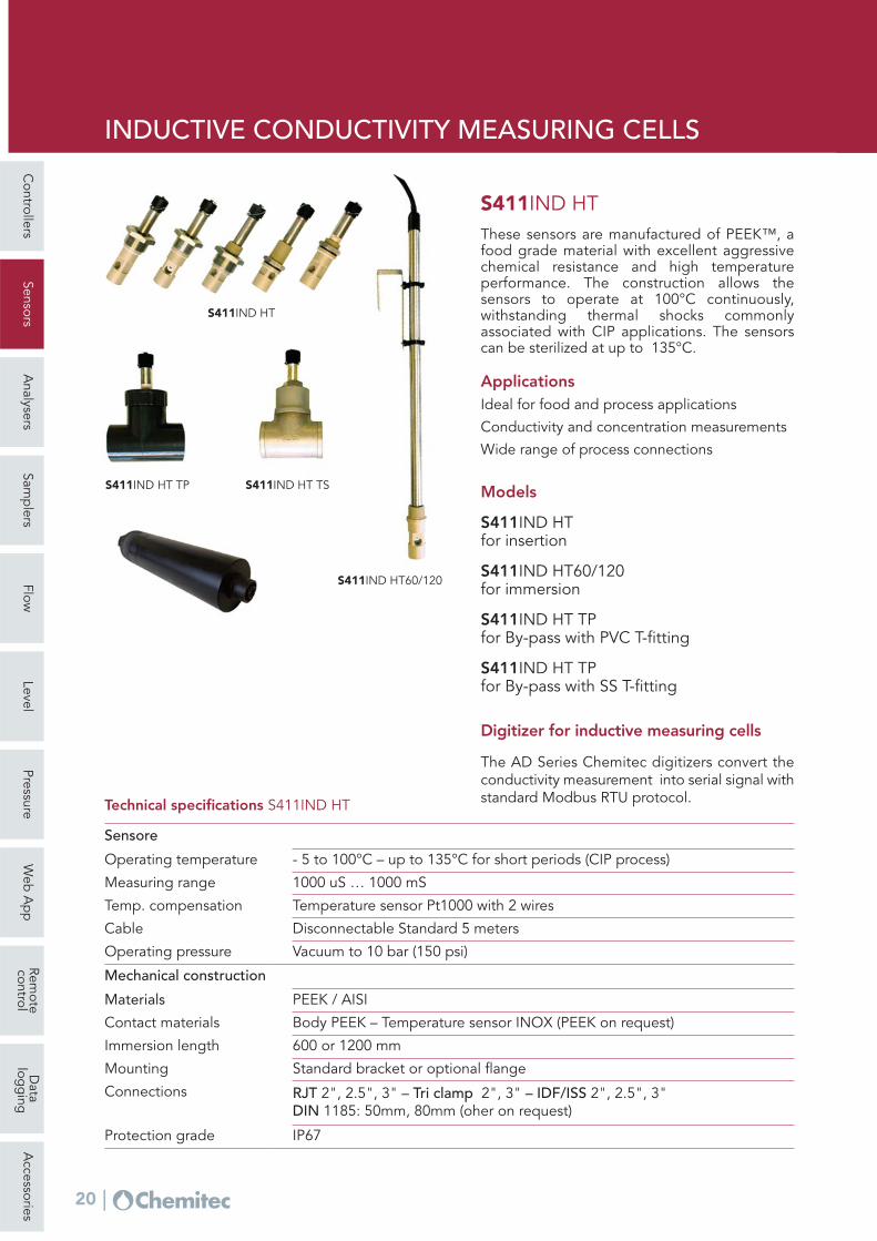
Applications Ideal for food and process applications
Conductivity and concentration measurements
Wide range of process connections
Models
S411IND HTfor insertion
S411IND HT60/120for immersion
S411IND HT TPfor By-pass with PVC T-fitting
S411IND HT TPfor By-pass with SS T-fitting
Digitizer for inductive measuring cells
The AD Series Chemitec digitizers convert theconductivity measurement into serial signal withstandard Modbus RTU protocol.
Operating pressure
- 5 to 100°C – up to 135°C for short periods (CIP process)
Sensore
PEEK / AISI
Body PEEK – Temperature sensor INOX (PEEK on request)
Mechanical construction
Materials
Contact materials
Operating temperature
1000 uS … 1000 mSMeasuring range
Temperature sensor Pt1000 with 2 wires
Disconnectable Standard 5 meters
Temp. compensation
Cable
600 or 1200 mmImmersion length
Standard bracket or optional flange Mounting
RJT 2", 2.5", 3" – Tri clamp 2", 3" – IDF/ISS 2", 2.5", 3"DIN 1185: 50mm, 80mm (oher on request)
Connections
IP67Protection grade
Vacuum to 10 bar (150 psi)
Technical specifications S411IND HT
S411IND HTThese sensors are manufactured of PEEK™, afood grade material with excellent aggressivechemical resistance and high temperatureperformance. The construction allows thesensors to operate at 100°C continuously,withstanding thermal shocks commonlyassociated with CIP applications. The sensorscan be sterilized at up to 135°C.
S411IND HT
S411IND HT60/120
S411IND HT TSS411IND HT TP
INDUCTIVE CONDUCTIVITY MEASURING CELLS
Controllers
SensorsA
nalysersSam
plers
FlowLevel
PressureW
eb A
pp
Remote
controlD
atalog
ging
Accessories
21
Power supply
General features
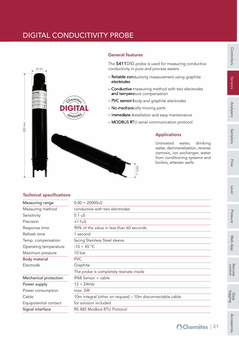
The S411DIG probe is used for measuring conductiveconductivity in pure and process waters.
– Reliable conductivity measurement using graphiteelectrodes
– Conductive measuring method with two electrodesand temperature compensation
– PVC sensor body and graphite electrodes
– No mechanically moving parts
– Immediate installation and easy manteinance
– MODBUS RTU serial communication protocol
0.00 ÷ 20000uSMeasuring range
conductive with two electrodesMeasuring method
0.1 uSSensitivity
+/-1uSPrecision
90% of the value in less than 60 secondsResponse time
1 secondRefresh time
facing Stainless Steel sleeveTemp. compensation
-10 ÷ 45 °COperating temperature
10 barMaximum pressure
PVCBody materialGraphiteElectrode
IP68 Sensor + cableMechanical protection
12 ÷ 24Vdc
max. 2WPower consumption
10m integral (other on request) – 10m disconnectable cableCable
The probe is completely resinate inside
for solution includedEquipotential contact
RS 485 Modbus RTU ProtocolSignal interface
Technical specifications
1” G
AS
220
mm
Ø 33
Applications
Untreated water, drinkingwater, demineralization, reverseosmosis, ion exchanger, waterfrom conditioning systems andboilers, artesian wells
DIGITALSENSORS
Chemitec
DIGITAL CONDUCITIVITY PROBE
Controllers
SensorsA
nalysersSam
plers
FlowLevel
PressureW
eb A
pp
Remote
controlD
atalog
ging
Accessories
22
Response
Body material
Operating conditions
Stability
Digitizer for amperometricsensors
The AD Series Chemitec digitizerconverts the S494 sensor signals intoserial signal with standard ModbusRTU protocol allowing the connectionto the 50Series plug & play digitalinstrument.
175
mm
Ø 25 mm General features
The S494 are amperometricprobes with two (2) or three (3)electrodes covered withmembrane with integratedtemperature sensor for signalcompensation.
Applications
Swimming pool, drinking water,waste water, process water.
Technical specifications
±2 % of the indicated valueMeasuring error
±2 %Repeatability
±1 % of the analytical determination after 4 weeks from the calibration
The oxygen content in liquids is measured with a system called Clark's cells.These cells generate an electrical current proportional to the oxygen partialpressure which can be evaluated with a suitable measurement converter.
In order to prevent interference effects on measuring, the Clark's cells arecovered with a gas-permeable membrane. The membranes typically usedare made from PTFE but, as this material is mechanically fragile, frequentchanging is often necessary, along with the related “demanding” operations(interruption of measurement, electrolyte replacement, regeneration of theelectrodes).
The S423 solves this problem by using an OPTIFLOW™ membrane. Thismembrane is very mechanically stable, is manufactured as a laminatearound a steel mesh and is very resistant to chemically aggressiveenvironments as well as high pressures.
Thanks to the special construction of the measuring electrodes, this systemalso makes the sensor totally “maintenance free”.
Applications
Surface waters, drinking water, biological treatment of waste water.
40 ppb ÷ 40 ppmMeasuring range
measure of the electric current influenced by the oxygen partial pressure Measuring method
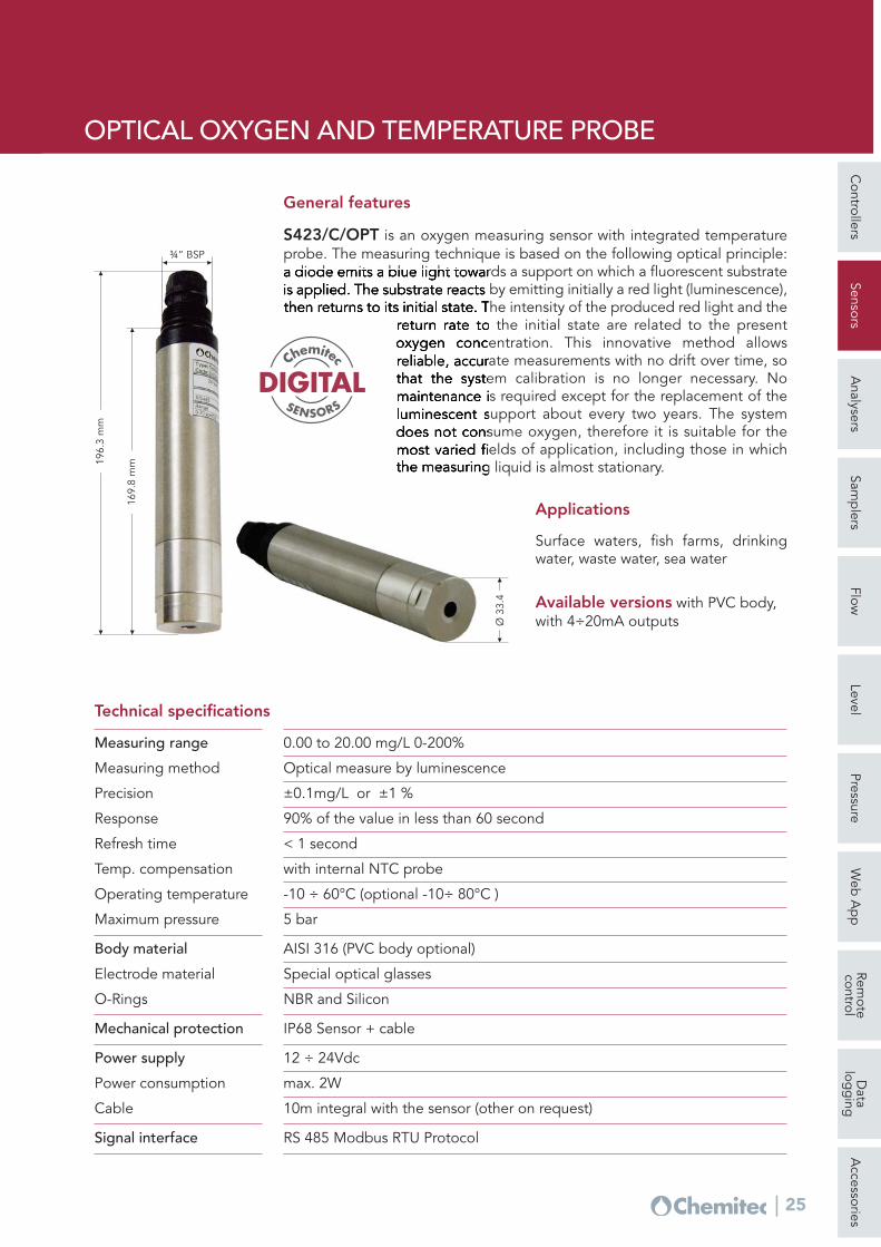
S423/C/OPT is an oxygen measuring sensor with integrated temperatureprobe. The measuring technique is based on the following optical principle:a diode emits a blue light towards a support on which a fluorescent substrateis applied. The substrate reacts by emitting initially a red light (luminescence),then returns to its initial state. The intensity of the produced red light and the
return rate to the initial state are related to the presentoxygen concentration. This innovative method allowsreliable, accurate measurements with no drift over time, sothat the system calibration is no longer necessary. Nomaintenance is required except for the replacement of theluminescent support about every two years. The systemdoes not consume oxygen, therefore it is suitable for themost varied fields of application, including those in whichthe measuring liquid is almost stationary.
Applications
Surface waters, fish farms, drinkingwater, waste water, sea water
Available versions with PVC body,with 4÷20mA outputs
0.00 to 20.00 mg/L 0-200%Measuring range
Optical measure by luminescenceMeasuring method
±0.1mg/L or ±1 %Precision
90% of the value in less than 60 secondResponse
< 1 secondRefresh time
with internal NTC probeTemp. compensation
-10 ÷ 60°C (optional -10÷ 80°C )Operating temperature
5 barMaximum pressure
AISI 316 (PVC body optional)Body material
Special optical glassesElectrode material
NBR and SiliconO-Rings
Technical specifications
IP68 Sensor + cableMechanical protection
12 ÷ 24Vdc Power supply
max. 2WPower consumption
10m integral with the sensor (other on request)Cable
RS 485 Modbus RTU ProtocolSignal interface
196.
3 m
m
169.
8 m
m
¾” BSP
Ø 3
3.4
DIGITALSENSORS
Chemitec
Controllers
SensorsA
nalysersSam
plers
FlowLevel
PressureW
eb A
pp
Remote
controlD
atalog
ging
Accessories
26
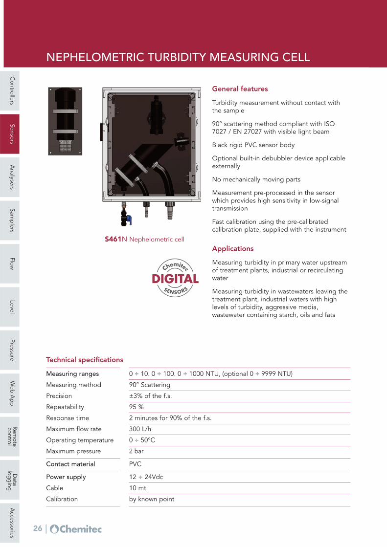
General features
Turbidity measurement without contact withthe sample
90° scattering method compliant with ISO7027 / EN 27027 with visible light beam
Measurement pre-processed in the sensorwhich provides high sensitivity in low-signaltransmission
Fast calibration using the pre-calibratedcalibration plate, supplied with the instrument
Applications
Measuring turbidity in primary water upstreamof treatment plants, industrial or recirculatingwater
Measuring turbidity in wastewaters leaving thetreatment plant, industrial waters with highlevels of turbidity, aggressive media,wastewater containing starch, oils and fats
The measuring principle is the deviation of lightproduced by the particles suspended in theliquid.
Thanks to the dual sensor system, turbidity canbe measured at low and very lowconcentrations with high levels of precisionand repeatability.
The absence of contact with the measuringliquid and the optical LED technology makethe system stable over time and minimize theneed for recalibrations.
The cell can be installed directly in-line. Themaximum allowable pressure is 6 bar, or on By-pass piping. The flow rate does not affect themeasurement.
Applications
Water treatment plants, on leaving thefiltration or decantation sections
Waste water refining plants for agricultural orindustrial reuse
Food industry, in particular in the production ofbeverages, wine, beer etc.
Swimming pools
0 ÷ 100 FTU 0 ÷ 100 FTUMeasuring range
0 ÷ 45°C 0 ÷ 90°COperating temperature
6 bar 6 barMaximum pressure
Black PVC AISI 316Body material
threaded 2 ½ “ F threaded 2 ½ “ MConnections
- Black PTFE Inner lining
Trasparent PVC Tempered glassInspection windows
positioned at 180° mounted onPVC flanges with connector forelectrical connections
positioned at 180° mounted onstainless steel 316 flanges withintegral 5 m outgoing cable
Projector and sensors
S462PVC S462INOXModels
Technical specifications
S462PVCturbidimetric cell with PVC body
LOW TURBIDITY MEASURING CELL
Controllers
SensorsA
nalysersSam
plers
FlowLevel
PressureW
eb A
pp
Remote
controlD
atalog
ging
Accessories
28
0 ÷ 4, 0 ÷ 40. 0 ÷ 400. 0 ÷ 1000 NTU (0 ÷ 4000 on request) Low turbidity version 0 ÷ 1 NTU on request
General features
Turbidity refers to the scatteredcomponent of a light beam which isdiverted away from its natural coursee by optically denser particles in themedium (e.g. solid matter particles).
The measurement isperformed by using a 90°scattered light methodcompliant with ISO 7027 /EN 27027.
The measuring method isbased on the Tyndall effect.The turbidity of the mediumis determined by theamount of scattered light.
Applications
Untreated water and wellwater, surface water,drinking water, processwater, industrial andmunicipal wastewaterseawater
Available versions withPVC body, with 4÷20mAoutputs
Measuring ranges
90° ScatteringMeasuring method
± 2% of the f.s.Precision
98 %Repeatability
5 sec. to reach the 90% of the valueResponse time
0 ÷ 60°COperating temperature
4 barMaximum pressure
Black PVC and AISI 316Body material
Viton®O-ring
Special glassOptics
IP68 Sensor + cableMechanical protection
12 ÷ 24Vdc Power supply
max. 3WPower consumption
10 mt integral with the sensorCable
Modbus RTU Standard Protocol RS485 (4 ÷ 20mA optional)Signal interface
S461T – for immersion and bypass(in combination with S305/S461T)
S461T INS – for insertion(in combination with S305/INS)
Models
Technical specifications
207
mm
20 m
m
1” GAS
Ø 4
2
DIGITALSENSORS
Chemitec
TURBIDITY PROBE
Controllers
SensorsA
nalysersSam
plers
FlowLevel
PressureW
eb A
pp
Remote
controlD
atalog
ging
Accessories
29
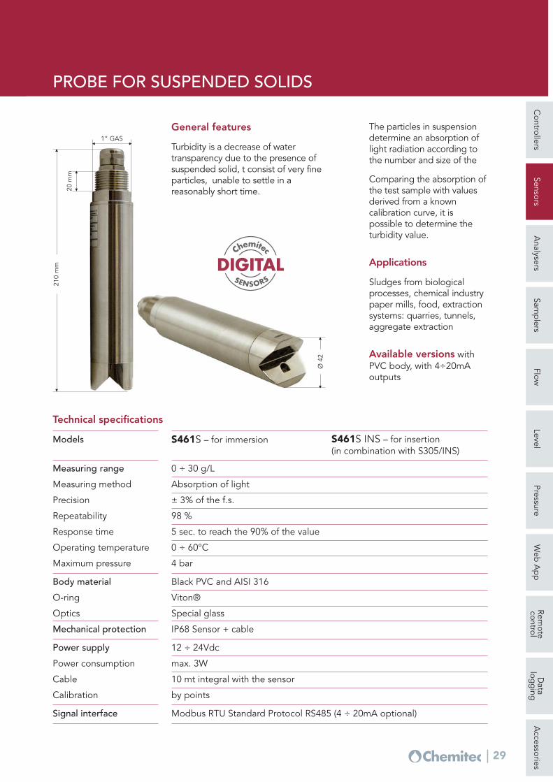
0 ÷ 30 g/LMeasuring range
Absorption of lightMeasuring method
± 3% of the f.s.Precision
98 %Repeatability
5 sec. to reach the 90% of the valueResponse time
0 ÷ 60°COperating temperature
4 barMaximum pressure
Black PVC and AISI 316Body material
Viton®O-ring
Special glassOptics
IP68 Sensor + cableMechanical protection
12 ÷ 24Vdc Power supply
max. 3WPower consumption
10 mt integral with the sensorCable
by pointsCalibration
Modbus RTU Standard Protocol RS485 (4 ÷ 20mA optional)Signal interface
S461S – for immersion S461S INS – for insertion(in combination with S305/INS)
Models
Technical specifications
210
mm
20 m
m
1” GAS
Ø 4
2
General features
Turbidity is a decrease of watertransparency due to the presence ofsuspended solid, t consist of very fineparticles, unable to settle in areasonably short time.
The particles in suspensiondetermine an absorption oflight radiation according tothe number and size of the
Comparing the absorption ofthe test sample with valuesderived from a knowncalibration curve, it ispossible to determine theturbidity value.
Applications
Sludges from biologicalprocesses, chemical industrypaper mills, food, extractionsystems: quarries, tunnels,aggregate extraction
Available versions withPVC body, with 4÷20mAoutputs
DIGITALSENSORS
Chemitec
PROBE FOR SUSPENDED SOLIDS
Controllers
SensorsA
nalysersSam
plers
FlowLevel
PressureW
eb A
pp
Remote
controlD
atalog
ging
Accessories
30
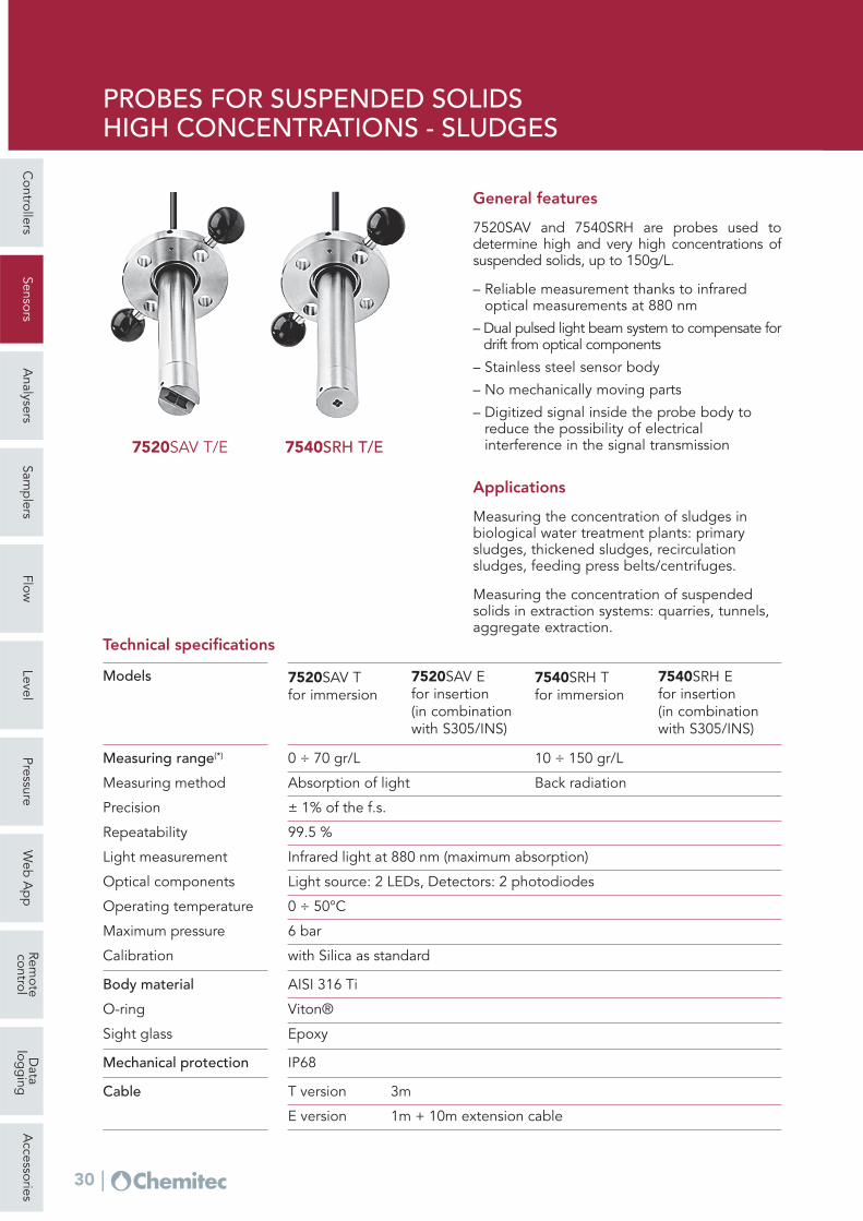
7520SAV T/E
General features
7520SAV and 7540SRH are probes used todetermine high and very high concentrations ofsuspended solids, up to 150g/L.
– Reliable measurement thanks to infraredoptical measurements at 880 nm
– Dual pulsed light beam system to compensate fordrift from optical components
– Stainless steel sensor body
– No mechanically moving parts
– Digitized signal inside the probe body toreduce the possibility of electricalinterference in the signal transmission
Applications
Measuring the concentration of sludges inbiological water treatment plants: primarysludges, thickened sludges, recirculationsludges, feeding press belts/centrifuges.
Measuring the concentration of suspendedsolids in extraction systems: quarries, tunnels,aggregate extraction.
7540SRH T/E
0 ÷ 70 gr/L 10 ÷ 150 gr/LMeasuring range(*)
Absorption of light Back radiationMeasuring method
± 1% of the f.s.Precision
99.5 %Repeatability
Infrared light at 880 nm (maximum absorption) Light measurement
PROBES FOR SUSPENDED SOLIDSHIGH CONCENTRATIONS - SLUDGES
Controllers
SensorsA
nalysersSam
plers
FlowLevel
PressureW
eb A
pp
Remote
controlD
atalog
ging
Accessories
31
Body material STAINLESS STEEL AISI316
General features
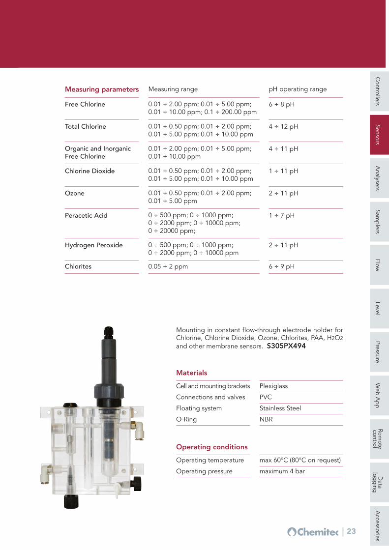
The flow-through S305/461T probe holder is used toinsert the S461 sensor for the optical measurement ofturbidity in the bypass plant.
– Reliable concentration measurement thanks to the useof an optical measurement process
– Scattering method with pulsing infrared light beams
– System with degasser to avoid the formation of airbubbles within the measuring chamber
– Gray rigid PVC probe holder body
– No mechanically moving parts
– Measurement pre-processed in the sensor whichprovides high sensitivity in low-signal transmission
– Washing system
Applications
Turbidity measurement in drinking water and in waterwith low turbidity ranges
General features
The probe holder S305/INS for insertion into the pipeis used for Turbidity/Suspended Solids sensors.
Operating temperatureMaximum pressure
Body material
0 ÷ 50 °C3 bar
Gray PVC Plate PP
Technical specifications
Ball valve DN 40 for extraction of theprobe without interruptionof the process
Complete with fixing brackets of the safetysensor
Connection welded for mounting onpipe
Technical specifications
700
mm
66
.5 m
m
420 mm
FLOW-THROUGH AND INSERTION PROBE HOLDER
Controllers
SensorsA
nalysersSam
plers
FlowLevel
PressureW
eb A
pp
Remote
controlD
atalog
ging
Accessories
32
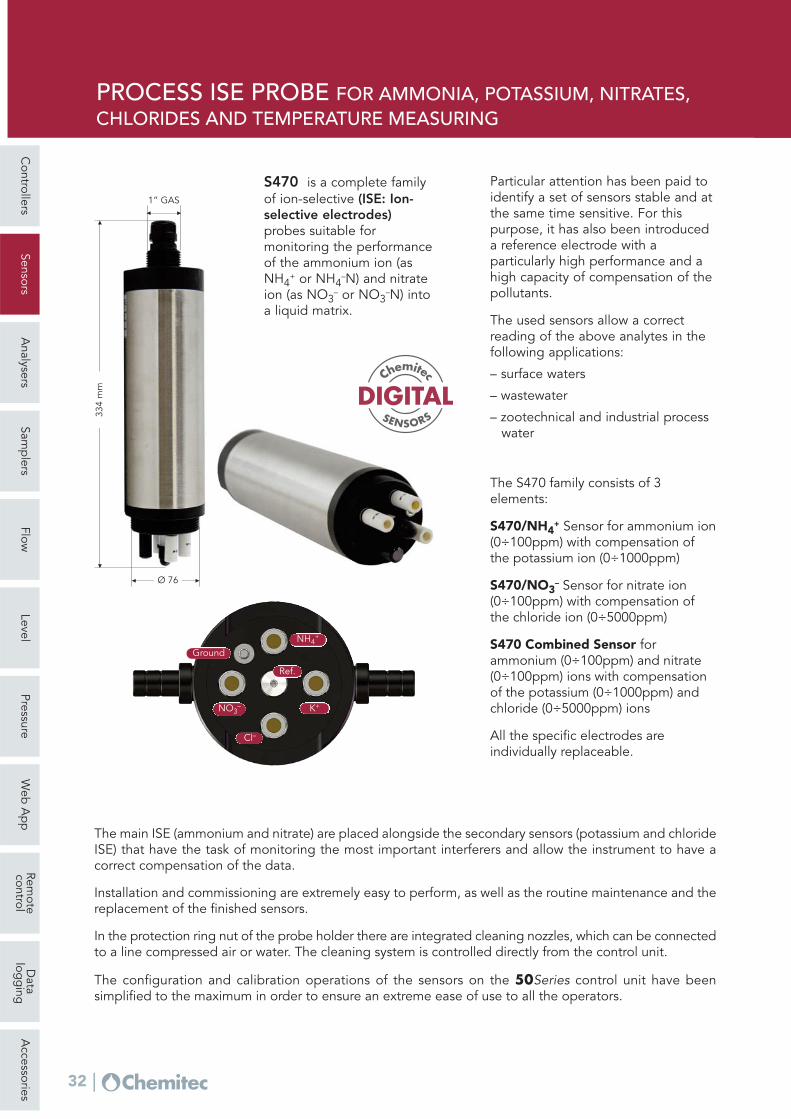
Particular attention has been paid toidentify a set of sensors stable and atthe same time sensitive. For thispurpose, it has also been introduceda reference electrode with aparticularly high performance and ahigh capacity of compensation of thepollutants.
The used sensors allow a correctreading of the above analytes in thefollowing applications:
– surface waters
– wastewater
– zootechnical and industrial process water
The S470 family consists of 3elements:
S470/NH4+ Sensor for ammonium ion
(0÷100ppm) with compensation ofthe potassium ion (0÷1000ppm)
S470/NO3– Sensor for nitrate ion
(0÷100ppm) with compensation ofthe chloride ion (0÷5000ppm)
S470 Combined Sensor forammonium (0÷100ppm) and nitrate(0÷100ppm) ions with compensationof the potassium (0÷1000ppm) andchloride (0÷5000ppm) ions
All the specific electrodes areindividually replaceable.
The main ISE (ammonium and nitrate) are placed alongside the secondary sensors (potassium and chlorideISE) that have the task of monitoring the most important interferers and allow the instrument to have acorrect compensation of the data.
Installation and commissioning are extremely easy to perform, as well as the routine maintenance and thereplacement of the finished sensors.
In the protection ring nut of the probe holder there are integrated cleaning nozzles, which can be connectedto a line compressed air or water. The cleaning system is controlled directly from the control unit.
The configuration and calibration operations of the sensors on the 50Series control unit have beensimplified to the maximum in order to ensure an extreme ease of use to all the operators.
GroundNH4
+
NO3–
Ref.
K+
Cl–
334
mm
1” GAS
Ø 76
S470 is a complete familyof ion-selective (ISE: Ion-selective electrodes)probes suitable formonitoring the performanceof the ammonium ion (asNH4
+ or NH4–N) and nitrate
ion (as NO3– or NO3
–N) intoa liquid matrix.
DIGITALSENSORS
Chemitec
PROCESS ISE PROBE FOR AMMONIA, POTASSIUM, NITRATES,CHLORIDES AND TEMPERATURE MEASURING
Controllers
SensorsA
nalysersSam
plers
FlowLevel
PressureW
eb A
pp
Remote
controlD
atalog
ging
Accessories
33
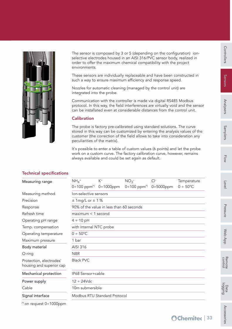
The sensor is composed by 3 or 5 (depending on the configuration) ion-selective electrodes housed in an AISI 316/PVC sensor body, realized inorder to offer the maximum chemical compatibility with the projectenvironments.
These sensors are individually replaceable and have been constructed insuch a way to ensure maximum efficiency and response speed.
Nozzles for automatic cleaning (managed by the control unit) areintegrated into the probe.
Communication with the controller is made via digital RS485 Modbusprotocol. In this way, the field interferences are virtually void and the sensorcan be installated even at considerable distances from the control unit.
Calibration
The probe is factory pre-calibrated using standard solutions. The curvestored in this way can be customized by entering the analysis values of thecustomer (the correction of the field allows to take into consideration anypeculiarities of the matrix).
It's possible to enter a table of custom values (6 points) and let the probework on a custom curve. The factory calibration curve, however, remainsalways available and could be set again as default.
NH4+
0÷100 ppm(*)
K+
0÷1000ppmNO3
–
0÷100 ppm(*)
Cl-
0÷5000ppmTemperature0 ÷ 50°C
Measuring range
Ion-selective sensorsMeasuring method
± 1mg/L or ± 1 %Precision
90% of the value in less than 60 secondsResponse
maximum < 1 secondRefresh time
4 ÷ 10 pHOperating pH range
0 ÷ 50°COperating temperature
1 barMaximum pressure
AISI 316Body material
NBRO-ring
Black PVC Protection, electrodes'housing and superior cap
IP68 Sensor+cableMechanical protection
Technical specifications
with internal NTC probeTemp. compensation
12 ÷ 24Vdc Power supply
10m submersibleCable
Modbus RTU Standard ProtocolSignal interface
(*) on request 0÷1000ppm
Proper management of thenitrogen and the carbon cycle iscrucial to get the respect of thelimits of the law and, at thesame time, avoid wastingresources.
The market offers manydedicated solutions, with varyingdegrees of effectiveness, butmostly targeted -for the kind ofthe investment- to plants ofimportant dimensions (>10Kae).
Chemitec worked hard to find aperforming solution even whereit's not possible to apply theusual systems of supervision andcontrol.
Plug & play multiparametric instrument
Process ISE probe
Oxysmart is a control algorithm. It is based on theassumption, verified in a first approximation, that it ispossible, in a civil treatment plant, to monitor theincoming load by controlling the concentration ofammonia nitrogen.
Loaded on a 50 Series Controller, this algorithmtransforms the control unit into a system capable tomanage compressors, inverters and mixers, to optimizethe process and adapt it to load variations.
The 50Series Oxysmart is installed at the poolside andis operative from the start. The logic is adaptable to anyplant, regardless of the electromechanical equipment,but, however, optimizing the operation.
The oxygen setpoint is varied in a continuous manneraccording to the load detected by the ammonia-ionselective probe Chemitec S470/NH4 and its abatement.
The Chemitec S423/C/OPT oxygen probe isresponsible for monitoring the achievement of theimposed target.
Oxysmart Chemitec
Controllers
SensorsA
nalysersSam
plers
FlowLevel
PressureW
eb A
pp
Remote
controlD
atalog
ging
Accessories
34
PLUG & PLAY AUTOMATIONFOR BIOLOGICAL SEWAGE TREATMENT PLANTS
Controllers
SensorsA
nalysersSam
plers
FlowLevel
PressureW
eb A
pp
Remote
controlD
atalog
ging
Accessories
35
There are three logics, adaptable to any plant:
Oxysmart provides a series of safeties toprotect the compressors and inverters, aswell as to compensate the failure of theprobes. Alarm functions are provided incase of malfunction of some component:the system automatically positions theadjustments of the safety values.
The benefits of Oxysmart system are::
Economical: reduced intervention costs
Technical: immediate start, ease ofinstallation and management
Managerial: energy consumptionoptimization, stability of the effluent’sparameters
Operating example (Smart N/DN logic, simulationof inverter failure, 4000ae)
Smart DO In conditions of low load, the DO thresholdis maintained at low levels, and then itgrows when the load increases.
Smart N/DN At the end of an oxidation cycle, thesystem activates the mixer, turns off thecompressors and waits for a peak ofammonia nitrogen; when the peak isreached, the system reactivates oxidation
Smart ON/OFF In conditions of low load, the system goesin pause/work mode, ready to modulatethe oxygen when the load increases.
Controllers
SensorsA
nalysersSam
plers
FlowLevel
PressureW
eb A
pp
Remote
controlD
atalog
ging
Accessories
36
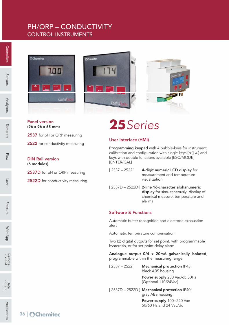
User Interface (HMI)
Programming keypad with 4 bubble-keys for instrumentcalibration and configuration with single keys [6][5] andkeys with double functions available [ESC/MODE][ENTER/CAL]
0 ÷ 60 °C 0 ÷ 100 °C 0 ÷ 60 °C 0 ÷ 100 °CTemperature
± 1°C ± 1°CResolution
AutomaticTemp. compensation
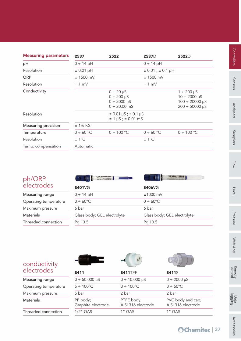
conductivityelectrodes
Materials PP body;Graphite electrode
PTFE body;AISI 316 electrode
PVC body and cap;AISI 316 electrode
S411 S411TEF S411S
Operating temperature
Maximum pressure
Measuring range
5 ÷ 100°C
0 ÷ 50.000 μS 0 ÷ 10.000 μS 0 ÷ 2000 μS
0 ÷ 100°C 0 ÷ 50°C
5 bar 2 bar 2 bar
Pg 13.5Threaded connection
ph/ORPelectrodes
Materials Glass body; GEL electrolyte
S401VG
Operating temperature
Maximum pressure
Measuring range
0 ÷ 60°C
0 ÷ 14 pH
6 bar
Pg 13.5
Glass body; GEL electrolyte
S406VG
0 ÷ 60°C
±1000 mV
6 bar
Controllers
SensorsA
nalysersSam
plers
FlowLevel
PressureW
eb A
pp
Remote
controlD
atalog
ging
Accessories
38
PORTABLE METER TO MEASURE
THE BIOMASS RESPIRATORY ACTIVITY
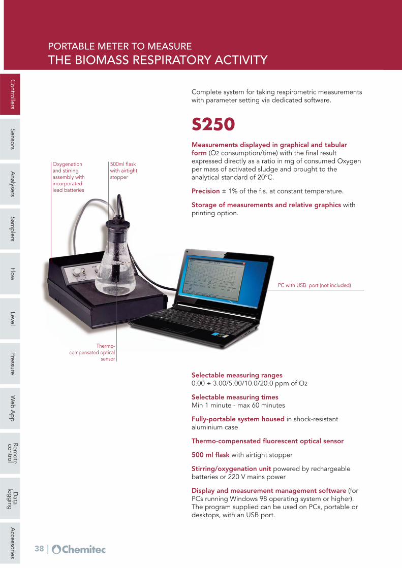
Oxygenation and stirringassembly withincorporatedlead batteries
500ml flaskwith airtightstopper
Complete system for taking respirometric measurementswith parameter setting via dedicated software.
S250Measurements displayed in graphical and tabularform (O2 consumption/time) with the final resultexpressed directly as a ratio in mg of consumed Oxygenper mass of activated sludge and brought to theanalytical standard of 20°C.
Precision ± 1% of the f.s. at constant temperature.
Storage of measurements and relative graphics withprinting option.
Thermo-compensated optical
sensor
PC with USB port (not included)
Selectable measuring ranges0.00 ÷ 3.00/5.00/10.0/20.0 ppm of O2
Selectable measuring timesMin 1 minute - max 60 minutes
Fully-portable system housed in shock-resistantaluminium case
Thermo-compensated fluorescent optical sensor
500 ml flask with airtight stopper
Stirring/oxygenation unit powered by rechargeablebatteries or 220 V mains power
Display and measurement management software (forPCs running Windows 98 operating system or higher).The program supplied can be used on PCs, portable ordesktops, with an USB port.
Controllers
SensorsA
nalysersSam
plers
FlowLevel
PressureW
eb A
pp
Remote
controlD
atalog
ging
Accessories
39
O.U.R. TEST (OXYGEN UPTAKE RATE)
The measurement of OUR
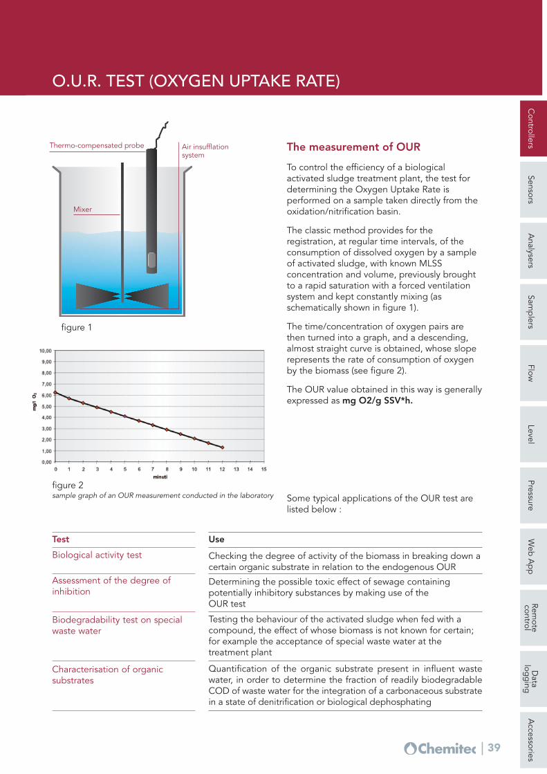
To control the efficiency of a biologicalactivated sludge treatment plant, the test fordetermining the Oxygen Uptake Rate isperformed on a sample taken directly from theoxidation/nitrification basin.
The classic method provides for theregistration, at regular time intervals, of theconsumption of dissolved oxygen by a sampleof activated sludge, with known MLSSconcentration and volume, previously broughtto a rapid saturation with a forced ventilationsystem and kept constantly mixing (asschematically shown in figure 1).
The time/concentration of oxygen pairs arethen turned into a graph, and a descending,almost straight curve is obtained, whose sloperepresents the rate of consumption of oxygenby the biomass (see figure 2).
The OUR value obtained in this way is generallyexpressed as mg O2/g SSV*h.
Mixer
Air insufflationsystem
Thermo-compensated probe
figure 1
figure 2 sample graph of an OUR measurement conducted in the laboratory
UseTest
Checking the degree of activity of the biomass in breaking down acertain organic substrate in relation to the endogenous OUR
Biological activity test
Determining the possible toxic effect of sewage containingpotentially inhibitory substances by making use of the OUR test
Assessment of the degree ofinhibition
Testing the behaviour of the activated sludge when fed with acompound, the effect of whose biomass is not known for certain;for example the acceptance of special waste water at thetreatment plant
Biodegradability test on specialwaste water
Quantification of the organic substrate present in influent wastewater, in order to determine the fraction of readily biodegradableCOD of waste water for the integration of a carbonaceous substratein a state of denitrification or biological dephosphating
Characterisation of organicsubstrates
Some typical applications of the OUR test arelisted below :